Submitted:
22 January 2024
Posted:
23 January 2024
Read the latest preprint version here
Abstract
The production of high-quality castings without foundry defects at minimal production costs is a constant priority for foundries. Innovation and optimization of production processes are key to achieving this goal. Computer simulation of foundry processes offers a modern alternative to expensive and time-consuming experiments in real foundries and provides a reliable representation and analysis of casting and solidification processes. A detailed analysis of the casting and solidification simulation results allows the prediction of various risks that can cause defects in cast castings, thereby reducing their quality and, last but not least, the cost of their production. The paper deals with the analysis of a computer simulation of the casting of a brake disc in the Slovak foundry. This brake disc has had shrinkages and micro shrinkages that reduce the internal quality of the casting. These defects occurred in the ribs in the upper part of the casting under the feeders. A computer simulation of the casting and solidification of this casting was made according to real conditions. It turned out that the designed ingate system with a system of feeders was not sufficient to eliminate emerging defects. A new layout of the feeders was proposed, which ultimately eliminated the occurrence of defects based on the results of computer simulation. The input parameters were set to be as close as possible to the actual needs of the foundry. 3D models of the assemblies were designed in SolidWorks CAD software, and filling and solidification simulations were performed using the NovaFlow & Solid CV 4.6r42 simulation program.
Keywords:
computer simulation
; casting
; foundry defects
; shrinkage
; gating system
; feeder
1. Introduction
Numerical modeling of the casting process is an important tool in foundry, which is based on the use of empirical and semi-empirical physical and numerical models. These models allow the simulation and analysis of complex processes that occur during the casting process. The use of simulation software with an integrated numerical model makes it possible to obtain sophisticated solutions and data for these processes.
Solidification simulation is one application of numerical modeling that helps identify hot spots in a mold. Flow simulation is another important application that provides visualization of melt velocity during mold filling as well as filling and solidification time information. This information helps us predict and prevent melt flow disturbances and thereby predict the occurrence of defects [1,2].
Melt flow in closed systems can be laminar or turbulent. Laminar flow is maintained up to a certain critical velocity, after which the melt becomes turbulent. In turbulent flow, some of the melt’s energy is consumed to form vortices, resulting in reduced overall flow velocity and unsteady fluid flow. In swirling regions, there is an increased flow of liquid metal and a decrease in pressure, which can cause gas particles to be entrained into the melt. These particles cause wear and erosion of the molding compound, being absorbed by the melt much like gaseous particles. These inclusions have a significant impact on the quality of cast parts. The danger of particle entrainment increases as the flow velocity increases to a value of approximately 1.2 m.s-1 at which entrainment damage to the mold is likely. The flow velocity in the notches should be in the range of 0.5 to 1.0 m.s-1 [3,4,5,6].
Most of the defects in the casting and solidification process are caused by incorrect design and placement of the gating system and feeders on the casting. A correctly designed gating system and the placement of castings will ensure optimal filling of the mold cavity, directed solidification of the casting, and the formation of shrinkage in the feeder [7,8]. The formation of shrinkage in the casting is accompanied by negatively directed solidification when the melt is closed in the solidifying part of the casting, i.e. the feeder solidifies earlier than the casting [9].
In addition to the factors mentioned above, which affect the quality of the produced casting, the shrinkage of ductile iron in the solidification process is also an important phenomenon. The occurrence of withdrawals and their causes are addressed by several authors such as Chen et al. [10] and Yeung et al. [11]. Shrinkages occur in the interval liquidus - solidus. Their occurrence can be prevented by replacing the reduced volume from another source - infusion. The problem of shrinkages and feeders is described in detail in [12,13,14]. Using this process, the size of the feeders is chosen based on the volume capacity of the casting and the cast alloy. Subsequently, the shape and dimensions of the feeder are decisive for the choice of the appropriate type of feeder and their correct placement on the casting so that the metal is added to the entire volume of the casting during volumetric shrinkage. The gating system and its opening into the casting also play an important role in this process [15]. The solidification of ductile iron castings and their construction was dealt with by Bjerre et al. [16].
Volume changes in the casting during solidification (formation of shrinkage) are physical phenomena that cannot be prevented. Through technological intervention, we can ensure the formation of shrinkage in the casting and the casting solidifies in a healthy way. The formation and elimination of shrinkage and micro shrinkage in ductile cast iron was dealt with by Siclari et al. [17], and Davis [18], and its further description is given in [19].
For a casting of a given type, i.e. a casting with different wall thicknesses, positively directed solidification and the correct distribution of feeders on the casting are very important. Several authors dealt with the issues of ductile iron castings with different wall thicknesses and the possibilities of their feedering [20,21].
2. Materials and Methods
The casting of the brake disc, for which the gating system was verified, is produced in the Slovak foundry. The casting is made of ductile iron EN-GJS-400-15. Its weight after processing is 30 kg and its diameter is 500 mm. The casting is made by gravity casting into a bentonite molding mixture.
The problem with this casting is the appearance of shrinkage on the rods in its upper part, Figure 1. The occurrence of shrinkages is due to insufficient depositing of metal from the casting during solidification of the casting. For this reason, a computer simulation of casting and solidification was made according to real conditions, and a new distribution and number of feeders per casting was also proposed.
The 3D model of the casting (Figure 2) was created in SolidWorks CAD software.
The gating system with a determining cross-section “CA” in the lower part of the sprue is used for casting the disc, Figure 3.
The determining cross-section CA is located at the bottom of the sprue, not in the ingate, as is the case with the vacuum gating system, with a standard ratio: 1 : 1.2 : 1.4 (1 - area of the ingates, 1.2 - area of the runner, 1.4 - area of the sprue). The ingates are located in the lower part of the mold. The gating system always expands towards the casting by at least 10%. The ideal ratio for this type of gating system is 1:1.2:1.4 (1 - the area of the determining cross-section CA, 1.2 - the area of the runner, and 1.6 the area of the ingates). The casting time is not controlled by the filter or the cross-section of the ingates [22,23].
CA is calculated according to Eq. 1:
where: W - Cast weight [kg]
δ - Density [g.cm-3]
ξ - Friction factor
t - Casting time [s]
H - Effective pouring height [cm]
The casting time was calculated according to Eq. 2:
where: β – average thickness of the casting walls
W – Weight of crude casting [kg]
The casting time was 18 seconds. The coefficient β of 0.31 was chosen for cast iron. The effective casting height H of the mold depends on the dimensions of the casting and the type of gating system, Eq. 3:
where: H – effective metallostatic height [cm]
h – height difference between the level of the melt in the pouring basin and the center of the ingates height [cm]
P – height of the casting above the ingate [cm]
C – height of the casting in mold [cm]
The determining cross-section of the CA was calculated at 9.36 cm2. The calculated determining cross-section serves as a basis for determining the cross-sections of other elements of the gating system. Based on the above ratio, the individual elements of the gating system were calculated as follows:
- CA – 9.36 cm2 -> diameter of sprue 36.2 cm
- runner – 1.2 x CA = 11.23 cm2
- sprue – 1.2 x 1.2 x CA = 13.47 cm2
The complete original assembly of the gating system, feeders, and casting is shown in Figure 4. The casting is cast using three feeders that are placed in the upper part of the casting. The problem of feeders is described in more detail in literature [11,12,13,14,15,16].
The casting and solidification simulation process is based on the block diagram (Figure 5) previously published in [24]. The whole process is divided into two basic parts and saccessive steps that follow each other.
The computer simulation of the original assembly was done in the program NovaFlow & Solid CV 4.6r42 [25]. After importing the 3D model, the cellular net was determined. A cell in the model is an element in which the program can evaluate individual processes (the more cells, the more accurate the results). The cell size should be chosen so that at least two cells are in the narrowest cross-section. The detail of the mesh is documented in Figure 6.
The input data for the simulation is documented in Table 1. These input data correspond to the real operating conditions of the foundry.
The Materials and Methods should be described with sufficient details to allow others to replicate and build on the published results. Please note that the publication of your manuscript implicates that you must make all materials, data, computer code, and protocols associated with the publication available to readers. Please disclose at the submission stage any restrictions on the availability of materials or information. New methods and protocols should be described in detail while well-established methods can be briefly described and appropriately cited.
Research manuscripts reporting large datasets that are deposited in a publicly available database should specify where the data have been deposited and provide the relevant accession numbers. If the accession numbers have not yet been obtained at the time of submission, please state that they will be provided during review. They must be provided prior to publication.
Interventionary studies involving animals or humans, and other studies that require ethical approval, must list the authority that provided approval and the corresponding ethical approval code.
3. Simulation results of the original assembly
The filling process is shown in Figure 7. With the given type of inlet system, the filling speed was in the range of 0.42 – 0.65 m.s-1 during the entire period. The given value is within the prescribed range given by the literature [3] and thus there was no swirling of the melt during filling.
The simulation of the solidification of the casting pointed to the occurrence of shrinkage, Figure 8. According to the assumption, the shrinkages were formed in the castings, but what is inadmissible they were also formed in the ribbed rod part of the casting. This simulation confirmed the actual condition, which corresponds to the shrinkages created in the casting, see Figure 1. The detail of the shrinkages is shown in Figure 9.
4. Simulation results of the new assembly
Due to the construction of the mold and the casting technology, the gating system could not be changed. Only the number and placement of the feeders could be changed.
To eliminate shrinkages, a feeder system was placed on the casting, consisting of three feeders on the brake upper surface of type - body 220/25 with a diameter of D 410 mm and three feeders placed in the lower part of the type - FSDP with side necks up to a diameter of D 289 mm. The total volume of feeders was 2.2 dm3.
The new assembly with the distribution of six feeders is shown in Figure 10.
The input data for the simulation were the same (see Table 1). Only the number of cells was greater, due to the additional three feeders. The number of cells was 6.150.000.
The filling speed of the mold cavity was in the range of 0.42 – 0.65 m.s-1 [3] as shown in Figure 11. The given speed was within the range recommended in the literatu1re. Since the gating system was not changed, but only feeders were added, this fact could be expected.
Based on the results of the solidification simulation and the prediction of the occurrence of shrinkage, it was shown that the addition of feeders to risky places on the casting had a positive effect. Shrinkages were formed only in the castings and in the gating system, which solidified after filling the mold, Figure 12. Figure 13 documents the details of the generated shrinkages.
Based on the results of the simulation, casting of the test casting was carried out with a new distribution of feeders. As it turned out, the given configuration was correct, as evidenced by a section of the casting in the critical area where shrinkage occurred, see Figure 13. Since shrinkage in the given area in the original assembly occurred on every casting cast in the foundry, this analysis and the new distribution of the castings will significantly affect the cost of production of the given casting.
5. Conclusion
Based on the computer simulation results of the foundry processes, the cause of the defects - shrinkages in the casting of the brake disc made of ductile iron - was determined. An analysis was made of the casting of the original assembly, i.e. the gating system and the location of the feeders. In the original assembly, three feeders were placed, which were insufficient and caused shrinkage cracks on the ribbed roller part of the casting. These shrinkages were not due to poor directed solidification and flow and solidification rates in the mold cavity. As it turned out from the results of the computer simulation, their cause was the insufficient number and location of the feeders. Therefore, it was not necessary to change the gating system, but only the distribution and number of feeders. From the available literary sources, which relate to casting and the formation of shrinkage in ductile cast iron [11,12,13,14,15] and their study, a new arrangement and number of feeders on the casting was proposed. Their number was changed to a total of 6 feeders. These were placed in the central part of the casting. These changes were incorporated into the assembly, which was redrawn in 3D form and then transferred to the NovaFlow & Solid simulation program. Since the number of feeders has changed, the density of the mesh has also changed, and thus the number of cells in the simulation program. The casting input values that corresponded to the operating conditions of the foundry for the simulation program remained unchanged. As the results of the computer simulation showed, these changes brought a positive impact. Shrinkage did not occur in the casting and was created in the feeders. Based on the simulation results, a series of castings with a new feeder layout was cast. In the given test series, these shrinkages did not occur and the correctness of the gating system proposed by us with the new layout and number of feeders was confirmed.
The given analysis also shows the importance of connecting practice, practical experience, and professional scientific knowledge, which were used here. These results will apply to the casting of a similar type of casting.
Author Contributions
Conceptualization, P.F. and A.P.; data curation, P.B., V.S., and P.F.; formal analysis, A.P. and M.B.; funding acquisition, A.P.; investigation, P.B. and P.F.; methodology, P.F. and M.B.; project administration, A.P.; resources, P.F.; Software, P.B. and P.F.; Supervision, P.F.; validation, J.P. and A.P.; writing – original draft, P.F., A.P., and M.B. All authors have read and agreed to the published version of the manuscript.
Funding
This work was supported by the Scientific Grant Agency of The Ministry of Education of the Slovak republic No. KEGA 018TUKE-4/2022, VEGA 1/0002/22, VEGA 1/0265/21 and APVV-22-0580, APVV-21-0142.
Institutional Review Board Statement
Not applicable.
Informed Consent Statement
Not applicable.
Data Availability Statement
Not applicable.
Conflicts of Interest
The authors declare no conflicts of interest.
References
- Zexuan W., Tao H., Yong Y. & Yan L. (2015). Application and development of numerical simulation technology in Casting. International Journal of Research in Engineering and Science (IJRES), 3(2), 23–28. Retrieved from https://www.academia.edu/12390402/Application_and_development_of_numerical_simulation_technology_in_Casting?sm=b (accessed 26.02.2021).
- Ha J., Cleary P., Alguine V. & Nguyen T. (1999). Simulation of die filling in gravity die casting using SPH and MAGMAsoft. In: Second International Conference on CFD in the Minerals and Process Industries, CSIRO, Melbourne, Australia, 6–8 December, 423–428. Retrieved from http://www.cfd.com.au/cfd_conf99/papers/045HA.PDF (accessed 5.02.2021).
- Campbell, J.: Complete Casting Handbook Metal Casting Processes, Metallurgy, Techniques and Design, Second Edition, 2015, ISBN: 978-0-444-63509-9.
- Hlebova, S., Ambrisko, L., Pesek, L.,: Strain Measurement in Local Volume by Non-Contact Videoextensometric Technique on Ultra High Strength Steels, Key Engineering Materials, 2014, Vol. 586, pp. 129-132. [CrossRef]
- Pribulova, A.: Influence of Blowing of Argon on the Cleanness of Steel, Archives of Foundry Engineering, 2012, Vol. 12, pp. 91–94. [CrossRef]
- Malindzak, D., Saderova, J., Vitko, D., Malindzakova, M., Gazda, A.: The methodology and model for in-process inventories calculation in the conditions of metallurgy production. 2015. In: Metalurgija.
- Olofsson J., Salomonsson K. & Svensson I.L. (2015). Modelling and simulations of ductile iron solidification-induced variations in mechanical behaviour on component and microstructural level. IOP Conference Series: Materials Science and Engineering, 84, 12026. DOI: 10.1088/1757-899X/84/1/012026. [CrossRef]
- Sertucha, J., Lacaze, J.: Casting Defects in Sand-Mold Cast Irons—An Illustrated Review with Emphasis on Spheroidal Graphite Cast Irons, Metals, 2022, 12(3), 504. DOI: 10.3390/met12030504. [CrossRef]
- Socha, L. et al.: 2022 IOP Conf. Ser.: Mater. Sci. Eng. 1243 012008. [CrossRef]
- Q. Chen, E.W. Langer, P.N. Hansen, Volume change during the solidification of SG iron: comparison between experimental results and simulation, J. Mater. Sci. 32 (1997) 1825–1833. [CrossRef]
- C.. Yeung, H. Zhao, W.. Lee, The Morphology of Solidification of Thin-Section Ductile Iron Castings, Mater. Charact. 40 (1998) 201–208. [CrossRef]
- H. Hou, G.W. Zhang, H.K. Mao, J. Cheng, A New Prediction Way to Shrinkage Cavity Formation for Ductile Iron Castings, Mater. Sci. Forum. 575–578 (2008) 127–134. [CrossRef]
- L.I. Jiarong, B. Liu, Study of solidification shrinkage of ductile iron in dry sand molds, J. Mater. Sci. Technol. 15 (1999) 245–250.
- Larranaga, J.M. Gutierrez, a Loizaga, J. Sertucha, R. Suarez, A Computer-Aided System for Melt Quality and Shrinkage Propensity Evaluation Based on the Solidification Process of Ductile Iron, Trans. Am. Foundry Soc. 116 (2008) 547–562.
- http://www.sorelmetal.com/en/publi/Gating-risering/Gating-Risering.pdf, (n.d.).
- M. Bjerre, N.S. Tiedje, J. Thorborg, J.H. Hattel, Modelling the solidification of ductile casting iron parts with varying wall thicknesses, IOP Conf. Ser. Mater. Sci. Eng. 84 (2015) 12038. [CrossRef]
- R. Siclari, T. Margaria, E. Berthelet, J. Fourmann, Micro-shrinkage in Ductile Iron / Mechanism & Solution, in: Keith Millis Symp. Ductile Casting Iron, 2003: pp. 1–6.
- S.H. Davis, Theory of solidification, Cambridge University Press, Cambridge, 2001.
- http://www.hnsa.org/resources/manuals-documents/single-topic/foundry-manual/, (n.d.).
- K.M. Pedersen, N. Tiedje, Temperature measurement during solidification of thin wall ductile casting iron. Part 1: Theory and experiment, Measurement. 41 (2008) 551–560. [CrossRef]
- P.K. Basutkar, C.R. Loper Jr, C.L. Babu, Solidification of Heavy Section Ductile Iron Castings, AFS Trans. 78 (1970) 429–435.
- Foseco, Foundryman’s handbook, 10th Edition, 2000, ISBN: 0-7506-1939-2.
- Futas, P., Malik J.: Technická príprava výroby odliatkov, 2006, ISBN: 80-8073-612-X.
- Futas, P., Pribulova, A., Fedorko, G., Molnar, V., Junakova, A., Laskovsky, V.: Failure analysis of a railway brake disc with the use of casting process simulation, Engineering Failure Analysis, 2019, vol. 95, p. 226–238. [CrossRef]
- Novacast (2018). Release of NovaFlow&Solid 6.4. Retrieved from https://www.novacast.se/news/release-of-novaflowsolid-6-4/ (accessed 1.02.2021).
Figure 1.
Shrinkages in the cast.
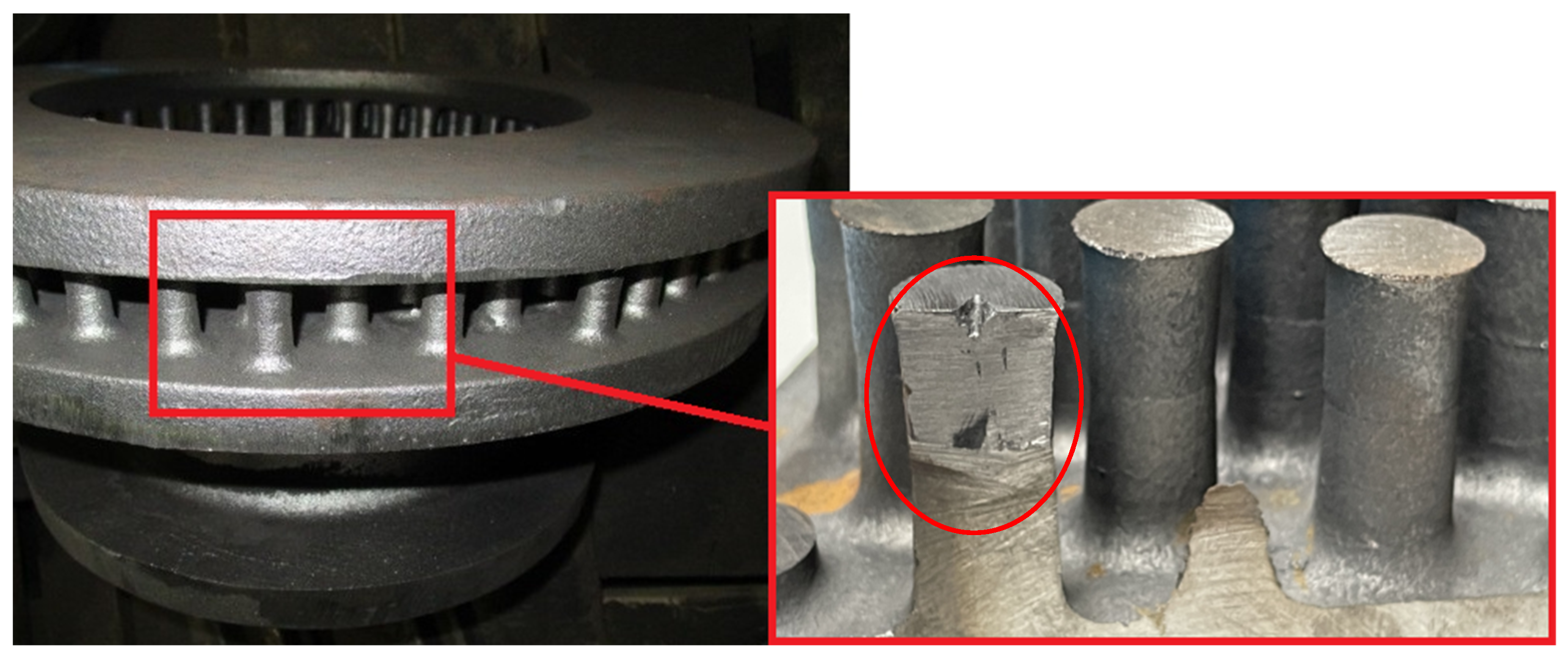
Figure 2.
3D model of a casting brake disc.
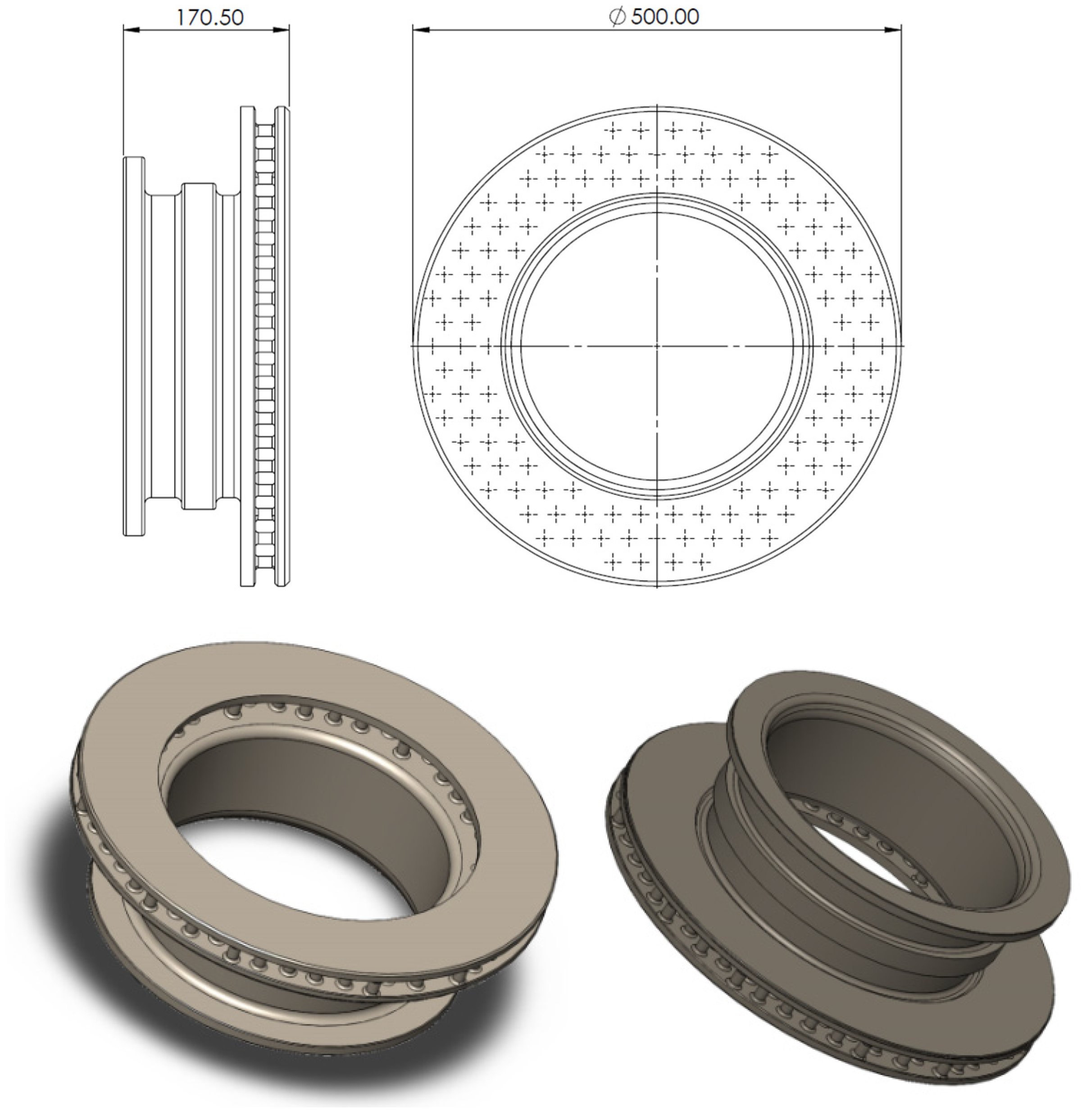
Figure 3.
Gating system.
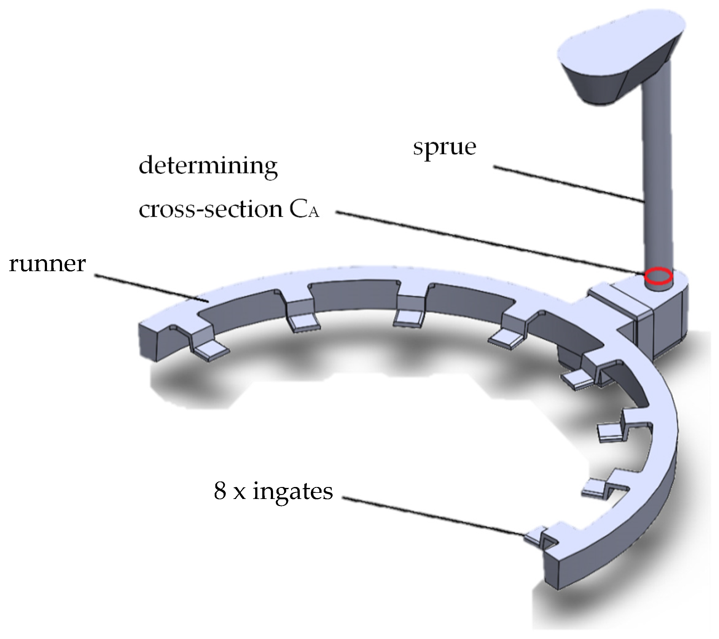
Figure 4.
Casting assembly with gating system and feeders.
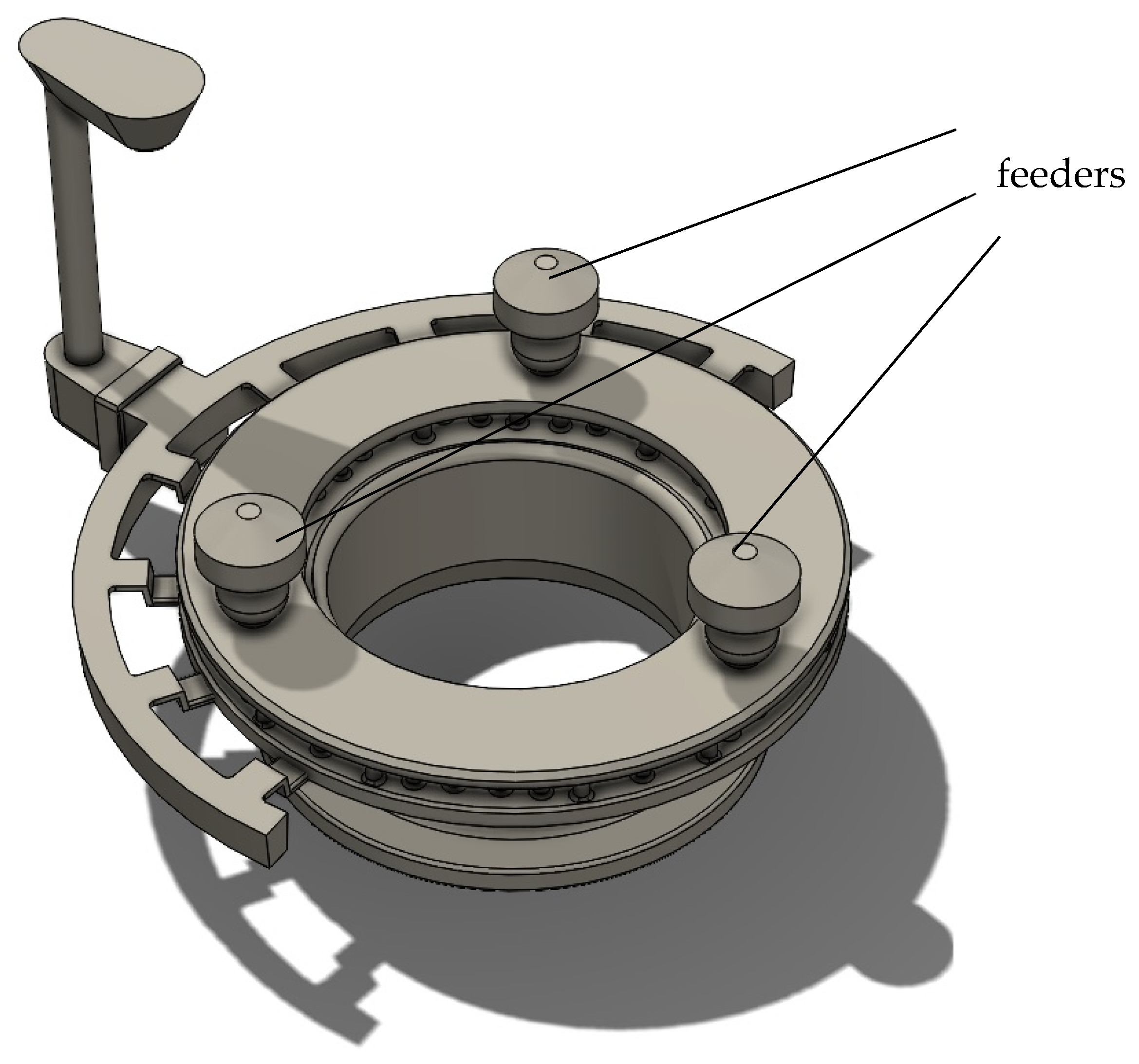
Figure 5.
Schematic of casting and solidification simulation [24].
Figure 5.
Schematic of casting and solidification simulation [24].
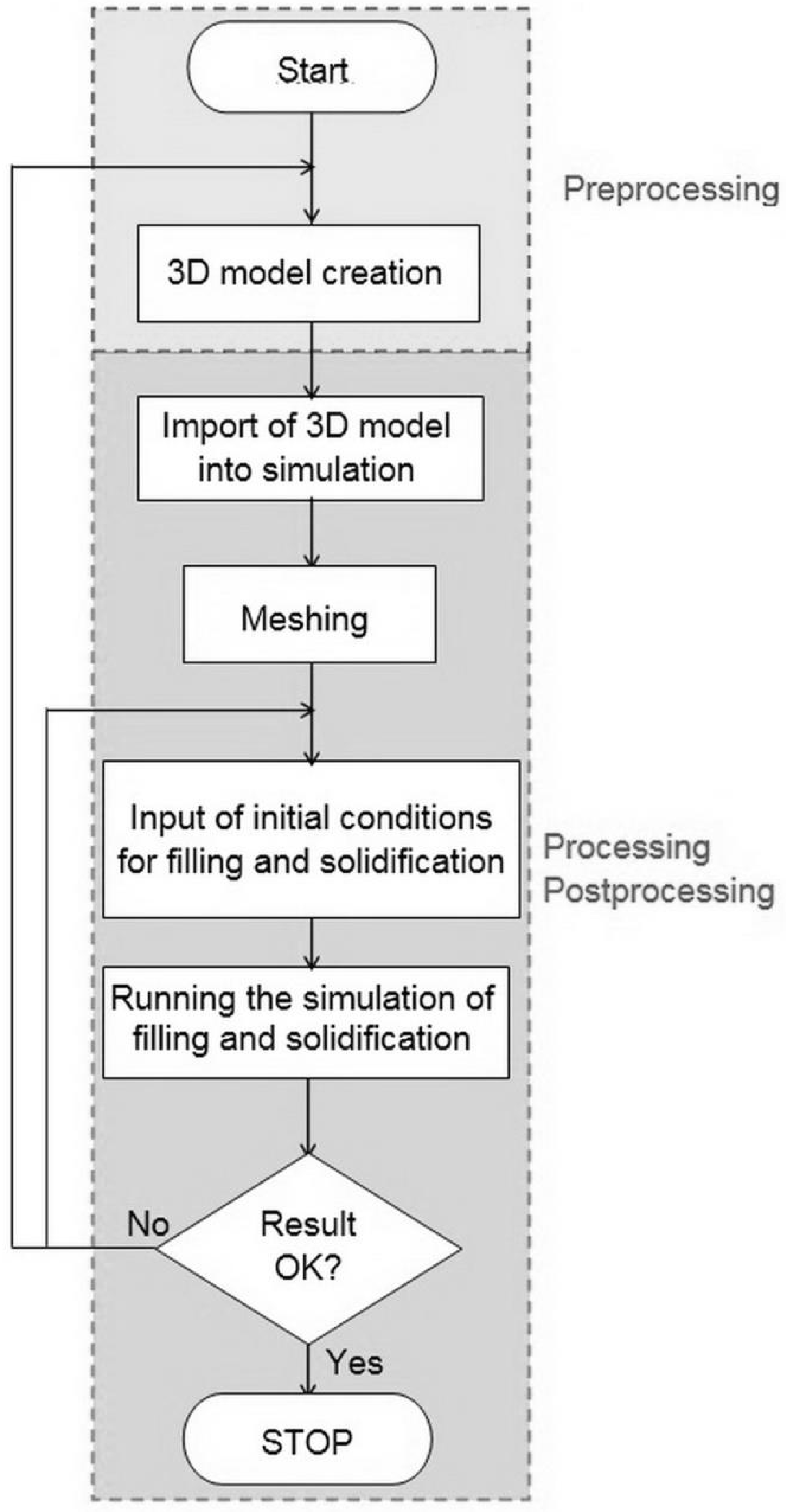
Figure 6.
Detail of mesh.
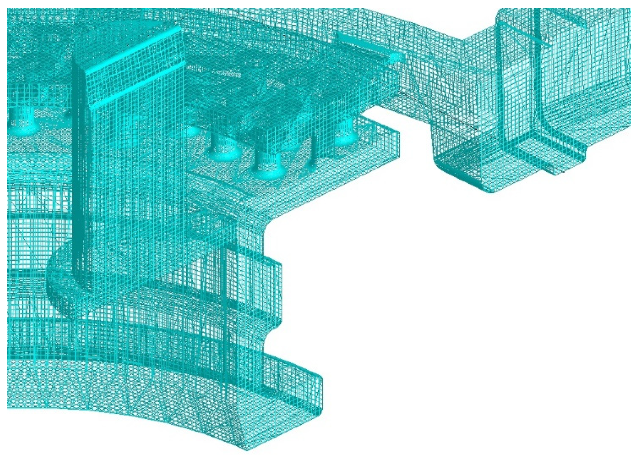
Figure 7.
Filling speed.
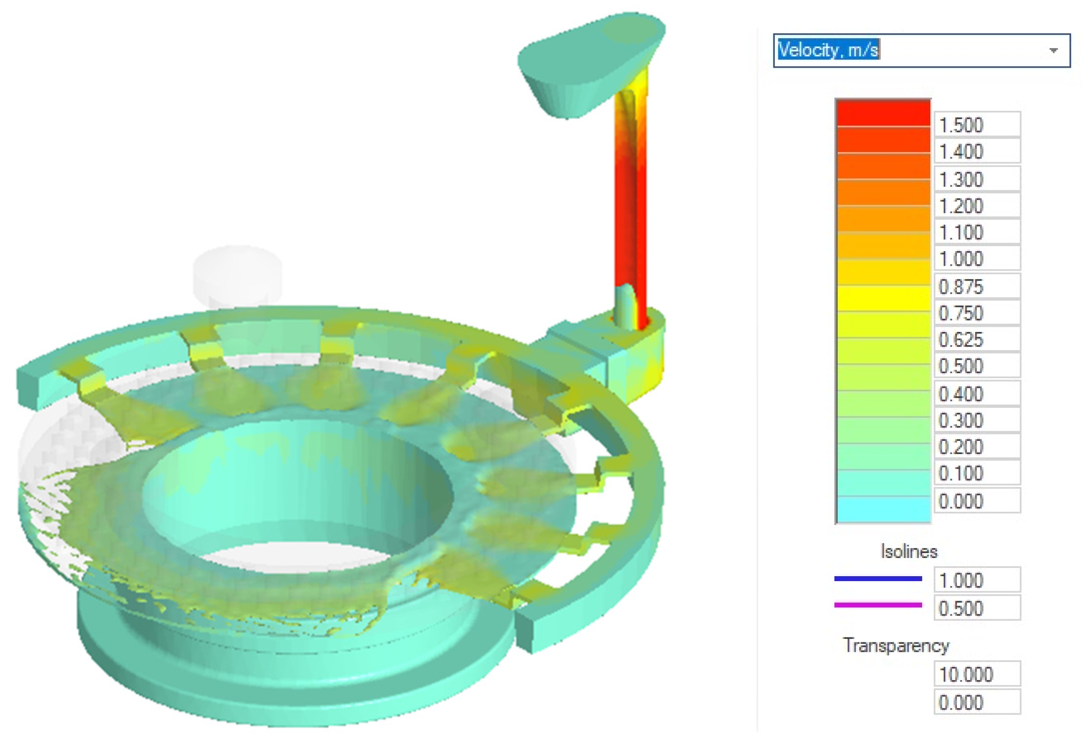
Figure 8.
Prediction of shrinkages in cast.
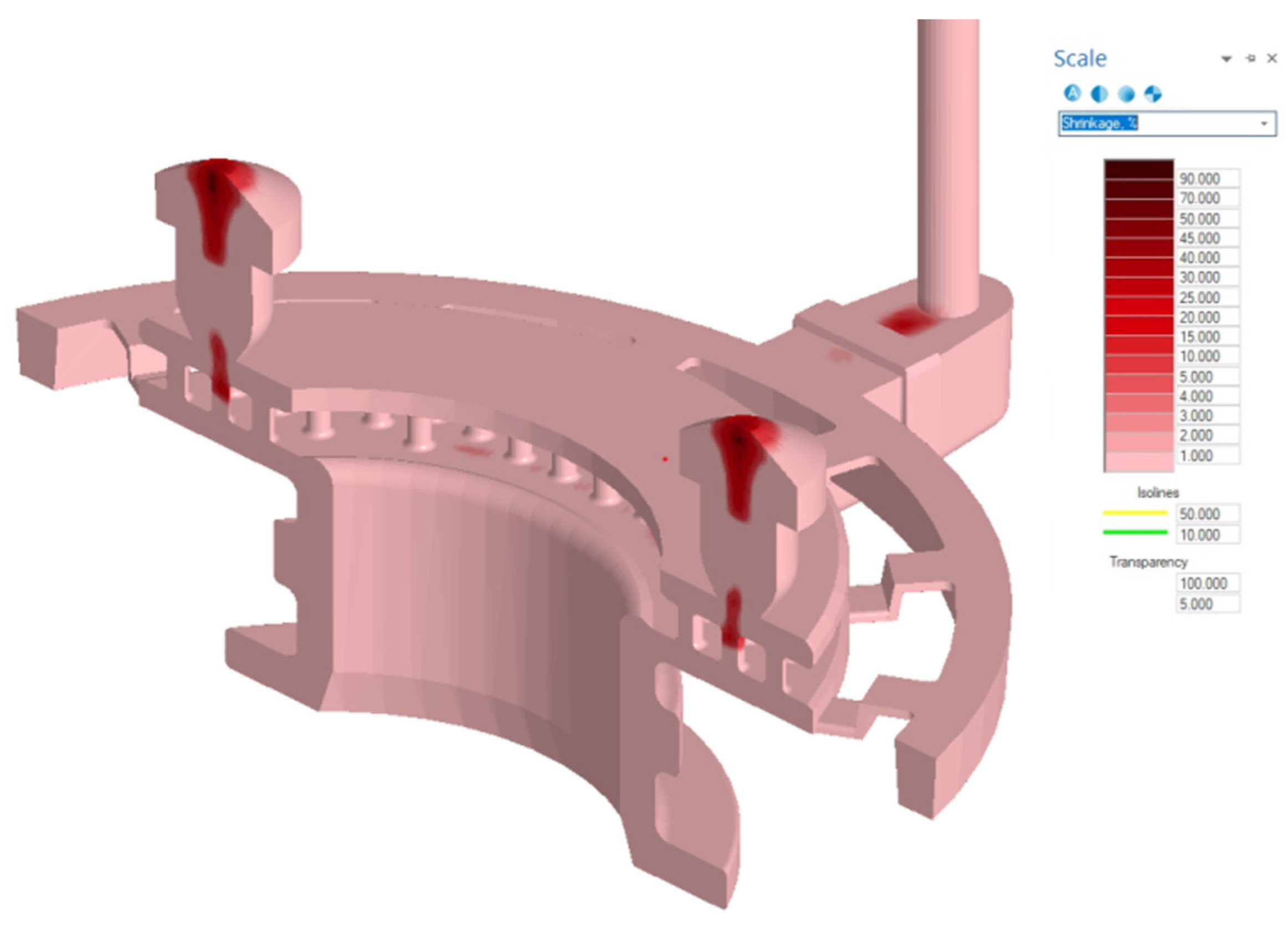
Figure 9.
Detail of shrinkages in cast.
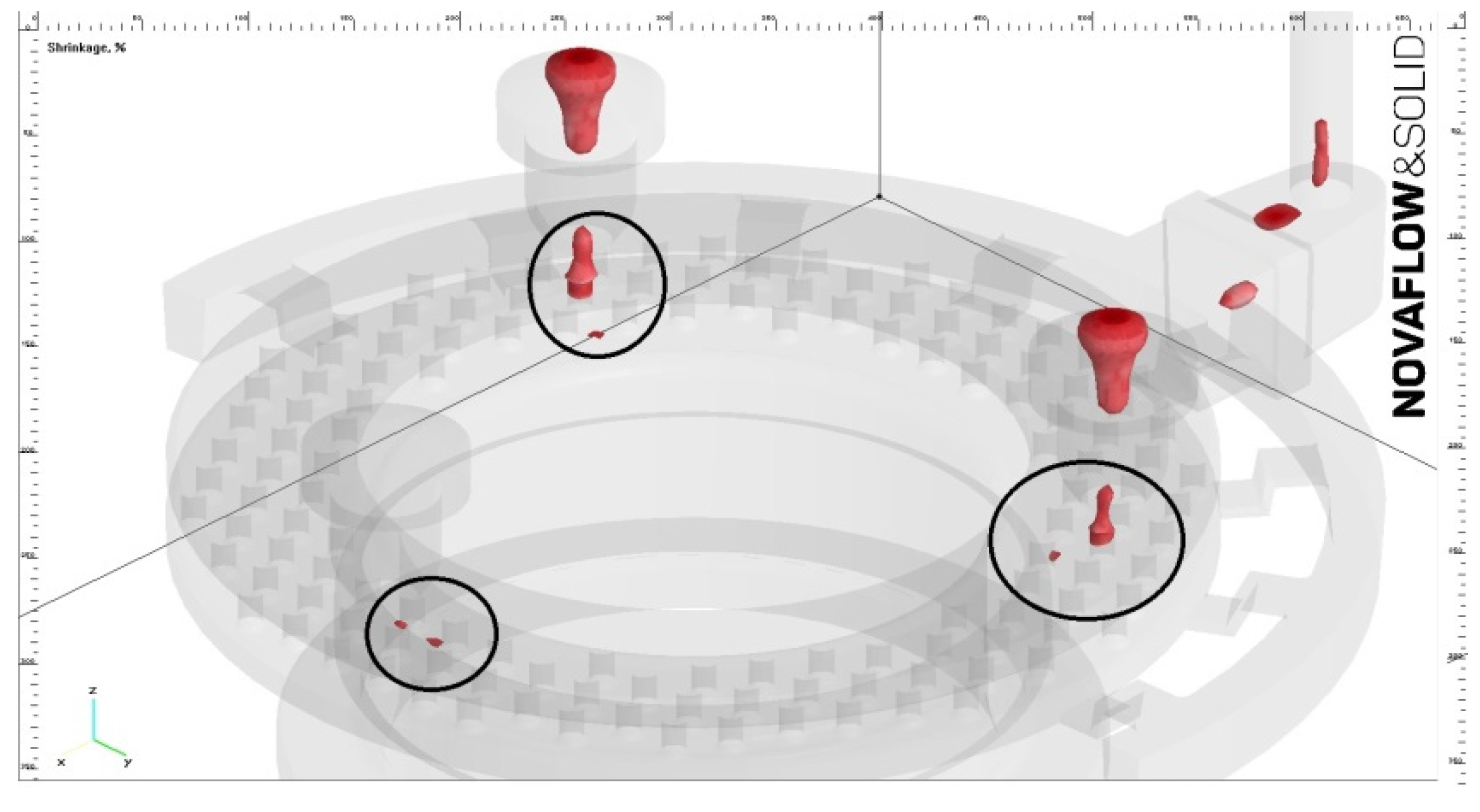
Figure 10.
New assembly with six feeders.
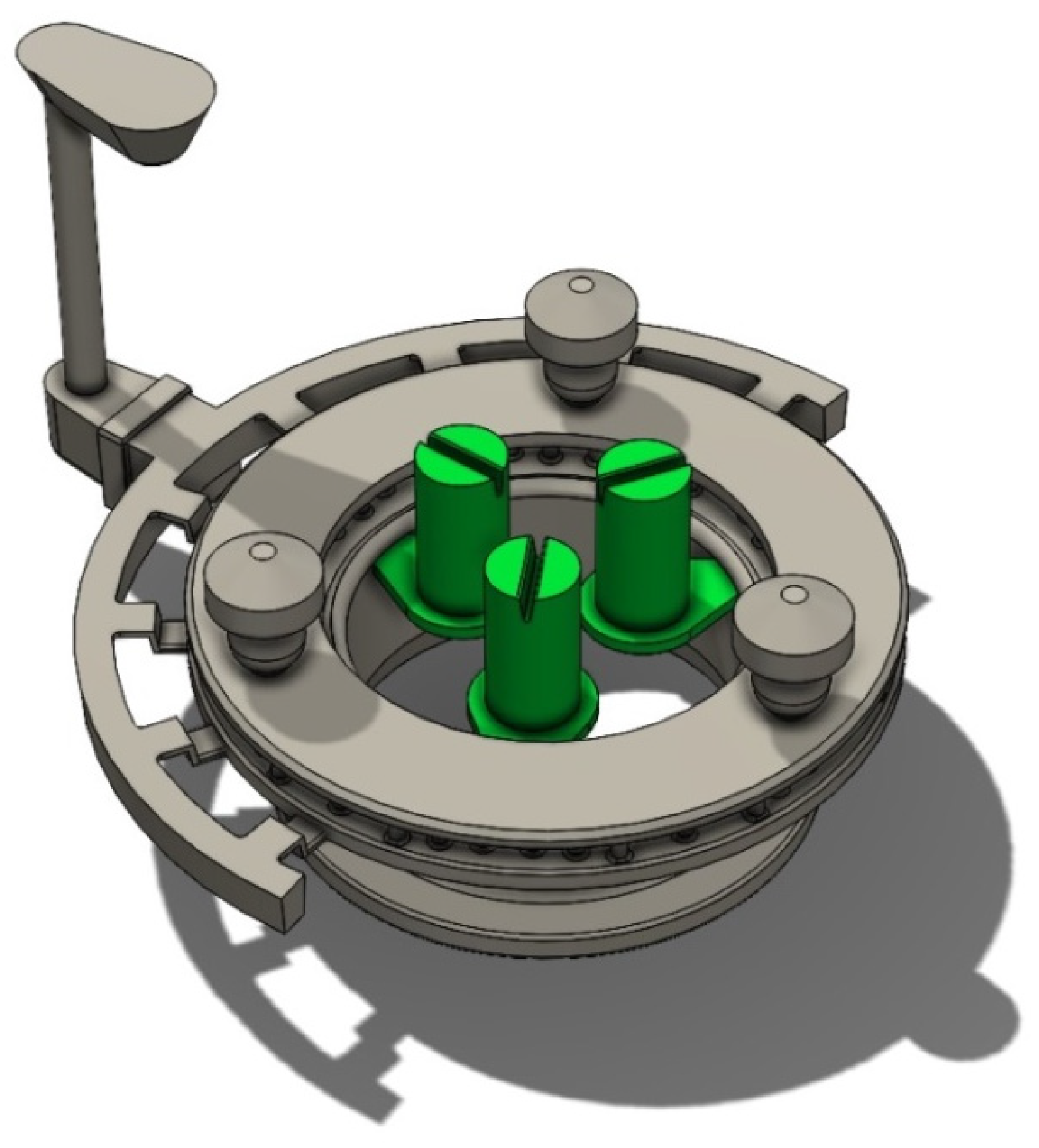
Figure 11.
Filling speed.
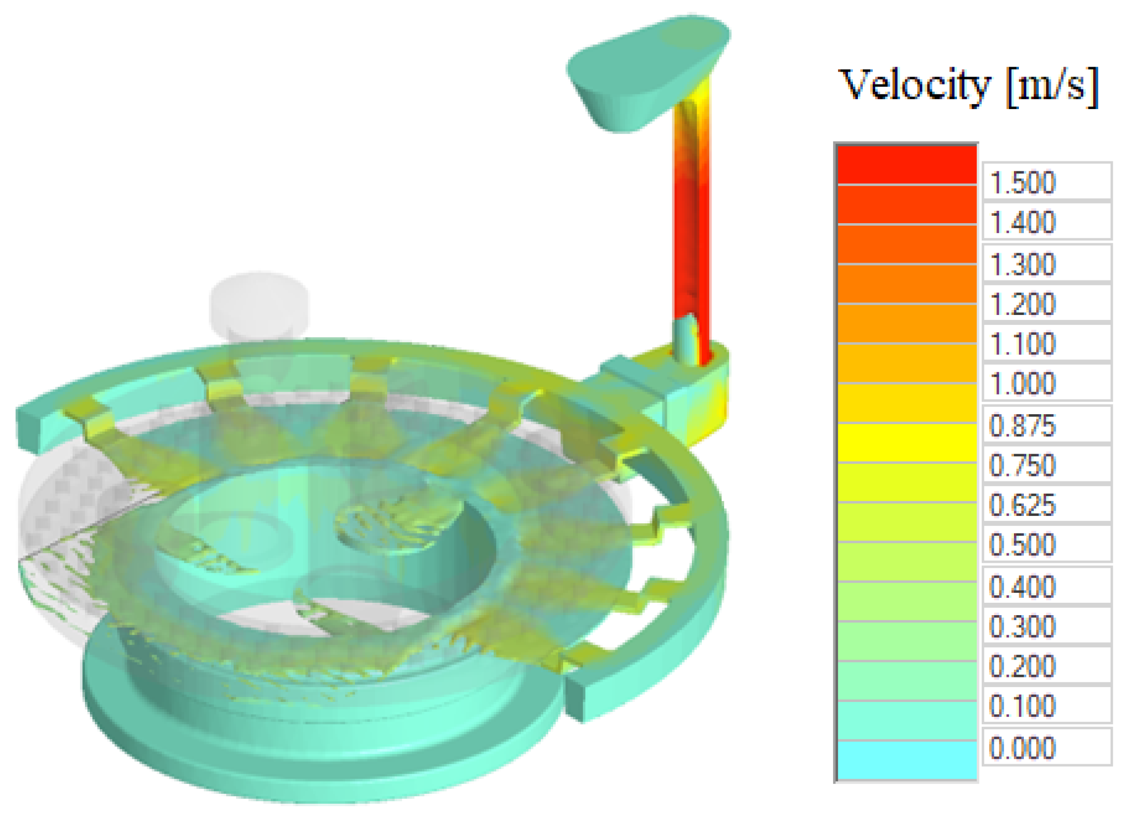
Figure 12.
Prediction of shrinkages in cast.
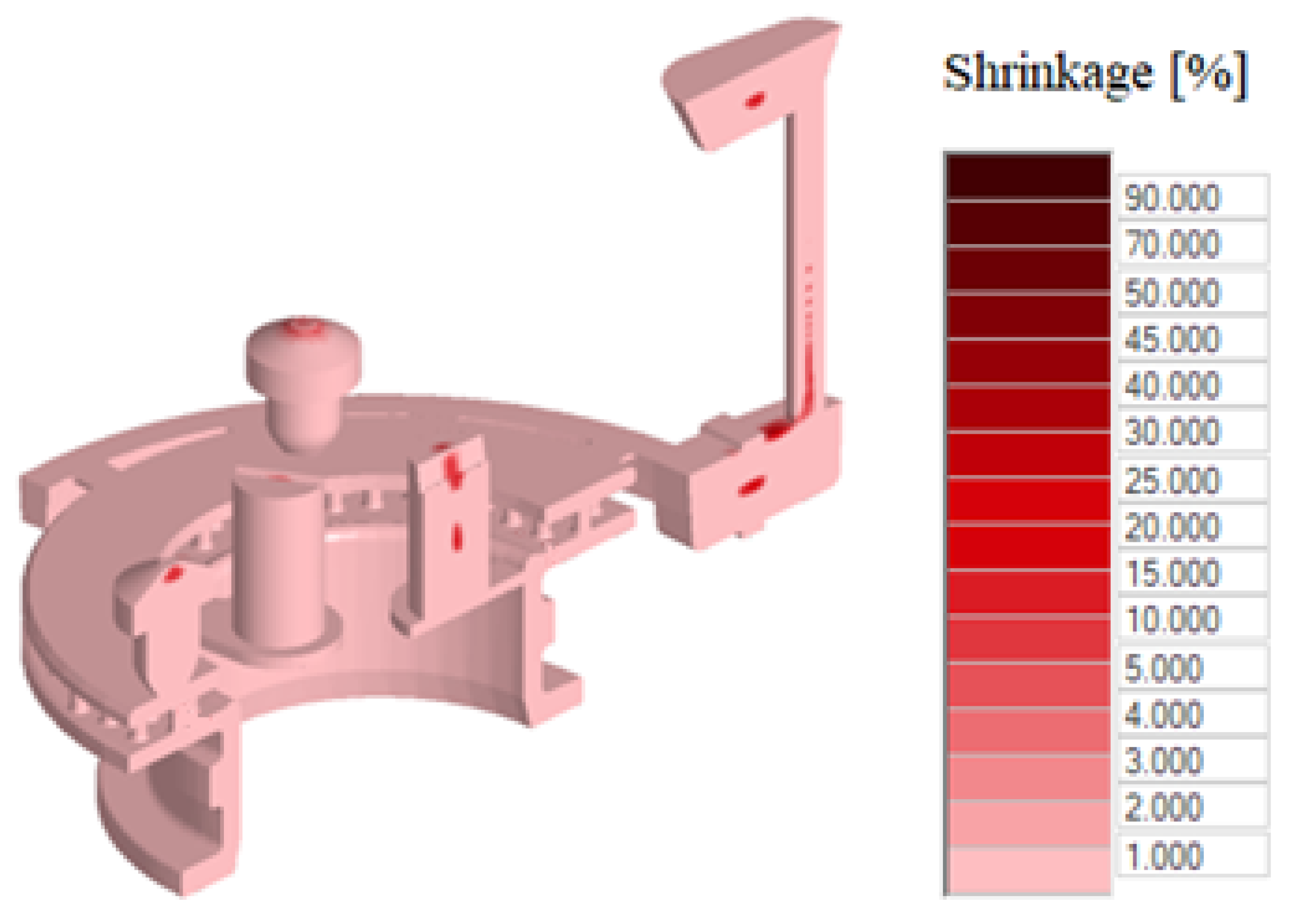
Figure 13.
Detail of shrinkages in cast.
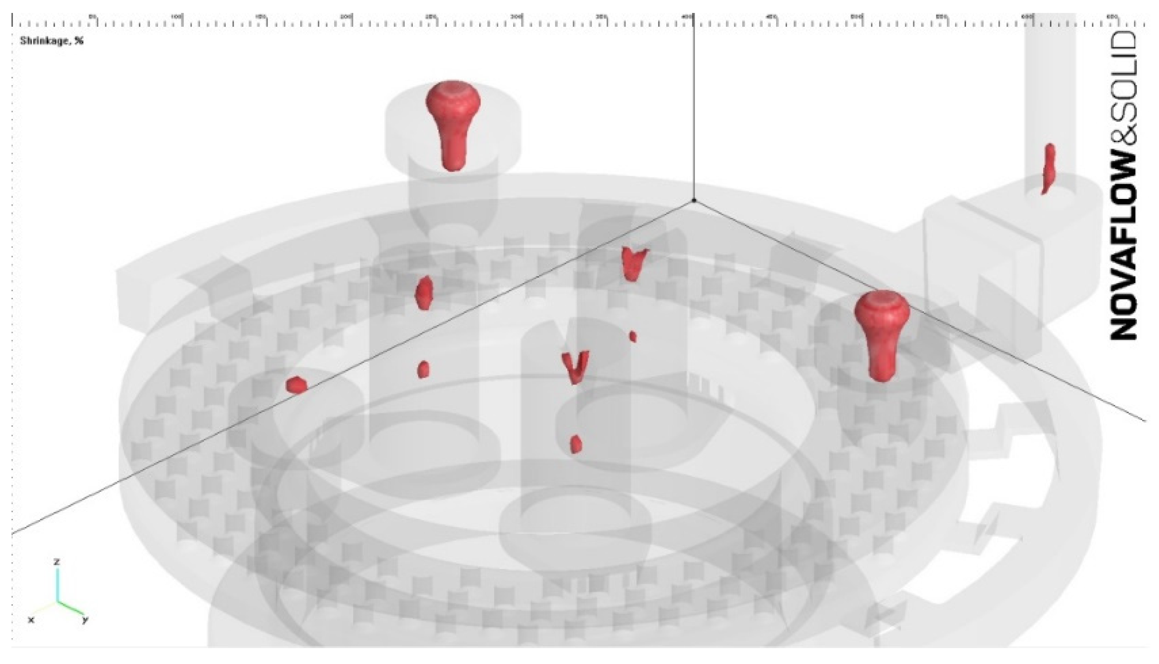
Figure 14.
Cut of the casting in the critical area.
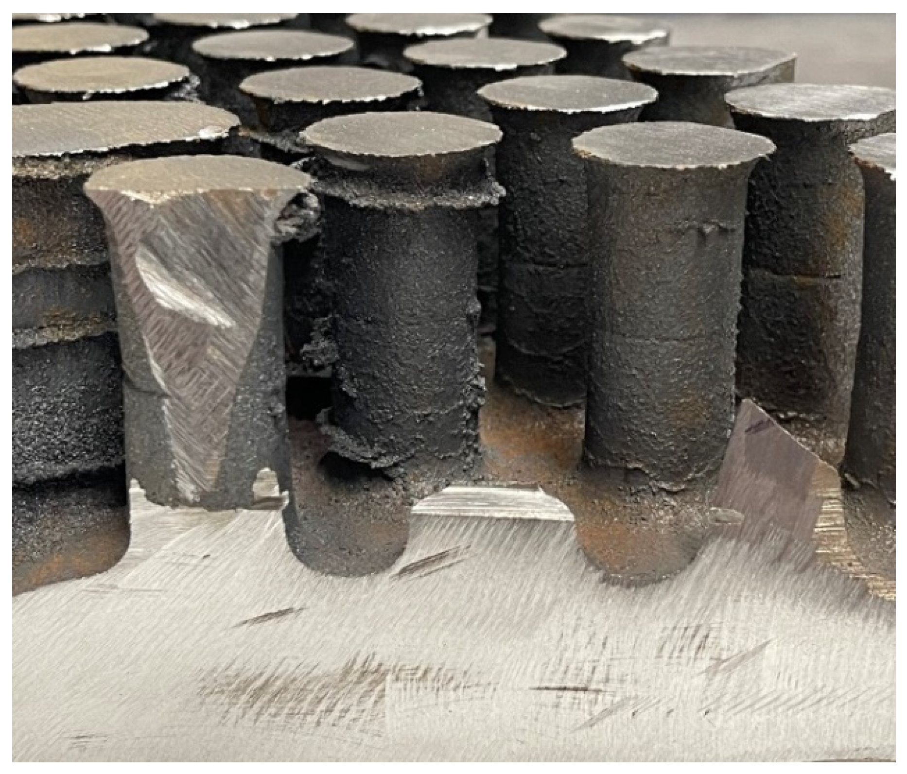

Table 1.
Input data for the computer simulation.
| casting technology | gravity casting |
|---|---|
| alloy | EN-GJS-400-15 |
| flow rate at the ingate | 11 kg. |
| casting temperature | 1382°C |
|
cell size coefficient of flow losses material of mold temperature of mold |
2.5 mm 0.42 Bentonite 23°C |
| number of cells | 5.900.000 |
Disclaimer/Publisher’s Note: The statements, opinions and data contained in all publications are solely those of the individual author(s) and contributor(s) and not of MDPI and/or the editor(s). MDPI and/or the editor(s) disclaim responsibility for any injury to people or property resulting from any ideas, methods, instructions or products referred to in the content. |
© 2024 by the authors. Licensee MDPI, Basel, Switzerland. This article is an open access article distributed under the terms and conditions of the Creative Commons Attribution (CC BY) license (http://creativecommons.org/licenses/by/4.0/).
Copyright: This open access article is published under a Creative Commons CC BY 4.0 license, which permit the free download, distribution, and reuse, provided that the author and preprint are cited in any reuse.


