
Submitted:
16 February 2024
Posted:
19 February 2024
You are already at the latest version
Abstract
The production of high-quality castings without foundry defects at minimal production costs is a constant priority for foundries. Innovation and optimization of production processes are key to achieving this goal. Computer simulation of foundry processes offers a modern alternative to expensive and time-consuming experiments in real foundries and provides a reliable representation and analysis of casting and solidification processes. A detailed analysis of the casting and solidification simulation results allows the prediction of various risks that can cause defects in cast castings, thereby reducing their quality and, last but not least, the cost of their production. The paper deals with the analysis of a computer simulation of the casting of a brake disc in the Slovak foundry. This brake disc has had shrinkages and micro shrinkages that reduce the internal quality of the casting. These defects occurred in the ribs in the upper part of the casting under the feeders. A computer simulation of the casting and solidification of this casting was made according to real conditions. It turned out that the designed ingate system with a system of feeders was not sufficient to eliminate emerging defects. A new layout of the feeders was proposed, which ultimately eliminated the occurrence of defects based on the results of computer simulation. The input parameters were set to be as close as possible to the actual needs of the foundry. 3D models of the assemblies were designed in SolidWorks CAD software, and filling and solidification simulations were performed using the NovaFlow & Solid CV 4.6r42 simulation program.
Keywords:
computer simulation
; casting
; foundry defects
; shrinkage
; gating system
; feeder
1. Introduction
Numerical modeling of the casting process is an important tool in foundry, which is based on the use of empirical and semi-empirical physical and numerical models. These models allow the simulation and analysis of complex processes that occur during the casting process. The use of simulation software with an integrated numerical model makes it possible to obtain sophisticated solutions and data for these processes. Simulation software and correct setting of the input data may positively affect and even eliminate the trial and error method, which has long been used in some foundries. Optimization of the gating system is possible not only to reduce the input costs of the production of a particular series of casts but also the costs associated with the identification of the causes of the defects.
Solidification simulation is one application of numerical modeling that helps identify hot spots in a mold. Flow simulation is another important application that provides visualization of melt velocity during mold filling as well as filling and solidification time information. This information helps us predict and prevent melt flow disturbances and thereby predict the occurrence of defects [1,2].
Melt flow in closed systems can be laminar or turbulent. Laminar flow is maintained up to a certain critical velocity, after which the melt becomes turbulent. In turbulent flow, some of the melt's energy is consumed to form vortices, resulting in reduced overall flow velocity and unsteady fluid flow. In swirling regions, there is an increased flow of liquid metal and a decrease in pressure, which can cause gas particles to be entrained into the melt. These particles cause wear and erosion of the molding compound, being absorbed by the melt much like gaseous particles. These inclusions have a significant impact on the quality of cast parts. The danger of particle entrainment increases as the flow velocity increases to a value of approximately 1.2 m/s at which entrainment damage to the mold is likely. The flow velocity in the notches should be in the range of 0.5 to 1.0 m/s [3,4,5,6].
Most of the defects in the casting and solidification process are caused by incorrect design and placement of the gating system and feeders on the casting. A correctly designed gating system and the placement of castings will ensure optimal filling of the mold cavity, directed solidification of the casting, and the formation of shrinkage in the feeder [7,8]. The formation of shrinkage in the casting is accompanied by negatively directed solidification when the melt is closed in the solidifying part of the casting, i.e. the feeder solidifies earlier than the casting [9].
In addition to the factors mentioned above, which affect the quality of the produced casting, the shrinkage of ductile iron in the solidification process is also an important phenomenon. The occurrence of withdrawals and their causes are addressed by several authors such as Chen et al. [10] and Yeung et al. [11]. Shrinkages occur in the interval liquidus - solidus. Their occurrence can be prevented by replacing the reduced volume from another source - infusion. The problem of shrinkages and feeders is described in detail in [12,13,14]. Using this process, the size of the feeders is chosen based on the volume capacity of the casting and the cast alloy. Subsequently, the shape and dimensions of the feeder are decisive for the choice of the appropriate type of feeder and their correct placement on the casting so that the metal is added to the entire volume of the casting during volumetric shrinkage. The gating system and its opening into the casting also play an important role in this process [15]. The solidification of ductile iron castings and their construction was dealt with by Bjerre et al. [16].
This type of cast is made of Ductile Iron due to its specific properties. Ductile iron is a graphite cast iron with graphite in the shape of spheres embedded in a matrix of an alloy of iron, carbon, and silicon. The carbon level is within the range of 3.40 - 3.90%. The higher values of carbon are typical of thin-section casting. The high Carbon Equivalent (CE) and low solidification rate (thick section) may result in graphite flotation and degeneration of the graphite shape. The risk of flotation is practically inexistent in the thinner section. The recommended level of CE in the thinner section is above 4.2 % (4.3 - 4.7 %) [17]. The formation of spheroidal graphite is achieved by modifying melt cast iron (base phase of gray cast iron, most often of eutectic composition with a lower content of impurities) by pure magnesium or by magnesium alloys Fe-Si-Mg (with 5 – 10 % Mg). To achieve a graphite nodularity, a magnesium content of 0.04 to 0.06 % in ready-to-cast iron is commonly envisaged. Ductile iron has excellent technological properties compared to steel, such as lower melting temperature, better castability, and machinability. The spherical shape of the graphite causes minimal weakening of the metal matrix (minimal notching effect). The mechanical properties approximate the properties of steels. The metal matrix can be ferritic, ferritic pearlitic, and pearlitic. The content of these phases in the structure most importantly determines the mechanical properties of ductile iron. Ferrite is a carrier of toughness and plastic properties, perlite is a carrier of strength and hardness. Bainite, martensite, or austenite can be obtained in the structure by alloying or heat treatment. This cast iron is susceptible to the quality of metallurgical processing and relevant potential for casting defects [18,19].
Volume changes in the casting during solidification (formation of shrinkage) are physical phenomena that cannot be prevented. Through technological intervention, we can ensure the formation of shrinkage in the casting and the casting solidifies in a healthy way. The formation and elimination of shrinkage and micro shrinkage in ductile cast iron was dealt with by Siclari et al. [20], and Davis [21], and its further description is given in [22].
For a casting of a given type, i.e. a casting with different wall thicknesses, positively directed solidification and the correct distribution of feeders on the casting are very important. Several authors dealt with the issues of ductile iron castings with different wall thicknesses and the possibilities of their feedering [23,24].
The paper aims to analyze the causes of shrinkage and microporosity on the rod parts of the cast brake disc casting in the Slovak Foundry using computer simulation. The results of the computer simulation of casting and solidification of the cast with the original configuration of feeders and the newly designed configuration of feeders are presented here. The purpose of the computer simulation is to find out how these adjustments to the placement of the feeders affect the entire casting and reduce or eliminate the occurrence of shrinkage in this part of the casting. Computer simulation is significant in the pre-production stage of casting production to avoid the occurrence of foundry errors on finished castings. Ultimately, this results in a reduction of financial costs and an increase in the efficiency of the production of castings without the occurrence of foundry defects.
2. Materials and Methods
During the production of castings, which are the final semi-finished product of the brake disc, foundry defects occur – shrinkages, which are undesirable and can ultimately lead to damage to the castings. The issue of the given area is very extensive and is the subject of many completed studies and presented works. However, research on this topic is always necessary, as it is often closely related to a specific product. Computer simulation can be applied from several methods and procedures available for further research.
If shrinkage occurs in the casting, its integrity is violated and it may finally break under stress.
Foundry defects - shrinkages that occurred in the casting were caused by incorrect construction of the model device. This created defects and increased production costs. Therefore, it was necessary to perform an analysis of the occurrence of defects using computer simulation, which would solve the given problem.
As it is a highly stressed casting of the brake disc during its operation, where a minimum occurrence of internal defects in the casting is required. Their occurrence causes deterioration of mechanical properties and threatens its functionality.
To analyze and study the process of casting and solidification of the brake disc casting, two simulations were carried out:
- with three feeders - original assembly,
- with six feeders - new assembly.
The casting of the brake disc, for which the gating system was verified, is produced in the Slovak foundry. The casting is made of ductile iron EN-GJS-400-15 (spheroidal graphite iron – SG iron). Its chemical composition is: C 3.60%; Si 2.50%; Mn 0.10%; S 0.01%; P 0.02%; Mg 0.04%; Cu 0.15%. Saturation degree Sc (0.95 – 1.04) was at the customer's request. The weight of casting after processing is 30 kg and its diameter is 500 mm. The casting is made by gravity cast into a bentonite molding mixture.
The problem with this cast is the appearance of shrinkage on the rods in its upper part. X-ray inspection showed shrinkages in this part of the casting. The castings were cut in this part, Figure 1. The occurrence of shrinkages is due to insufficient depositing of metal from the casting during solidification of the casting. For this reason, a computer simulation of casting and solidification was made according to real conditions, and a new distribution and number of feeders per casting was also proposed.
The 3D model of the casting (Figure 2) was created in SolidWorks CAD software from Dassault Systemes. This program has a light and visually clear user environment that offers the creation of 3D and 2D models. The model we created was made in SolidWorks version 2022.
A casting is the initial blank used to manufacture a brake disc. The casting process consists of the gradual filling of the mold cavity with molten metal, while the gating system plays an important role here. An inseparable part of the gating system are feeders, which ensure replenishment of the loss of melt in the process of solidification and shrinkage of the metal. Shrinkage results in linear and volume changes that ultimately lead to shrinkage.
The gating system with a determining cross-section "CA" in the lower part of the sprue is used for casting the disc, Figure 3.
The determining cross-section CA is located at the bottom of the sprue, not in the ingate, as is the case with the vacuum gating system, with a standard ratio: 1 : 1.2 : 1.4 (1 - area of the ingates, 1.2 - area of the runner, 1.4 - area of the sprue). The ingates are located in the lower part of the mold. The gating system always expands towards the casting by at least 10%. The ideal ratio for this type of gating system is 1:1.2:1.4 (1 - the area of the determining cross-section CA, 1.2 - the area of the runner, and 1.6 the area of the ingates). The cast time is not controlled by the filter or the cross-section of the ingates [25,26].
CA is calculated according to Eq. 1:
where: W - Cast weight [kg]
δ - Density [g/cm3]
ξ - Friction factor
t - Cast time [s]
H - Effective pouring height [cm]
The cast time was calculated according to Eq. 2:
where: β – average thickness of the casting walls
W – Weight of crude casting [kg]
The cast time was 18 seconds. The coefficient β of 0.31 was chosen for cast iron. The effective casting height H of the mold depends on the dimensions of the casting and the type of gating system, Eq. 3:
where: H – effective metallostatic height [cm]
h – height difference between the level of the melt in the pouring basin and the center of the ingates height [cm]
P – height of the casting above the ingate [cm]
C – height of the casting in mold [cm]
The determining cross-section of the CA was calculated at 9.36 cm2. The calculated determining cross-section serves as a basis for determining the cross-sections of other elements of the gating system. Based on the above ratio, the individual elements of the gating system were calculated as follows:
- CA – 9.36 cm2 -> diameter of sprue 2.89 cm
- runner – 1.2 x CA = 11.23 cm2
- sprue – 1.2 x 1.2 x CA = 13.47 cm2
The complete original assembly of the gating system, feeders, and casting is shown in Figure 4. The casting is cast using three feeders that are placed in the upper part of the casting. The problem of feeders is described in more detail in literature [11,12,13,14,15,16].
The cast and solidification simulation process is based on the block diagram (Figure 5) previously published in [27]. The whole process is divided into two basic parts and saccessive steps that follow each other.
In the first step, a 3D model is created, which is transferred to the simulation program. A simulation mesh is then created in it. The creation of a simulation mesh, especially the size of the individual cells of the mesh, significantly affects the quality of the obtained results, the requirements for hardware equipment, and the time required to perform the calculation.The mesh should be chosen so that at least two cells fit at the narrowest point on the cast.
The computer simulation of the original assembly was done in the program NovaFlow & Solid CV 4.6r42 from the Swedish company Novacast. This software uses New meshing technology and new advanced numeric models, Control Volume Meshing (CVM). CVM Technology allows the surface of the 3D model to control the shape of the mesh elements on the border of the casting. This creates cubic elements inside the casting as well as border cells on the boundary of the casting.
CVM technology has the following advantages in comparison with FDM/FEM methods [28]:
- -
- For most castings, simulation time is reduced to around 10 percent with the same or improved accuracy (FDM),
- -
- A higher accuracy in simulation, thanks to a perfect description of the 3D model. All sections are correct in size (FDM),
- -
- Needs less cells to define the casting geometry and ensures faster simulations and smaller result files (FDM),
- -
- The meshing process is completely automatic and only takes seconds (FEM),
- -
- Enables more advanced calculations, such as gas flow, contact task (stress), or full mold process (FDM).
The program is optimized for foundry processes, especially for gravity cast in sand molds, compared to the commonly used AnsysFluent software, which is used for general fluid flow processes (CFD). Compared to the MagmaSoft and ProCast software, it is more affordable. It also has excellent customer support. This program offers options for setting the geometry of the cast, hydrodynamic simulation of filling processes in various technological modes, taking into account the presence of a free surface of gas bubble formation, as well as simulation of solidification processes, taking into account the transfer of heat and mass between different phases. Based on the obtained calculations, metal shrinkage, misruns, and other foundry defects are predicted [25].
NovaFlow&Solid calculates turbulence according to Prandtl's mixing length theory, Eq. 4, Eq. 5 [28]:
where: u - melt velocity.
– rate of speed change across the main flow
l – Prandtl’s mixing length
k – turbulence koeficient (0.39) in our case
After importing the 3D model, the cellular net was determined (the more cells, the more accurate the results). The total number of cells for the original assembly is shown in Table 1.
The detail of the mesh is documented in Figure 6.
The input data for the simulation is documented in Table 1. These input data correspond to the real operating conditions of the foundry.
The properties of the cast material EN GJS 400-15 from the database of the simulation program are documented in Table 2.
3. Simulation results of the original assembly
The filling process is shown in Figure 7. With the given type of gating system, the filling speed was in the range of 0.42 – 0.65 m/s during the entire period. The given value is within the prescribed range given by the literature [3] and thus there was no swirling of the melt during filling.
The simulation of the solidification of the casting pointed to the occurrence of shrinkage, Figure 8. The probability of occurrence of shrinkages in the casting based on the simulation results is more than 90%. According to the assumption, the shrinkages were formed in the castings, but what is inadmissible they were also formed in the ribbed rod part of the casting.
The details of the shrinkages that occur in the rod parts of the casting after the results of the simulation of the original assembly are documented in Figure 9. Other shrinkages occur in the feeders and parts of the gating system. Their occurrence does not affect the quality of the casting.
4. Simulation results of the new assembly
Due to the construction of the mold and the cast technology, the gating system could not be changed. Only the number and placement of the feeders could be changed. The size and number of feeders were adjusted according to the volume of heat nodes on the casting. Feeders are a critical part of the gating system. The system is based on the solidification behavior of iron with graphite and while graphite is being formed, there is an expansion that should be used for self-feeding of the casting. The expansion is always connected with a pressure increase within the system which, in turn, has to be controlled. If the pressure creates a mold deformation, there is a volume increase that has to be again compensated for, or porosity will be found in the casting [17,29].
The general equation (Eq. 6) for calculating the modulus of the feeder is [27]:
where: MN – modulus of the feeder
f – factor related to the casting modulus
MS – modulus of a segment of the cast
To eliminate shrinkages, a feeder system was placed on the casting, consisting of three feeders on the brake upper surface of type - body 220/25 with a diameter of D 410 mm and three feeders placed in the lower part of the type - FSDP with side necks up to a diameter of D 289 mm, see Fig 10. The total volume of feeders was 2.2 dm3.
The new assembly with the distribution of six feeders is shown in Figure 10.
The input data for the simulation were the same (see Table. 1, Table 2). Only the number of cells of simulation mesh was greater, due to the additional three feeders. The number of cells of simulation mesh was 6 150 000.
The filling speed of the mold cavity in this new six feeders assembly was in the range of 0.42–0.65 m/s [3], as shown in Figure 11. The speed color scale is shown in Figure 7. The stated speed at the entrance to the mold cavity was within the range recommended in the literature. Since the gating system was not changed, but only the feeders were added, this fact could be expected.
Based on the results of the solidification simulation and the prediction of the occurrence of shrinkage, it was shown that the addition of feeders to risky places on the casting had a positive effect. Shrinkages were formed only in the castings and in the gating system, which solidified after filling the mold. The prediction of shrinkage in the casting itself was less than 1%. The details of the resulting shrinkages in the feeders and parts of the gating system are shown in Figure 12 and Figure 13. Their occurrence in the given areas was more than 90%.
Based on the results of the simulation, a series of test castings were cast with a new distribution of feeders. As it turned out, the assembly we designed with the addition of three additional feeders was correct (a total of six feeders), as evidenced by a section of the casting in the critical area where shrinkage occurred, see Figure 14. Figure 14 is just one of many that have been analyzed. The castings were subjected to X-ray testing before they were cut. We do not have permission to publish these images, so they are not included in the article. Since shrinkage in the given area in the original assembly occurred on every casting cast in the foundry, this analysis and the new distribution of the feeders will significantly reduce the cost of production of castings.
The metallographic analysis is performed for a given casting based on the customer's requirements from the area under the feeders. From its analysis, it follows that the structure is 100 % ferritic, and nodularity was 93%, Figure 15.
5. Conclusion
Based on the computer simulation results of the foundry processes, the cause of the defects - shrinkages in the casting of the brake disc made of ductile iron - was determined. An analysis was made of the casting of the original assembly, i.e. the gating system and the location of the feeders. In the original assembly, three feeders were placed, which were insufficient and caused shrinkage cracks on the ribbed roller part of the casting. These shrinkages were not due to poor directed solidification and flow and solidification rates in the mold cavity. As it turned out from the results of the computer simulation, their cause was the insufficient number and location of the feeders. Therefore, it was not necessary to change the gating system, but only the distribution and number of feeders. From the available literary sources, which relate to casting and the formation of shrinkage in ductile cast iron [11,12,13,14,15] and their study, a new arrangement and number of feeders on the casting was proposed. Their number was changed to a total of 6 feeders. These were placed in the central part of the casting. These changes were incorporated into the assembly, which was redrawn in 3D form and then transferred to the NovaFlow & Solid simulation program. Since the number of feeders has changed, the density of the mesh has also changed, and thus the number of cells in the simulation program. The casting input values that corresponded to the operating conditions of the foundry for the simulation program remained unchanged. As the results of the computer simulation showed, these changes brought a positive impact. Shrinkage did not occur in the casting and was created in the feeders. Based on the simulation results, a series of castings with a new feeder layout was cast. In the given test series, these shrinkages did not occur and the correctness of the gating system proposed by us with the new layout and number of feeders was confirmed.
The given analysis also shows the importance of connecting practice, practical experience, and professional scientific knowledge, which were used here. These results will apply to the casting of a similar type of casting.
Author Contributions
Conceptualization, P.F. and A.P.; data curation, P.B., V.S., and P.F.; formal analysis, A.P. and M.B.; funding acquisition, A.P.; investigation, P.B. and P.F.; methodology, P.F. and M.B.; project administration, A.P.; resources, P.F.; Software, P.B. and P.F.; Supervision, P.F.; validation, J.P. and A.P.; writing – original draft, P.F., A.P., and M.B. All authors have read and agreed to the published version of the manuscript.
Funding
This work was supported by the Scientific Grant Agency of The Ministry of Education of the Slovak republic No. KEGA 018TUKE-4/2022, VEGA 1/0002/22 and APVV-22-0580, APVV-21-0142, Polish Ministry of Science and Higher Education Grant No. 16.16.170.7998.
Institutional Review Board Statement
Not applicable.
Informed Consent Statement
Not applicable.
Data Availability Statement
Not applicable.
Acknowledgments
Not applicable.
Conflicts of Interest
The authors declare no conflicts of interest.
References
- Zexuan W., Tao H., Yong Y. & Yan L. (2015). Application and development of numerical simulation technology in Casting. International Journal of Research in Engineering and Science (IJRES), 3(2), 23–28. Retrieved from https://www.academia.edu/12390402/Application_and_development_of_numerical_simulation_technol-ogy_in_Casting?sm=b (accessed 26.02.2021).
- Ha J., Cleary P., Alguine V. & Nguyen T. (1999). Simulation of die filling in gravity die casting using SPH and MAGMAsoft. In: Second International Conference on CFD in the Minerals and Process Industries, CSIRO, Melbourne, Australia, 6–8 December, 423–428. Retrieved from http://www.cfd.com.au/cfd_conf99/papers/045HA.PDF (accessed 5.02.2021).
- Campbell, J.: Complete Casting Handbook Metal Casting Processes, Metallurgy, Techniques and Design, Second Edition, 2015, ISBN: 978-0-444-63509-9.
- Hlebova, S., Ambrisko, L., Pesek, L.,: Strain Measurement in Local Volume by Non-Contact Videoextensometric Technique on Ultra High Strength Steels, Key Engineering Materials, 2014, Vol. 586, pp. 129-132. [CrossRef]
- Pribulova, A.: Influence of Blowing of Argon on the Cleanness of Steel, Archives of Foundry Engineering, 2012, Vol. 12, pp. 91 – 94. [CrossRef]
- Malindzak, D., Saderova, J., Vitko, D., Malindzakova, M., Gazda, A.: The methodology and model for in-process inventories calculation in the conditions of metallurgy production. 2015. In: Metalurgija.
- Olofsson J., Salomonsson K. & Svensson I.L. (2015). Modelling and simulations of ductile iron solidification-induced variations in mechanical behaviour on component and microstructural level. IOP Conference Series: Materials Science and Engineering, 84, 12026. [CrossRef]
- Sertucha, J., Lacaze, J.: Casting Defects in Sand-Mold Cast Irons—An Illustrated Review with Emphasis on Spheroidal Graphite Cast Irons, Metals, 2022, 12(3), 504. [CrossRef]
- Socha, L. et al.: 2022 IOP Conf. Ser.: Mater. Sci. Eng. 1243 012008. [CrossRef]
- Q. Chen, E.W. Langer, P.N. Hansen, Volume change during the solidification of SG iron: comparison between experimental results and simulation, J. Mater. Sci. 32 (1997) 1825–1833. [CrossRef]
- C.. Yeung, H. Zhao, W.. Lee, The Morphology of Solidification of Thin-Section Ductile Iron Castings, Mater. Charact. 40 (1998) 201–208. [CrossRef]
- H. Hou, G.W. Zhang, H.K. Mao, J. Cheng, A New Prediction Way to Shrinkage Cavity Formation for Ductile Iron Castings, Mater. Sci. Forum. 575–578 (2008) 127–134. [CrossRef]
- L.I. Jiarong, B. Liu, Study of solidification shrinkage of ductile iron in dry sand molds, J. Mater. Sci. Technol. 15 (1999) 245–250.
- Larranaga, J.M. Gutierrez, a Loizaga, J. Sertucha, R. Suarez, A Computer-Aided System for Melt Quality and Shrinkage Propensity Evaluation Based on the Solidification Process of Ductile Iron, Trans. Am. Foundry Soc. 116 (2008) 547–562.
- http://www.sorelmetal.com/en/publi/Gating-risering/Gating-Risering.pdf, (n.d.).
- M. Bjerre, N.S. Tiedje, J. Thorborg, J.H. Hattel, Modelling the solidification of ductile casting iron parts with varying wall thicknesses, IOP Conf. Ser. Mater. Sci. Eng. 84 (2015) 12038. [CrossRef]
- The Sorelmetal Book of Ductile Iron, Rio Tinto Iron & Titanium Inc., Montreál (Québec) Canada (2004).
- Sylvester O. Omole, Akinlabi Oyetunji, Kenneth K. Alaneme, Peter A. Olubambi, (2020) Structural characterization and mechanical properties of pearlite – Enhanced micro-alloyed ductile irons. Journal of King Saud University - Engineering Sciences, Volume 32, Issue 3, Pages 205-210 Doi: https://www.sciencedirect.com/science/article/pii/S1018363918303805.
- Pribulova, A., Futáš, P., Pokusová, M., (2020) Influence of charge composition on EN-GJS-500-7 ductile iron properties in foundry operating conditions. Materials Science Forum, 8th International Conference on Material Science and Engineering Technology, ICMSET 2019Singapore19 October 2019 through 21 October 2019. Volume 998 MSF, Pages 42 – 47. [CrossRef]
- R. Siclari, T. Margaria, E. Berthelet, J. Fourmann, Micro-shrinkage in Ductile Iron / Mechanism & Solution, in: Keith Millis Symp. Ductile Casting Iron, 2003: pp. 1–6.
- S.H. Davis, Theory of solidification, Cambridge University Press, Cambridge, 2001.
- http://www.hnsa.org/resources/manuals-documents/single-topic/foundry-manual/, (n.d.).
- K.M. Pedersen, N. Tiedje, Temperature measurement during solidification of thin wall ductile casting iron. Part 1: Theory and experiment, Measurement. 41 (2008) 551–560. [CrossRef]
- P.K. Basutkar, C.R. Loper Jr, C.L. Babu, Solidification of Heavy Section Ductile Iron Castings, AFS Trans. 78 (1970) 429–435.
- Foseco, Foundryman's handbook, 10th Edition, 2000, ISBN: 0-7506-1939-2.
- Futas, P., Malik J.: Technická príprava výroby odliatkov, 2006, ISBN: 80-8073-612-X.
- Futas, P., Pribulova, A., Fedorko, G., Molnar, V., Junakova, A., Laskovsky, V.: Failure analysis of a railway brake disc with the use of casting process simulation, Engineering Failure Analysis, 2019, vol. 95, p. 226 – 238. [CrossRef]
- Novacast (2018). Release of NovaFlow&Solid 6.4. Retrieved from https://www.novacast.se/news/release-of-novaflowsolid-6-4/(accessed 1.02.2021).
- Elliott, R.: Cast Iron Technology, Butterworth & Co. Ltd (1988).
Figure 1.
Shrinkages in the casting.
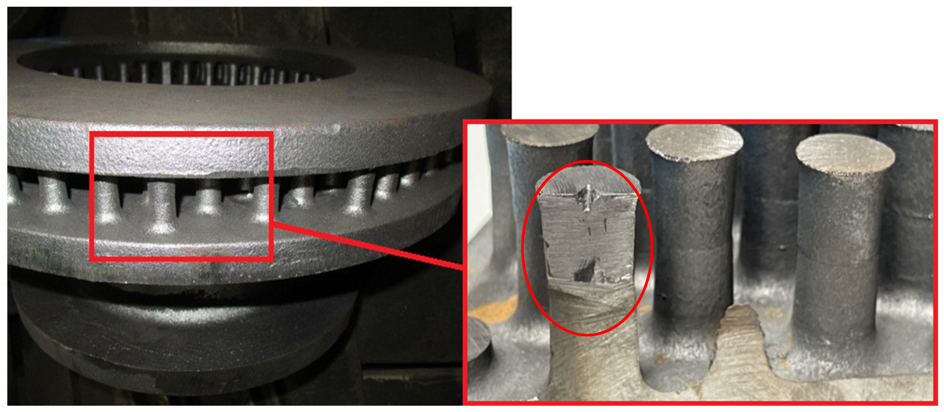
Figure 2.
3D model of a casting brake disc.
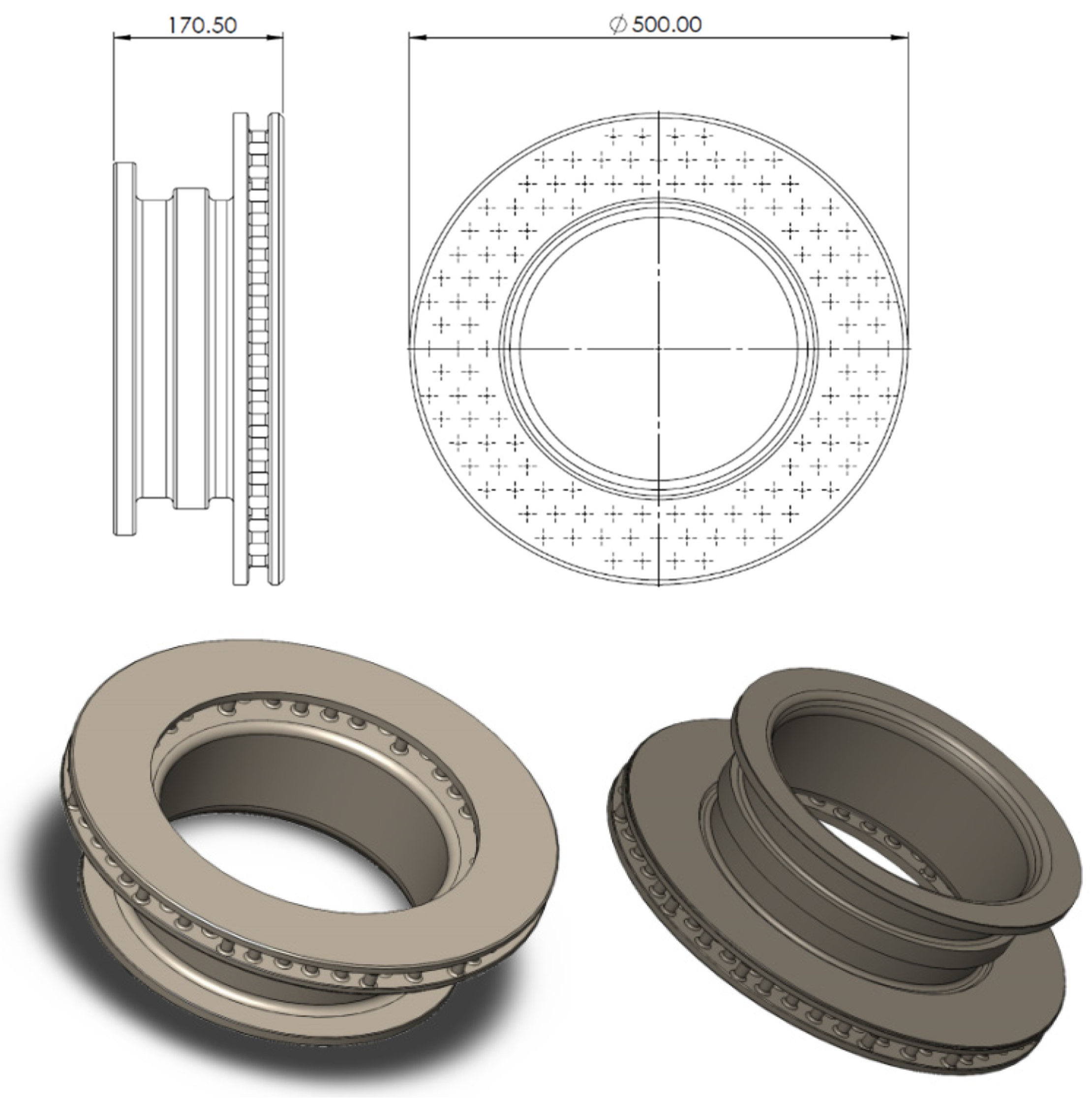
Figure 3.
Gating system.
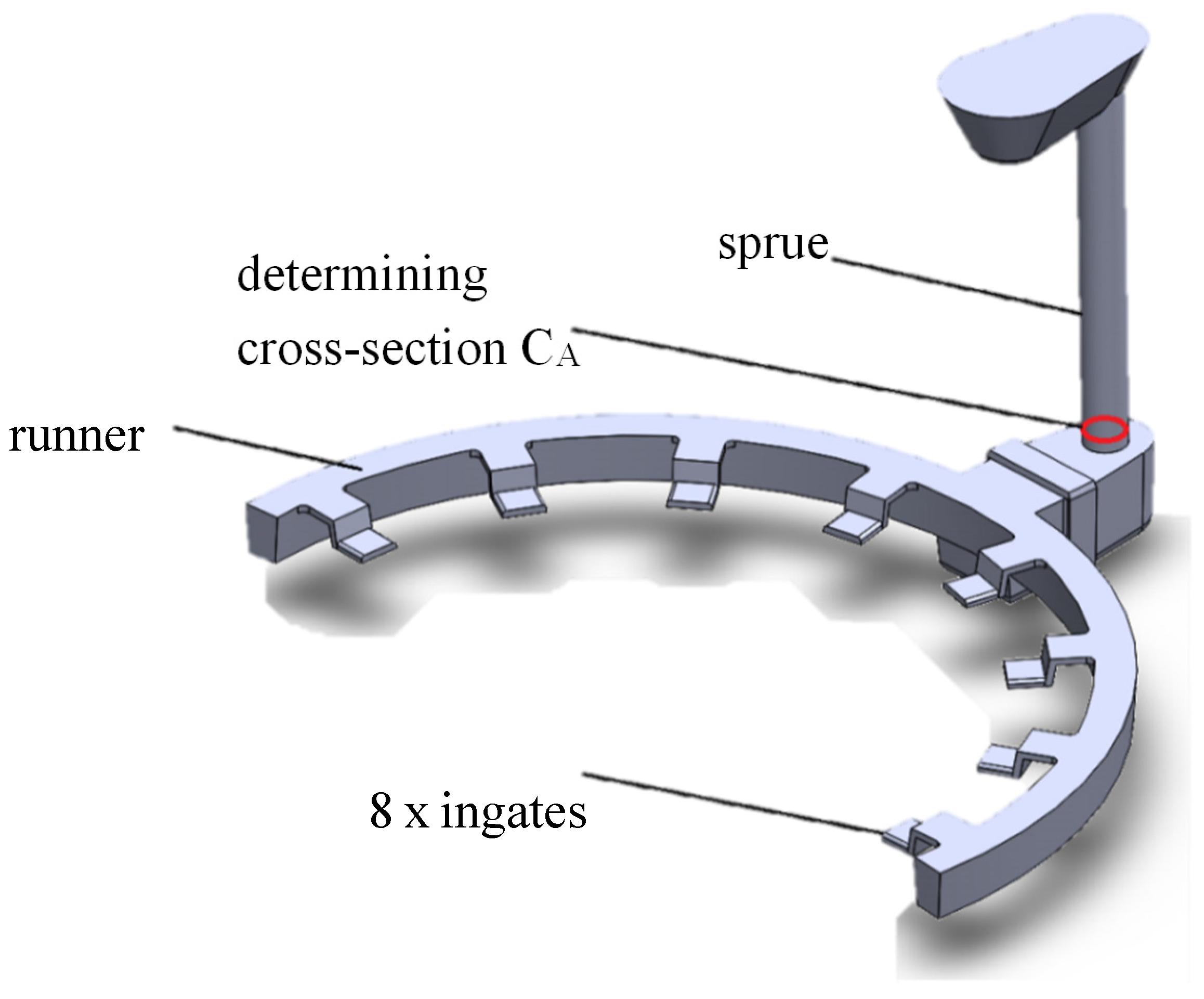
Figure 4.
Casting assembly with gating system and feeders.
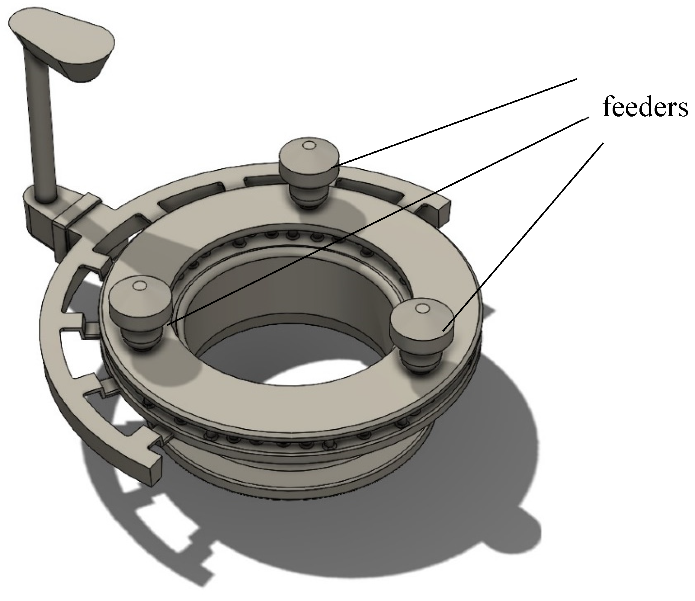
Figure 5.
Schematic of cast and solidification simulation [27].
Figure 5.
Schematic of cast and solidification simulation [27].
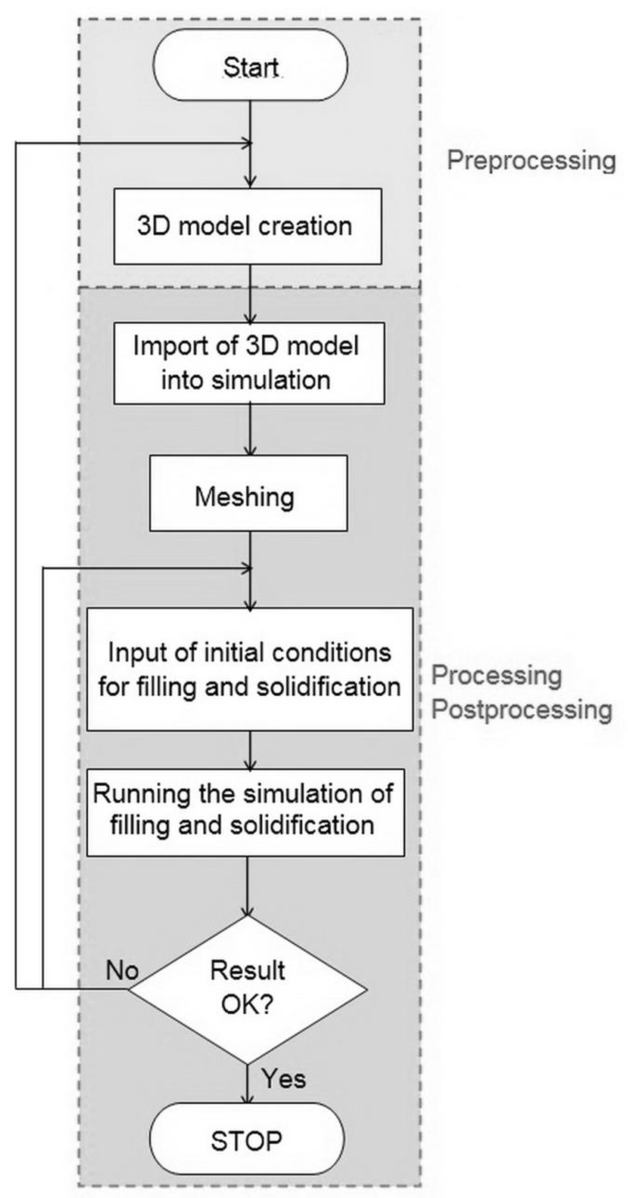
Figure 6.
Detail of mesh.
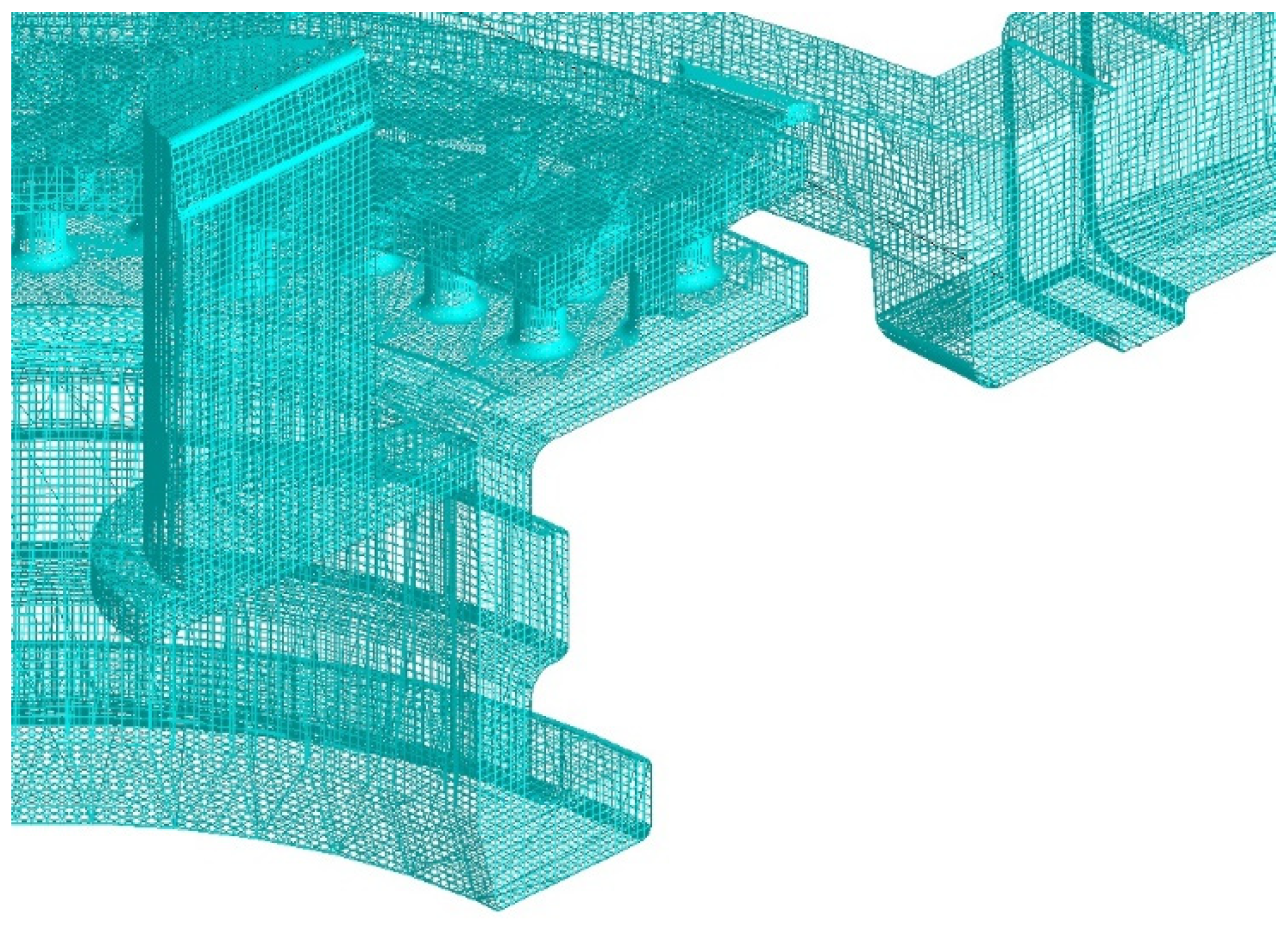
Figure 7.
Filling speed.
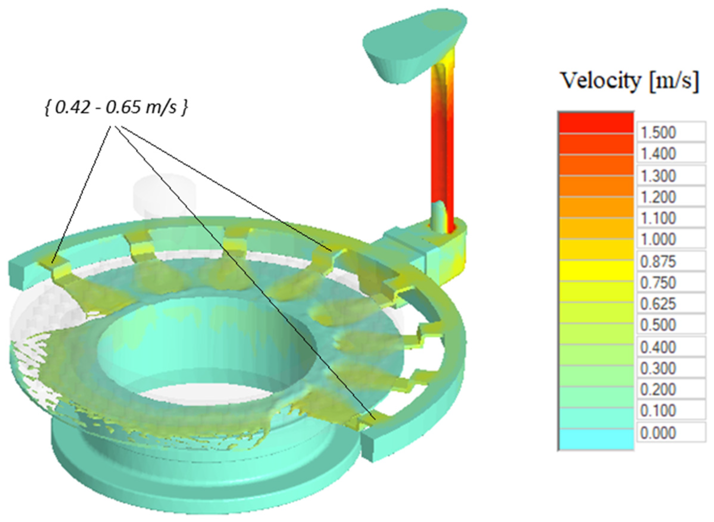
Figure 8.
Prediction of shrinkages in cast.
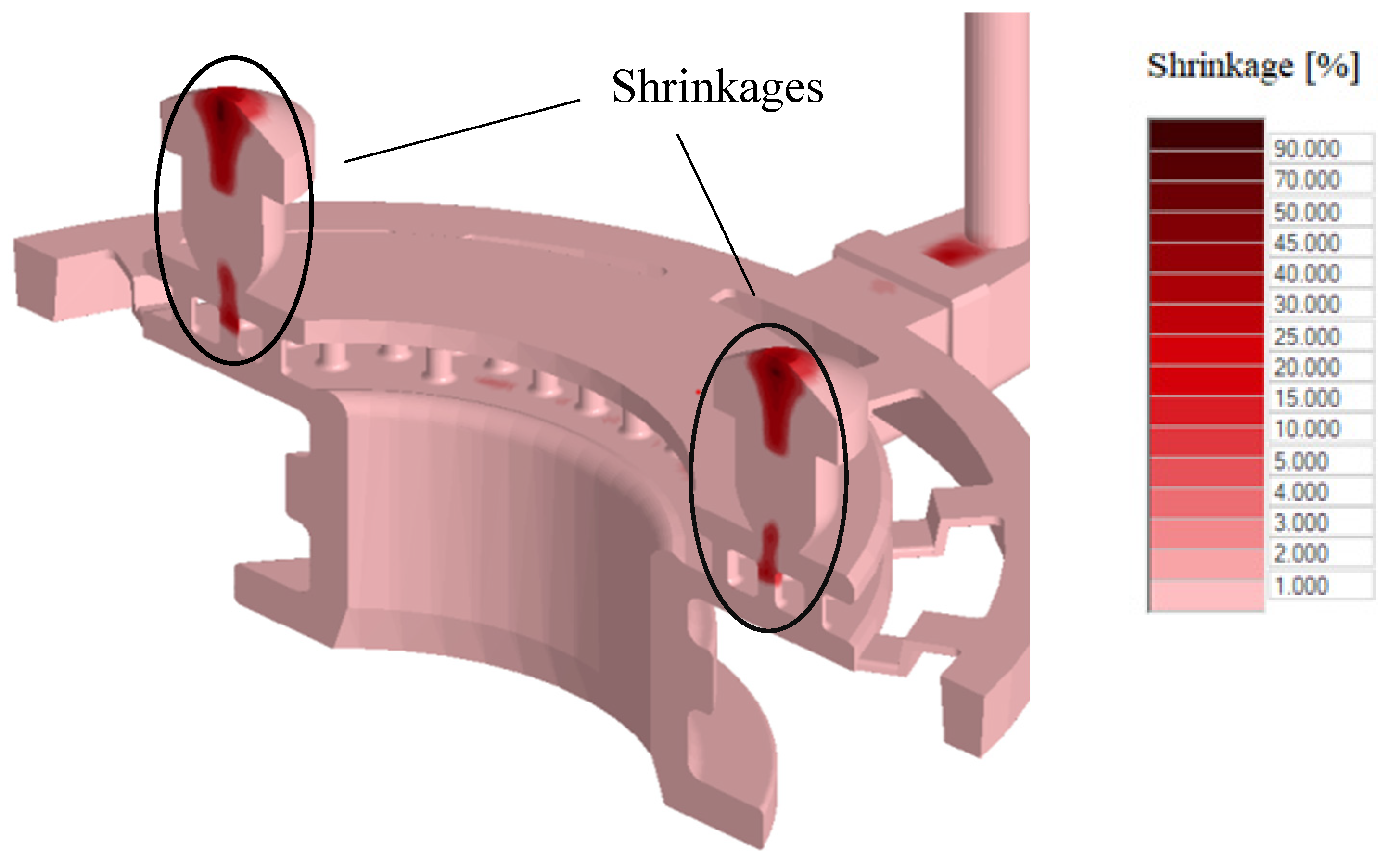
Figure 9.
Detail of shrinkages in cast.
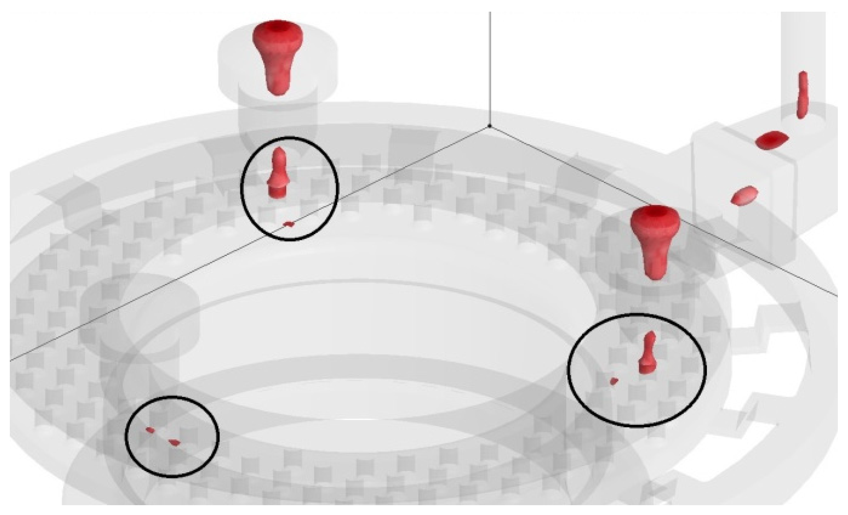
Figure 10.
New assembly with six feeders.
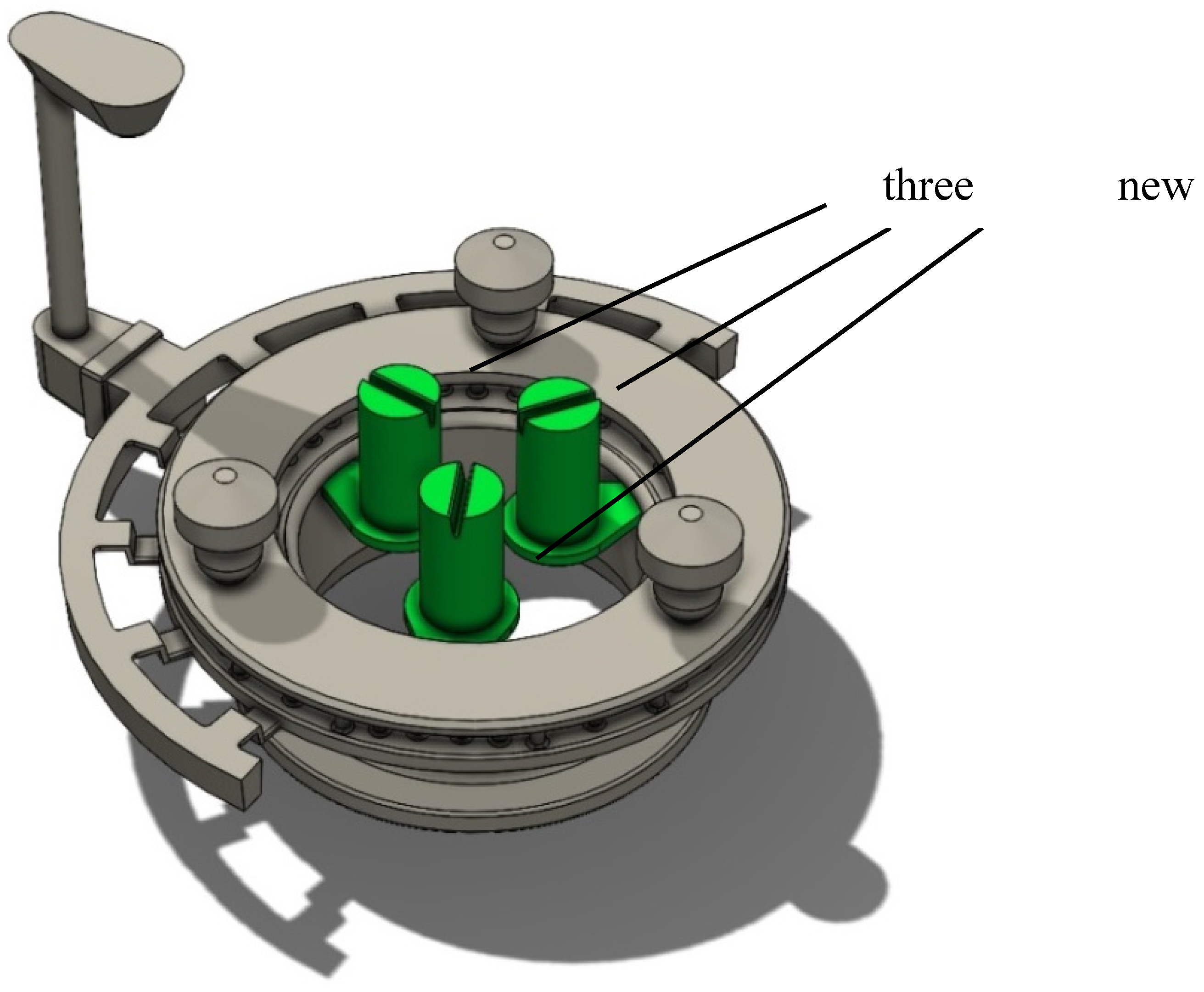
Figure 11.
Filling speed in new asssebly with six feeders.
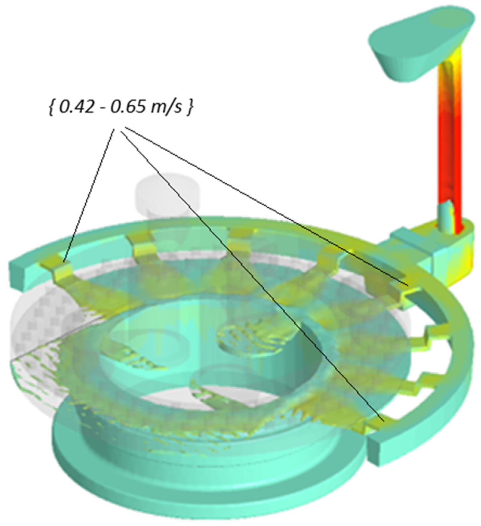
Figure 12.
Occurrence of shrinkages in the new assembly.
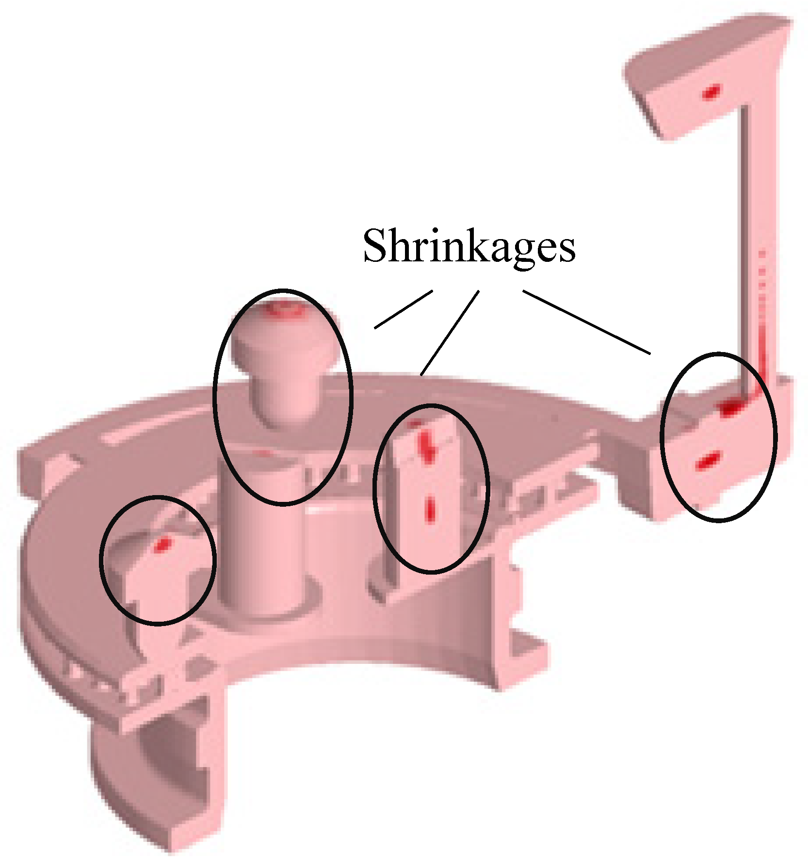
Figure 13.
A detail of the shrinkages occurring in the feeders.
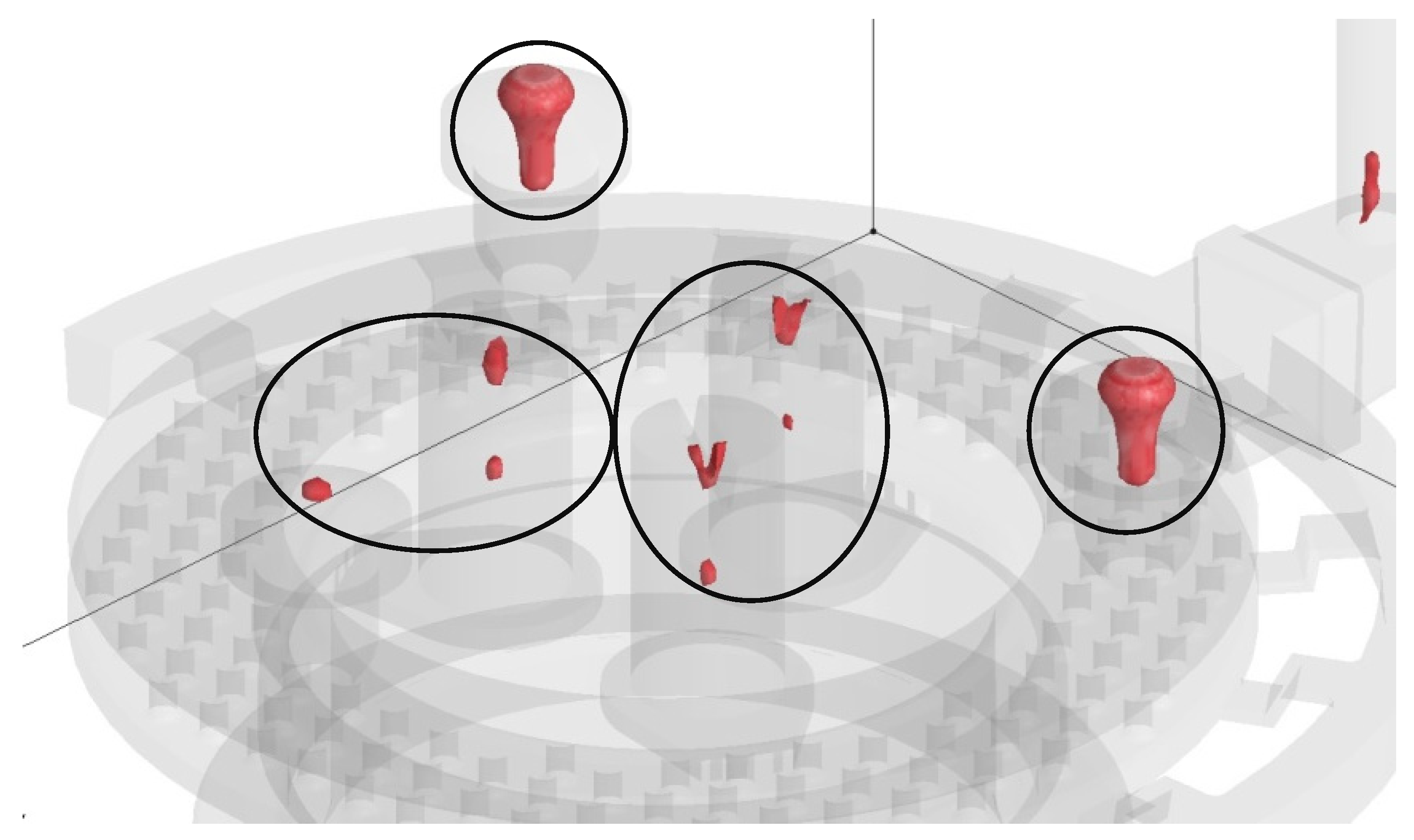
Figure 14.
Cut of the casting in the critical area (without shrinkages).
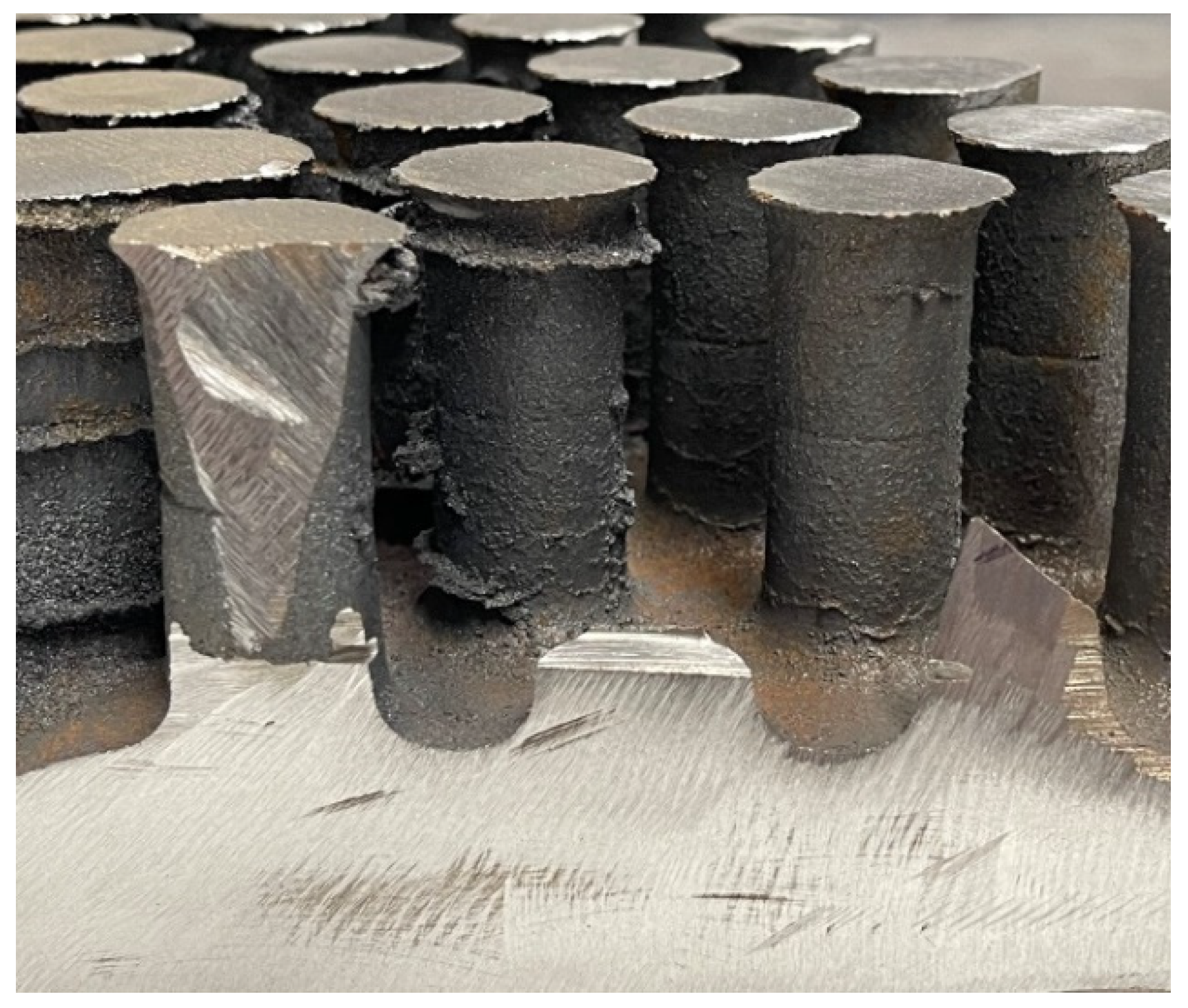
Figure 15.
Ferritic microstructural under the feeder, 100 x, etched Nital 2%.
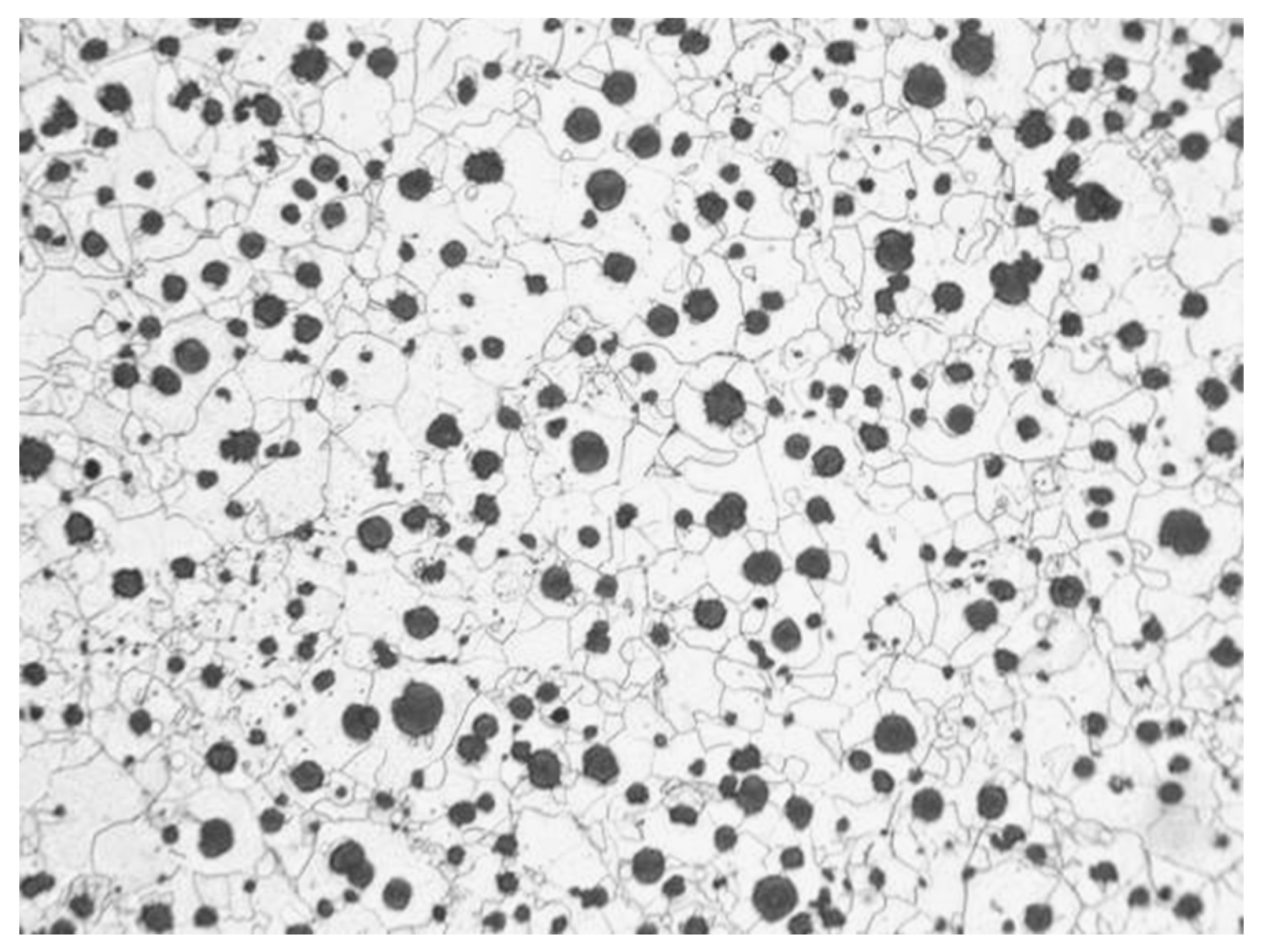

Table 1.
Input data for the computer simulation
| cast technology | gravity casting |
| alloy | EN-GJS-400-15 |
| flow rate at the inlet | 11 kg/s |
| cast temperature | 1382°C |
|
cell size coefficient of flow losses material of mold temperature of mold |
2.5 mm 0.42 Bentonite 23°C |
| number of cells | 5 900 000 |
Table 2.
The properties of the cast material from the simulation program.
| denstity at 1170 °C dyn. viscosity at 1300°C |
6800 kg/m3 0.03*10-5.m2/s |
| thermal conductivity λ at 300 °C | 36.2 W/K.m |
| thermal expansion coefficient α up to 400 °C: specific heat at 1175°C heat conduction at 1176°C |
12.5*10-6/K 900 J/Kg/°C 200 W/m/°C |
Disclaimer/Publisher’s Note: The statements, opinions and data contained in all publications are solely those of the individual author(s) and contributor(s) and not of MDPI and/or the editor(s). MDPI and/or the editor(s) disclaim responsibility for any injury to people or property resulting from any ideas, methods, instructions or products referred to in the content. |
© 2024 by the authors. Licensee MDPI, Basel, Switzerland. This article is an open access article distributed under the terms and conditions of the Creative Commons Attribution (CC BY) license (https://creativecommons.org/licenses/by/4.0/).
Copyright: This open access article is published under a Creative Commons CC BY 4.0 license, which permit the free download, distribution, and reuse, provided that the author and preprint are cited in any reuse.


