
Submitted:
19 January 2024
Posted:
19 January 2024
You are already at the latest version
Abstract
In this study, nano-diamond (ND) and MoS2 powder are used as additives in a carbonyl iron based magnetorheological fluid (MRF) to improve its tribological performance. MRFs are prepared by dispersing 35 wt.% of CI particles in silicone oil, and adding different proportions (0, 1, 3 or 5 wt.%) of ND and MoS2 additives. Seven kinds of MRFs are made and tested using reciprocating friction and wear tester under different normal loads, and then the friction characteristics are evaluated through analyzing experiment results. The morphology properties of MRFs and contacting surfaces before and after tests are also observed using a scanning electron microscope and analyzed by energy-dispersive X-ray spectroscopy. The results show that the appropriate weight percentage of MoS2 additives may decrease friction coefficient and wear zone. It is also demonstrated from the detailed analyses of worn surfaces that the wear mechanism is influenced not only by additives but also by applied normal load and magnetic field strength.
Keywords:
magnetorheological fluid (MRF)
; tribology performance
; additives
; friction
; wear surface
1. Introduction
As well known that magnetorheological fluid (MRF) is a kind of smart suspension which is in a free-flowing liquid state in the absence of a magnetic field, but under the magnetic field its apparent viscosity can be increased by more than two orders of magnitude within milliseconds and it exhibits solid-like characteristics exhibiting the field-dependent yield stress [1,2]. MRF normally has three main constituents: magnetic nonlinear particles, nonmagnetic base liquids, and stabilizer additives. Micron-sized magnetizable particles, which play a key role in MR effect, are suspended in the base liquid or oil, and stabilizer additives are utilized to overcome sedimentation problem [3]. Since the discovery of salient properties of MRF, various material components have been proposed and developed to improve MR effect. Shah et al. [4] studied the influence of large size magnetic particles on the magneto-viscous properties of MRFs through comparing the rheological properties of three different types of MRFs in the presence of the magnetic field. The results showed that the addition of large sized magnetic particles in magnetic fluid could increase the yield stress and the fluid stability under the field. Min et al. [5] examined the magnetic properties, material characteristics and sedimentation properties of two different MRFs by dispersing both carbonyl iron (CI)/polyaniline and CI micro-spheres in silicone oil and the effect of surface treatment on magnetic micro-spheres were discussed. Hato et al. [6] investigated the characterization of MRFs containing three different loading of submicron-sized organoclay particles added in CI suspension. And the dispersion stability of pure CI was improved with increasing the content of organoclay in the CI suspension. Han et al. [7] evaluated the effect of the MR particle corrosion on the performance of MRF and found that the shear stress controllability of the corroded MRFs was worse than that of original fluid. Dong et al. [8] studied the effect of CoFe2O4 additives on the material performance and dispersion stability of CI based MRFs under external magnetic field. The results showed that CoFe2O4 additives improved the MR effect of the MRF such as shear stress, shear viscosity and dynamic modulus.
Due to many saliant properties of MRFs such as controllable yield stress and fast response time, numerous application systems were proposed and studied so far in the field of automotive industry, mechanical engineering, aerospace, construction, and health care [9]. However, before the application of MRFs, a study on the durability and mechanical properties needs to be sufficiently investigated. Recently, the effect of friction and wear is recognized as a crucial factor that must be considered. Wong et al. [10] investigated the tribological behavior of an MRF without the magnetic field activation using a block on ring tester. Seok et al. [11] examined the tribological properties of an MRF in a finishing process and the results showed that the dominant wear mechanism in the finishing process was abrasion. In addition, a semi-empirical material removal model was proposed in this work for the description of the tribological behavior of the MRF. Song et al. [12] studied the effect of magnetic field on the friction and wear performance of MRF under different load and rotating speed using pin-on-disc wear apparatus. Song et al. [13] proposed a simplified experiment with a disc-on-friction apparatus to investigate the frictional behavior of counter-faces lubricated by MRF under the magnetic field. Wang et al. [14] investigated the effect of surface texture of specimens on the braking performance of MR brake under different working conditions. On the other hands, several works on the tribological properties of MRFs have been carried out. Hu et al. [15] investigated the friction and wear properties of CI based MRFs which added different constituent additives. It was found that MRFs showed controlled tribological properties under different magnetic field. Reeves et al. [16] experimentally demonstrated that an appropriate size boron nitride particle could enhance the lubricity and minimize wear in the tribo-interface.
Up to now, many materials such as grease, iron naphthenate, lithium stearate, oleic acid, naphthenate, sulfonate, glycerol monooleate, silica and so on, have been used as additives which can improve MRF properties such as the field-dependent yield stress and sedimentation of particles and interparticle friction, in addition to improve the mechanical properties of MRFs [3,17]. In recent decades, nano-diamond (ND) has been widely used in the field of lubricants, greases and coolants of machinery, metal processing, engine manufacturing, shipbuilding, aviation, transportation, and so on [18,19]. In general, ND additives added in oils or lubricants could improve the working life of tool and reduce boundary friction and wear. For example, the friction coefficient was reduced to 20~30%; friction torque was reduced by 20~40%; wear surfaces were reduced to 30~40% during the machining process [20]. However, as far as the authors know, there is no report on the friction and lubrication characteristics of MRFs with ND additives. Consequently, the main technical contribution of this work is to experimentally investigate the tribological performance of CI-based MRFs with the additives of ND and MoS2 powder. To achieve the research goal, as a first step, seven types of MRFs are fabricated and investigated experimentally under different loading and magnetic field using a reciprocating friction and wear tester. Subsequently, the effect of the additive constituents and additive concentrations of MRFs on the friction and wear properties are observed. In addition, the surfaces of specimens are examined by surface profilometer, optical microscope and scanning electron microscope (SEM) coupled with energy dispersive X-ray spectroscopy (EDS) to investigate the field-dependent morphological characteristics.
2. Experimental Procedures
In this study, soft magnetic CI particles, silicone oil and different proportion of ND and MoS2 powder were used as a dispersed phase, suspending medium and additives for MRFs, respectively. The CI MRF was prepared by dispersing 35 wt.% CI particles in the silicone oil, the CI/ND MRFs were prepared by adding1, 3 or 5 wt.% ND to the CI MRF, and the CI/ MoS2 MRFs were prepared by adding1, 3 or 5 wt.% MoS2 to the CI MRF. The mixtures were treated by vibration dispersive mixing to ensure a uniform distribution of CI particles in the solution. Some methods were employed in the process such as ultrasonic dispersion, high-speed dispersion and mechanical milling [3].
The friction tests were performed using a reciprocating friction and wear tester which schematic diagram of the experimental device is shown in Figure 1. In this device, a fixing system was used to fix pin and disc samples by an upper holder and lower holder on the testing machine. The MRFs were applied on the disc surface. A direct current motor control system was used to provide accurate speed control to drive the pin samples with a periodic reciprocating motion on the disc samples using a crankshaft connecting rod system with a reciprocating stroke of 10 mm. A normal loading system was used to put external load, and the load cell was used to measure the friction force (F). And the friction coefficient was calculated by the following equation:
where, mk is kinetic friction coefficient, F is nominal, measured friction force during sliding, and P is applied load (normal force). Electro-magnet which was installed under the disc could provide a sufficient magnetic field strength to the MRF. And the magnetic induction produced by an electromagnet was measured using a Tesla meter. It could be found that the magnetic field strength of up to 25 mT could be applied to the surface of the samples. In this study, the magnetic field strength of 10mT was applied. A computer control system was used to collect and process the experimental data from the transducers. The samples for reciprocating friction tests are aluminum. The diameter and length of the pin samples are 10 mm and 25 mm, the diameter and thickness of the disc samples are 60 mm and 8mm, respectively. The disc samples were processed as thin as possible under the premise of not to undermine the material mechanics performance. In order to reduce the effects of surface roughness on the experimental results as much as possible, the surface treatment of pin and disc samples were carried out. In this study, all the tests were run under the same ambient conditions and normally for the same duration of 1800 cycles. In order to understand the impact of variation of friction coefficient, the oscillation frequency of 1 Hz and the load conditions was set to 5, 10 and 15 N. During tests, the friction coefficient on the contact surface were measured and recorded directly through experimental apparatus. The pin and disc samples were cleaned by an ultrasonic cleaner before and after tests. The surfaces of the samples were examined by surface profilometer and optical microscope. The CI particles were observed by SEM, and the chemical composition of the prepared MRF was analyzed using EDX.
3. Results and Discussion
3.1. Effect of Load and Magnetic Field
CI based MRF added 3 wt.% ND additives was tested under the loads of 5, 10 and 15 N, and the experimental results were shown in Figure 2, Figure 3 and Figure 4. The friction coefficient changes along the cycle times with and without magnetic field were shown in Figure 2. It shows that the curves mainly increase with test cycles slightly. However, under the loads of 10 and 15N, the curves increase rapidly along the first 500 cycles. The friction coefficient has a little upward trend along cycle times. And the friction coefficient increases with the load condition decreasing. The results also show that the friction coefficient under a magnetic field has higher values than one without a magnetic field, but the tendency is similar in both cases. Aluminum has lower hardness among other metal materials. When the magnetic field was applied, the magnetic-particle chains formed on the surface of disc thereby to influence the properties of friction and wear. It is noted here that all experiments were repeated more than three times under the same conditions.
In order to further observe the surface morphology and wear changes, an optical microscope was used to evaluate the general morphology of the disc samples. Figure 3 show optical microscopy images of the general morphology of the worn zone of the disc samples after tests under different load and magnetic field conditions. Figure 3a,c,e shows the abrasive position of the disc samples without magnetic field, and the Figure 3b,d,f show the abrasive position of the disc with the magnetic field strength of 10mT. The wear zone width and abrasion also be seen on the disc surface after tests. When magnetic field strength of 10mT added, the wear zone width was obviously increased. But the tendency of wear zone was different with and without magnetic field.
Figure 4 shows the profile of the disc surface with CI based MRF added 3 wt.% ND additives under different load and magnetic field conditions. The results show that the profile of the surface without magnetic field has the lowest worn profile among all cases and the magnetic field strength of 10mT resulted in the largest worn profile. The width and depth of worn profile increased with increasing load conditions. During test, majority of magneto-rheological particles were trapped within the contact zone by the action of magnetic forces when a magnetic field was applied [21]. Due to the distribution of contact pressure between the pin and disc, the center position of pin took the maximum contact pressure, it made the most wear occurred around 500mm in X-axis for all of the test cases when MR particles participate in the wear process.
3.2. Effect of Additive Constituents and Contents
Seven types of CI based MRFs with 0, 1, 3 and 5 wt.% contents of ND and MoS2 additives were fabricated to investigate the effect of additives constituents and contents on friction and wear properties of MRFs. The samples were tested under the load of 10 N with magnetic field strength of 0 and 10 mT, and the results were shown in Figure 5, Figure 6, Figure 7, Figure 8, Figure 9 and Figure 10. Friction coefficient of MRFs added different contents of ND additives along cycle times are displayed in Figure 5. It shows that the variation of friction coefficient increases with increasing ND additives contents, and the MRF without additives has the fewest change of friction coefficient along cycle time. Moreover, the friction coefficient increased when the magnetic field strength increased from 0 to 10 mT, but not increases with increasing ND additives contents. The curves show that the friction coefficient of MRF with 1 wt.% ND additives contents is a little higher than 5 wt.% and much higher than 3 wt.%.
Figure 6 shows the friction coefficient of MRFs added different content of MoS2 additives with different magnetic field strength. It shows that the friction coefficient not only increases with increasing MoS2 additives contents, but also all lower than the one without additives. And the MRF added 1 wt.% MoS2 additives has the lowest friction coefficient. It also could be found that the effect of magnetic field strength on friction coefficient of MRFs added MoS2 additives is not obvious. Whether the magnetic field is applied or not, the MRFs added MoS2 additives have a low friction coefficient than that added ND additives. And the stability of the MRFs added MoS2 additives is better than the one added ND additives. On the other hand, friction coefficient of the base oil with ND particles presented irregular variation with temperature [22,23].
Optical micrographs of the worn surfaces of disc samples after the tests are shown in Figure 7 and Figure 8. It can be observed that the worn areas on the disc surfaces not only increased with increasing contents of ND additives but also increased with applied magnetic field strength. For the MRFs added ND additives, additives have more obvious effect. But for the MRFs added MoS2 additives, magnetic field strength has more obvious effect. The density and viscosity of additives in MRF is increased with the additive contents increasing. The hardness and particle size of ND is bigger than CI particles of MRF led to the wear and tear aggravate. When the magnetic field applied, the CI particles are arranged in a chain structure lead to wear area increase. Comparing Figure 7 with Figure 8, it could be found that the width of wear area with MoS2 additives is smaller than the MRFs added ND additives. In addition, in order to compare the surface roughness of the disc with different additives contents after the experiment, a surface profilometer (Mitsutoyo SurfTest SV-3100) was used to measure the arithmetical mean wear surface profiles of the discs. The measurement data were obtained at different load and different additives contents, and the wear surface profiles are shown in Figure 9 and Figure 10. These figures show that wear surface profiles increase with the increasing of ND and MoS2 additives contents. And there has the best roughness at the additive contents of 1 wt.% in all test data. It is also revealed that for the MRFs with different content additives, the depth of wear area increases with additives contents. And the depth of wear areas of MRFs added MoS2 additives are smaller than the MRFs added ND additives. However, in Figure 10, the depth of wear area of the MRF with 1 wt.% MoS2 additives is smaller than the MRF without additives under 0 and 10 mT magnetic field strength.
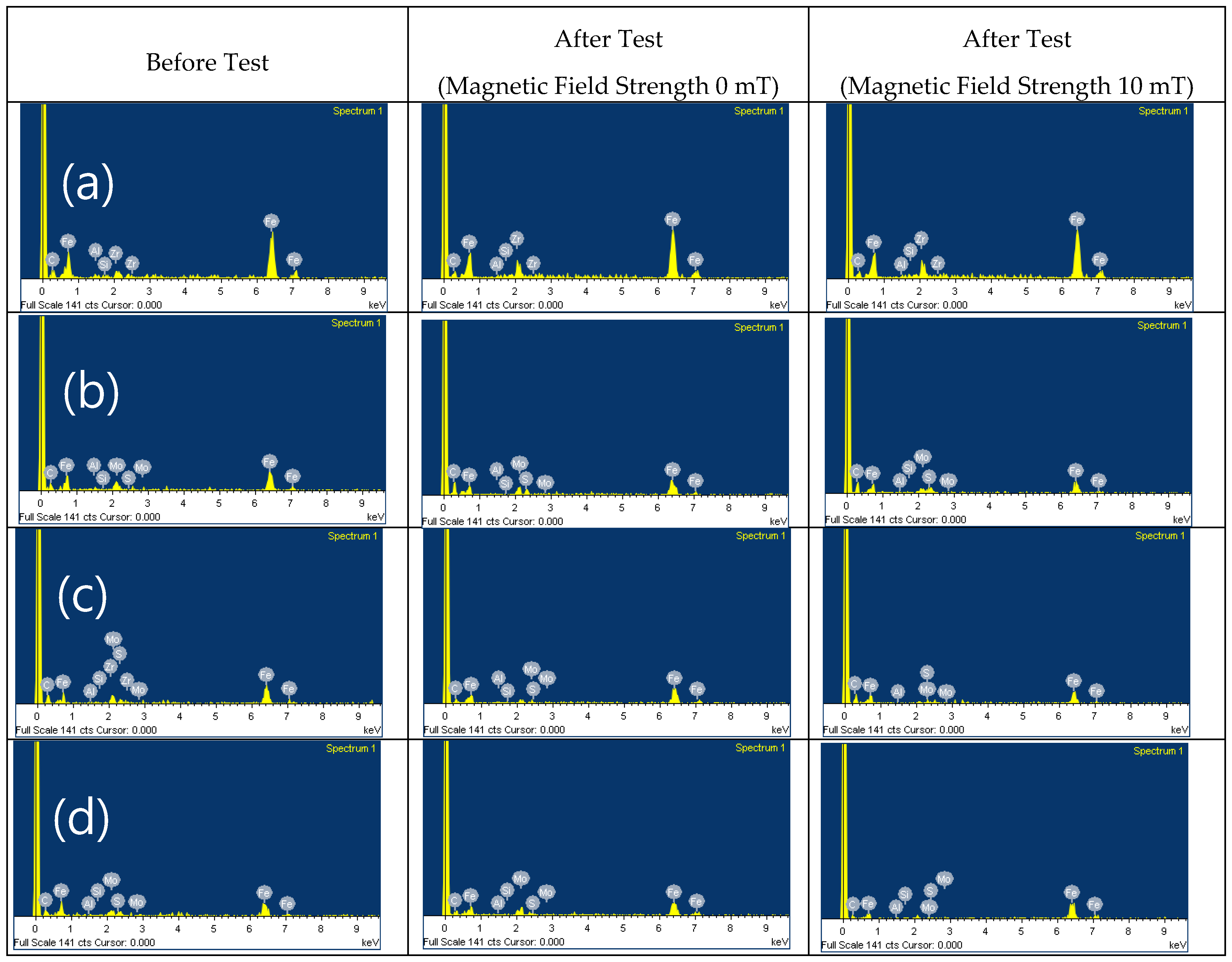
The SEM images and EDX results of the MRFs with ND or MoS2 additives before and after tests are shown in Figure 11, Figure 12, Figure 13 and Figure 14. The particle size and the contents of ND, MoS2 additives and MRF can be confirmed through these SEM images. Comparing the SEM images, it could be confirmed that the size of CI particles was changed to be smaller after test. And it is more obvious when the ND and MoS2 is added in MRFs. The EDX spectra of the disc surface with MRFs added ND and MoS2 additives before and after test, respectively. The changes of chemical composition of the disc surface with MRFs added ND additives with and without magnetic field after the test is given in Figure 13. It can be seen that after tests the contents of the elements C and Zr is increased. Because of the influence of the magnetic field increases the wear and tear, so the contents of Fe and C elements increased more than magnetic field is unapplied after the test. Figure 14 shows the chemical composition of the disc surface with MR fluids added MoS2 additives before and after the test. The chemical composition data show that the C and Fe contents are reduced, and the Mo, S and Fe contents increased. Overall, the involvement of iron particles and other components from the MRF led to the change in chemical composition of the plate surface after the test, thus causing Al content to increase on the coating surface after the friction wear test.
4. Conclusions
In this study, the friction and wear characteristics of CI-based MRFs with ND and MoS2 additives (1, 3 and 5 wt.%) were investigated under the load of 5, 10 and 15N, 1800 cycles, respectively. The results show that the coefficient of friction increases with the load condition decreases. The width and depth of wear area are increased with weight percentage of ND and MoS2 additives is increasing. Comparing with the MRF without additives, the width and depth of wear area are decreased when 1 wt.% MoS2 additives added to MRF. The density and viscosity of additives in the MRFs are also increased with the additives weight percentage increasing which may lead to the increment of the width and depth of the wear. When the magnetic field is applied, the friction coefficient of MRFs is decreased. On the contrary, the wear zone width and depth are increased when the magnetic field is applied. The width and depth of wear area with MoS2 additives is smaller than ND additives. In addition to the contents of Fe and C elements, the contents of Zr and Mo, S elements are also increased after the tests when ND and MoS2 additives are added in MRFs. It has been shown from this work that the friction characteristics of MRFs can be improved through addition of appropriate additives resulting in the positive lubrication performance of many practical application systems of MRFs.
Author Contributions
Conceptualization, S.R.Z., W.L.S., P.Z. and S.-B.C.; methodology, W.L.S., P.Z. and S.-B.C.; validation, W.L.S. and S.-B.C.; formal analysis, S.R.Z., Y.B.C, W.L.S. and S.-B.C.; investigation, W.L.S. and P.Z.; resources, W.L.S., P.Z. and S.-B.C.; data curation, S.R.Z., Y.B.C, W.L.S. and P.Z.; writing—original draft preparation, S.R.Z., Y.B.C, and W.L.S.; writing—review and editing, W.L.S., Y.B.C, and S.-B.C.; visualization, S.R.Z. and W.L.S.; supervision, W.L.S.; project administration, W.L.S.
Conflicts of Interest
The authors declare no conflict of interest.
Abbreviations
| ND | Nano-diamond |
| CI | Carbonyl iron |
| MRF | Magnetorheological fluid |
| SEM | Scanning electron microscope |
| EDX | Energy-dispersive X-ray spectroscopy |
References
- Ashour, O.; Rogers, C.A.; Kordonsky, W. Magnetorheological Fluids: Materials, Characterization, and Devixces. J.Intel.Mat.Syst.Str. 1996, 7, 123–130. [Google Scholar] [CrossRef]
- Wang, X.J.; Gordaninejad, F. Flow Analysis of Field-Controllable, Electro- and Magneto-Rheological Fluids Using Herschel-Bulkley Model. J. Intel. Mat. Syst. Str. 1999, 10, 601–608. [Google Scholar] [CrossRef]
- Ashtiani, M.; Hashemabadi, S.H.; Ghaffari, A. A Review on the Magnetorheological Fluid Preparation and Stabilization. J. Magn. Magn. Mater. 2015, 374, 716–730. [Google Scholar] [CrossRef]
- Shah, K.; Upadhyay, R.V.; Aswal, V.K. Study of the Magnetorheology of Bimodal Magnetite Suspension. Smart. Mater. Struct. 2012, 1447, 1209–1210. [Google Scholar]
- Min, T.H.; Choi, H.J.; Kim, N.H.; Park, K.J.; You, C.Y. Effects of surface treatment on magnetic carbonyl iron/polyaniline microspheres and their magnetorheological study. Coll. Surf. A. 2017, 48–55. [Google Scholar] [CrossRef]
- Hato, M.J.; Choi, H.J.; Sim, H.H.; Park, B.O.; Ray, S.S. Magnetic carbonyl iron suspension with organoclay additive and its magnetorheological properties. Coll. Surf. A. 2011, 377, 103–109. [Google Scholar] [CrossRef]
- Han, Y.M.; Kim, S.; Park, Y.D.; Kang, J.W.; Choi, S.B. Field-dependent characteristics of magnetorheological fluids containing corroded iron particles. Smart. Mater. Struct. 2015, 24. [Google Scholar] [CrossRef]
- Dong, Y.Z.; Piao, S.H.; Zhang, K.; Choi, Y.J. Effect of CoFe2O4 nanoparticles on a carbonyl iron based magnetorheological suspension. Coll. Surf. A. 2018, 537, 102–108. [Google Scholar] [CrossRef]
- Bica, I.; Liu, Y.D.; Choi, H.J. Physical characteristics of magnetorheological suspensions and their applications. J. Ind. Eng. C. 2013, 19, 394–406. [Google Scholar] [CrossRef]
- Wong, P.L.; Bullough, W.A.; Feng, C.; Lingard, C. Tribological performance of a magneto-rheological suspension. Wear. 2001, 247, 33–40. [Google Scholar] [CrossRef]
- Seok, J.W.; Lee, S.O.; Jang, K.I.; Min, B.K.; Lee, S.J. Tribological Properties of a Magnetorheological (MR) Fluid in a Finishing Process. Tribol. T. 2009, 5, 460–469. [Google Scholar] [CrossRef]
- Song, W.L.; Li, C.H.; Choi, S.B. Finishing Performance of Magneto-Rheological Fluid under Magnetic Field. Trans. Nonferrous. Met. Soc. China. 2013, 23, 400–405. [Google Scholar] [CrossRef]
- Song, W.L.; Seong, M.S.; Choi, S.B.; Lee, C.H.; Cho, M.W. Tribological characteristics of magneto-rheological fluid for movement sensor application. Smart. Mater. Struct. 2014, 23, 017001. [Google Scholar] [CrossRef]
- Wang, N.; Li, D.H.; Song, W.L.; Xiu, S.C.; Meng, X.Z. Effect of surface texture and working gap on the braking performance of the magnetorheological fluid brake. Smart. Mater. Struc. 2016, 25, 105026. [Google Scholar] [CrossRef]
- Hu, Z.D.; Yan, H.; Qiu, H.Z.; Zhang, P.; Liu, Q. Friction and wear of magnetorheological fluid under magnetic field. Wear 2012, 278-279, 48–52. [Google Scholar] [CrossRef]
- Reeves, C.J.; Menezes, P.L.; Lovell, M.R.; Jen, T.C. The influence of surface roughness and particulate size on the tribological performance of bio-based multi-functional hybrid lubricants. Tribol. Int. 2015, 88, 40–55. [Google Scholar] [CrossRef]
- Zhu, Y.M.; Xu, F.; Shen, J.L.; Wang, B.C.; Xu, X.Y.; Shao, J.B. Study on the modification of nanodiamond with DN-10. J. Mater. Sci. Technol. 2007, 23, 599–603. [Google Scholar]
- Mochalin, V.N.; Shenderova, O.; Ho, D.; Gogotsi, Y. The properties and applications of nanodiamonds. Nat. Nanotechnol. 2012, 7, 11–23. [Google Scholar] [CrossRef]
- Tian, Y.X.; Liu, H.L.; Sheldon, B.W.; Webster, T.J.; Yang, S.C.; Yang, H.L.; Yang, L. Surface energy-mediated fibronectin adsorption and osteoblast responses on nanostructured diamond. J. Mater. Sci. Technol. 2019, 35, 817–823. [Google Scholar] [CrossRef]
- Dolmatov, V.N. Detonation nanodiamonds in oils and lubricants. J. Superhard. Mater. 2010, 32, 14–20. [Google Scholar] [CrossRef]
- Wang, N.; Diao, Z.Y.; Peng, Z.; Xue, X.Y.; Zhang, M.; Song, W.L. Influence of Initial Surface Roughness on Tribological Characteristics of Magnetorheological Fluid Based on Damper Design. Nanosci. Nanotechnol. Lett. 2018, 10, 633–642. [Google Scholar] [CrossRef]
- Hosseini, M.S.; Rostami, M.; Mohammadi, A. Study of Effects of Nano-diamond as an oil additive on engine oil properties and wear rate of the internal parts of agricultural tractors engines. Mech. Eng. 2013, 57, 14443–14447. [Google Scholar]
- Wang, D.M.; Zi, B.; Zeng, Y.S.; Hou, Y.F.; Meng, Q.R. Temperature-dependent material properties of the components of magnetorheological fluids. J. Mater. Sci. 2014, 49, 8459–8470. [Google Scholar] [CrossRef]
Figure 1.
Schematic diagram of the reciprocating friction and wear tester.
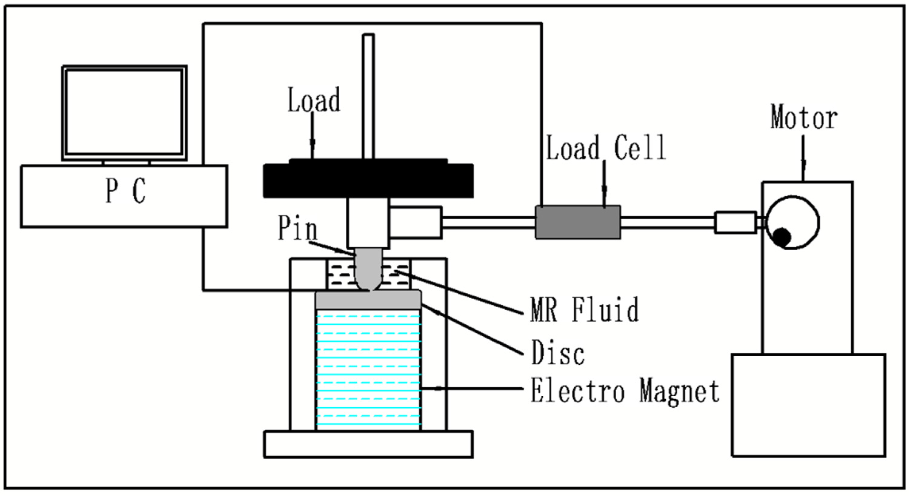
Figure 2.
Friction coefficient of MRF with 3 wt.% ND additives under different loading conditions.
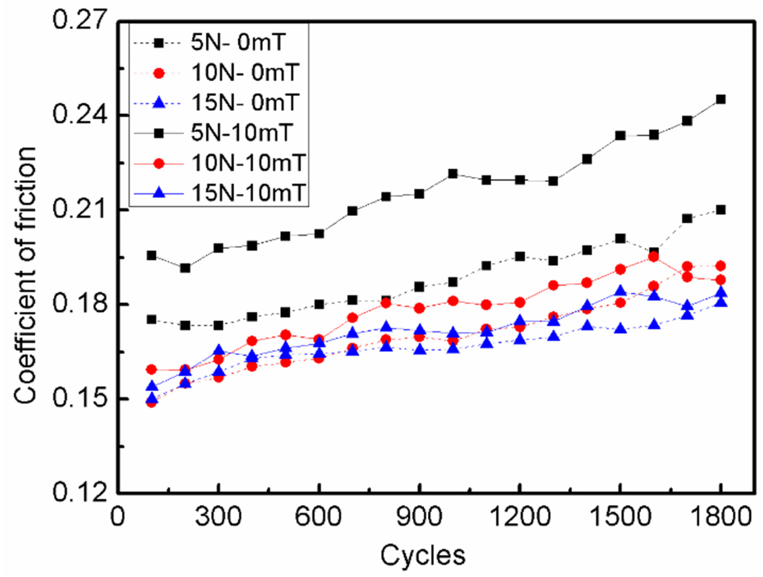
Figure 3.
Optical microscope micrographs of disc samples after the tests with MRF added 3 wt.% ND additives under different load conditions: (a) and (b) are 5N; (c) and (d) are 10N; (e) and (f) are 15N.
Figure 3.
Optical microscope micrographs of disc samples after the tests with MRF added 3 wt.% ND additives under different load conditions: (a) and (b) are 5N; (c) and (d) are 10N; (e) and (f) are 15N.
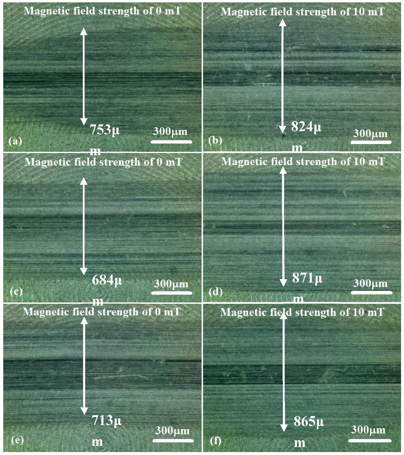
Figure 4.
Wear surface profiles of disc samples with different load conditions: (a) magnetic field strength of 0 mT; (b) magnetic field strength of 10 mT.
Figure 4.
Wear surface profiles of disc samples with different load conditions: (a) magnetic field strength of 0 mT; (b) magnetic field strength of 10 mT.
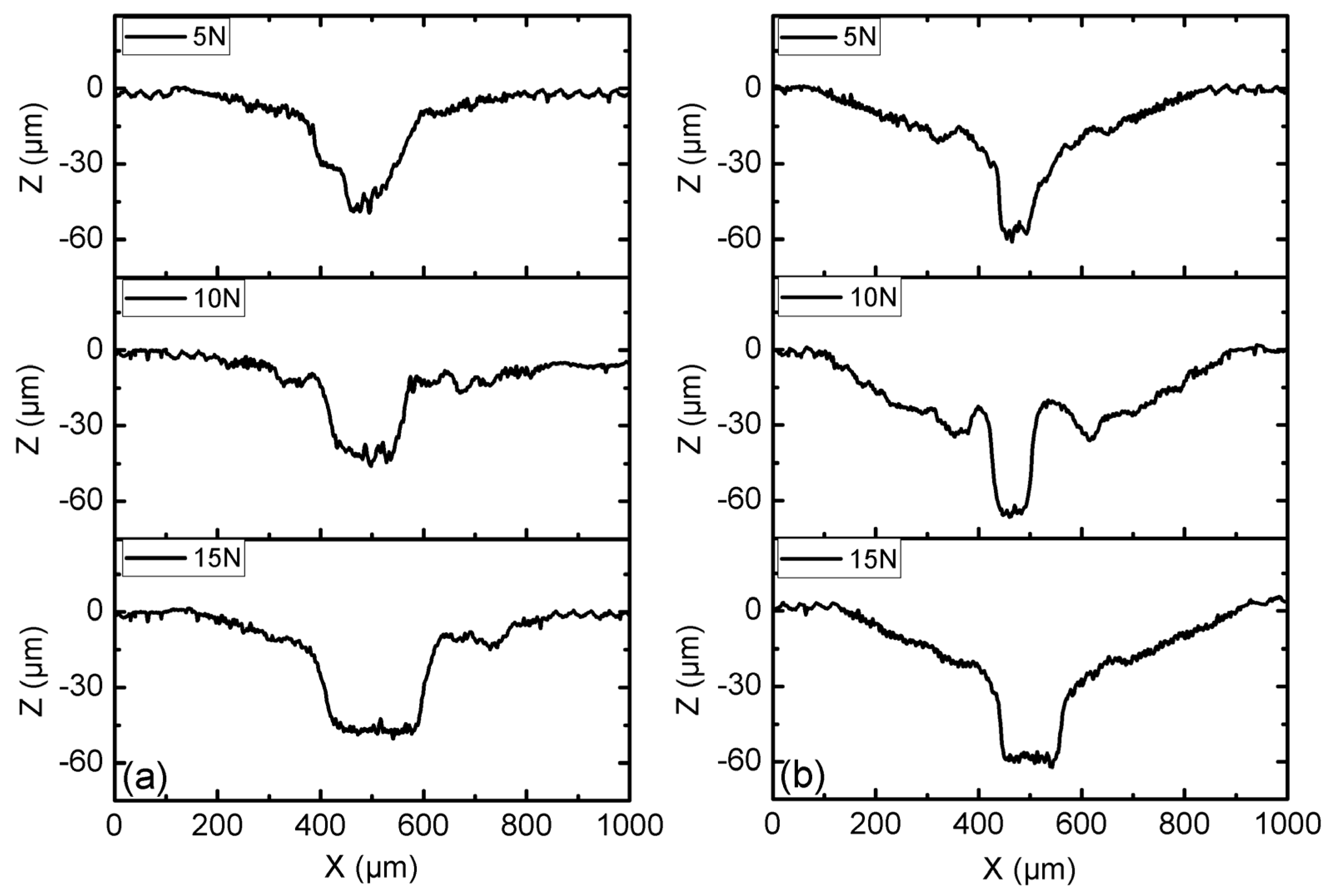
Figure 5.
Change in the coefficient of friction with different ND additives content: (a) magnetic field strength of 0 mT; (b) magnetic field strength of 10 mT.
Figure 5.
Change in the coefficient of friction with different ND additives content: (a) magnetic field strength of 0 mT; (b) magnetic field strength of 10 mT.
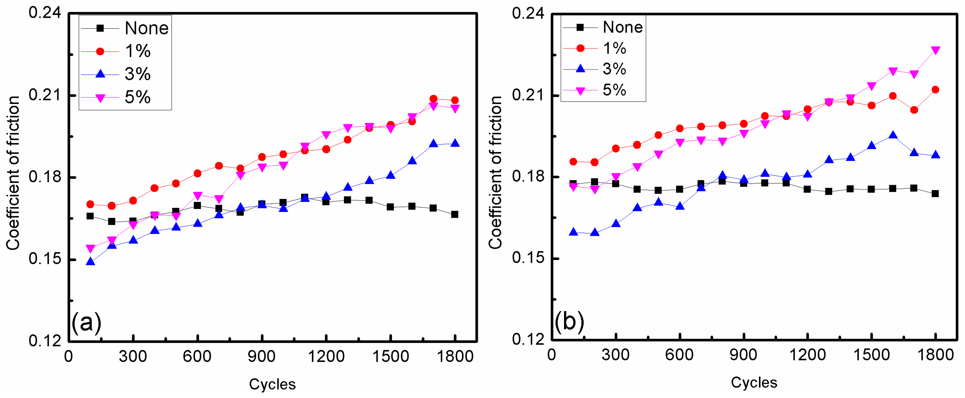
Figure 6.
Change in the coefficient of friction with different MoS2 additives content: (a) magnetic field strength of 0 mT; (b) magnetic field strength of 10 mT.
Figure 6.
Change in the coefficient of friction with different MoS2 additives content: (a) magnetic field strength of 0 mT; (b) magnetic field strength of 10 mT.
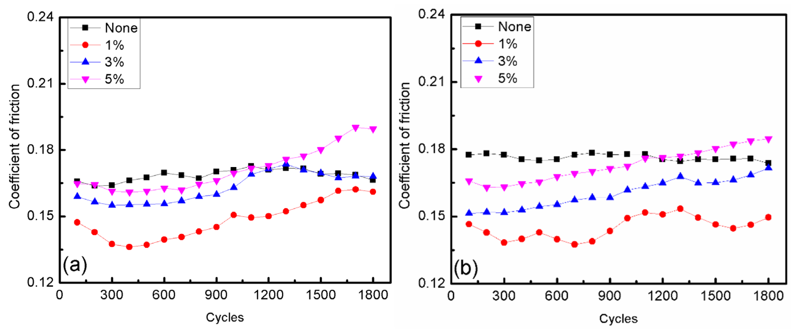
Figure 7.
Optical microscope micrographs of discs after the tests with MRFs added different content ND additives: (a) and (b) are 0%, (c) and (d) are 1 wt.%, (e) and (f) are 3 wt.%, (g) and (h) are 5 wt.%.
Figure 7.
Optical microscope micrographs of discs after the tests with MRFs added different content ND additives: (a) and (b) are 0%, (c) and (d) are 1 wt.%, (e) and (f) are 3 wt.%, (g) and (h) are 5 wt.%.
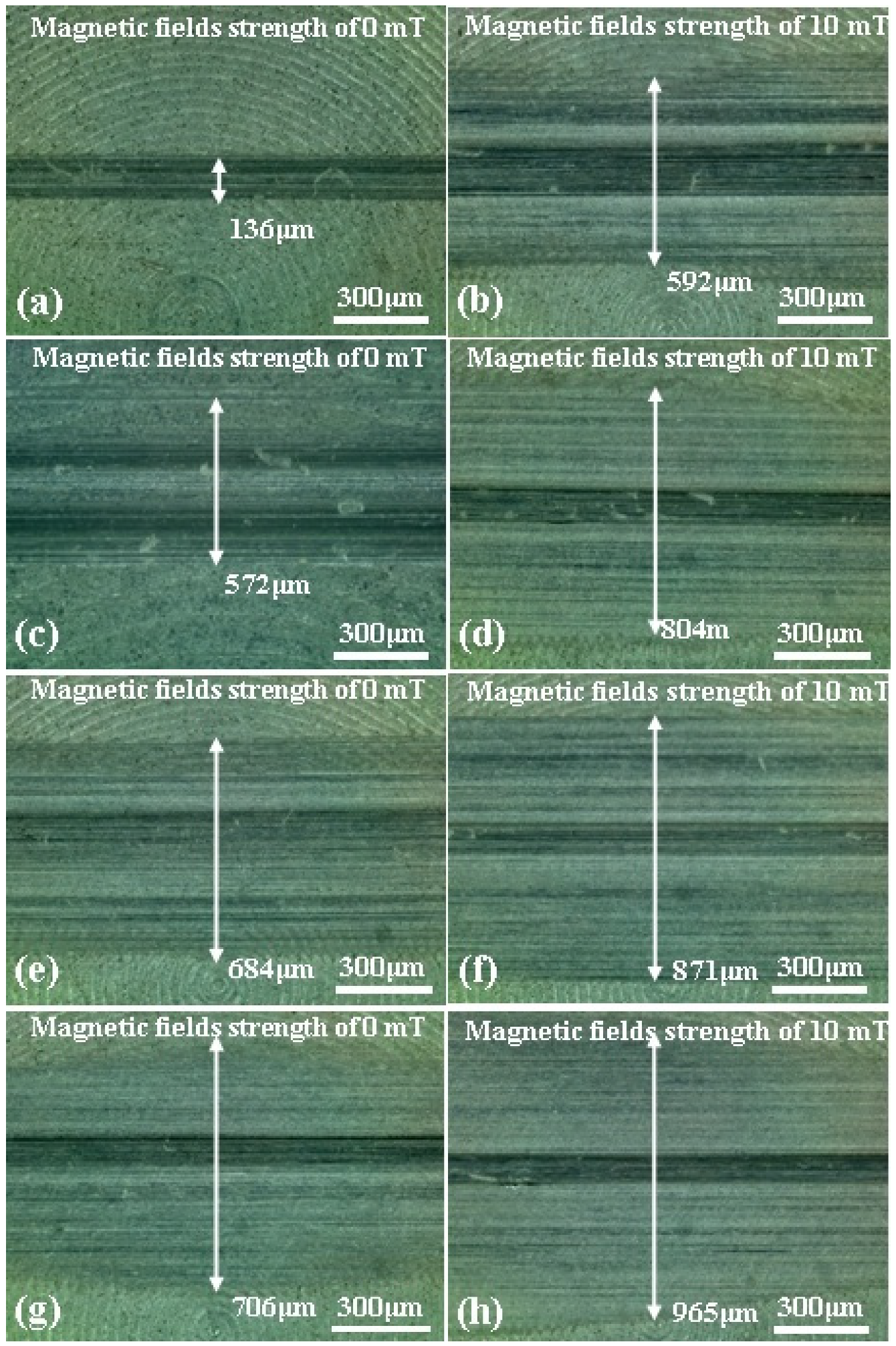
Figure 8.
Optical microscope micrographs of discs after the tests with MRFs added different content MoS2 additives: (a) and (b) are 0%, (c) and (d) are 1 wt.%, (e) and (f) are 3 wt.%, (g) and (h) are 5 wt.%.
Figure 8.
Optical microscope micrographs of discs after the tests with MRFs added different content MoS2 additives: (a) and (b) are 0%, (c) and (d) are 1 wt.%, (e) and (f) are 3 wt.%, (g) and (h) are 5 wt.%.
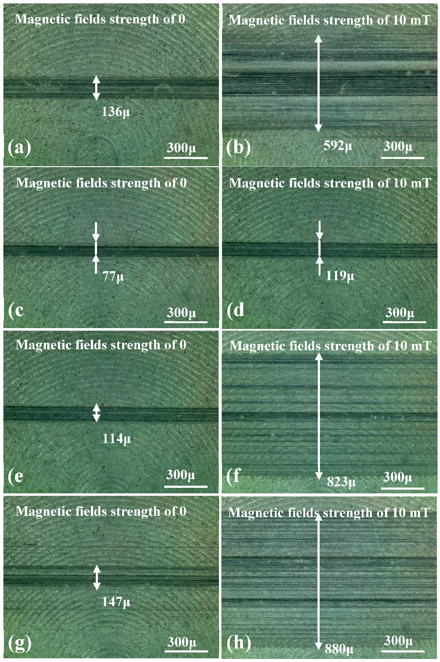
Figure 9.
Wear surface profiles of discs with different ND additives content: (a) magnetic field strength of 0 mT; (b) magnetic field strength of 10 mT.
Figure 9.
Wear surface profiles of discs with different ND additives content: (a) magnetic field strength of 0 mT; (b) magnetic field strength of 10 mT.
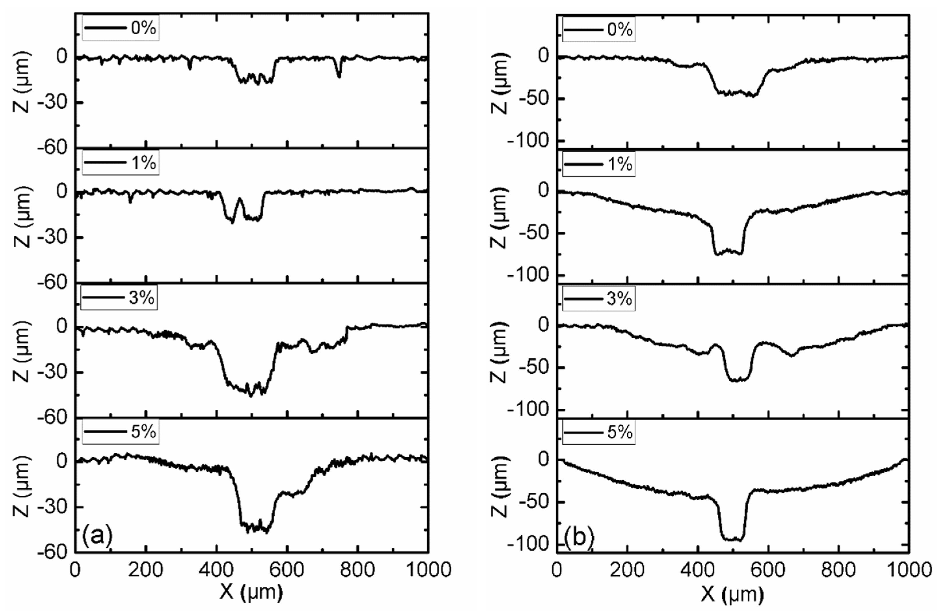
Figure 10.
Wear surface profiles of discs with different MoS2 additives content: (a) magnetic field strength of 0 mT; (b) magnetic field strength of 10 mT.
Figure 10.
Wear surface profiles of discs with different MoS2 additives content: (a) magnetic field strength of 0 mT; (b) magnetic field strength of 10 mT.
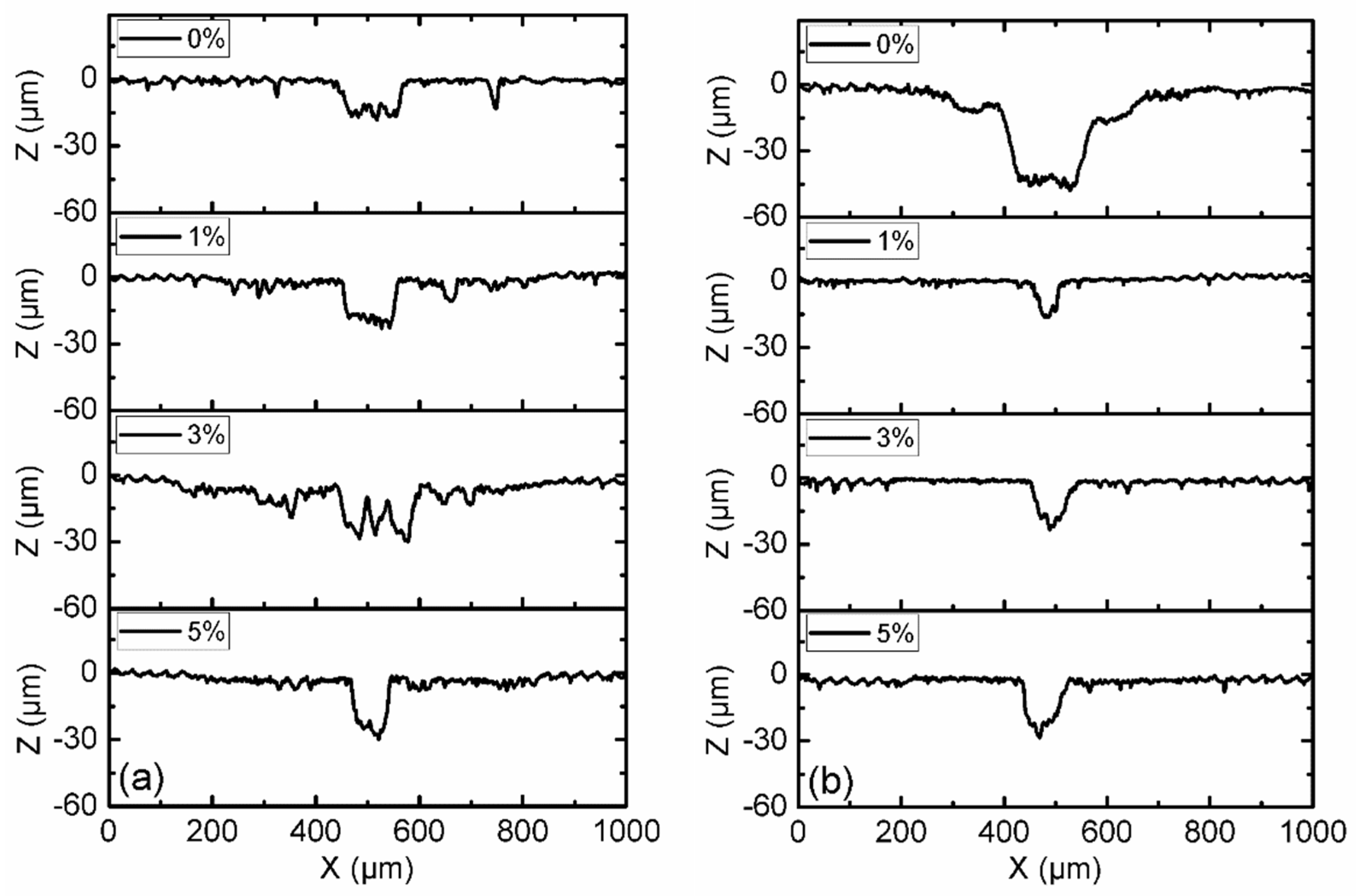
Figure 11.
SEM of MRFs with different ND additives content before and after tests: (a) 0, (b) 1, (c) 3, (d) 5 wt.%.
Figure 11.
SEM of MRFs with different ND additives content before and after tests: (a) 0, (b) 1, (c) 3, (d) 5 wt.%.
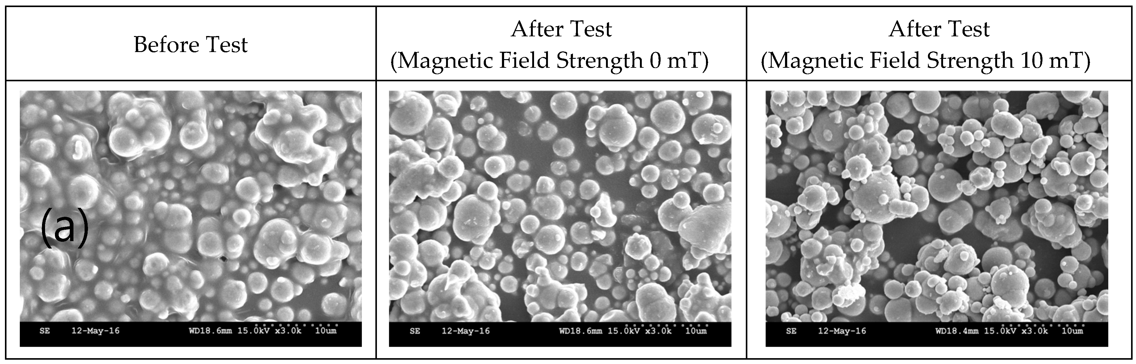
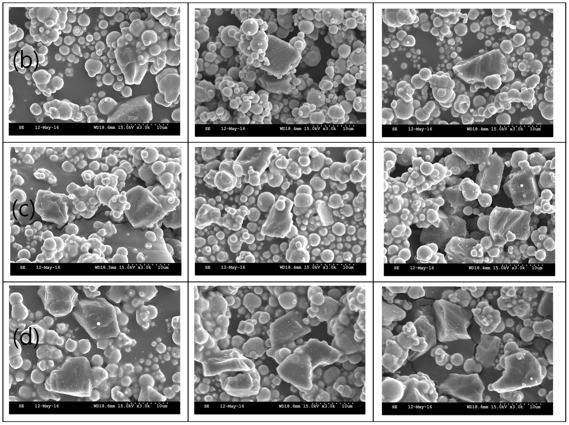
Figure 12.
SEM of MRFs with different MoS2 additives content before and after tests: (a) 0, (b) 1, (c) 3, (d) 5 wt.%.
Figure 12.
SEM of MRFs with different MoS2 additives content before and after tests: (a) 0, (b) 1, (c) 3, (d) 5 wt.%.
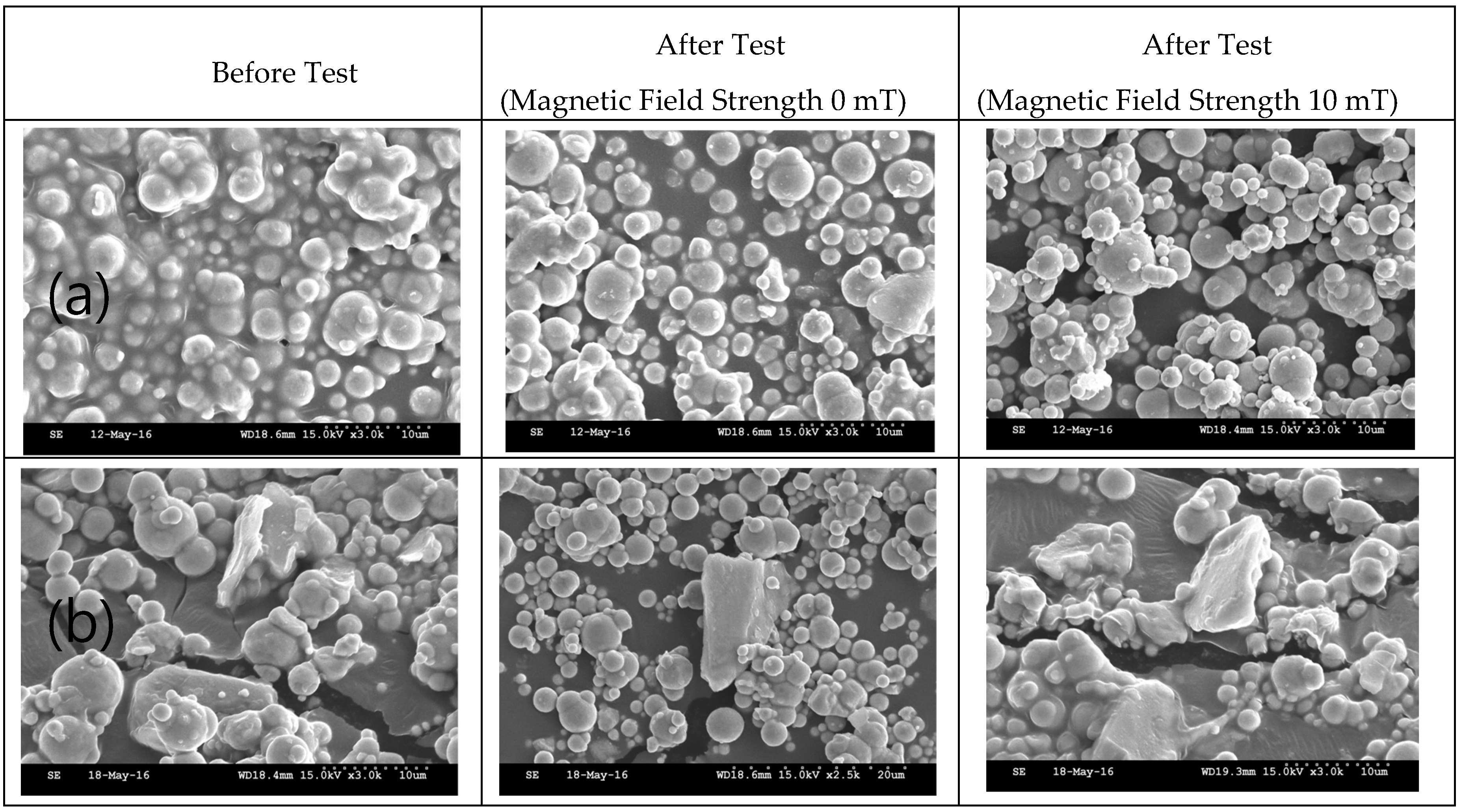
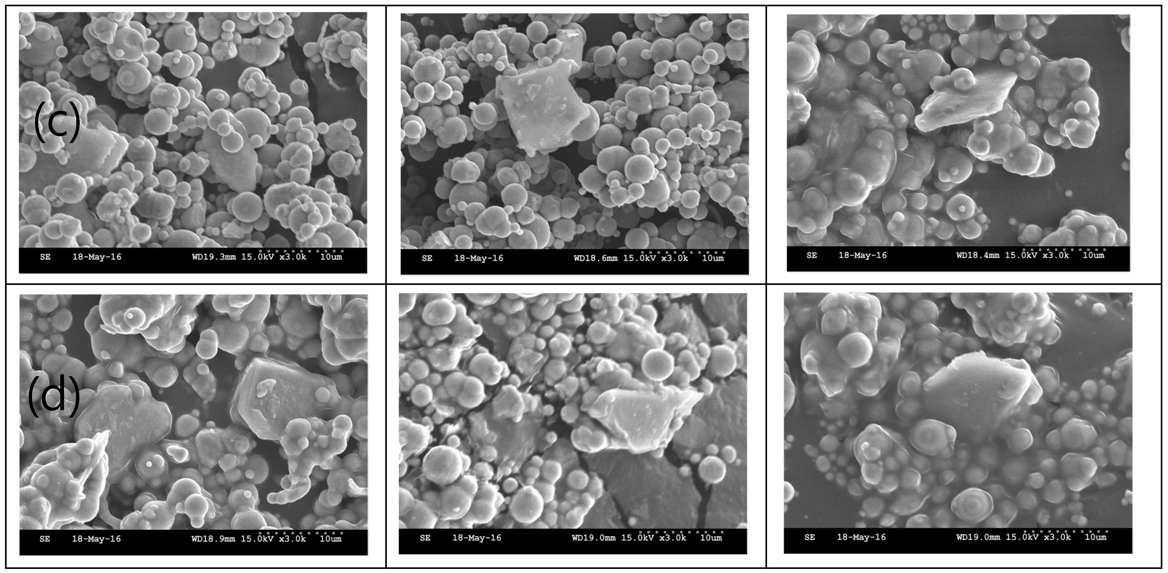
Figure 13.
EDX of MRFs with ND additives: (a) 0, (b) 1, (c) 3, (d) 5 wt.%.
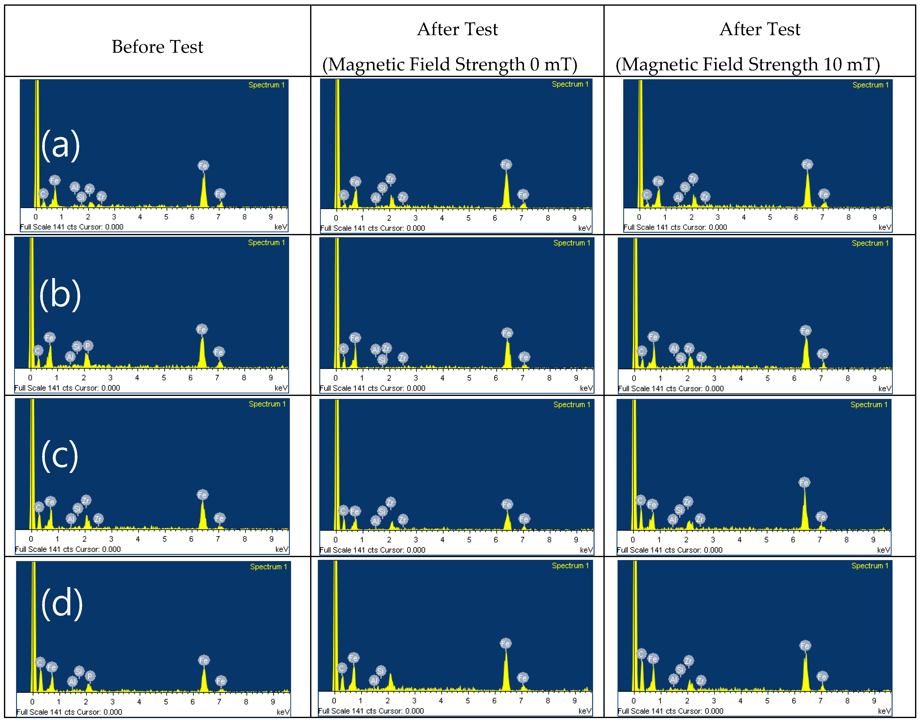
Figure 14.
EDX of MR fluids with MoS2 additives: (a) 0, (b) 1, (c) 3, (d) 5 wt.%.
Disclaimer/Publisher’s Note: The statements, opinions and data contained in all publications are solely those of the individual author(s) and contributor(s) and not of MDPI and/or the editor(s). MDPI and/or the editor(s) disclaim responsibility for any injury to people or property resulting from any ideas, methods, instructions or products referred to in the content. |
© 2024 by the authors. Licensee MDPI, Basel, Switzerland. This article is an open access article distributed under the terms and conditions of the Creative Commons Attribution (CC BY) license (http://creativecommons.org/licenses/by/4.0/).
Copyright: This open access article is published under a Creative Commons CC BY 4.0 license, which permit the free download, distribution, and reuse, provided that the author and preprint are cited in any reuse.


