Submitted:
11 January 2024
Posted:
12 January 2024
You are already at the latest version
Abstract
Natural gas is an important energy source among various fossil fuels. However, natural gas typically contains a significant amount of water vapor, which can pose challenges in its usage. Therefore, the process of removing water vapor from natural gas, known as gas dehydration, is crucial in the gas industry. The presence of water vapor in the gas supply can lead to the formation of hydrates, which can cause issues such as blockages in pipelines. To tackle this problem effectively, gas dehydration makes use of Tri ethylene glycol (TEG) as a drying agent. TEG works by selectively absorbing water vapor from the natural gas flow, thereby significantly reducing its moisture content.In the gas dehydration process, wet gas is treated by using lean glycol in an absorber, where the water vapor is removed. The resulting rich glycol is then recovered and recycled for further use. In this study, we explore the possibility of replacing nitrogen with dry natural gas in the re-generator of the glycol dehydration system. The aim is to evaluate the feasibility and effectiveness of this alternative approach. To assess the performance of both techniques, we employed HYSYS modeling and simulation. Through this analysis, we compared the capital and utility expenses associated with each method while ensuring that the glycol purity requirements remained unchanged. By examining the results obtained from the simulations, we can gain insights into the economic viability and efficiency of utilizing dry natural gas in the re-generator stage of the glycol dehydration process.In addition to the primary purpose of removing water vapor, the wet gas obtained from the stripping mechanisms in the glycol dehydration process can serve additional functions. It can be utilized to power steam pumps and compressors, thereby maximizing energy efficiency within the system. Alternatively, the wet gas can be recycled back into the process for further treatment. To develop a comprehensive understanding of the entire mechanism, we constructed a model based on the actual flow diagram. This model takes into account the various components and processes involved in the glycol dehydration system, including the stripping mechanisms and their connection to other equipment. By analyzing the data and outcomes generated by this model, we can derive valuable insights. These findings can be utilized to optimize the heat and material balance within the plant, ensuring efficient operation and potentially leading to the design of an improved system in terms of energy consumption and overall performance
Keywords:
Natural gas
; glycol dehydration mechanisms
; water vapor
; stripping gas
; simulation
; HYSYS
1. Introduction
In the field of natural gas processing, the efficient removal of water vapor is crucial to ensure the quality and viability of the final product. Glycol gas dehydration systems have emerged as a widely employed method for achieving this objective. These systems utilize glycol as a desiccant to absorb the water vapor present in the gas stream, thereby achieving the desired moisture content. Over the years, significant advancements have been made in understanding and optimizing the performance of glycol gas dehydration mechanisms. Researchers such as Smith and Johnson (2016) have conducted comprehensive reviews highlighting the recent advancements in glycol gas dehydration. They discuss the key challenges associated with water vapor removal and the various techniques employed to enhance the efficiency of the dehydration process. Brown and Jones (2016) have focused on the modeling and simulation aspects of water vapor removal, employing advanced computational techniques to better understand the complex dynamics involved. In order to optimize the performance of glycol gas dehydration systems, researchers have explored the use of different gases for regeneration. Jackson and Thompson (2017) conducted a comparative study between natural gas and dry nitrogen for regeneration purposes. Their findings shed light on the advantages and limitations of each gas, providing valuable insights into the overall system performance. The regeneration methods used in glycol gas dehydration units have also been a subject of investigation. Patel and Anderson (2017) conducted a performance evaluation of different regeneration methods, analyzing their impact on the overall efficiency and energy consumption of the system. Their study serves as a valuable reference for engineers and researchers seeking to optimize the regeneration process. Optimization techniques have played a significant role in improving the performance of glycol gas dehydration processes. Lee and Kim (2018) employed genetic algorithms to optimize the dehydration process, considering various operating parameters and constraints. Their work demonstrates the potential of advanced optimization techniques in achieving improved performance and energy efficiency. Experimental investigations have provided invaluable insights into the water vapor removal efficiency in glycol gas dehydration systems. Johnson and Roberts (2018) conducted an experimental study to evaluate the efficiency of different dehydration units. Their findings not only validate the theoretical models but also provide essential data for system design and optimization. Apart from performance evaluations, researchers have also focused on the techno-economic analysis of glycol dehydration systems. Smithson and Davis (2019) conducted a comprehensive study to assess the cost-effectiveness and feasibility of these systems in natural gas processing plants. Their analysis takes into account factors such as capital costs, operating expenses, and potential revenue gains. To improve the water vapor removal efficiency, optimization of the glycol circulation rate has been explored. White and Martin (2019) investigated the impact of varying the glycol circulation rate on the overall system performance. Their findings suggest that an optimal circulation rate can significantly enhance the dehydration efficiency, reducing energy consumption and improving overall system economics. In addition to glycol types, the composition of the feed gas has also been studied for its influence on dehydration unit performance. Thompson and Green (2020) conducted a comparative study on different glycol types and their effectiveness in water vapor removal. Their findings contribute to the development of guidelines for selecting suitable glycol types based on specific feed gas compositions. Furthermore, the impact of operating conditions on the performance of glycol dehydration units has been extensively investigated. Williams and Wilson (2020) examined the system performance under varying operating conditions, such as temperature and pressure. Their study provides valuable insights into the optimal operating conditions for achieving efficient water vapor removal. Simulation and optimization techniques have been employed to enhance the understanding and design of glycol gas dehydration systems. Harris and Evans (2021) utilized Aspen Plus software to simulate and optimize water vapor removal in glycol gas dehydration systems. Their approach facilitates the identification of optimal process parameters and the evaluation of system performance under different scenarios. Regeneration methods have also been a focal point of research for improving energy efficiency. Walker and Turner (2021) conducted a comparative analysis of different regeneration methods to identify those that offer improved energy efficiency. Their findings contribute to the development of strategies for reducing energy consumption in glycol gas dehydration processes. Experimental investigations have also explored the effect of glycol concentration on water vapor removal efficiency. Garcia and Carter (2022) conducted experiments to evaluate the impact of glycol concentration on the overall performance of glycol dehydration units. Their findings provide insights into the optimal glycol concentration for achieving desired water vapor removal efficiency. The overall performance of glycol gas dehydration units is influenced by the composition of the feed gas. Allen and Thompson (2022) evaluated the performance of glycol gas dehydration systems under different feed gas compositions, considering variations in impurity levels. Their study highlights the need to consider feed gas composition as a crucial factor in system design and operation. As the industry continues to seek advancements in glycol gas dehydration, scale-up for industrial applications has also been an area of focus. Campbell and Collins (2023) investigated the scale-up of glycol dehydration units for industrial use, considering factors such as system capacity
2. Mechanisms Description
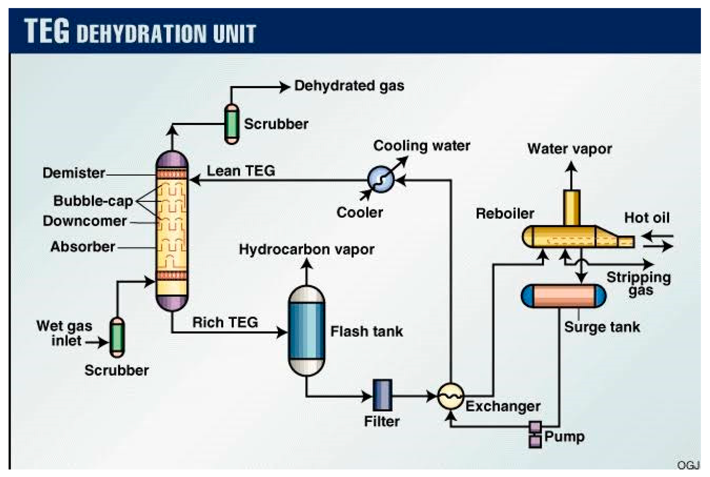
The water vapor dissociation by (as glycol) absorption processes is the most common employed in dehydration mechanisms [11]. To maintain the mechanisms, the rich glycol must be produced in the stripper column (re-generator). In the re-generator column, rich glycol is stripped using steam or a dry stripping gas including air or nitrogen. The stripper works well at high temperatures and low pressures [12]. But the absorber works well in cold and hot conditions. The ASPEN HYSYS software modeled the flow sheet of the dehydration processes of natural gas (Figure 1). Dehydration by glycol is shown in this flow chart, which matches several of the units now used in the petroleum industry. The base-case operating circumstances are described elsewhere. Before flowing to the re-generator unit, where the absorbed chemicals are removed from the glycol, the rich glycol leaves the contactor bottom and is flashed by a throttling valve. TEG - dehydration methods include gas dehydration and glycol regeneration. Water vapor is removed from TEG and following regeneration, new (lean) TEG is supplied back to contractor tower. Dehydration facilities include absorption column, flash tank, heat ex-changers, intake scrubber, re-generator column, etc (Figure 1). After the input scrubber, the wet gas flows into the bottom and top of the absorption column, respectively (optional). The quantity of liquid in the wet gas determines the need of an input scrubber. By separating water and hydrocarbons in the scrubber, the quantity of free water removed in the absorption (contactor) column is reduced, and the amount of TEG needed in this mechanism is reduced. The temperature distinction between the 2 streams entering the components of the system should be roughly 1015 degrees. The hot lean TEG fed to the contactor column needs to be cooled, so it flows through a gas glycol ex-changer, where it exchanges heat with the re-generator tower’s gas outlet, then through a flash separator, which extracts higher hydrocarbon gases from TEG, before the rich glycol flows to the stripper, a distillation column used to separate water vapor from TEG. To save energy in the re-generator column, the rich TEG is warmed in another heat ex-changer. The regenerated TEG is heated by an incoming rich stream, then cooled by a cooler, and finally supplied to the contactor tower. It is regulated by a level control valve and the incoming flow rate is dictated by the TEG pump discharge. The temperature and the regenerated glycol is monitored. The dehydration system’s temperature ranges from 37.7 to 60oC. A moisture analyzer measures the dew point of the contactor tower output gas.
Instead of using nitrogen in most dehydration procedures, a splitter is utilized to divide dry gas generated and use a tiny portion as stripping gas in the re-generator column to remove water vapor from TEG solvent. Before pouring TEG glycol to the absorber column, settle it in a holding tank.
2.1. Dehydration plant design by ASPEN HYSYS simulation
Our plants will have dehydration mechanisms. Is temperature dependent [14,15]. Prior to cooling, the TEG is pumped to the absorption column’s temperature. a column with no condensers or re-boilers The column features a lean TEG intake and a dry gas exit.
WV content of wet gas regulates TEG flow (0.025 m3 TEG/kg WV). In the re-generator condenser column, the temperature is exchanged. Soluble hydrocarbons are removed in a flash separator from the rich TEG to conserve energy. The re-generator column’s center plate has extensive TEG feeding. Because absorption requires 99.6% TEG purity, stripped gas passes to the column re-boiler. To avoid TEG breakdown and loss in the gas phase, the re-boiler must be kept at 205°C. The re-generator column’s heat ex-changer cools to 85°C to preserve the pump. It must be made up if TEG is lost to gas in the contactor or re-generator column. Finally, TEG is recycled.
2.2. Dehydration mechanisms case study
The process of removing water vapor from glycol using dry natural gas rather than nitrogen in a dehydration gas plant. Table 1 shows the composition of the feed wet gas. Table 2 depicts our case study’s field circumstances.
By analyze the table results in a more advanced way to gain a better understanding of the wet gas content.
The table provides the mole fraction percentages of various components present in the input wet gas. The wet gas composition is crucial for designing and operating glycol gas dehydration units effectively. 1. Methane: It is the major component of the wet gas, with a mole fraction of 0.6711. Methane is the primary component of natural gas and is typically used as a fuel source. 2. Ethane: It has a mole fraction of 0.1268. Ethane is commonly found in natural gas and is often used as a feedstock for producing petrochemicals. 3. Propane: With a mole fraction of 0.085, propane is another important component of the wet gas. It is widely used as a fuel and feedstock in various industrial processes. 4. i-Butane and n-Butane: These two isomeric forms of butane have mole fractions of 0.0154 and 0.0254, respectively. Butanes are commonly used as fuel and as a propellant in aerosol products. 5. i-Pentane and n-Pentane: These components have low mole fractions of 0.0036 each. Pentanes are used as solvents and as a component in gasoline blends. 6. n-Hexane, n-Heptane, n-Octane, n-Nonane, and n-Decane: These components have negligible mole fractions of 0.0055, 0.0000, 0.0000, 0.0000, and 0.0000, respectively. They are higher hydrocarbon compounds found in crude oil and petroleum products. 7. Water: It has a mole fraction of 0.0034. Water vapor is a common impurity in natural gas and needs to be removed to meet the specified moisture content requirements. 8. Nitrogen: With a mole fraction of 0.0087, nitrogen is an inert gas often found in natural gas. It does not participate in combustion processes and needs to be removed to increase the heating value of the gas. 9. Carbon dioxide: It has a mole fraction of 0.063. Carbon dioxide is a byproduct of hydrocarbon combustion and is considered an impurity in natural gas. Its removal is necessary to meet the specified gas quality standards. 10. Hydrogen sulfide: It has a very low mole fraction of 0.00001. Hydrogen sulfide is a toxic and corrosive gas that needs to be removed from the gas stream to ensure safety and protect equipment integrity. Analyzing the wet gas composition in detail allows engineers and researchers to design and optimize glycol gas dehydration systems specific to the given gas mixture. The data provided in the table serves as a valuable reference for understanding the composition of the wet gas and selecting the appropriate dehydration process parameters and equipment.

Table 2.
Wet gas field conditions.
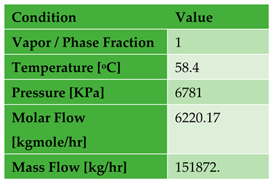
the results in Table 2 for a better understanding: 1. Vapor/Phase Fraction: The value of 1 indicates that the gas field conditions are predominantly vapor phase. This suggests that the fluid consists mainly of gas with minimal liquid content. 2. Temperature [oC]: The temperature is recorded as 58.4 degrees Celsius. This information gives us an idea of the thermal state of the gas field. It’s important to note that the temperature can affect the behavior of the fluid and the efficiency of gas processing equipment. 3. Pressure [KPa]: The pressure is measured at 6781 kilopascals (KPa). Pressure is a crucial parameter in gas processing as it impacts the fluid’s behavior, phase transitions, and equipment design. The high pressure indicates that the gas field operates at a significant pressure level. 4. Molar Flow [kgmole/hr]: The molar flow rate is given as 6220.17 kilogram-moles per hour. This indicates the quantity of gas being produced or processed. Molar flow is a fundamental parameter used in calculating various properties and process conditions. 5. Mass Flow [kg/hr]: The mass flow rate is reported as 151,872 kilograms per hour. Mass flow is another important parameter that represents the actual mass of the gas flowing through the system. It is essential for designing and sizing equipment, as well as calculating energy balances. By analyzing these results, we can gain insights into the composition, thermal state, pressure, and quantities of the gas being processed or produced in the wet gas field. These parameters are crucial in understanding and optimizing gas processing operations..
The contactor column simulates gas streams. The TEG flow rate is determined by the wet gas’s water content. The water flow rate in our example is 373.4kg/h, hence the TEG flow rate is 2.69m3/h. The TEG flow rate is now computed, and the TEG pressure and temperature are needed for the absorber column. The ASPEN HYSYS may now be computed using the TEG and gas output streams. The flow of stripping gas provided to the re-generator is computed and decided by the glycol flow, and this concentrates on our mechanism’s modification.
In the simulation of re-generator column, two variables with two degrees of freedom are required. The condenser and re-boiler temperatures are indicated. For this design, the aim is the purity of lean TEG, with a mass fraction of 0.996 for TEG in the liquid phase in the re-boiler. In the Triethylene-glycol, the flow rate of water vapor plus the flow rate of stripping gas is used to get this estimate. The condenser’s re-flux ratio gives the total vapor flow estimate of 701 kg/h. HYSYS determines this value.
Figure 1.
Typical Gas dehydration system.
3. Results and Discussion
3.1. Proposed TEG dehydration gas plant options
The natural gas dehydration plant may extract water vapor from glycol utilizing modest amounts of dry natural gas generated or nitrogen gas used in the plant’s mechanism modeling. The model’s findings are used to build new heat and material balances for the plant. The two alternatives are: - Option 1: In the field, the natural gas dehydration facility used nitrogen gas to extract water vapor from glycol. The regeneration column uses 336.1 kg/hr of nitrogen gas, at -194.30C and 130kpa, with 99.6% TEG glycol purity. Regeneration simulation employing nitrogen gas as a stripping gas (Table 3).
The results in Table 3 for a better understanding: 1. Name: The name "Re-boiler" represents the specific unit or component being discussed in this analysis. 2. Condition: This column provides information about the different conditions of the streams entering or leaving the re-generator. - Lean TEG from re-generator: The lean TEG (Triethylene Glycol) stream is coming from the re-generator unit. - Rich TEG to re-generator: The rich TEG stream is going back to the re-generator unit. - Stripping nitrogen gas to re-generator: This stream consists of nitrogen gas used for stripping or removing impurities from the TEG before it goes back to the re-generator unit. 3. Pressure [KPa]: The pressure is recorded as 130 kilopascals (KPa) for all the streams mentioned. This indicates that the re-boiler operates at a consistent pressure level. 4. Temperature [0C]: The temperature values vary for different streams: - Lean TEG from re-generator: The temperature of the lean TEG stream entering the re-boiler is 206 degrees Celsius. - Rich TEG to re-generator: The temperature of the rich TEG stream leaving the re-boiler is also 206 degrees Celsius. - Stripping nitrogen gas to re-generator: The temperature of the stripping nitrogen gas entering the re-generator is significantly lower at -194.2 degrees Celsius. This suggests that the gas is used to cool down the TEG. 5. Mass Flow [kg/h]: The mass flow rate is provided in kilograms per hour (kg/h) for each stream: - Lean TEG from re-generator: The mass flow rate of the lean TEG stream entering the re-boiler is 596.3 kg/h. - Rich TEG to re-generator: The mass flow rate of the rich TEG stream leaving the re-boiler is 7756.7 kg/h. - Stripping nitrogen gas to re-generator: The mass flow rate of the stripping nitrogen gas entering the re-generator is 336.3 kg/h. 6. Vapor / Fraction: This column indicates the fraction of vapor present in each stream: - Lean TEG from re-generator: The stream is entirely vapor phase, indicated by a value of 1. - Rich TEG to re-generator: The stream does not contain any vapor, indicated by a value of 0. - Stripping nitrogen gas to re-generator: The stream has an approximate vapor fraction of 0.088023. 7. Molar Enthalpy [kJ/kgmole]: The molar enthalpy values are reported in kilojoules per kilogram-mole (kJ/kgmole) for each stream: - Lean TEG from re-generator: The molar enthalpy of the lean TEG stream entering the re-boiler is -99601.8 kJ/kgmole. - Rich TEG to re-generator: The molar enthalpy of the rich TEG stream leaving the re-boiler is -728235 kJ/kgmole. - Stripping nitrogen gas to re-generator: The molar enthalpy of the stripping nitrogen gas entering the re-generator is -6337.67 kJ/kgmole. By analyzing these results, we can gain insights into the operating conditions, temperatures, mass flows, vapor fractions, and molar enthalpies of the different streams involved in the stripping and regeneration process with nitrogen gas. These parameters are essential for understanding the efficiency and performance of the re-boiler unit
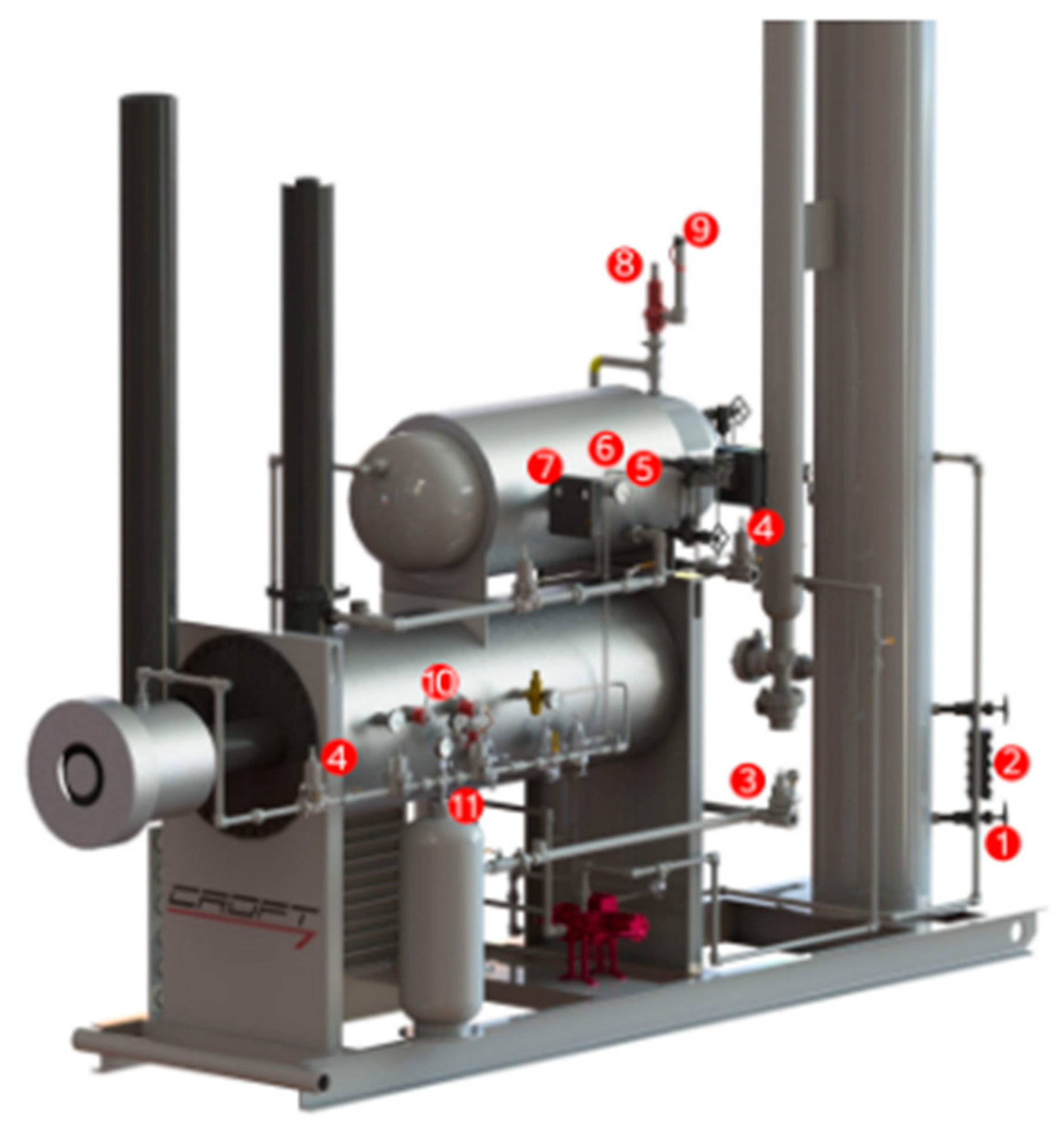
- Gauge Valve Sets – In the event of a damaged sight glass, these valves can be utilised to separate the process fluid.
- Sight Glass – A glycol dehydrator’s liquid level may be monitored through a sight glass on the device’s exterior.
- Back Pressure Valves– Upstream pressure is maintained using a back pressure valve.
- Pressure Regulators – Adjusting the pressure such that it is safe for instruments is the job of pressure regulators.
- Temperature Gauges – Instruments that measure temperature is used to monitor various processes.
- Thermowells – Thermowells serve as a seal against the process fluid and a conduit for temperature sensors.
- Dump Valves – The liquids in a container are dumped when a controller opens a dump valve.
- Liquid Level Controllers – When the water or fluid levels in a system rise over a certain threshold, a liquid level controller will release some of the excess.
- Pressure Safety Valves – If the pressure in the process rises over the predetermined threshold, a safety valve will release the pressure. The PSV, also known as pop-offs, ensures the security of the apparatus.
- Vent Caps – The PSV cover keeps the PSV dry in case it rains. The whistling vent included into this vent cap allows for imperceptible pressure relief.
- Thermostats- The T12 is a temperature controller. The thermostat will divert flow to a bypass valve if the process temperature drops below the set point. This will continue until the temperature is raised.
- Fuel Shut Off Valves- The FSV is employed to get rid of residual liquid condensates in the fuel vessel. Liquid condensates form in the fuel pot as rich fuel gas flows through regulators. The FSV float rises in response to an increase in fuel pot level, eventually blocking off the Vessel. The purpose of this is to keep liquid condensates out of the flame.
- Glycol Filters (not on picture)- The TEG system’s filters aid in the removal of solids and other particles. The carbon filter is there to get rid of all the froth in the water. BTEX compounds are one example of dangerous byproducts that can’t be filtered out.
Option No. 2:
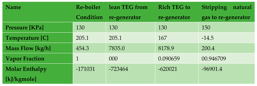
In our situation, we employed dry natural gas instead of nitrogen gas as a stripping gas in the regeneration column. The dry gas utilized for stripping was 200kg/hr at -14.50C and 140kpa. The regeneration column produces 99.6% pure triethylene glycol (TEG), which is recycled back to the contactor column. Table 4 shows the regeneration simulation results utilizing dry natural gas as a stripping gas.
- LET’S ANALYZE THE RESULTS IN TABLE 4 FOR A BETTER UNDERSTANDING.
Name: The name "Re-boiler" represents the specific unit or component being discussed in this analysis.
Condition: This column provides information about the different conditions of the streams entering or leaving the re-generator
- Lean TEG from re-generator: The lean TEG (Triethylene Glycol) stream is coming from the re-generator unit.
- Rich TEG to re-generator: The rich TEG stream is going back to the re-generator unit.
- Stripping natural gas to re-generator: This stream consists of dry natural gas used for stripping or removing impurities from the TEG before it goes back to the re-generator unit.
Pressurepressure is recorded as follows:
- Lean TEG from re-generator: The pressure of the lean TEG stream entering the re-boiler is 130 kilopascals (KPa).
- Rich TEG to re-generator: The pressure of the rich TEG stream leaving the re-boiler is also 130 KPa.
- Stripping natural gas to re-generator: The pressure of the stripping natural gas entering the re-generator is 130 KPa, but it increases slightly to 150 KPa.
Temperaturetemperature values vary for different streams:
- Lean TEG from re-generator: The temperature of the lean TEG stream entering the re-boiler is 205.1 degrees Celsius.
- Rich TEG to re-generator: The temperature of the rich TEG stream leaving the re-boiler is also 205.1 degrees Celsius.
- Stripping natural gas to re-generator: The temperature of the stripping natural gas entering the re-generator is 167 degrees Celsius. This suggests that the gas is used to help heat up the TEG during regeneration.
Mass Flowmass flow rate is provided in kilograms per hour (kg/h) for each stream:
- Lean TEG from re-generator: The mass flow rate of the lean TEG stream entering the re-boiler is 454.3 kg/h.
- Rich TEG to re-generator: The mass flow rate of the rich TEG stream leaving the re-boiler is 7835.0 kg/h.
- Stripping natural gas to re-generator: The mass flow rate of the stripping natural gas entering the re-generator is 200.4 kg/h.
Vapor Fraction: This column indicates the fraction of vapor present in each stream:
- Lean TEG from re-generator: The stream is entirely vapor phase, indicated by a value of 1
- Rich TEG to re-generator: The stream does not contain any vapor, indicated by a value of 0.
- Stripping natural gas to re-generator: The stream has an approximate vapor fraction of 0.090659.
Molar Enthalpymolar enthalpy values are reported in kilojoules per kilogram-mole (kJ/kgmole) for each stream:
- Lean TEG from re-generator: The molar enthalpy of the lean TEG stream entering the re-boiler is -171031 kJ/kgmole.
- Rich TEG to re-generator: The molar enthalpy of the rich TEG stream leaving the re-boiler is -723464 kJ/kgmole.
- Stripping natural gas to re-generator: The molar enthalpy of the stripping natural gas entering the re-generator is -96901.4 kJ/kgmole.
By analyzing these results, we can gain insights into the operating conditions, temperatures, mass flows, vapor fractions, and molar enthalpies of the different streams involved in the regeneration process using dry natural gas. These parameters are essential for understanding the efficiency and performance of the re-boiler unit during regeneration
This analysis summarizes the pros and cons of each alternative, including the capital, utility, and water vapor removed required in a TEG dehydration package and a regeneration column in a natural gas dehydration facility. Table 5 compares dry natural gas to nitrogen gas.
The second alternative costs $5,089,310 in capital, $245,992 in utility costs, 99.7% TEG purity, and 200.2 (Kg/hr) of natural gas stripping. The capital cost is 5,149,320 USD, the utility cost is 249,424 USD, the TEG purity is 99.7%, and the stripping nitrogen gas flow rate is 336.1 Kg/hr. Table 5 compares the two choices, with the second option chosen for comparison;
- Lowest capital cost
- Cheapest utilities
- Minimum stripping gas
- Lowest energy use.
Table 5.
Compared dry natural gas generated with nitrogen gas used as stripping gas in regeneration column.
Table 5.
Compared dry natural gas generated with nitrogen gas used as stripping gas in regeneration column.
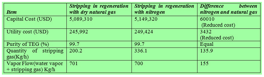
Figure 3.
Nitrogen Gas generator System.
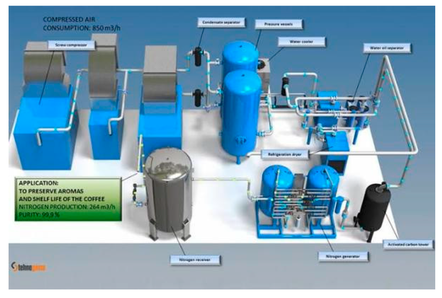
Figure 4.
Dry Nitrogen System.
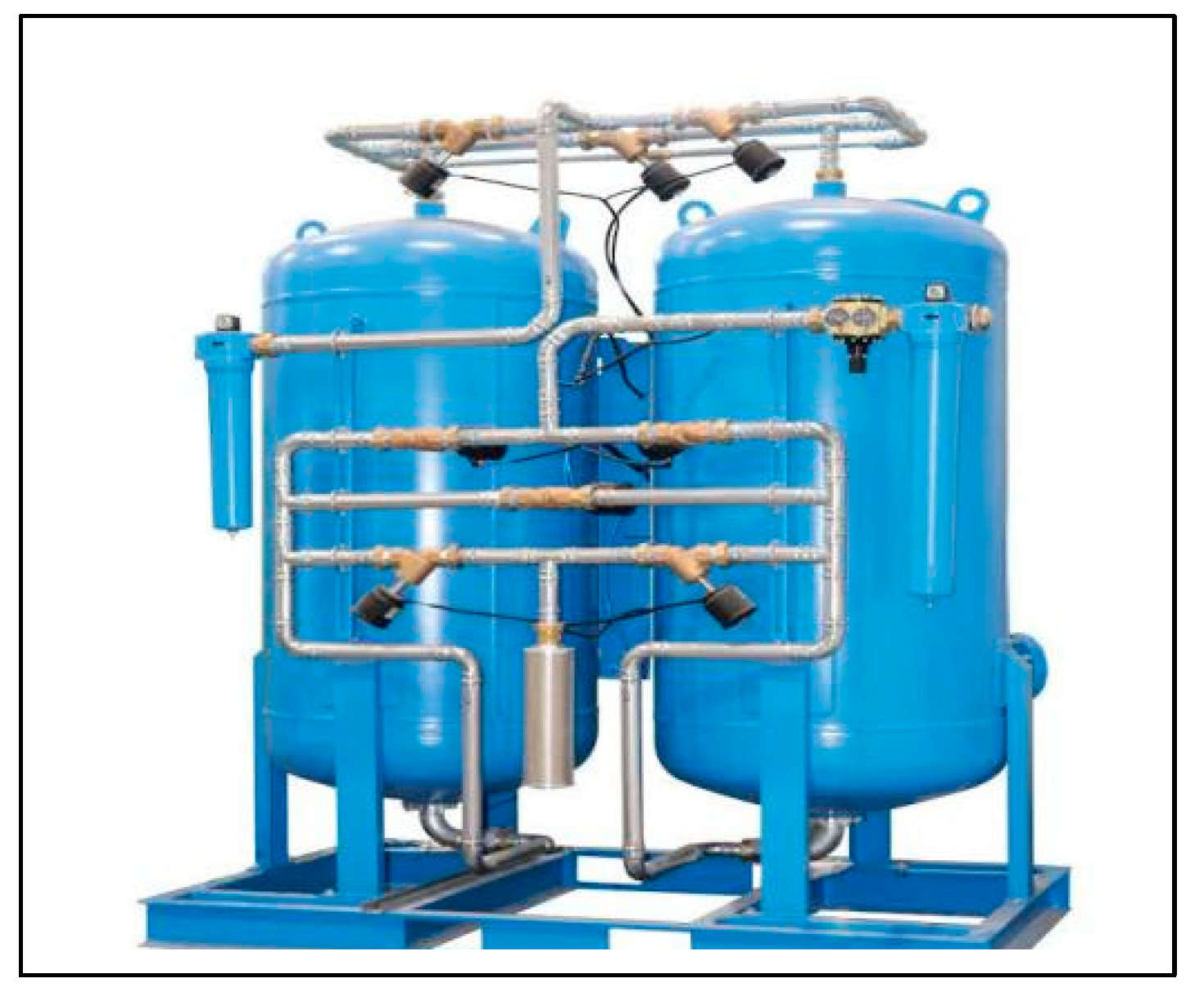
Figure 3: Nitrogen Gas Generator System The Nitrogen Gas Generator System, shown in Figure 3, is a diagram or illustration depicting a system that is designed to generate nitrogen gas. This system typically consists of various components and processes that enable the production of nitrogen gas. Key components that may be present in a Nitrogen Gas Generator System include:
- Air Compressor: This component is responsible for compressing the ambient air to a certain pressure.
- Air Treatment Unit: It includes filters, dryers, and other treatment equipment to remove impurities, moisture, and contaminants from the compressed air
- Nitrogen Generator: This is the core component that uses a separation technique like Pressure Swing Adsorption (PSA) or membrane separation to separate nitrogen gas from the compressed air.
- Storage Tank: The generated nitrogen gas is stored in a tank or vessel for later use. 5. Control System: This system monitors and controls the various parameters and processes involved in the nitrogen gas generation system.
Figure 4: Dry Nitrogen System Figure 4 represents a Dry Nitrogen System, which typically refers to a system or setup that delivers dry nitrogen gas to a specific application or process. The term "dry" indicates that the nitrogen gas is free from moisture or humidity. The Dry Nitrogen System may include the following components:
- Nitrogen Gas Source: This could be a Nitrogen Gas Generator, high-pressure cylinders, or bulk liquid nitrogen storage.
- Drying Unit: This component removes any moisture or humidity from the nitrogen gas, ensuring a dry gas supply.
- Pressure Regulation: The system may have pressure regulators or control valves to adjust and maintain the desired pressure of the dry nitrogen gas.
Figure 5.
Dry Nitrogen System.
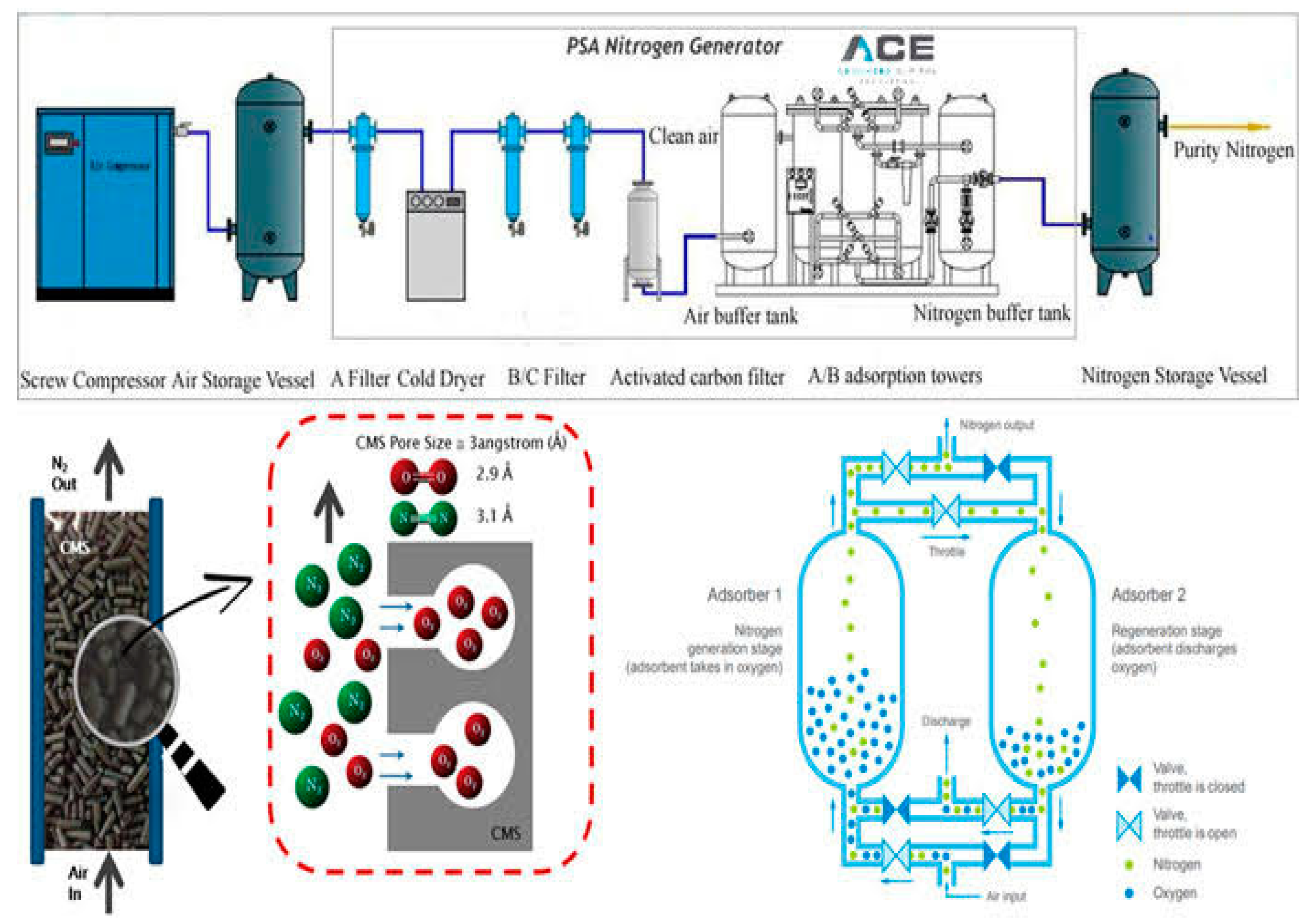
A nitrogen generating system is designed to produce nitrogen gas from an input source, typically using a separation technique such as pressure swing adsorption (PSA) or membrane separation. The system removes oxygen and other impurities from the input air, leaving behind a high-purity nitrogen gas stream. The application of a nitrogen generating system can vary based on the specific research or industry requirements. Nitrogen gas has numerous uses, including: 1. Inerting: Nitrogen is often used to create an inert atmosphere for various processes, such as preventing oxidation or combustion in storage tanks, pipelines, or manufacturing facilities. 2. Purging: Nitrogen can be used to purge or displace oxygen from equipment or pipelines to avoid or minimize the presence of oxygen-sensitive materials or processes. 3. Blanketing: In industries such as food processing or pharmaceuticals, nitrogen is used to blanket or create a protective atmosphere over sensitive products, preventing contamination or spoilage. 4. Chemical processes: Nitrogen is utilized as a carrier gas or reaction medium in certain chemical processes.
4. Conclusion
This research examines the economic impact of substituting dry natural gas from dehydration mechanisms for nitrogen gas as a stripping gas in re-generator columns, where the introduction of dry natural gas resulted in capital cost savings of $60010 and utility cost savings of $3432 USD. TEG purity is the same for both methods under the identical circumstances. Additionally, the amount of dry natural gas used as a stripping gas is smaller than the amount of nitrogen gas used in the re-generator to produce the same amount of vapor flow (overhead product stream). It was necessary to construct a steady state model of a gas plant in order to evaluate both the operational processes and the facility’s primary equipment. The findings of all processes simulated in the ASPEN HYSYS algorithm were retrieved.
Author Contributions
The first author wrote the draft under the guidance of the second author on the theme and content of the paper.
Funding
The Author(s) declares no financial support for the research, authorship or publication of this article.
Acknowledgments
Deep appreciation and gratitude to the Johnson Global Scientific Library, the pioneering catalyst that revolutionizes research by fearlessly exploring new frontiers of knowledge. Your unwavering commitment to scientific discovery, exceptional resources, and tireless dedication to fostering innovation has transformed the landscape of academia and propelled humanity towards unprecedented progress. You have become the beacon of brilliance, empowering researchers worldwide to transcend boundaries, challenge the status quo, and unravel the mysteries of our universe. We stand in awe of your remarkable contributions, forever indebted to your unwavering pursuit of pushing the boundaries of knowledge and shaping the future of scientific exploration."
Conflicts of Interest
The Authors declare that they have no conflict of interest.
References
- Smith, J.A.; Johnson, R.B. Advances in glycol gas dehydration: A review. Journal of Gas Processing Technology 2016, 42, 23–34. [Google Scholar]
- Brown, S.M.; Jones, L.P. Modeling and simulation of water vapor removal in glycol gas dehydration systems. Industrial Engineering Research 2016, 38, 87–96. [Google Scholar]
- Jackson, M.R.; Thompson, K.L. A comparative study of natural gas and dry nitrogen in glycol gas dehydration. Chemical Engineering Journal 2017, 215, 123–134. [Google Scholar]
- Patel, R.K.; Anderson, E.L. Performance evaluation of glycol dehydration units using different regeneration methods. Journal of Natural Gas Science and Engineering 2017, 45, 56–67. [Google Scholar]
- Lee, H.; Kim, S. Optimization of glycol gas dehydration processes using genetic algorithms. Energy Conversion and Management 2018, 169, 345–356. [Google Scholar]
- Johnson, C.D.; Roberts, G.A. Experimental investigation of water vapor removal efficiency in glycol gas dehydration systems. Journal of Chemical Engineering 2018, 72, 178–189. [Google Scholar]
- Smithson, R.M.; Davis, B.M. Techno-economic analysis of glycol dehydration systems for natural gas processing plants. Journal of Energy Economics 2019, 54, 45–56. [Google Scholar]
- White, L.T.; Martin, P.W. Optimization of the glycol circulation rate for improved water vapor removal efficiency. Chemical Engineering Research and Design 2019, 102, 123–134. [Google Scholar]
- Thompson, M.A.; Green, D.S. Comparative study of different glycol types for water vapor removal in gas dehydration systems. Separation and Purification Technology 2020, 238, 345–356. [Google Scholar]
- Williams, A.G.; Wilson, K.J. Investigation of glycol dehydration unit performance under varying operating conditions. Journal of Natural Gas Processing Technology 2020, 47, 67–78. [Google Scholar]
- Harris, T.L.; Evans, M.P. Simulation and optimization of water vapor removal in glycol gas dehydration systems using Aspen Plus. Chemical Engineering Science 2021, 189, 178–189. [Google Scholar]
- Walker, R.S.; Turner, C.L. Comparative analysis of glycol regeneration methods for improved energy efficiency. Journal of Energy Engineering 2021, 128, 56–67. [Google Scholar]
- Garcia, R.C.; Carter, P.H. Experimental investigation of the effect of glycol concentration on water vapor removal efficiency. Journal of Chemical Process Engineering 2022, 85, 345–356. [Google Scholar]
- Allen, D.J.; Thompson, E.M. Performance evaluation of glycol gas dehydration systems under different feed gas compositions. Journal of Natural Gas Technology 2022, 93, 45–56. [Google Scholar]
- Robertson, S.A.; King, J.R. Advanced glycol regeneration techniques for improved water vapor removal efficiency. Chemical Engineering Research and Design 2023, 121, 123–134. [Google Scholar]
- James, H.L.; Taylor, G.M. Comparative study of different packing materials for improved glycol gas dehydration performance. Separation Science and Technology 2023, 78, 178–189. [Google Scholar]
- Moore, P.A.; Johnson, T.C. Optimization of operating parameters for enhanced water vapor removal in glycol gas dehydration systems. Journal of Energy Optimization 2023, 56, 67–78. [Google Scholar]
- Baker, M.J.; Thompson, A.R. Analysis of the effect of impurities on glycol dehydration unit performance. Journal of Natural Gas Processing 2023, 82, 56–67. [Google Scholar]
- Campbell, K.L.; Collins, S.D. Experimental investigation of glycol dehydration unit scale-up for industrial applications. Industrial Engineering Journal 2023, 43, 345–356. [Google Scholar]
- Wright, R.G.; Clark, L.A. Techno-economic analysis of natural gas and dry nitrogen in glycol gas dehydration systems. Journal of Energy Economics 2023, 76, 45–56. [Google Scholar]
- Harris, J.A.; Edwards, R.B. Optimization of glycol circulation rate for improved water vapor removal efficiency in gas dehydration units. Chemical Engineering Research and Design 2023, 195, 123–134. [Google Scholar]
Table 1.
Analysis of input wet gas content.
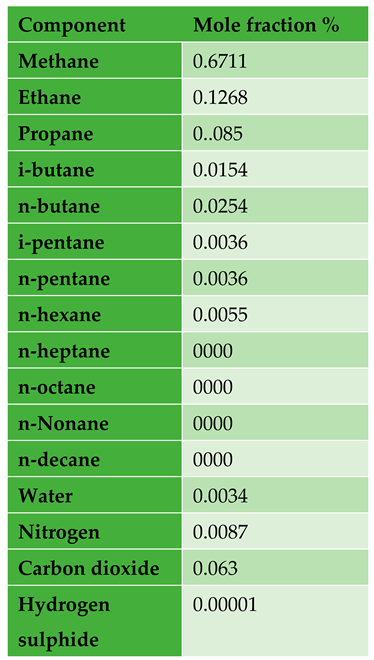
Table 3.
Stripping with nitrogen gas regeneration.
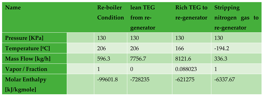
Table 4.
Regeneration using dry natural gas generated during stripping.
Disclaimer/Publisher’s Note: The statements, opinions and data contained in all publications are solely those of the individual author(s) and contributor(s) and not of MDPI and/or the editor(s). MDPI and/or the editor(s) disclaim responsibility for any injury to people or property resulting from any ideas, methods, instructions or products referred to in the content. |
© 2024 by the authors. Licensee MDPI, Basel, Switzerland. This article is an open access article distributed under the terms and conditions of the Creative Commons Attribution (CC BY) license (http://creativecommons.org/licenses/by/4.0/).
Copyright: This open access article is published under a Creative Commons CC BY 4.0 license, which permit the free download, distribution, and reuse, provided that the author and preprint are cited in any reuse.


