

Submitted:
08 January 2024
Posted:
08 January 2024
You are already at the latest version
Abstract
Interior permanent magnets motors are widely used in applications requiring high power den-sity and high efficiency due to their high torque generating capabilities. Recently, given the re-cent price fluctuations and unstable supply of rare-earth permanent magnets, alternative config-urations with reduced use of permanent magnets are being sought. Among the various candi-dates related to this, the consequent-pole type rotor structure can halve the number of perma-nent magnets used compared with conventional structures. However, in the no-load analysis, the waveform of the back electromotive force becomes asymmetric, generating a harmonic component. As a result, there is a disadvantage that the torque ripple increases. To overcome these shortcomings, we propose a novel rotor structure that applies a consequent-pole structure to an embedded permanent-magnet motor structure, wherein a number of permanent magnets are arranged in a flared structure to constitute a single polarity. In the proposed flared-structured magnet arrangement, it is possible to adjust the angle of the permanent magnet and the polar angle to mitigate the asymmetry of the back EMF waveform. The proposed struc-ture was optimized with a genetic algorithm and a prototype of the optimal model was con-structed and experimentally evaluated to verify its validity. Finally, the performance improve-ment and validity of the proposed structure were verified by comparing the analysis results of the optimal model with the experimental results.
Keywords:
Consequent-pole
; Ferrite magnet
; Flared-shape structure
; Genetic algorithm
; Interior permanent magnet motor
; Optimization
; Permanent magnets
1. Introduction
Permanent magnet (PM) brushless AC motors are widely used as power sources for vehicles and home appliances. These machines can be categorized as interior PM motors (IPM) and surface-mounted PM (SPM) motors, wherein the PMs are attached to the rotor surface. In particular, IPM motors are used in a variety of fields because they can provide a reluctance torque component in addition to the magnet torque component, resulting in an increased torque density when compared with that of SPM motors. This is structurally advantageous for high-speed operation, where it helps in the mitigation of the scattering problems of PMs [1,2]. In particular, IPM motors using rare-earth magnets with a high residual magnetic flux density, are applied to energy systems that require high power density and efficiency. However, rare-earth magnets are expensive, and their supply is unstable owing to the limited production and strict policies. Therefore, studies to find an alternative to the series of rare-earth PMs are being conducted. In particular, ferrite magnets have a low residual magnetic flux density compared with the rare-earth magnets, and extensive research is underway pertaining to the use of a ferrite magnet as a rare-earth substitute because of their low price and stable supply [3,4,5,6]. Therefore, studies on a model based on a ferrite magnet providing reluctance torque and on a model based on a consequent-pole (CP) structure to reduce the use of magnets, are being studied. The CP structure can reduce the use of PMs. Also it can be used in areas that require a high output, while having a multipole structure. In addition, it is possible to review the additional performance by changing the slot/pole combination.
The vernier permanent magnet (VPM) motor has the advantage of generating a high torque at a low speed [7,8]. However, because VPM motors require relatively large magnet usage, studies to apply the CP structure are underway. In particular, research is being conducted to improve the back electromotive force (EMF) and torque while reducing the use of PMs by mixing the toroidal-winding outer-rotor and CP structure with the VPM motor structure [9,10,11,12,13]. Further, to improve the torque characteristics in flux weakening operation, research is also being conducted to apply the CP motor (CPM) structure to the rotor structure [14,15,16]. There are also studies that have applied the CP PMs and Halbach PM arrays to a linear PM vernier machine [17].
The switched reluctance motor (SRM) has a mechanically robust structure and is low-priced due to the absence of PMs. However, it has the disadvantage of having a relatively low efficiency and high noise and vibration compared with the PM motors. To increase the efficiency of SRMs, research is being conducted to apply the CP structure to the SRM structure, securing a wide speed area and increasing the torque density when a sine wave current is applied and reducing the ripple (DC current application) and magnetic usage [18,19].
In addition, a study is also underway to apply the CP structure to the transverse-flux motor structure. In particular, the CP structure is applied to the flux-reversal PM motor to reduce the PM usage and torque ripple [20]. The CP structure which is widely used in various fields is basically arranged with the same polarity and the opposite polarity is composed of iron cores. Therefore, it is difficult to design, and further studies are required to improve the asymmetric waveforms of the EMF and the structural noise vibrations.
In this study, we propose a novel CP rotor structure of the IPM model used in automotive compressor systems. The rotor structure, wherein the CP-type PMs are arranged in a flared-structure, is advantageous for the concentration of magnetic flux, thereby improving the power density and reducing the torque ripple. This, in turn, is advantageous for the noise and vibration [21,22,23]. Therefore, the proposed flared CPM (FCPM) can halve the number of magnets required by applying the CP structure to the flared IPM rotor structure. In addition, to improve the performance, the angle, thickness, and pole angle of the CP-type magnet were set as variables, and optimized.
The feasibility of the proposed structure was evaluated using finite element analysis, and the performance of the basic model and the proposed optimized model was compared. In addition, a prototype of the proposed model was constructed and experimentally evaluated. Finally, the performance improvement and validity of the proposed structure were confirmed by comparing the analysis results of the proposed model with the experimental results.
2. Air conditioner system and compressor motor of the electric vehicle
2.1. Main circuit system of the electric vehicle
Figure 1 shows the main circuit system of an electric vehicle. The main circuit systems of electric cars can be broadly categorized into electronic control systems, electric drive systems, air conditioner systems, and battery management systems. The vehicle air conditioning system functions to heat, ventilate, and cool the vehicle for the comfort of the driver and occupants by controlling the internal environment of the vehicle efficiently. The key function of the vehicle air conditioning system is to provide a fresh air into the vehicle for ventilation. The objective of the vapor compression system is to cool the air that is introduced into the vehicle in the shortest possible time.
In addition, the compressor system used in the vehicle air conditioning system performs an important role for reducing energy consumption and improving efficiency. Therefore, most compressor systems use IPM-type motors. Figure 2 shows the main components of the vehicle compressor system. The original motor applied to the compressor system was an IPM motor with a ferrite magnet.
2.2. Standard flared IPM motor of compressor
Figure 3 shows the structure of the IPM model with a flared pole structure. The pole of flared rotor structure comprises of several ferrite PMs. The advantage of the flared shape is that it can increase the power density by securing more magnetic usage within the limited rotor radius, and structurally, it is advantageous for magnetic flux concentration. Also, in Figure 3, A, B, and C indicate phases, and (+) and (-) indicate input and output of phases. Table 1 shows the materials and specifications of a standard flared-shaped IPM model.
2.3. Proposed flared-type CP IPM motor
Figure 4 shows the basic model of the proposed FCPM in this study, in which the magnet that constitutes the S pole are removed from the standard flared-shaped model. An electric steel plate is placed at the position of the removed S pole.
In a conventional PM rotor structure, the magnetizing directions of the magnets are alternately arranged such that the N and S poles are alternately present. However, the consequent-pole type rotor structure removes the permanent magnets constituting the S pole, and makes the N and S poles alternately formed in the rotor by using the magnetic flux lines of the permanent magnets forming the N pole. Therefore, there is an advantage of reducing the usage of permanent magnets by half. However, the CP-type rotor structure has the disadvantage of increasing the torque ripple because of the asymmetry of the back-EMF.
Figure 5 shows the two-dimensional (2D) finite element method (FEM) analysis results of the basic FCPM model under the no-load condition and Table 2 shows the comparison results of the no-load analysis of the standard flared-type IPM model with that of the basic FCPM model. The basic FCPM model has the advantage of halving the number of magnets used, compared with the standard flared-shaped IPM model. However, as shown in Figure 5, the back-EMF waveform is asymmetrical, and this significantly increases the total harmonic distortion (THD) of the back-EMF to 29.5 %.
In addition, a 37.7 % reduction can be observed in the back-EMF. Therefore, owing to a decrease in the back-EMF, an increase in the current and a decrease in the efficiency at the rated load are expected. However, due to the decrease in the amount of PMs, the cogging torque ripple decreases by 36.2 %, and the torque ripple is also expected to decrease at the rated load.
The flared-structured rotor comprises one polarity with four magnets so it conveniently enables controlling the polar angle that conveys a single polarity. Therefore, by optimizing the polar angle to form one polarity and the angle of individual PMs, the waveform of the back-EMF can be made symmetrical. Accordingly, it is possible to minimize the THD and performance reduction. Therefore, in this study, we propose the shape of the basic FCPM model and optimize it. The purpose of this study is to improve the performance while taking advantage of the CP model, thereby reducing the use of PMs. As design variables, the polar angle formed by the PM and the angles of the individual PMs were set as variables to proceed with the design optimization. Through this, an optimal model with a high torque performance and low torque ripple was designed to reduce the use of PMs.
3. Optimal design of the FCPM model
Figure 6 shows the optimization process. For optimization, first, the design of the experiment (DOE) should be considered. The DOE is essentially conducted using the Latin hypercube sampling (LHS) technique that has no overlap between the design variables and is easy to implement. In addition, a kriging modeling technique with multiple design variables and a strong nonlinearity is used to set the objective function.
Also, a genetic algorithm (GA) was used as the optimization algorithm. The GA efficiently converges to the optimal design value while searching the entire range of the optimization design variables and has a low error rate and high reliability [24]. GA first distribute a plurality of design points in the initial design phase, and thereafter consider the degree of violation of the objective function value and constraints. This makes it suitable for each design point. GA can search for a better design point because the higher the suitability of the individual point, the higher is the probability of participating in the mating and variant processes. Through this repetitive process, the GA converge to a better design point.
The characteristic analysis for each sample case is performed through the 2D-FEM and the electromagnetic field analysis program used is JMAG Designer v17.1.
3.1. Design variables, objective functions and constraints (step I)
First, to improve the performance of the basic FCPM model, design variables that can change the asymmetric waveform of the back-EMF into a symmetric structure are selected in the optimal design. There are various variables, but finally the angle and polar angle of the PM were set as variables. In addition, to take advantage of the CP-type structure, the volume of one CP-type PM was fixed. As the thickness of the PM decreases, it becomes difficult to manufacture the permanent magnet. So, the thickness of the PM is fixed at 3 mm. Figure 7 shows the design parameters for optimization. As shown in Figure 7, the design variable x1 refers to the magnet angle, x2 refers to the polar angle, and Table 3 shows the range of design parameters.
Table 4 lists the dimensional constraints for determining the magnet angle (x1). As shown in Table 4, R1 represents the inner radius of each magnet, and R2 represents the outer radius. Although the inner and outer radius were changed, the weight of each magnet was the same, and the thickness was limited to 3 mm.
For optimization, the objective function is determined as the maximum of the back-EMF, as well as the minimum THD of the back-EMF and cogging torque. In addition, the magnitude (RMS value), THD of the back-EMF, and cogging torque were set as performance constraints. The objective function and constraints are as follows:
- 1) Objective function:
- Maximize:
- - y1 (magnitude of back-EMF)
- Minimize:
- - y2 (total harmonic distortion (THD)), y3 (peak to peak value of cogging torque)
- 2) Constraint:
- - back-EMF (RMS) > 29 Vrms, THD of back-EMF < 10 %, cogging torque ripple < 0.13 Nm
3.2. LHS (step II)
To design the optimal shape of the rotor structure, the design variables were selected and the sampling range of the selected design variables was determined using the experimental design method. In the optimal design process, the LHS technique was used to determine the experimental points. In the LHS technique, the experimental points are represented as a matrix of n rows and k columns, and each row is arranged as an experimental point, where n is the number of levels and k is the number of design variables. The characteristic of the LHS sampling technique is that it is easy to implement without causing any overlap between the experimental points depending on the design level at the time of model construction [25,26,27]. The 2D FEM is used to calculate the characteristics of the model based on the design variables for each experimental point. Table 5 shows the analysis results corresponding to each DOE case.
The analysis result values shown in Table 5 represent the cogging torque, back-EMF, and THD according to the DOE model. The kriging model was used to obtain a more accurate approximation model based on the nonlinear analysis results. The GA is applied to find the optimal solution.
3.3. Optimal design of basic FCPM model using GA (step III)
The GA was used to determine the optimal design point that satisfies the objective function and constraints. Figure 8 shows the convergence process for the design variables. It can be seen that the magnet angle x1 and the polar angle x2 converge to 58.3 degrees and 39.4 degrees, respectively.
Figure 9 shows the convergence process for the objective functions and each objective function converge to the optimal point. The number of convergences was set to a total of 200 in consideration of the design time.
Figure 10 shows the change in the shape of the core through optimization and the optimal points of the design variables calculated through the optimization process are shown in Table 6. As a result, the magnetic angle of the individual magnets reduced, and the pole angles widened. Therefore, as shown in Figure 10, the basic model partially has a very high magnetic flux density distribution, but it can be confirmed that the optimal model has a wide distribution of magnetic flux density. Through this, it can be confirmed that the asymmetric back-EMF waveform has been changed to a symmetric structure.
Figure 11 shows a comparison of the analysis under no-load conditions between the basic and optimal FCPM models. As shown in Figure 11, through optimization, the back-EMF waveform of the optimized model was improved, and through the analysis of the harmonic order, it can be confirmed that the THD also improved. The cogging torque due to the combination of the pole slots must generate a total of six ripples when rotating one round electrically. However, the basic model did not show periodicity owing to the influence of the asymmetric back-EMF. In the case of the optimal model, the periodicity of the cogging torque appears, and it can be seen that the magnitude of the ripple is also reduced.
Table 7 shows a comparison of the optimization results under the no-load condition. Through optimization, it can be seen that the Back-EMF is increased by 14.5 %, and the THD of Back-EMF and cogging torque are reduced by 38.3 % and 25.4%, respectively.
Figure 12 shows the torque waveform at the rated load and the analysis results of the optimal model using a 2D-FEM are shown in Table 8, to compare with the characteristics of the basic FCPM model. Through optimization, it can be seen that the torque ripple is reduced by 73.8 %, and the efficiency is increased by 2.7 %.
4. Verification through prototyping and experimentation
4.1. Prototype of optimal FCPM model
To verify the performance improvement of the optimal FCPM model, a prototype was produced and an experiment was conducted. Figure 13 shows the prototype of the proposed, optimal FCPM model. Figure 13(a) shows the stator assembly and Figure 13(b) shows the rotor assembly. Also Figure 13(c) shows the PM arrangement inside the rotor assembly. As shown in Figure 13(c), the polarity inside the rotor is composed of a CP-type (four N poles).
Figure 14 shows a magnified view of the rotor assembly. As shown in the figure, a guide made of a non-magnetic material is inserted inside. This prevents the magnetic flux of the permanent magnet from circulating inside the rotor. The end-plate is assembled on the upper and lower parts of the rotor and combines the structure of the rotor. it prevents the permanent magnet from scattering at high speed. Figure 15 shows the surface gauss value of the optimal FCPM rotor assembly. As shown in Figure 15, it can be seen that 8 poles are formed inside the rotor.
4.2. Experimental results of optimal FCPM model
A load test was conducted for the prototype at the rated load. Figure 16 shows the comparison of the back-EMF waveform with analysis result and experimental result of the prototype. As shown in Figure 16, a waveform similar to the analysis result was generated.
Figure 17 shows the torque waveform at the rated load and Table 9 shows a comparison of the analysis result and experimental results for the FCPM prototype model.
As shown in Table 9, the experimental results of the optimal FCPM model are similar to the analysis results. This confirms the performance improvement of the proposed model. In particular, the use of PMs was halved, compared with the basic FCPM model, the efficiency of the optimal FCPM prototype was improved by 2.6 % and the torque ripple was significantly reduced by 74.9%. The CPM structure has the advantage of reducing the amount of magnet used. However, due to the asymmetry of Back-EMF, various problems can occur. In this paper, the FCPM structure is proposed and the performance is improved through optimization, and in particular, it was confirmed that the THD and torque ripple reduction were improved.
5. Conclusions
In this study, a novel consequent-pole rotor structure is proposed that applies the flared CP structure to the IPM model structure. In the flared IPM motor structure, a number of PMs are arranged inside the rotor in a flared structure to comprise a single polarity. This is advantageous for concentrating the magnetic flux and controlling the angle of the magnetic pole. Therefore, a novel flared CP structure is proposed by utilizing the characteristics of the flared-structured rotor and the magnitude reduction and asymmetry limitations of the back-EMF are improved through optimization using GA. In particular, compared with the analysis result of basic FCPM model, the analysis result of optimal FCPM model has increased the magnitude of the back-EMF by 14.5 % and the asymmetric back-EMF waveform of the optimal FCPM model is improved symmetrically. Therefore, the THD of the back-EMF is also reduced by 38.3 %. In addition, at a rated load, the torque ripple is also reduced by 73.8 % and the efficiency improved by 2.7 %.
To confirm the validity of the optimization result, a prototype of the optimal FCPM model was constructed and evaluated experimentally. Finally, as a result of comparing the analysis results of the optimal model with the experimental results, it was possible to improve the performance of the proposed FCPM model and verify the validity of the optimization results. In the future, we will conduct an actual SET performance test using the prototype produced in this paper.
Author Contributions
Conceptualization, K. Y. Y. and Y. M. Y.; methodology, K. Y. Y. and Y. M. Y.; software, K. Y. Y.; validation, K. Y. Y. and Y. M. Y.; writing—original draft preparation, K. Y. Y.; writing—review and editing, K. Y. H. and Y. M. Y.; and funding acquisition, K. Y. Y.; All authors have read and agreed to the published version of the manuscript.
Funding
This study was supported by a 2023 research fund from the Honam University; This results was also supported by "Regional Innovation Strategy (RIS)" through the National Research Foundation of Korea(NRF) funded by the Ministry of Education(MOE)(2021RIS-002).
Institutional Review Board Statement
Not applicable.
Informed Consent Statement
Not applicable.
Data Availability Statement
The data presented in this study are available upon request from the corresponding author.
Acknowledgments
We would like to thank Editage for the English language editing.
Conflicts of Interest
The authors declare no conflict of interest.
References
- Ling Fang, J. W. Jung, J. P. Hong, J. H. Lee, “Study on High-Efficiency Performance in Interior Permanent-Magnet Synchronous Motor with Double-layer PM Design,” IEEE Trans. Magn., vol. 44, no. 11, Nov. 2008, pp. 4393-4396. [CrossRef]
- Rukmi Dutta, M. F. Rahman, “Design and Analysis of an Interior Permanent Magnet(IPM) Machine with Very Wide Constant Power Operation Range,” IEEE Trans. Energy Convers., vol. 23, no. 1, Mar. 2008, pp. 25-33. [CrossRef]
- H. J. Kim, D. Y. Kim, J. P. Hong, “Structure of Concentrated-Flux-Type Interior Permanent-Magnet Synchronous Motors Using Ferrite Permanent Magnets,” IEEE Trans. Magn., vol. 50, no. 11, Nov. 2014, Art. no. 8206704. [CrossRef]
- M. M. Rahman, K. Kim, and J. Hur, “Design and optimization of neodymium-free SPOKE-type motor with segmented wing-shaped PM,” IEEE Trans. Magn., vol. 50, no. 2, Feb. 2014, Art. no. 7021404. [CrossRef]
- Chiba.K, Takemoto.M, Ogasawara.S, Woo-Gyong Yim, “Ferrite-magnet spoke-type IPMSM with w-shaped magnet placement,” IECON, Nov. 2013, pp. 2869-2874.
- W. Zhao, T. A. Lipo, and B. I. Kwon, “Comparative study on novel dual stator radial flux and axial flux permanent magnet motors with ferrite magnets for traction application,” IEEE Trans. Magn., vol. 50, no. 11, Nov. 2014, Art. no. 8104404. [CrossRef]
- Toba and T. A. Lipo, “Generic torque-maximizing design methodology of surface permanent-magnet vernier machine,” IEEE Trans. Ind. Appl., vol. 36, no. 6, Nov./Dec. 2000, pp. 1539–1546. [CrossRef]
- S. Chung et al., “A novel design of modular three-phase permanent magnet vernier machine with consequent pole rotor,” IEEE Trans. Magn., vol. 47, no. 10, Oct. 2011, pp. 4215–4218.
- S. Niu, S. Ho, W. Fu, and L. Wang, “Quantitative comparison of novel vernier permanent magnet machines,” IEEE Trans. Magn., vol. 46, no. 6, Jun. 2010, pp. 2032–2035. [CrossRef]
- J. Yang et al., “Quantitative comparison for fractional-slot concentrated-winding configurations of permanent-magnet vernier machines,” IEEE Trans. Magn., vol. 49, no. 7, Jul. 2013, pp. 3826–3829. [CrossRef]
- D. Li, R. Qu, and T. Lipo, “High power factor Vernier permanent magnet machines,” IEEE Trans. Ind. Appl., vol. 50, no. 6, Nov./Dec. 2014, pp. 3664–3674. [CrossRef]
- S. Chung et al., “A novel design of modular three-phase permanent magnet Vernier machine with consequent pole rotor,” IEEE Trans. Magn., vol. 47, no. 10, Oct. 2011, pp. 4215–4218. [CrossRef]
- Dawei Li, Ronghai Qu, Jian Li, Wei Xu, “Consequent-Pole Toroidal-Winding Outer-Rotor Vernier Permanent-Magnet Machines,” IEEE Trans. Ind. Appl., vol. 51, no. 6, Nov./Dec. 2015, pp. 4470-4481. [CrossRef]
- Haitao Wang, Shuhua Fang, Hui Yang, Heyun Lin, Dong Wang, Yibo Li and Chenxiao Jiu, “A Novel Consequent-Pole Hybrid Excited Vernier Machine,” IEEE Trans. Magn., vol. 53, no. 11, Nov. 2017, Art. no. 8112304. [CrossRef]
- Y. Amara, L. Vido, M. Gabsi, E. Hoang, A. Hamid Ben Ahmed, and M. Lecrivain, “Hybrid excitation synchronous machines: Energy-efficient solution for vehicles propulsion,” 2006 IEEE Vehicle Power and Propulsion Conference, Sept. 2006.
- H. Hua, and Z. Q. Zhu. “Novel parallel hybrid excited machines with separate stators,” IEEE Trans. Energy Convers., vol. 31, no. 3, Sep. 2016, pp. 1212-1220. [CrossRef]
- Chaojie Shi, Ronghai Qu, Dawei Li, He Zhang, Yuting Gao, and Yongsheng Huo, “A Novel Linear Permanent Magnet Vernier Machine with Consequent-Pole Permanent Magnets and Halbach Permanent Magnet Arrays,” IEEE Trans. Magn., vol. 53, no. 11, Nov. 2017, Art. no. 2501404. [CrossRef]
- Shaofeng Jia, Ronghai Qu, Jian Li, Dawei Li, and Wubin Kong, “A Stator-PM Consequent-Pole Vernier Machine With Hybrid Excitation and DC-Biased Sinusoidal Current,” IEEE Trans. Magn., vol. 53, no. 6, Jun. 2017, Art. no. 8105404. [CrossRef]
- Yuting Gao, Ronghai Qu, Dawei Li, Jian Li, and Guopeng Zhou,” Consequent-Pole Flux-Reversal Permanent-Magnet Machine for Electric Vehicle Propulsion,” IEEE Trans. Appl. Superc., vol. 26, no. 4, Jun. 2016, Art. no. 5200105. [CrossRef]
- Xing Zhao, Shuangxia Niu, “Design of a Novel Consequent-Pole Transverse-Flux Machine with Improved Permanent Magnet Utilization,” IEEE Trans. Magn., vol. 53, no. 11, Nov. 2017, Art. no. 8110405. [CrossRef]
- K. Yoon, J. Lee, B. Kwon, “Characteristics of new interior permanent magnet motor using flared-shape arrangement of ferrite magnets” Int. J. Applied Electromagnetics and Mechanics, vol. 52, no. 1-2, pp.591-597, Dec. 2016.
- K. Yoon, B. Kwon., “Optimal Design of a New Interior Permanent Magnet Model Using a Flared-Shape Arrangement of Ferrite Magnets” IEEE Trans. Magn., vol. 52, no. 7, Jul. 2016, Art. no. 8106504. [CrossRef]
- K. Yoon, S. Baek, “Performance Improvement of Concentrated-flux Type IPM Motors with Flared-shape Magnet Arrangement,” Appl. Sci., vol. 10, no. 17, Sep. 2020, pp. 1~15.
- K. J. Han, H. S. Cho, D. H. Cho and H. K. Jung, “Optimal core shape design for cogging torque reduction of brushless DC motor using genetic algorithm” IEEE Trans. Magn., vol. 36, no. 4, Jul. 2000, pp.1927-1931. [CrossRef]
- Kent R. Davey, et al., “Latin Hypercube Sampling and Pattern Search in Magnetic Field Optimization Problems”, IEEE Trans. Magn., vol. 44, no. 6, Jun. 2008, pp. 974-977. [CrossRef]
- Bilicz, S., “Kriging for Eddy-Current Testing Problems”, IEEE Trans. Magn., vol. 46, no. 8, Aug. 2010, pp. 3165-3168. [CrossRef]
- L. Lebensztajn, et al., “Kriging: A Useful Tool for Electromagnetic Device Optimization”, IEEE Trans. Magn., vol. 40, no. 2, Mar. 2004, pp. 1196-1199. [CrossRef]
Figure 1.
Main circuit system of an electric vehicle.
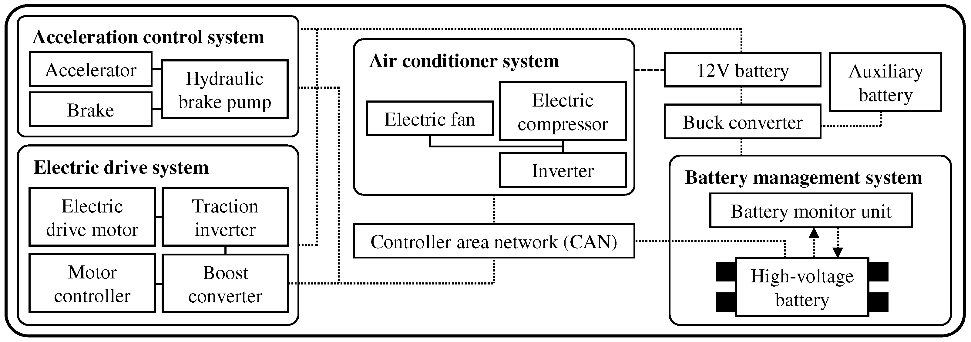
Figure 2.
The main structure of the vehicle compressor system.
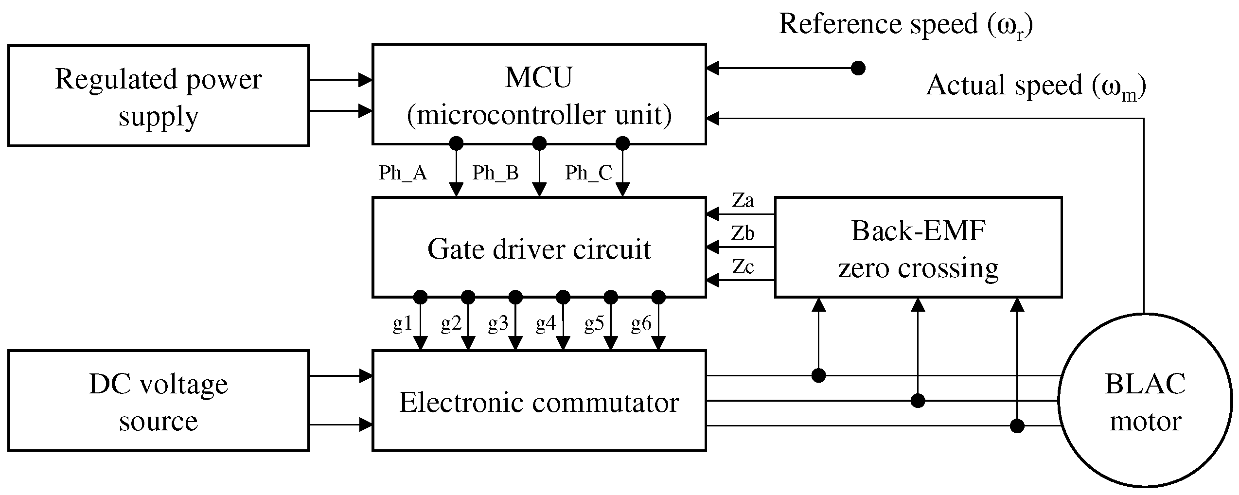
Figure 3.
Structure of flared-shaped IPM motor (1/4 model).
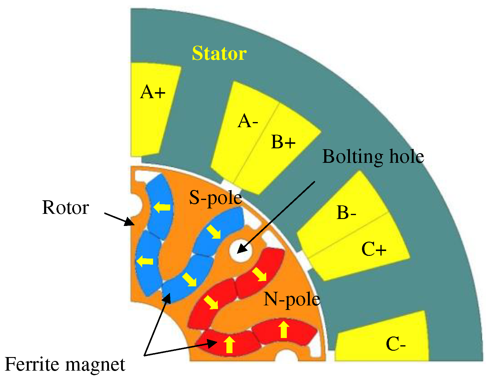
Figure 4.
Basic model of flared-type CP motor (1/4 model).
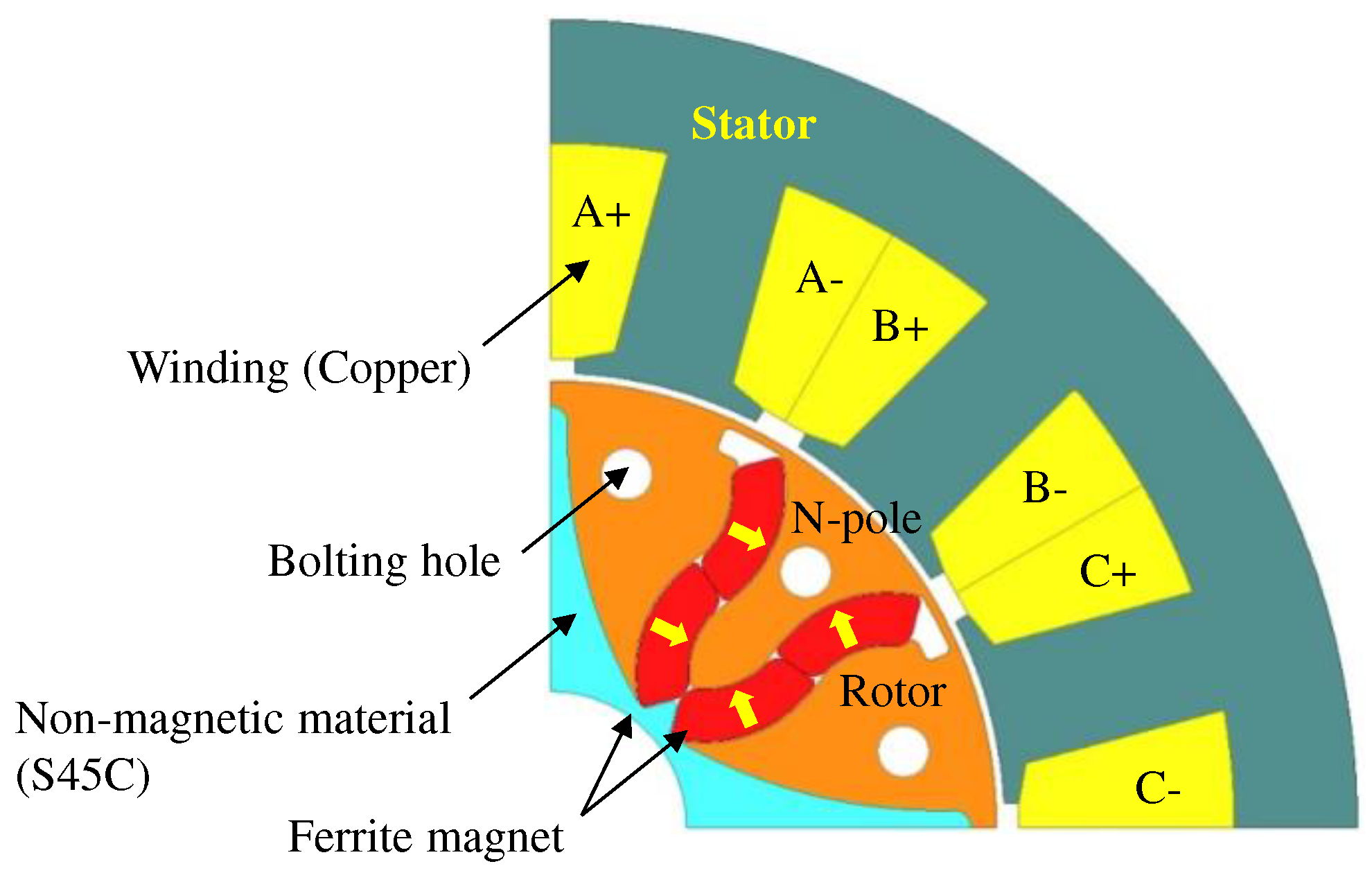
Figure 5.
Analysis results of no-load conditions (7,500 [rpm]): (a) back-EMF, (b) cogging torque.
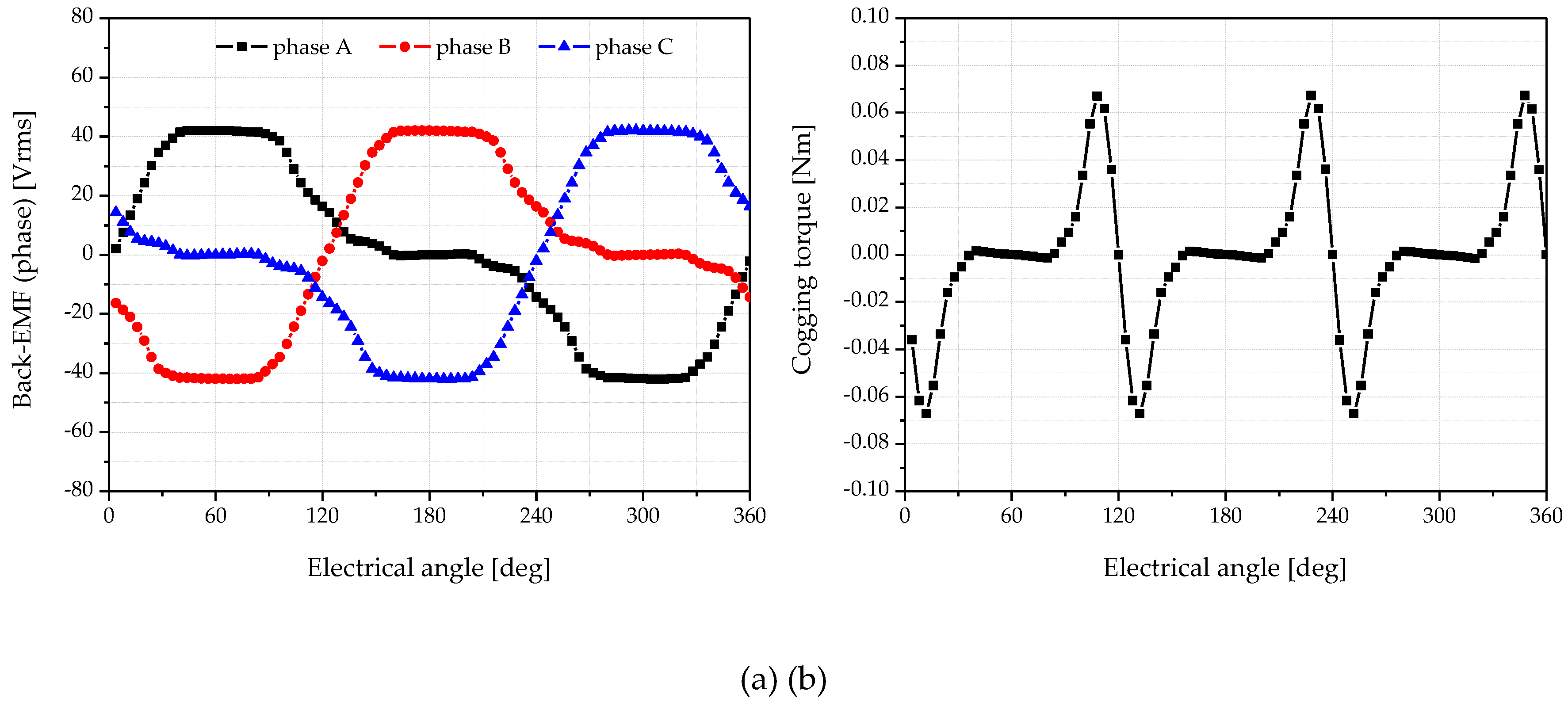
Figure 6.
Optimal design process.
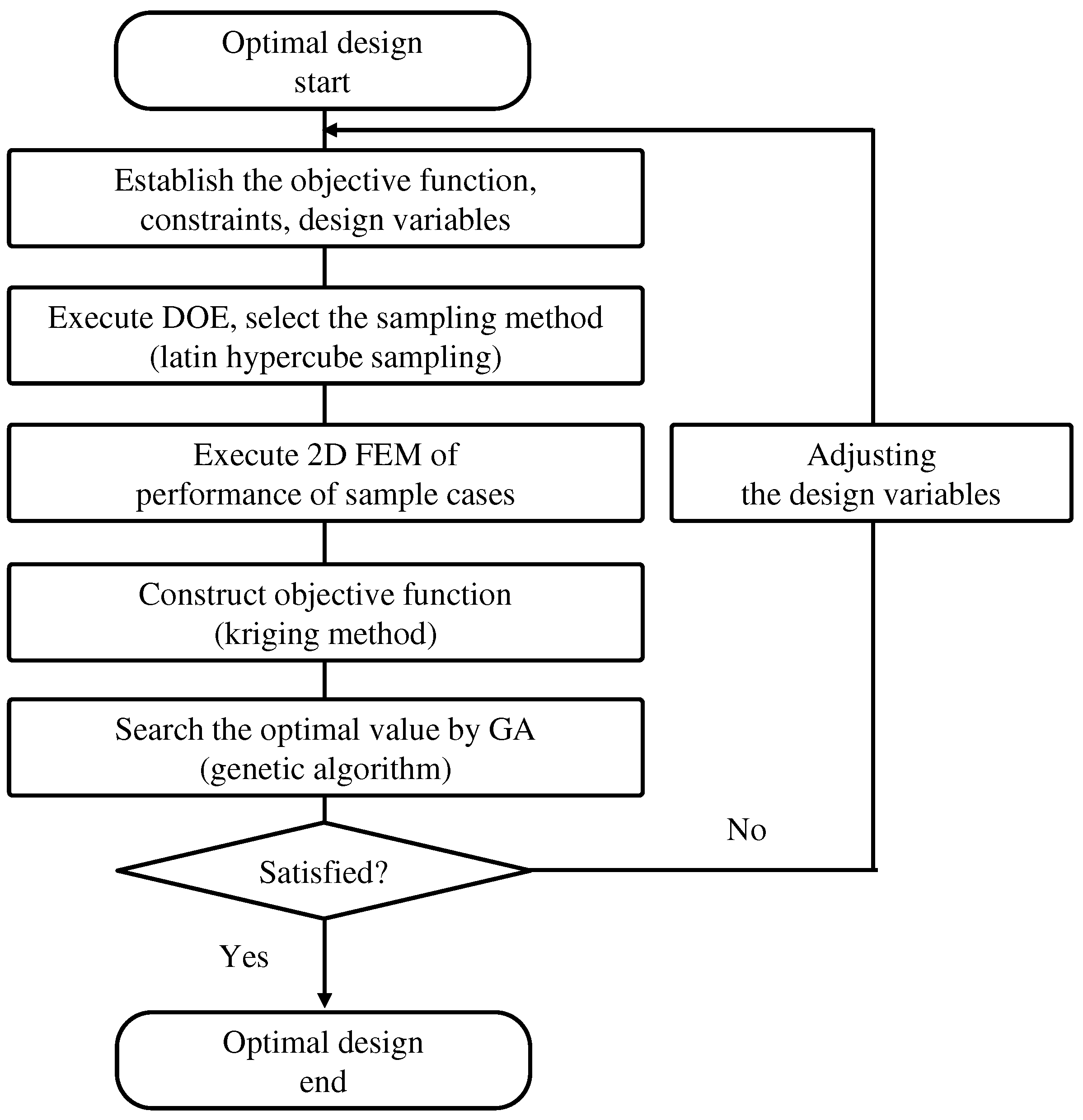
Figure 7.
Design variables of basic FCPM model.
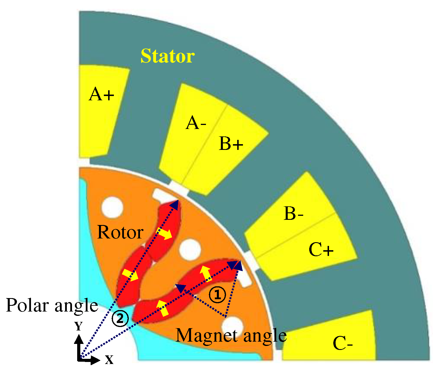
Figure 8.
Convergence results of the design variables: (a) magnet angle, (b) polar angle.
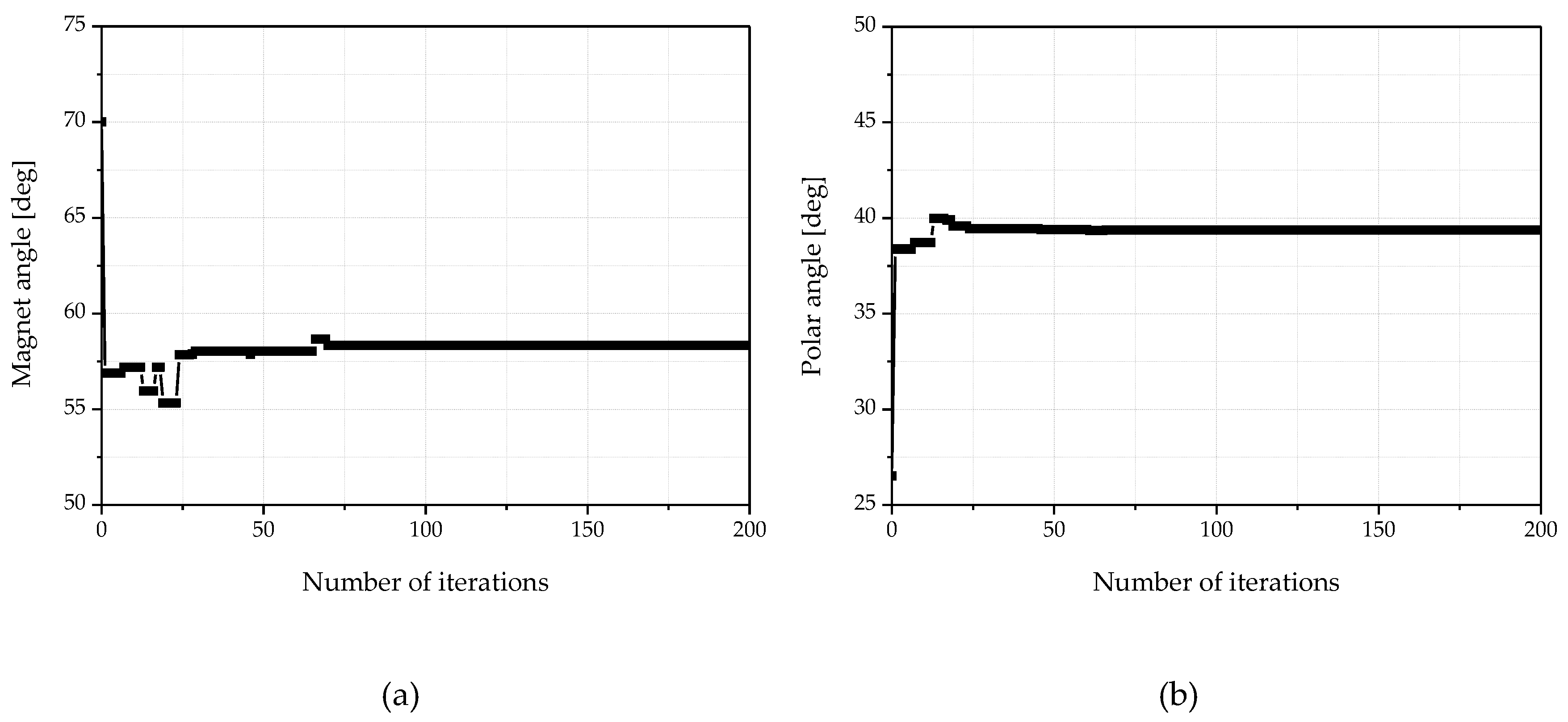
Figure 9.
Convergence results of the objective function: (a) y1(magnitude of back-EMF), (b) y2(total harmonic distortion (THD)), (c) y3(peak to peak value of cogging torque).
Figure 9.
Convergence results of the objective function: (a) y1(magnitude of back-EMF), (b) y2(total harmonic distortion (THD)), (c) y3(peak to peak value of cogging torque).
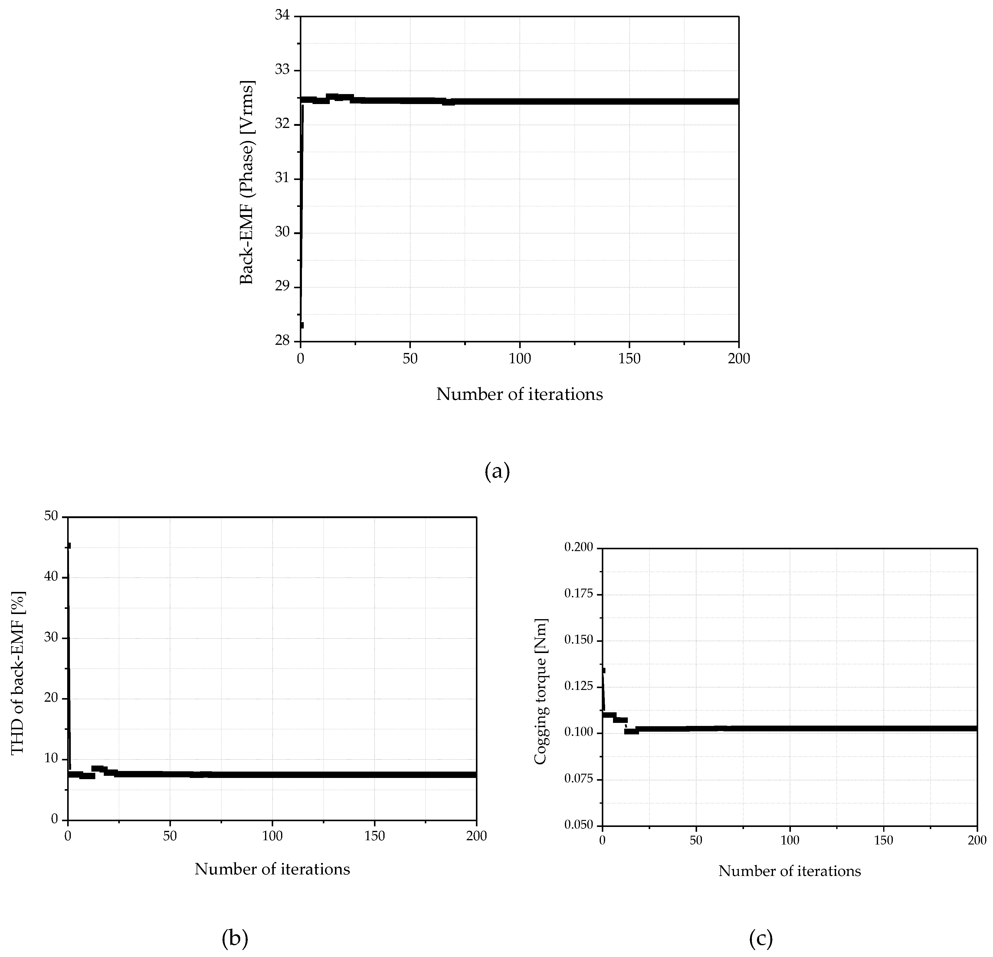
Figure 10.
Comparison of rotor assembly shape and flux density under no-load condition: (a) basic FCPM model and optimal FCPM model (1/4 model), (b) flux density under no-load condition.
Figure 10.
Comparison of rotor assembly shape and flux density under no-load condition: (a) basic FCPM model and optimal FCPM model (1/4 model), (b) flux density under no-load condition.
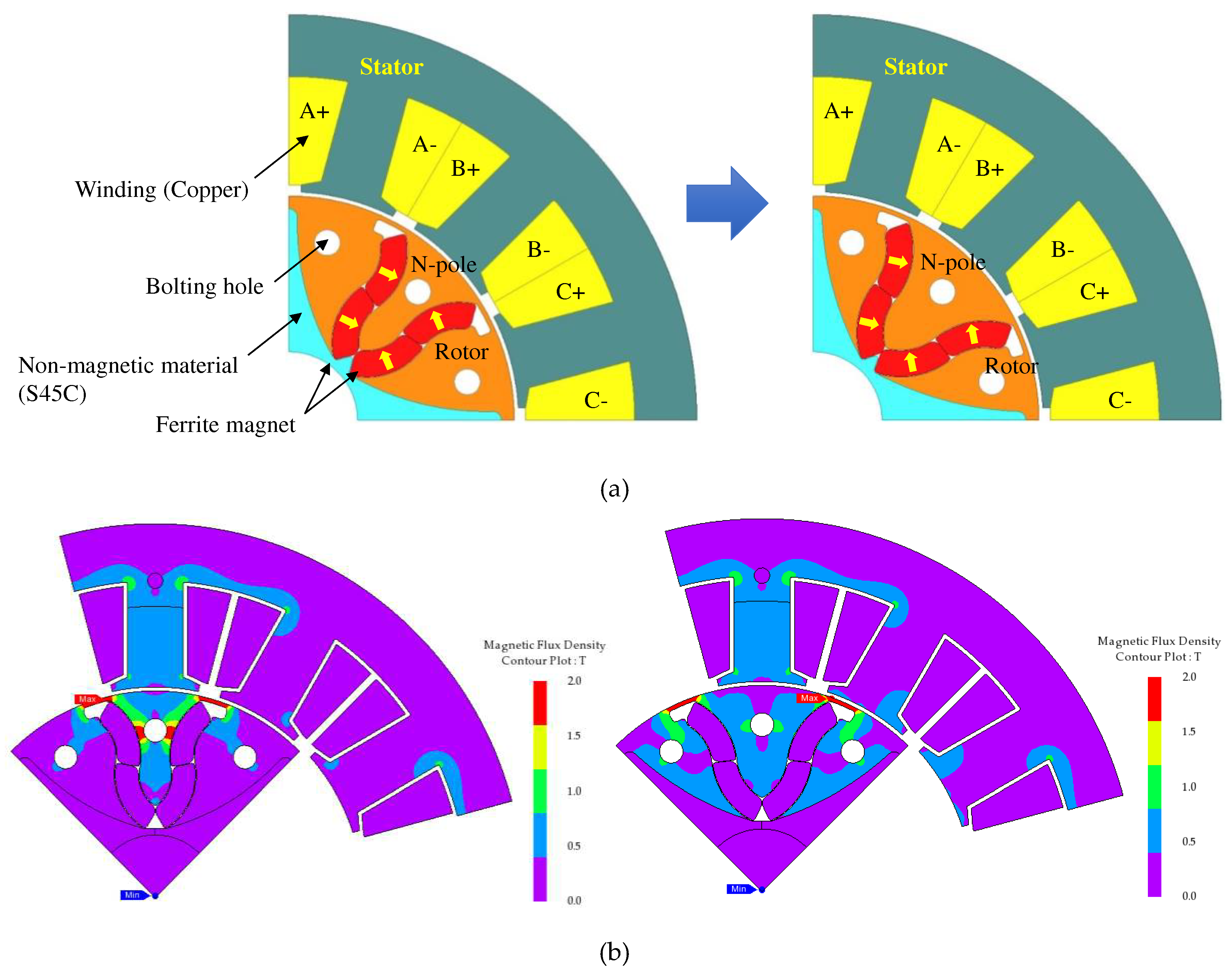
Figure 11.
No-load analysis results after optimization: (a) back-EMF, (b) total harmonic order, (c) cogging torque.
Figure 11.
No-load analysis results after optimization: (a) back-EMF, (b) total harmonic order, (c) cogging torque.
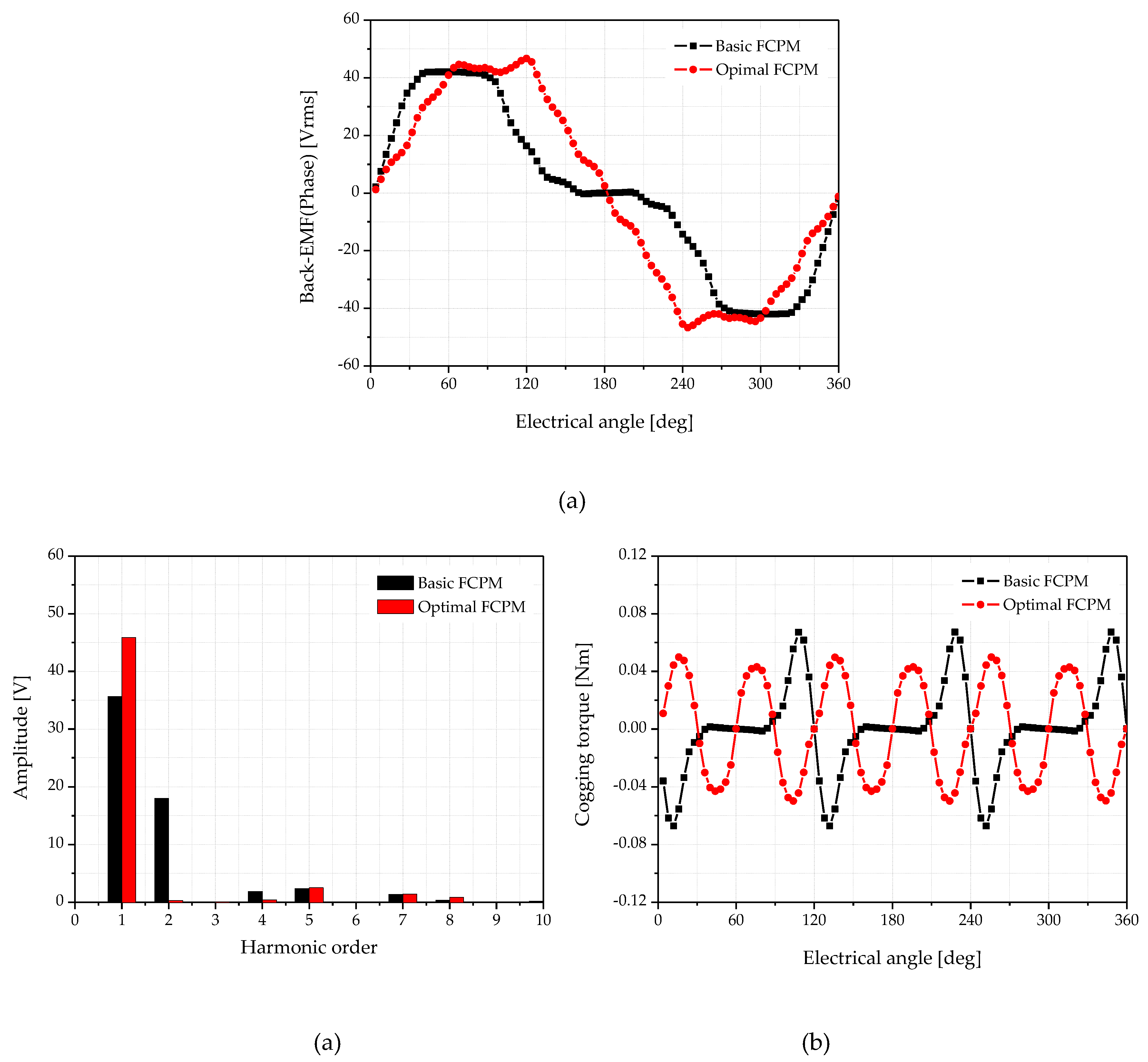
Figure 12.
Rated load analysis result after optimization: (a) rated torque waveforms, (b) flux density of basic model, (c) flux density of optimal model.
Figure 12.
Rated load analysis result after optimization: (a) rated torque waveforms, (b) flux density of basic model, (c) flux density of optimal model.
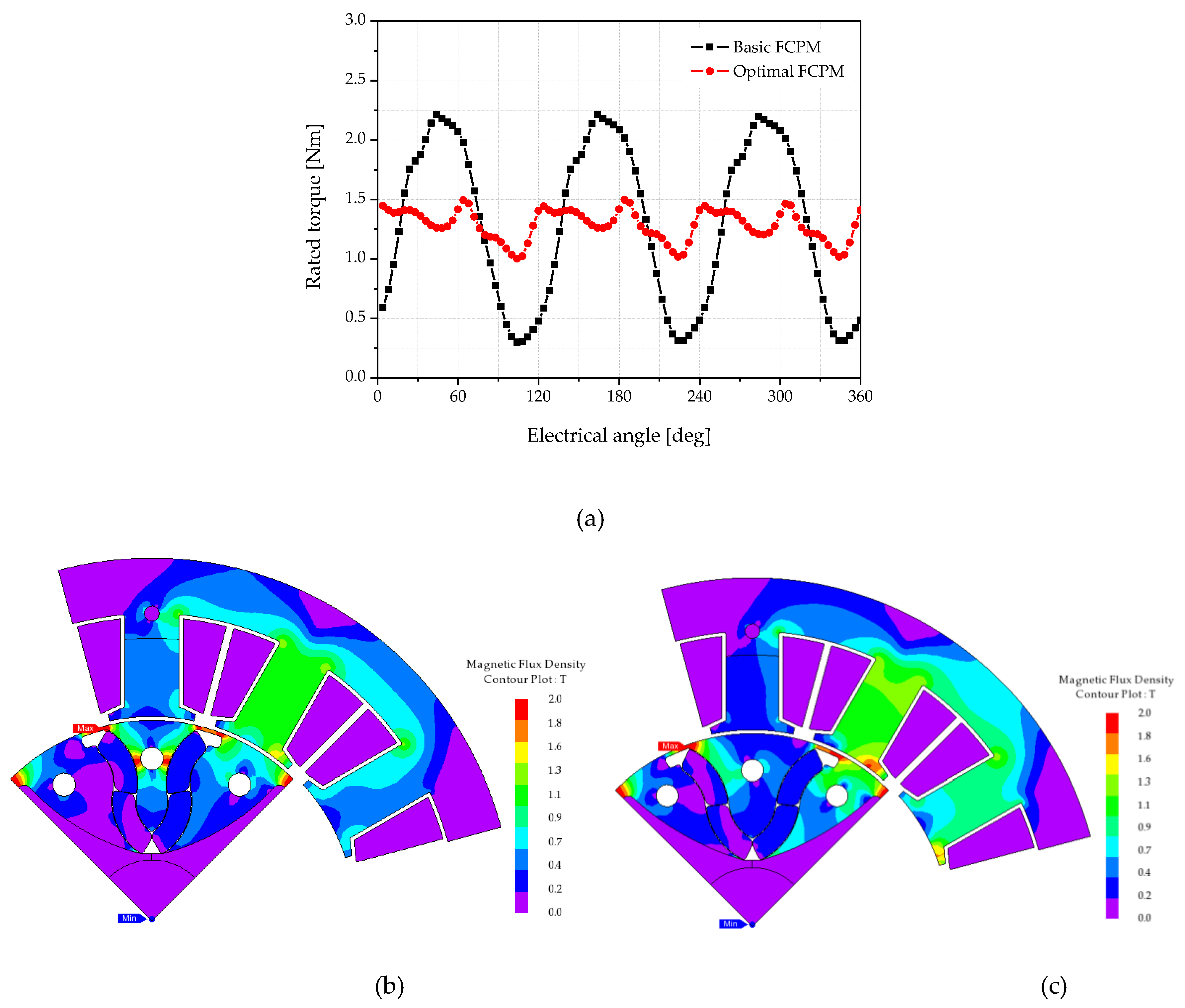
Figure 13.
Prototype of the optimal FCPM model: (a) stator assembly, (b) rotor assembly, (c) the PM arrangement inside the rotor assembly.
Figure 13.
Prototype of the optimal FCPM model: (a) stator assembly, (b) rotor assembly, (c) the PM arrangement inside the rotor assembly.
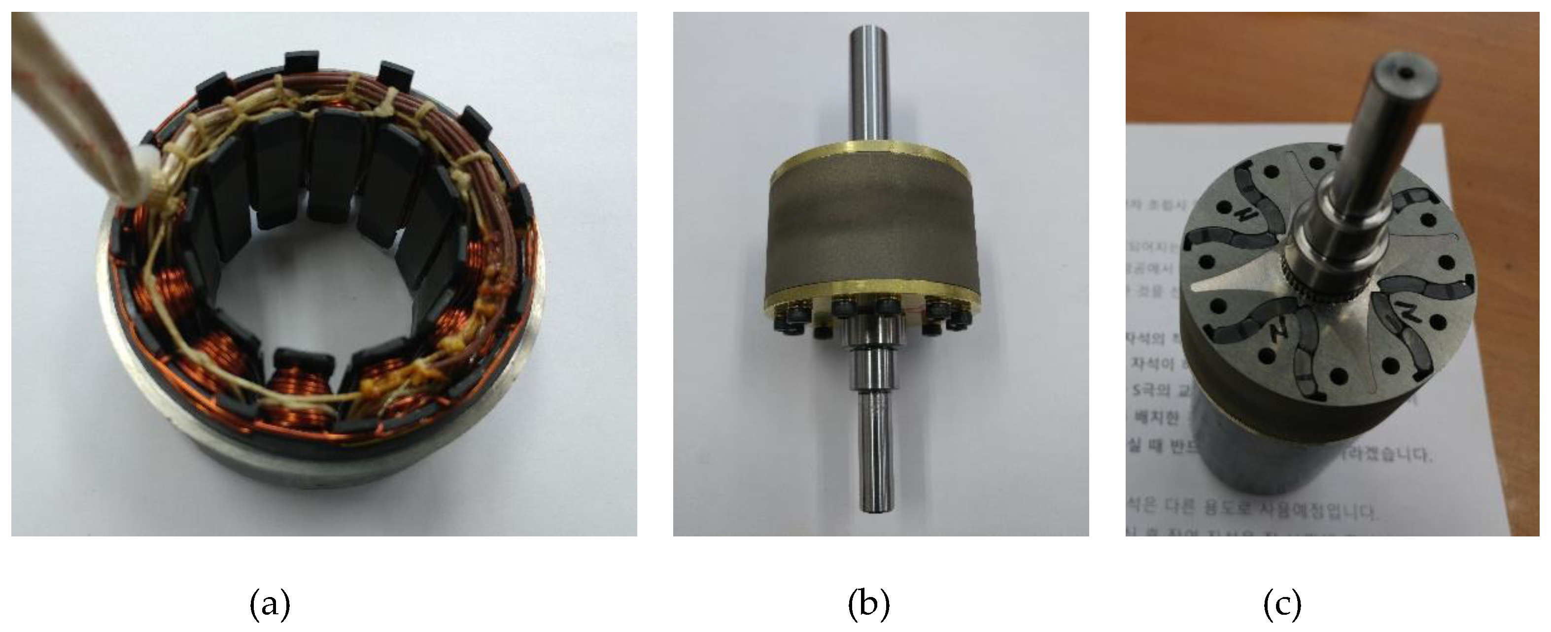
Figure 14.
Rotor Assembly of the prototype.
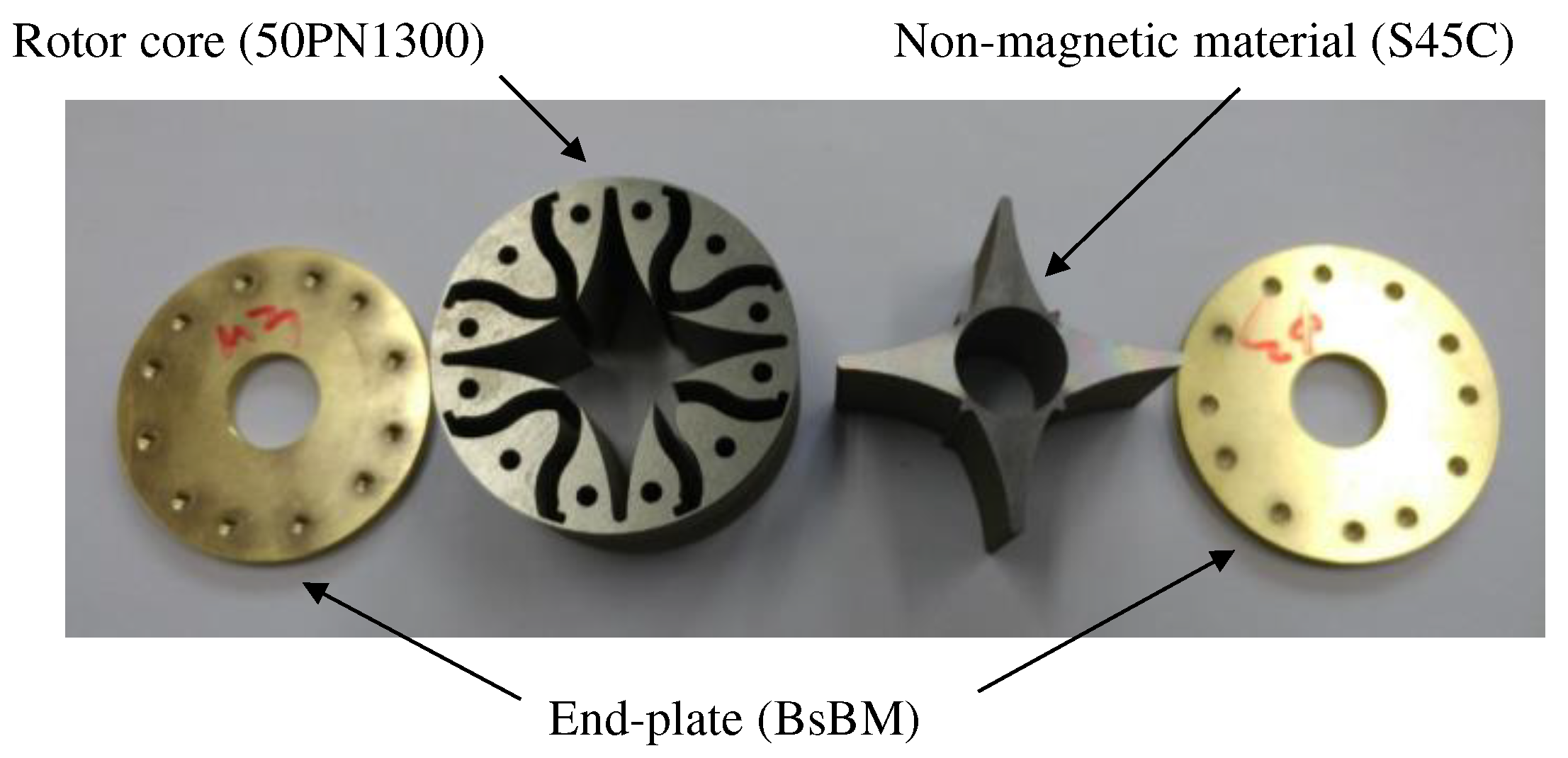
Figure 15.
Rotor Assembly of the prototype.
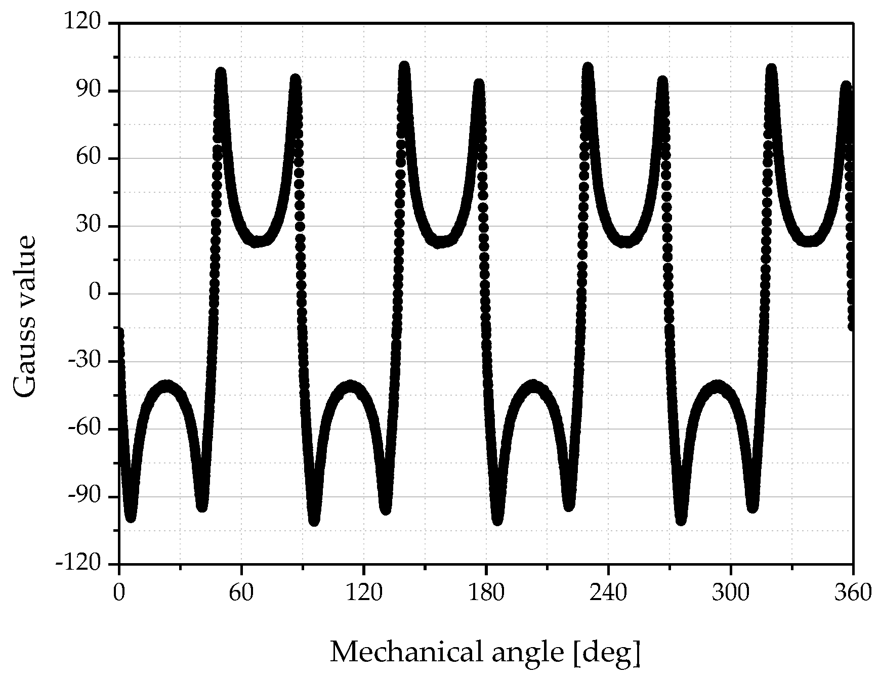
Figure 16.
Comparison of Back-EMF waveform for optimal model (at 900 rpm).
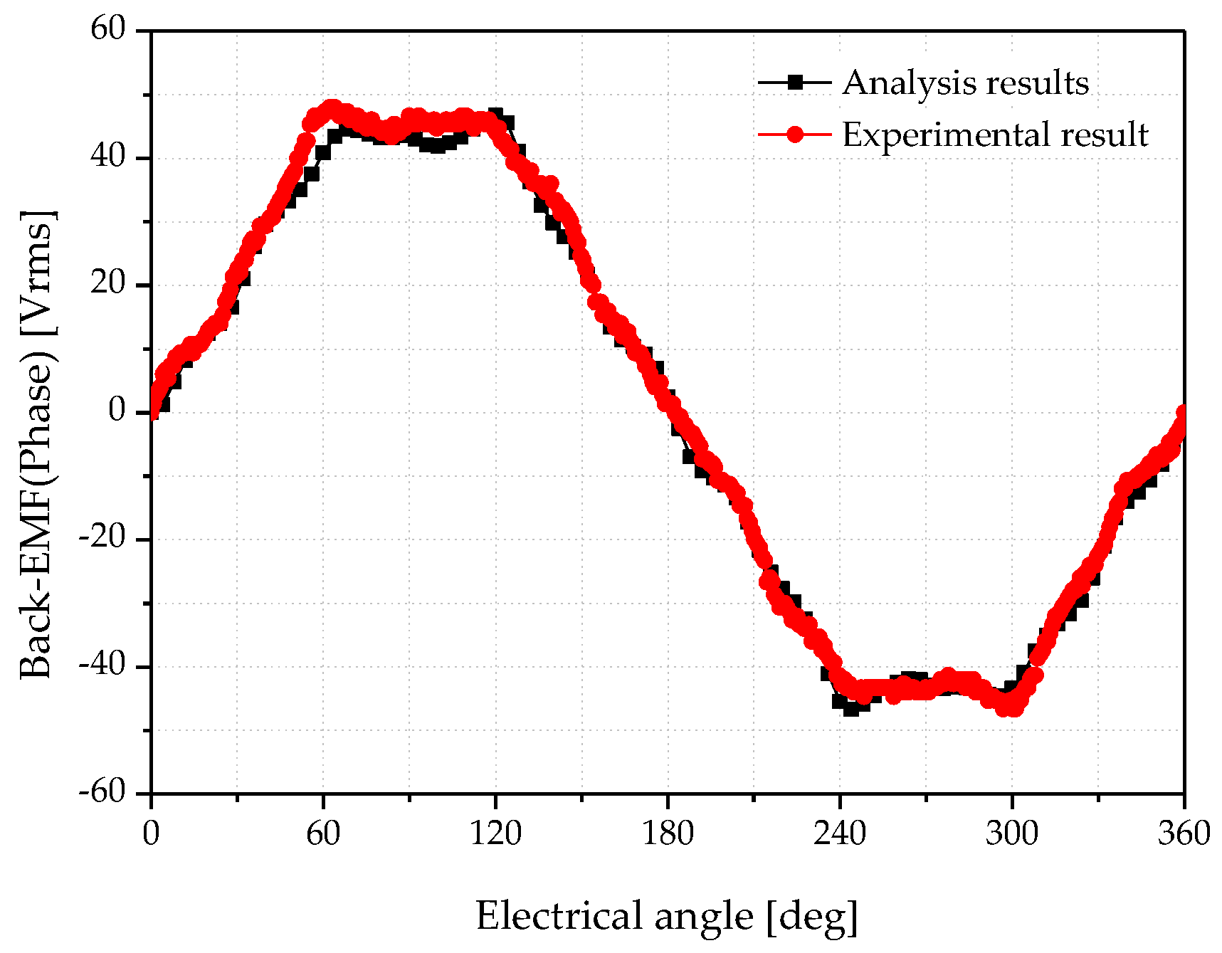
Figure 17.
Experimental results of the prototype at the rated load.
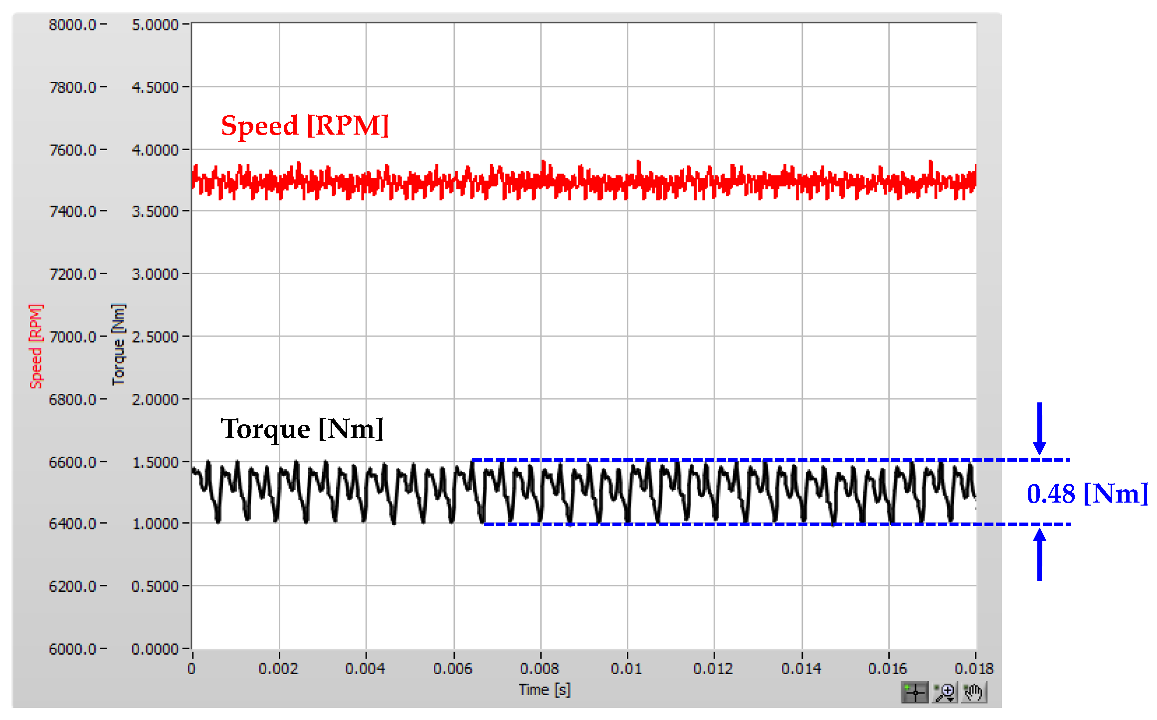

Table 1.
Specifications of the standard flared-shaped IPM model.
| Item | Unit | Value | - | |
|---|---|---|---|---|
| Number of poles / slots | - | 8 poles / 12 slots | - | |
| Stator | outer diameter | mm | Φ 95.0 | 35H270 |
| inner diameter | mm | Φ 53.5 | ||
| stack | mm | 27.5 | ||
| Rotor | outer diameter | mm | Φ 52.5 | 35H270 |
| inner diameter | mm | Φ 16.5 | ||
| stack | mm | 27.5 | ||
| Magnet | material | - | ferrite (9BE) | Br 0.42[T] |
| size | mm × deg. | 3.0 × 26.5 | (thickness × angle) | |
| Winding | material | - | copper | - |
| wire diameter × turns | - | Φ 1.0 × 30 turns | concentrated type | |
Table 2.
Analysis results at no-load.
| Item | Unit | Standard Flared IPM model |
Basic FCPM model |
Rate |
|---|---|---|---|---|
| Back-EMF (Phase) | Vrms | 45.46 | 28.32 | ▼37.7% |
| THD | % | 16.3 | 45.8 | ▲29.5% |
| Cogging torque | Nm | 0.210 | 0.134 | ▼36.2% |
Table 3.
Ranges of The design variables for LHS
| Design variable | Unit | Design limits | |
|---|---|---|---|
| Minimum | Maximum | ||
| x1 (magnet angle) | deg. | 55 | 95 |
| x2 (polar angle) | deg. | 25 | 45 |
Table 4.
Inner and outer radius for x1 setup
| Design variable | Unit | Design limits for x1 | |
|---|---|---|---|
| Minimum | Maximum | ||
| R1 (inner radius) | mm | 3.5 | 6.5 |
| R2 (outer radius) | mm | 6.5 | 9.5 |
Table 5.
Analysis results for DOE cases.
| Number of DOE |
x1 [deg.] |
x2 [deg.] |
Back-EMF [Vrms] |
THD [%] |
Cogging torque [Nm] |
|---|---|---|---|---|---|
| 1 | 61.5 | 38.4 | 28.77 | 43.6 | 0.134 |
| 2 | 78.4 | 37.5 | 31.46 | 9.1 | 0.101 |
| 3 | 82.7 | 40.2 | 31.20 | 9.8 | 0.086 |
| 4 | 64.1 | 33.1 | 32.63 | 25.0 | 0.107 |
| 5 | 58.3 | 40.9 | 32.54 | 11.6 | 0.097 |
| 6 | 75.8 | 36.9 | 31.61 | 11.6 | 0.107 |
| 7 | 91.0 | 38.7 | 30.68 | 8.3 | 0.092 |
| 8 | 75.8 | 40.0 | 31.60 | 9.1 | 0.089 |
| 9 | 65.9 | 41.8 | 32.24 | 14.7 | 0.098 |
| 10 | 59.9 | 28.9 | 33.25 | 38.9 | 0.085 |
| 11 | 65.9 | 41.7 | 32.24 | 14.2 | 0.097 |
| 12 | 81.3 | 44.0 | 31.58 | 22.9 | 0.076 |
| 13 | 58.3 | 27.2 | 32.32 | 43.4 | 0.151 |
| 14 | 72.2 | 39.0 | 31.77 | 7.7 | 0.096 |
| 15 | 89.2 | 27.8 | 24.45 | 42.3 | 0.074 |
| 16 | 81.3 | 43.6 | 31.57 | 21.2 | 0.083 |
| 17 | 74.6 | 39.2 | 31.64 | 7.8 | 0.094 |
| 18 | 75.8 | 42.2 | 31.78 | 16.1 | 0.094 |
| 19 | 62.3 | 26.6 | 30.52 | 45.1 | 0.150 |
| 20 | 65.0 | 37.0 | 32.19 | 11.0 | 0.110 |
| 21 | 75.8 | 38.8 | 31.54 | 7.9 | 0.096 |
| 22 | 59.9 | 41.2 | 32.51 | 12.7 | 0.098 |
| 23 | 65.0 | 38.6 | 32.14 | 7.7 | 0.100 |
| 24 | 92.3 | 29.0 | 29.32 | 22.8 | 0.127 |
| 25 | 77.1 | 40.4 | 31.42 | 10.1 | 0.087 |
| 26 | 68.9 | 29.0 | 31.89 | 38.5 | 0.073 |
| 27 | 64.1 | 41.6 | 32.37 | 13.7 | 0.097 |
| 28 | 89.2 | 33.2 | 30.95 | 24.7 | 0.104 |
| 29 | 84.3 | 44.6 | 31.35 | 24.7 | 0.065 |
| 30 | 62.3 | 40.7 | 32.34 | 11.0 | 0.094 |
Table 6.
Optimal points of the design variable.
| Item | x1 (Magnet angle) [deg.] |
x2 (Polar angle) [deg.] |
Magnet thickness [mm] |
|---|---|---|---|
| Basic model | 70.0 | 26.5 | 3.0 |
| Optimal model | 58.3 | 39.4 | 3.0 |
Table 7.
Analysis results at the no-load condition.
| Item | Unit | Basic FCPM model |
Optimal FCPM model |
Rate |
|---|---|---|---|---|
| Back-EMF (Phase) | Vrms | 28.32 | 32.43 | ▲14.5 % |
| THD | % | 45.8 | 7.5 | ▼38.3 % |
| Cogging torque | Nm | 0.134 | 0.100 | ▼25.4 % |
Table 8.
Analysis results at the rated load condition.
| Item | Unit | Basic FCPM model |
Optimal FCPM model |
Rate |
|---|---|---|---|---|
| Rated speed | rpm | 7,500 | 7,500 | - |
| Rated torque | Nm | 1.30 | 1.29 | - |
| Torque ripple (peak to peak) | Nm | 1.91 | 0.50 | ▼73.8 % |
| Rated current | Apeak | 15.3 | 12.8 | - |
| Copper loss | W | 93.8 | 65.6 | ▼30.1 % |
| Iron loss | W | 28.7 | 26.5 | ▼7.7 % |
| Hysteresis loss | W | 7.1 | 6.8 | ▼4.2 % |
| Output | W | 1,019.2 | 1,010.3 | - |
| Efficiency | % | 88.7 | 91.1 | ▲2.7 % |
Table 9.
Analysis results at the rated load condition.
| Item | Unit | Basic FCPM model | Optimal FCPM model | Rate | ||
| Analysis | Analysis | Experiment | ||||
| Back-EMF(Phase) | Vrms | 28.32 | 32.43 | 33.10 | ▲16.9% | |
| THD | 16.3 | 45.8 | 7.5 | ▼54.0% | ||
| Torque | average | Nm | 1.30 | 1.29 | 1.30 | - |
| ripple | Nm | 1.91 | 0.50 | 0.48 | ▼74.9% | |
| Copper loss | W | 93.8 | 65.6 | 64.8 | - | |
| Iron loss | W | 35.8 | 33.3 | 31.8 | - | |
| Output power | W | 1,019.2 | 1,010.3 | 1,010 | - | |
| Efficiency | % | 88.7 | 91.1 | 91.3 | ▲2.6% | |
Disclaimer/Publisher’s Note: The statements, opinions and data contained in all publications are solely those of the individual author(s) and contributor(s) and not of MDPI and/or the editor(s). MDPI and/or the editor(s) disclaim responsibility for any injury to people or property resulting from any ideas, methods, instructions or products referred to in the content. |
© 2024 by the authors. Licensee MDPI, Basel, Switzerland. This article is an open access article distributed under the terms and conditions of the Creative Commons Attribution (CC BY) license (http://creativecommons.org/licenses/by/4.0/).
Copyright: This open access article is published under a Creative Commons CC BY 4.0 license, which permit the free download, distribution, and reuse, provided that the author and preprint are cited in any reuse.