
Submitted:
29 December 2023
Posted:
04 January 2024
You are already at the latest version
Abstract
This study investigates the elastic buckling behaviour of skew Functionally Graded Material (FGM) thin plates featuring a circular opening. FGM materials, known for their unique property gradients, have gained prominence in structural engineering due to their mechanical performance and durability. Including a circular opening introduces a critical geometric consideration, influencing the structural stability and load-carrying capacity of FGM plates. The study examines the effects of the skew angle, plate’s aspect ratio, opening position, and size on the critical buckling load, normalized buckling load, and various buckling failure modes through computer modelling and finite element analysis. The results offer valuable insights into the interplay between material heterogeneity, geometric configuration, and structural stability. For instance, the critical buckling load increases by 29%, 82%, and 194% with the increment of skew angle from 0° to 30°, 45°, and 60°, respectively. Moreover, as the opening shifts from the plate’s edge closer to the center, the critical buckling load decreases by 26%. This research contributes to the advancement of understanding FGM thin plates’ behaviour under skew loading conditions, with implications for the design and optimization of innovative structures. The findings presented provide a foundation for further exploration of advanced composite materials and their applications in structural engineering.
Keywords:
Functionally Graded Material
; Elastic buckling
; Finite Element Analysis
; Skew Plates
; Thin Plates.
1. Introduction
Steel, ceramic, and composite thin plates are the basic components in most building structures, and their elastic behaviour has been heavily studied. Nevertheless, advancements in technology and manufacturing raise the need for a new set of materials with high tensile strength and lightweight. Functionally Graded Materials (FGM) are novel materials characterized by gradually varying properties with respect to their dimensions. Plates manufactured with FGM are microscopically heterogeneous and made from two isotropic materials: a metal and a ceramic. The utilization of FGM can be seen in several applications, such as construction, energy, and aerospace [1]. Elastic buckling indicates the sudden deformation of structures; hence, investigating buckling performance is of much interest in structural engineering [2]. Numerous research has been conducted on optimizing and enhancing the buckling behaviour of various structures [3,4,5,6]. The utilization of FGMs yields an increase in the modules of elasticity of the pristine material and an improvement in the thermal and mechanical properties [7], [8]. Hence, employing FGMs is one method to improve the buckling strength of structures under compression [9]. Kumar et al. [10] explored the behaviour of a porous tapered FGM plate subjected to both uniaxial and biaxial buckling loads. The simulation results showed that the buckling loads of the FGM plates can be efficiently and simply calculated through simple power and sigmoidal gradation laws. Moreover, the buckling load increases with the increase of the boundary constrains and the taper ratio. Recent research initiatives have increasingly utilized finite element analysis software as a strategic tool to mitigate experimental challenges, reduce time, and lower costs [11,12,13]. Sitli et al. [14] proposed a finite element model to investigate the buckling and post-buckling analysis of a FGM plate. The method showed good accuracy when validated with model from ABAQUS software. Dhuria et al. [15] studied the impact of porosity on the static buckling response of a functionally graded plate. The results show that the buckling loads of plates subjected to uniaxial buckling loading is higher compared to biaxial loading. Moreover, the buckling loads increase with the increase of the span-thickness ratio.
The geometry of thin plates plays a vital role in their buckling behaviour, where the presence of a cutout and its position might adversely affect the buckling load. Moreover, the variation of the aspect ratio and skew angle of skewed plates significantly alters the elastic buckling behaviour. The presence of cutouts is essential as numerous applications require their presence. Van et al. [16] investigated the static bending and buckling characteristics of bi-directional functionally graded plates incorporating cutouts. The computational findings indicated that augmenting the plate thickness leads to a reduction in the buckling capacity. Additionally, the deflection of the plates rises in tandem with an increase in thickness. Jamali et al. [17] studied the post-buckling analysis of functionally graded carbon nanotube plates with square cutouts. The results reported that post-buckling load decreases with the increase in the plate’s dimensions. Furthermore, increasing the cutout length reduces the stiffness and, in turn, the buckling load. Thanh et al. [18] examined the static bending behaviour of micro-plates made of porous FGM employing geometrically nonlinear analysis. The findings indicate that including porosity leads to a reduction in the elasticity modulus. Consequently, FGM plates with greater porosity exhibit increased deflection. Prabowo et al. [19] investigated the effect of the plate’s thickness on the buckling of the plate. It was reported that the buckling load and the plate’s thickness are directly proportional, where an increase in the thickness reflects an increase in the buckling load. Alashkar et al. [20] investigated the effect of the arrangement of several openings on the buckling load of an FGM plate. The results showed that vertically arranged openings exhibited the lowest buckling load, while horizontally arranged ones showed the highest. Furthermore, the effect of the plate’s dimension on the buckling load was studied. The buckling load increased with the increase in the thickness of the plate and decreased with the increase of the plate’s opening. Elkafrawy et al. [21] studied the effect of the opening shape on the buckling load of FGM thin plates. The results showed that opening with a diamond shape exhibited the best buckling performance compared to circular and square-shaped openings, respectively.
Skew thin plates are interesting since they are heavily employed in skewed bridges and airplane fuselage panels. For instance, Civalek and Jalaei et al. [22] applied a discrete singular convolution method to study the buckling behaviour of FGM skew plates. The numerical results reported that the buckling load decreases with the plate’s skew angle and aspect ratio increase. Moreover, increasing the thickness of the plate adversely affected the buckling load. Duan et al. [23] investigated the elastic buckling of skew thick microplates subjected to compressive loading and in-plane shear. The study concluded that the critical buckling load increases monotonically with the increase in skew angle for both uniaxial and biaxial loadings. Singh and Prasad et al. [24] studied the buckling response of skew sandwich plates. The simulation results concluded that increasing the skew angle improved the buckling performance. Although extensive research has been conducted on buckling structures with openings, only a few considered skew plates with openings. Nejad et al. [25] examined the carried buckling performance of skew thin plates with cutouts. The numerical results demonstrated that increasing the opening size negatively affects the plate’s buckling load. Yuan et al. [26] investigated the shear buckling behaviour of FGM skew nanoplates. The numerical results displayed that an increase in the skew angle increases the shear buckling of the plates. Shahrestani et al. [27] evaluated the buckling behaviour of skew FGM plates with circular openings. The numerical results illustrated a directly proportional relationship between the plate’s thickness and the elastic and inelastic buckling loads. The same relation was presented between the skew angle and the buckling loads.
The preceding literature highlights the significance of examining the performance of skew thin plates under different buckling conditions, particularly concerning their dependence on geometrical parameters. However, a limited number of studies address the buckling behaviour of FGM skew thin plates containing openings. Consequently, this study delves into the elastic buckling performance of FGM skew plates featuring a circular cutout. Variations in the skew angle are explored to elucidate the effect of skew plates. Additionally, altering both the size and position of the circular cutout relative to the plate’s edge, as well as the aspect ratio of the plate, is carried out herein to assess their influence on the plate’s buckling characteristics. This research comprehensively evaluates the buckling behaviour exhibited by thin skew FGM plates with a circular cutout. FGM materials are of paramount importance for investigation, as they demonstrate significant potential as composite materials, combining the exceptional properties of ceramics and metals. The ceramic component notably enhances resistance to thermal and corrosive factors, while the metal component bolsters mechanical features like fracture toughness, load-bearing capacity, and elasticity modulus.
2. Materials and Methods
The computational Finite Element Analysis (FEA) of the skew FGM thin plate is carried through the ABAQUS software package [28]. The proposed model is verified through a comparison with the buckling loads reported by Ali et al. [29]. A simply supported FGM plate with a thickness of 4 inches is utilized for verification. Figure 1 shows the schematic diagram of the studied skew FGM thin plate with the applied loads and boundary conditions. For the FEA, the ABAQUS selected element type, 3D S4R, is well-suited for addressing such geometries. S4R is characterized by four sides and doubly curved 3D shell properties with reduced integration. This reduction aids in achieving a solution without encountering convergence challenges, as it employs the minimal set of Gaussian coordinates for integration. Moreover, the mesh size is restricted to 10 10 mm2, with each node freely moving in six degrees of freedom, encompassing translations and rotations along the x, y, and z axes.
Figure 2 illustrates the procedural flow of the conducted analysis, encompassing parametric investigations. Following model verification, explorations into key aspects such as skew angle, aspect ratio, and cutout position are pursued to inspect the thin plate’s critical buckling load and buckling characteristics. In the initial investigation, the skew angle is adjusted within a range of 0°, 30°, 45°, and 60° while maintaining constant values for the plate’s thickness, width, height, and opening diameter. In the subsequent investigation, the plate's aspect ratio (a/b) is modified to assess its influence on the critical and normalized buckling loads. The aspect ratio is shifted from 1 (representing a square plate) to 2, 3, and 4, with the plate’s thickness, height, and skew angle remaining unchanged throughout this study. In the third investigation, the positioning of the opening relative to the plate’s edge is altered based on the x/a ratio, aiming to discern its impact on the plate’s critical buckling load. The x/a ratio varies from 0 to 0.125, 0.25, 0.375, and 0.5. The plate’s dimensions and skew angle are held constant throughout these analyses. Examining the relationship between the cutout size and buckling behaviour is also undertaken. This involves modifying the diameter-to-plate-height ratio (d/b) from 0 to 0.2, 0.4, and 0.6, respectively.
Functionally Graded Materials have a gradient in composition, structure, and properties within a single material. This means the material’s properties vary smoothly from one end to the other, allowing it to possess tailored characteristics for specific applications. For example, the ceramic end might have high hardness and wear resistance in a ceramic-metal FGM, while the metal end could have high toughness and ductility. This gradient in properties can be finely controlled. The modulus of elasticity of the FGM material can be calculated from the following equation:
where , , and are the moduli of elasticity of the FGM, ceramic, and metal, respectively. The modulus of elasticity of the ceramic and metal are 380 GPa and 208 GPa, respectively. The volume fraction () is calculated from the following equation:
where is the plate’s thickness, z is the position of the material with respect to the thickness of the plate, and p is the power index, which is set at 1. The volume fraction is also set to 0.5 in this study.
The critical buckling load of the skew FGM thin plates under uniaxial loading can be calculated through the Galerkin equation as follows [30]:
where and are the number of half waves in the x and y directions, respectively, while a and b are the plate’s length and width, respectively.
The position vector of any random point is obtained under the assumption that the transverse strains are negligible. The position vector is as follows:
The strain is obtained as follows:
where and are
The stress for the FGM plate can be calculated from the following relations:
where is the Poisson’s ratio assumed to be 0.3.
The stress components per unit length at the midpoint of the surface are determined through the integration of stresses across the thickness of the plate. By incorporating the stress-strain relationship into these stress components, the axial and bending moments can be represented in matrix form as outlined below:
The flexural rigidity of the FGM plate, which represents the resistance of the plate while undergoing bending, with a constant Poisson's ratio and a varying modulus of elasticity, can be calculated through the following equation [31]:
Given the structure, FGM material applied loads, and boundary conditions investigated in this study, the coefficients , , and are obtained as shown below:
The flexural rigidity of FGM plates with a metal/ceramic material is evaluated through the following equation:
Where
Nevertheless, the term for a uniformly graded isotropic and homogenous plate, thus Eq. (13) is reduced to the well-known formula for the flexural rigidity of a plate:
3. Results and Discussion
3.1. Model Verification
Figure 3 compares the buckling load between the proposed model and the data obtained from [29]. It is seen that the model accurately describes the relationship between the aspect ratio and the buckling load. Moreover, the accuracy of the model increases as the aspect ratio increases. For instance, the percentage error decreases from 9.6% for an aspect ratio of 10 to a percentage error of 0.5% for an aspect ratio of 80. Thus, the proposed model displays close proximity to the published results.
3.2. Parametric Investigation
A parametric investigation is carried out to study the effect of varying skew angle, cutout size and position, and aspect ratio of the plate on the buckling performance. Figure 4 shows an example of the mesh detail for the skew FGM thin plate. The finely tuned mesh allows for precise geometry representation, ensuring that localized phenomena, such as stress concentrations and deformation patterns, are accurately captured. Moreover, it strikes a crucial balance between computational resources and accuracy, optimizing the trade-off between refinement and simulation speed.
Figure 5 shows the variation of the skew angle, the plate’s aspect ratio, and the cutout size and position on the critical buckling load of the FGM thin plate. A quick inspection of Figure 5 (a) reveals that the skew angle and critical buckling load are directly proportional. For instance, varying the skew angle from 0° to 30°, 45°, and 60° increases the critical buckling load from 1,552 kN to 2,308 kN, 4,021 kN, and 8,450 kN, respectively. Table 1 shows the critical buckling load values for various skew angles and opening sizes. The enhancement of the buckling load with the skew angle can be attributed to the improved and more efficient distribution of the applied load. Moreover, the presence of the cutout and its interaction with the skew angle may result in stabilizing the plate and increasing the critical buckling load.
Figure (b) demonstrates that the critical buckling load decreases as the aspect ratio increases. This change is evident as the plate transitions from square (a/b = 1) to rectangular geometry (a/b = 2). For instance, the critical buckling load decreases from 9,922 kN to 2,469 kN, 1,128 kN, and 657 kN as the aspect ratio increases from 1 to 4, respectively.
Table 2 compares the critical buckling loads for varying opening sizes and aspect ratios. As the aspect ratio increases, the plate becomes relatively slimmer making it more prone to buckling because it is less capable of resisting lateral deflection under an axial load. Moreover, higher aspect ratios typically result in greater flexibility in the direction perpendicular to the longer dimension. This increased flexibility makes the plate more susceptible to buckling. A higher aspect ratio introduces significant bending effects in addition to the axial load. This means the plate experiences axial compression and bending moments, which can lead to buckling at a lower overall load. The increased length of the plate compared to its width can result in a reduction in effective stiffness, making it easier for the plate to deflect laterally under load, thus increasing its susceptibility to buckling.
Figure 5 (c) shows that the position of the cutout relative to the plate edge plays a vital role in the buckling performance of the plate. The critical buckling load decreases as the cutout moves away from the edge and closer to the center. For example, the critical buckling load of the plate decreased from 915 kN to 913 kN, 905 kN, 892 kN, and 885 kN as opening position ratio increased from 0 to 0.125, 0.25, 0.375, and 0.5, respectively. Table 3 displays the values of the critical buckling load as the opening position and size varied.
As can be noticed from all the parametric investigations, the critical buckling load decreases with the presence of a cutout and the increase in size. This relation is demonstrated in Figure 5. The presence of an opening reduces the effective cross-sectional area of the plate. With less available material to resist the compressive load, the plate cannot support high loads before buckling occurs. Moreover, openings create stress concentrations around their edges. This localized increase in stress makes the area surrounding the opening more susceptible to failure, which can lead to an earlier onset of buckling. An opening can alter the load path within the plate, weaken specific sections, and reduce the stiffness of the plate. These changes in load distribution can lead to a more complex stress state, potentially resulting in a lower critical buckling load and making the plate more susceptible to buckling.
The normalized buckling load is crucial to investigate for its role in facilitating meaningful comparisons between different structural elements or configurations. In this case, the normalized load is obtained by expressing the critical buckling load relative to a control or reference value, a plate with no opening. It is utilized to assess the relative stability and performance of various cases, irrespective of their specific dimensions or units of measurement. This comparative analysis is instrumental in optimizing material usage and minimizing costs, especially when selecting the most efficient designs or materials. Normalized values also contribute to developing standardized design guidelines, simplifying the engineering process, and ensuring consistent practices. Furthermore, it aids in accurately predicting the behaviour of full-scale structures based on scaled-down model testing, a vital consideration in experimental studies.
Figure 6 shows the effect of varying the opening size on the normalized buckling load of the plate for various skew angles, aspect ratio, and opening position. Inspection of Figure 6 (a) shows an inverse relation between the opening aspect ratio and the normalized buckling load. For example, the normalized critical buckling load reduced from 1 to 0.93 to 0.78 to 0.58 when the aspect ratio varied from 0 to 0.2 to 0.4 and 0.6, respectively, for a 30 skew angle. On the other hand, the relation concerning the variation of the skew angle and normalized critical buckling load is not as monotonic. The introduction of a skew angle reduces the critical buckling load, and that reduction grows until a skew angle of 60, where a rise in the normalized buckling load is reported. For instance, for a plate with an opening aspect ratio of 0.2, the normalized buckling load decreases from 0.937 to 0.932 as the skew angle increases from 30 to 45. However, as the skew angle increased to 60, the normalized buckling load increased to 0.973. This relation was reported for all opening sizes and aspect ratios.
Figure 6 (b) displays the variation of the normalized critical buckling with the aspect ratios of the FGM skew thin plates. Inspection of the graph shows that the normalized critical buckling load is inversely proportional to the opening aspect ratio of the FGM thin plate. For instance, the normalized critical buckling load reduced from 1 to 0.90, 0.71, and 0.51 when the opening aspect ratio increased from 0 to 0.2 to 0.4 to 0.6, respectively. On the other hand, the thin plates' normalized critical buckling load increases with the aspect ratio increase. For example, for a thin plate with ratio of 0.2, the normalized buckling load increased from 0.90 to 0.93 to 0.95 to 0.96 as the aspect ratio increased from 1 to 4, respectively. Figure 6 (c) represents the effect of the opening size and position on the normalized critical buckling of the FGM skew thin plates. The graph shows that the normalized critical buckling load is inversely proportional to the opening size. For instance, for an ratio of 0.5, the normalized critical buckling decreased from 0.96 to 0.72 as the opening ratio increased from 0.2 to 0.6. Moreover, the position of the opening influences the critical buckling load. This effect can be seen clearly for openings near the plate's center, as the critical buckling load decreases as the opening shifts from the plate’s edge to the center. For example, for a position ratio = 0.5, the increase of the ratio from 0.2 to 0.6 decreased the normalized critical buckling load by 0.25. On the other hand, for = 0.125, the same increase in the opening size only resulted in a decrease of 0.02 in the normalized critical buckling load.
The ABAQUS software package lists mode shapes and their corresponding eigenvalues in a typical buckling analysis. Each mode shape corresponds to a specific deformation pattern or mode the structure can undergo during buckling. For instance, the first buckling mode represents the most critical deformation pattern associated with the lowest eigenvalue. This mode typically involves the primary or global deformation of the structure. The second buckling mode represents the next most critical deformation pattern. It is orthogonal to the first mode, i.e., independent of and distinct from the first mode. The third buckling mode represents the third most critical deformation pattern, orthogonal to all other modes. Similar to modes 1 through 3, this fourth buckling mode represents another distinct deformation pattern. The number indicates its rank in terms of criticality. Figure 7 shows the first four buckling modes of FGM thin plates with various skew angles and opening aspect ratios. The figure shows a snippet of various opening aspect ratios and skew angles; nevertheless, the distribution of the buckling stress is the same across different skew angles with a specific opening aspect ratio and vice versa. In the first buckling mode, it is seen that the maximum buckling stress is situated in the middle of the FGM plate. However, as the opening diameter and skew angle increase, the maximum stress shifts to the sides of the FGM plate. The second buckling mode displays two patches of maximum stress at the plate’s sides. The third buckling mode shows that the maximum stress is limited to the top and bottom regions of the plate. As the opening size increases, a maximum stress region is developed around the opening. For the fourth buckling mode, three regions of maximum stress are present.
Figure 8 portrays FGM skew thin plates’ first four buckling modes with various aspect ratios. The figure only reveals a fragment of various openings and plate aspect ratios; nonetheless, the buckling stress is distributed in the same manner across various aspect ratios for the same opening aspect ratio. Examination of the figure reveals that the maximum stress is concentrated in the middle of the FGM thin plate for the first buckling mode. As the opening size increases, the maximum stress shifts to the boundary of the plate. In the second buckling mode, the maximum stress shifts to a limited region at the top and bottom of the plate. The same distribution is noticed for the third buckling mode as well. The fourth buckling mode shows two regions of maximum stress located at the sides of the plate. As the opening size increases, maximum stress patches develop at the region surrounding the opening.
Figure 9 shows the variation of size and position of the circular opening on the first four buckling modes of the FGM skew thin plates. Inspecting the figure reveals that the presence of an opening and varying its size and position does not affect the buckling stress arrangement in the thin plates. Moreover, the stress distribution remains constant regardless of the opening’s position and size. In the first buckling mode, the maximum stress is seen in the mid-region of the plate, with the stress decreasing closer to the edges. As for the later buckling modes, it is shown that the maximum stress region decreases in size and shifts to the top and bottom edges of the plate. For the second and third modes, one region of maximum stress is displayed at the top left of the plate, while another can be seen on the opposite side (bottom right). Nevertheless, two regions of maximum stress can be seen at the top and bottom of the FGM thin plates for the fourth buckling mode.
4. Conclusions
This paper computationally modelled the buckling performance of skew thin FGM plates with a cutout using the ABAQUS finite element analysis software. Subsequent to the model verification, parametric studies were carried out to investigate the effect of the skew angle, aspect ratio, and cutout size and position on the critical buckling load of the plate. The normalized buckling load was also calculated and compared as it provides a standardized framework for comparative analysis, allowing for the focus on fundamental structural behaviour without constraints of specific dimensional considerations. To better understand the structural buckling behaviour of the skew FGM thin plate, the buckling modes are investigated as they identify the critical failure mechanisms and design structures to withstand potential buckling. The results can be summarized as follows:
- The presence of a cutout and the increase in its size decreases the critical buckling load of the plate.
- Thin plates with skew angle of 60° obtained higher critical buckling loads by 206%, 134%, and 65%, compared to plates with skew angles of 0°, 30°, and 45°, respectively.
- An inversely proportional relationship between the critical buckling load and the aspect ratios of the plate is present.
- The position of the opening also affects the buckling load, as an opening closer to the plate’s edge showed a higher buckling load than that close to the center of the plate.
Author Contributions
Conceptualization, A.A. and M.E; methodology, A.A and M.E.; software, M.E. and A.A.; validation, A.A and M.E. ; formal analysis, A.A and M.E. ; investigation, A.A and M.E.; resources, A.A., M.E and R.H.; data curation, M.E. and A.A.; writing—original draft preparation, A.A and M.E.; writing—review and editing, A.A, M.E., R.H. and M.A.; visualization, A.A and M.E. ; supervision, R.H. and M.A.; project administration, R.H. and M.A.; funding acquisition, R.H. All authors have read and agreed to the published version of the manuscript.
Funding
This research was financially supported by the American University of Sharjah (AUS) through the Faculty Research Grant program (FRG20-M-E152), and the Open Access Program (OAP).
Acknowledgments
This research was financially supported by the American University of Sharjah (AUS) through the Open Access Program (OAP). The authors greatly appreciate the financial support. This paper represents the opinions of the authors and does not mean to represent the position or opinions of AUS.
Conflicts of Interest
The authors declare no conflict of interest.
References
- Saleh, B.; Jiang, J.; Fathi, R.; Al-Hababi, T.; Xu, Q.; Wang, L.; Song, D.; Ma, A. 30 Years of functionally graded materials: An overview of manufacturing methods, Applications and Future Challenges. Compos. Part B: Eng. 2020, 201, 108376. [Google Scholar] [CrossRef]
- Elishakoff, I.; Eisenberger, M.; Delmas, A. Buckling and Vibration of Functionally Graded Material Columns Sharing Duncan's Mode Shape, and New Cases. Structures 2016, 5, 170–174. [Google Scholar] [CrossRef]
- Zhang, X.; Wang, Y.; Foster, A.; Su, M. Elastic local buckling behaviour of beetle elytron plate. Thin-Walled Struct. 2021, 165, 107922. [Google Scholar] [CrossRef]
- Fieber, A.; Gardner, L.; Macorini, L. Formulae for determining elastic local buckling half-wavelengths of structural steel cross-sections. J. Constr. Steel Res. 2019, 159, 493–506. [Google Scholar] [CrossRef]
- Peng, C.; Tran, P.; Mouritz, A.P. Compression and buckling analysis of 3D printed carbon fibre-reinforced polymer cellular composite structures. Compos. Struct. 2022, 300. [Google Scholar] [CrossRef]
- Khoram-Nejad, E.S.; Moradi, S.; Shishehsaz, M. Effect of crack characteristics on the vibration behavior of post-buckled functionally graded plates. Structures 2023, 50, 181–199. [Google Scholar] [CrossRef]
- Moita, J.S.; Araújo, A.L.; Correia, V.F.; Soares, C.M.M. Mechanical and thermal buckling of functionally graded axisymmetric shells. Compos. Struct. 2020, 261, 113318. [Google Scholar] [CrossRef]
- Hosseini, S.M.H.; Arvin, H. Thermo-rotational buckling and post-buckling analyses of rotating functionally graded microbeams. Int. J. Mech. Mater. Des. 2021, 17, 55–72. [Google Scholar] [CrossRef]
- Zenkour, A.M.; Aljadani, M.H. Buckling analysis of actuated functionally graded piezoelectric plates via a quasi-3D refined theory. Mech. Mater. 2020, 151, 103632. [Google Scholar] [CrossRef]
- Kumar, V.; Singh, S.; Saran, V.; Harsha, S. Effect of elastic foundation and porosity on buckling response of linearly varying functionally graded material plate. Structures 2023, 55, 1186–1203. [Google Scholar] [CrossRef]
- Khalil, A.E.-H.; Etman, E.; Atta, A.; Essam, M. Nonlinear behavior of RC beams strengthened with strain hardening cementitious composites subjected to monotonic and cyclic loads. Alex. Eng. J. 2016, 55, 1483–1496. [Google Scholar] [CrossRef]
- AlHamaydeh, M.; Elkafrawy, M.; Banu, S. Seismic Performance and Cost Analysis of UHPC Tall Buildings in UAE with Ductile Coupled Shear Walls. Materials 2022, 15, 2888. [Google Scholar] [CrossRef] [PubMed]
- Khalil, A.; Elkafrawy, M.; Abuzaid, W.; Hawileh, R.; AlHamaydeh, M. Flexural Performance of RC Beams Strengthened with Pre-Stressed Iron-Based Shape Memory Alloy (Fe-SMA) Bars: Numerical Study. Buildings 2022, 12, 2228. [Google Scholar] [CrossRef]
- Sitli, Y.; Mhada, K.; Bourihane, O.; Rhanim, H. Buckling and post-buckling analysis of a functionally graded material (FGM) plate by the Asymptotic Numerical Method. Structures 2021, 31, 1031–1040. [Google Scholar] [CrossRef]
- Dhuria, M.; Grover, N.; Goyal, K. Influence of porosity distribution on static and buckling responses of porous functionally graded plates. Structures 2021, 34, 1458–1474. [Google Scholar] [CrossRef]
- Van Vinh, P.; Van Chinh, N.; Tounsi, A. Static bending and buckling analysis of bi-directional functionally graded porous plates using an improved first-order shear deformation theory and FEM. Eur. J. Mech. - A/Solids 2022, 96. [Google Scholar] [CrossRef]
- MJamali; Shojaee, T. ; Mohammadi, B.; Kolahchi, R. Cut out effect on nonlinear post-buckling behavior of FG-CNTRC micro plate subjected to magnetic field via FSDT. Adv. Nano Res. 2019, 7, 405–417. [Google Scholar] [CrossRef]
- Le Thanh, C.C.; Nguyen, T.N.T.N.; Vu, T.H.T.H.; Khatir, S.; Wahab, M.A. A geometrically nonlinear size-dependent hypothesis for porous functionally graded micro-plate. Eng. Comput. 2022, 38, 449–460. [Google Scholar] [CrossRef]
- Prabowo, A.R.; Ridwan, R.; Muttaqie, T. On the Resistance to Buckling Loads of Idealized Hull Structures: FE Analysis on Designed-Stiffened Plates. Designs 2022, 6, 46. [Google Scholar] [CrossRef]
- Alashkar, A.; Elkafrawy, M.; Hawileh, R.; AlHamaydeh, M. Buckling Analysis of Functionally Graded Materials (FGM) Thin Plates with Various Circular Cutout Arrangements. J. Compos. Sci. 2022, 6, 277. [Google Scholar] [CrossRef]
- Elkafrawy, M.; Alashkar, A.; Hawileh, R.; AlHamaydeh, M. FEA Investigation of Elastic Buckling for Functionally Graded Material (FGM) Thin Plates with Different Hole Shapes under Uniaxial Loading. Buildings 2022, 12, 802. [Google Scholar] [CrossRef]
- Civalek, O.; Jalaei, M.H. Buckling of carbon nanotube (CNT)-reinforced composite skew plates by the discrete singular convolution method. Acta Mech. 2020, 231, 2565–2587. [Google Scholar] [CrossRef]
- Duan, Y.; Zhang, B.; Zhang, X.; Zhang, L.; Shen, H. Accurate mechanical buckling analysis of couple stress-based skew thick microplates. Aerosp. Sci. Technol. 2023, 132. [Google Scholar] [CrossRef]
- Singh, J.; Prasad, R.B. Vibration and Buckling Analysis of Skew Sandwich Plate using Radial Basis Collocation Method. Mech. Adv. Compos. Struct. 2017, 10, 383–392. [Google Scholar] [CrossRef]
- Nejad, A.T.; Shanmugam, N. Elastic buckling of uniaxially loaded skew plates containing openings. Thin-Walled Struct. 2011, 49, 1208–1216. [Google Scholar] [CrossRef]
- Yuan, Y.; Zhao, K.; Sahmani, S.; Safaei, B. Size-dependent shear buckling response of FGM skew nanoplates modeled via different homogenization schemes. Appl. Math. Mech. 2020, 41, 587–604. [Google Scholar] [CrossRef]
- Shahrestani, M.G.; Azhari, M.; Foroughi, H. Elastic and inelastic buckling of square and skew FGM plates with cutout resting on elastic foundation using isoparametric spline finite strip method. Acta Mech. 2018, 229, 2079–2096. [Google Scholar] [CrossRef]
- Systems, D. Abaqus: Finite Element Analysis for Mechanical Engineering And Civil Engineering. Available online: https://www.3ds.com/products-services/simulia/products/abaqus/ (accessed on 17 May 2023).
- Ali, E.Y.; Bayleyegn, Y.S. Analytical and numerical buckling analysis of rectangular functionally-graded plates under uniaxial compression. Struct. Stab. Res. Counc. Annu. Stab. Conf. 2019, 2, 534–547. [Google Scholar]
- Shariat, B.S.; Javaheri, R.; Eslami, M. Buckling of imperfect functionally graded plates under in-plane compressive loading. Thin-Walled Struct. 2005, 43, 1020–1036. [Google Scholar] [CrossRef]
- Chi, S.-H.; Chung, Y.-L. Mechanical behavior of functionally graded material plates under transverse load—Part I: Analysis. Int. J. Solids Struct. 2006, 43, 3657–3674. [Google Scholar] [CrossRef]
Figure 1.
Schematic of the skew FGM thin plate with applied loads and boundary conditions.
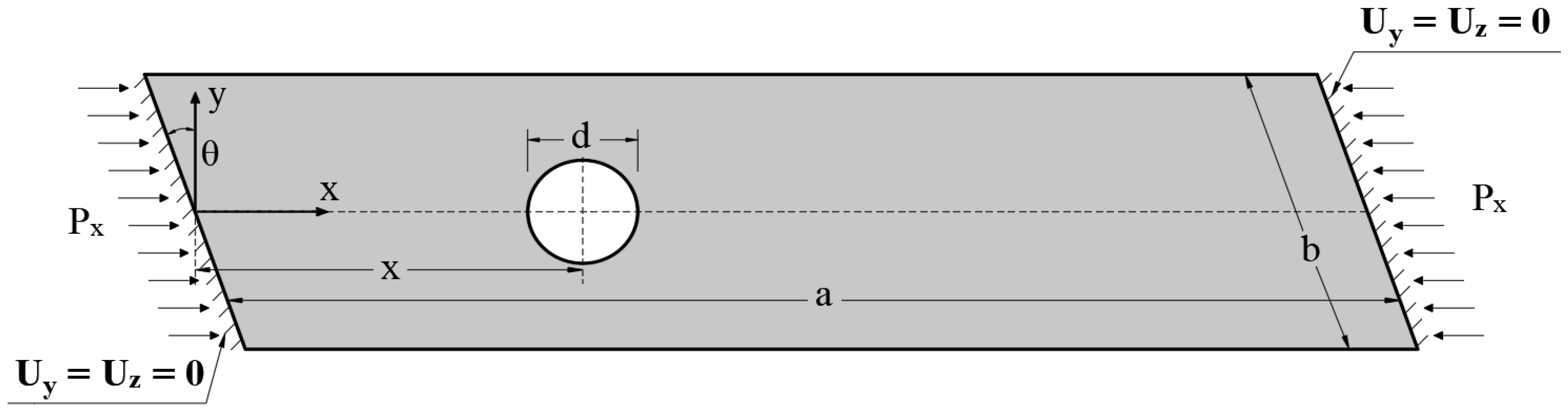
Figure 2.
Flowchart of the methodology.
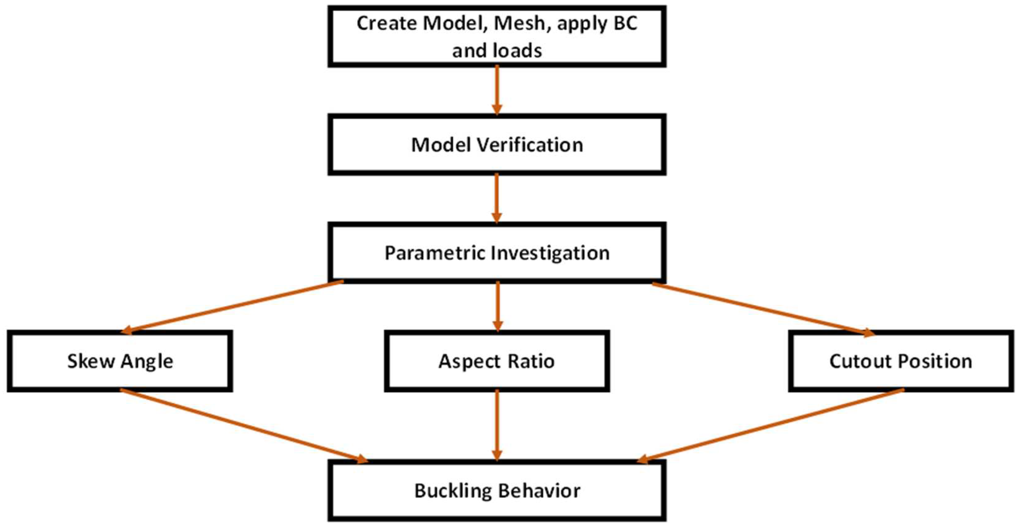
Figure 3.
Comparison between the buckling load of the proposed model and data published in [29].
Figure 3.
Comparison between the buckling load of the proposed model and data published in [29].
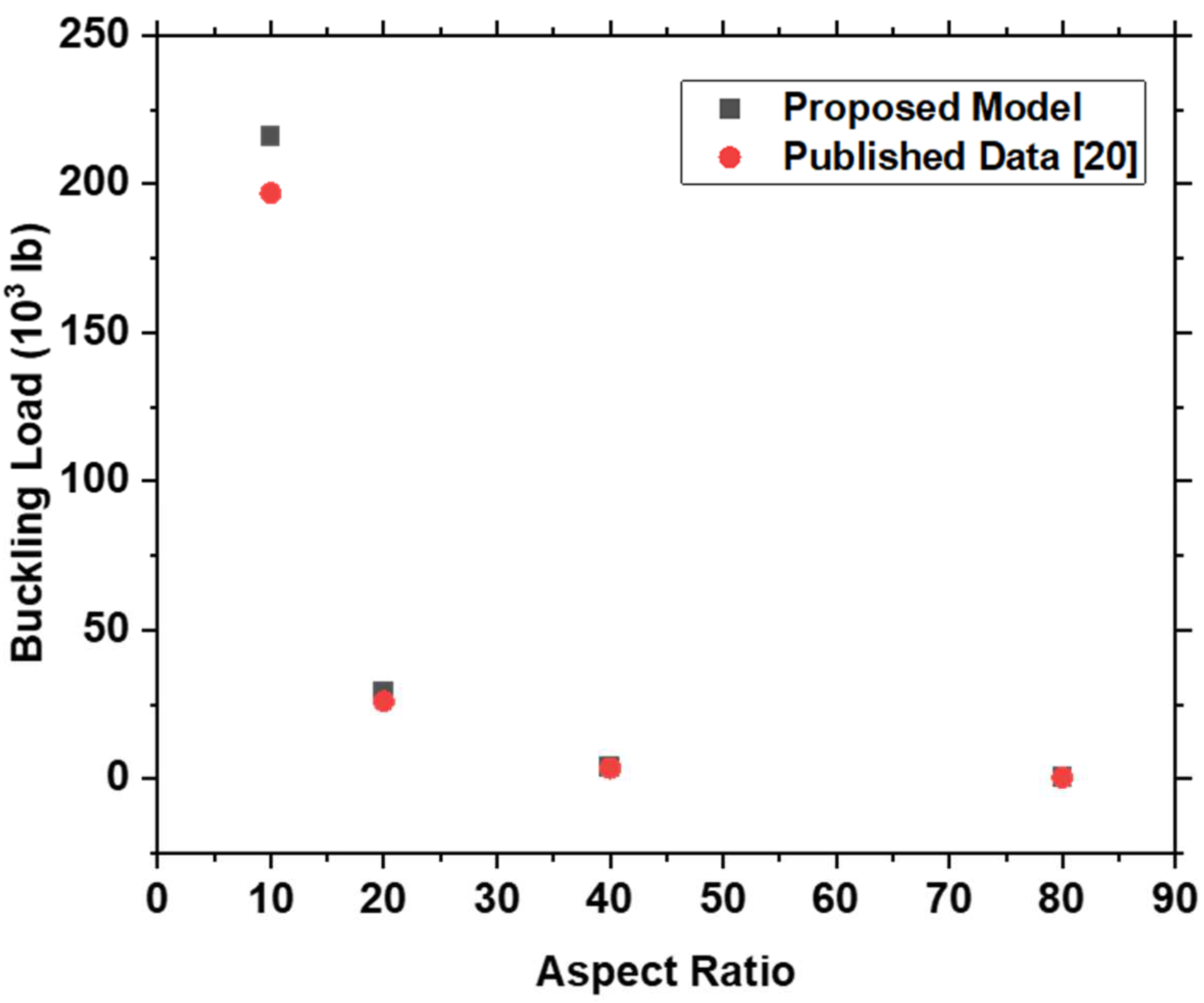
Figure 4.
Mesh details for skew FGM thin plates with cutout.
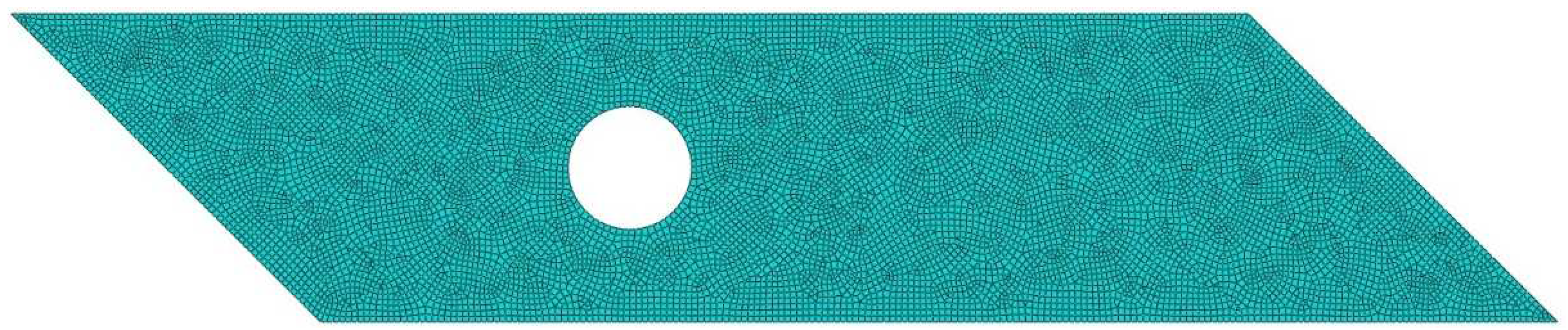
Figure 5.
The variation of the critical buckling load with (a) skew angle, (b) aspect ratio, and (c) cutout position.
Figure 5.
The variation of the critical buckling load with (a) skew angle, (b) aspect ratio, and (c) cutout position.
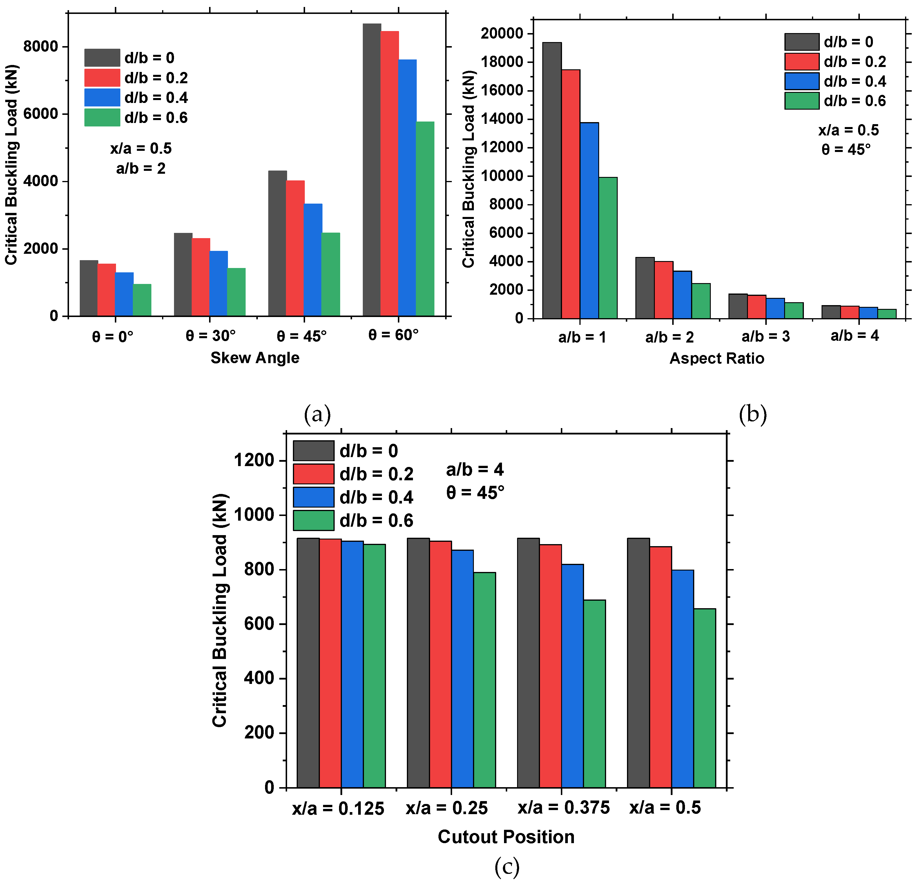
Figure 6.
The variation of the normalized critical buckling load with the cutout aspect ratio and (a) skew angle, (b) plate’s aspect ratio, and (c) cutout position.
Figure 6.
The variation of the normalized critical buckling load with the cutout aspect ratio and (a) skew angle, (b) plate’s aspect ratio, and (c) cutout position.
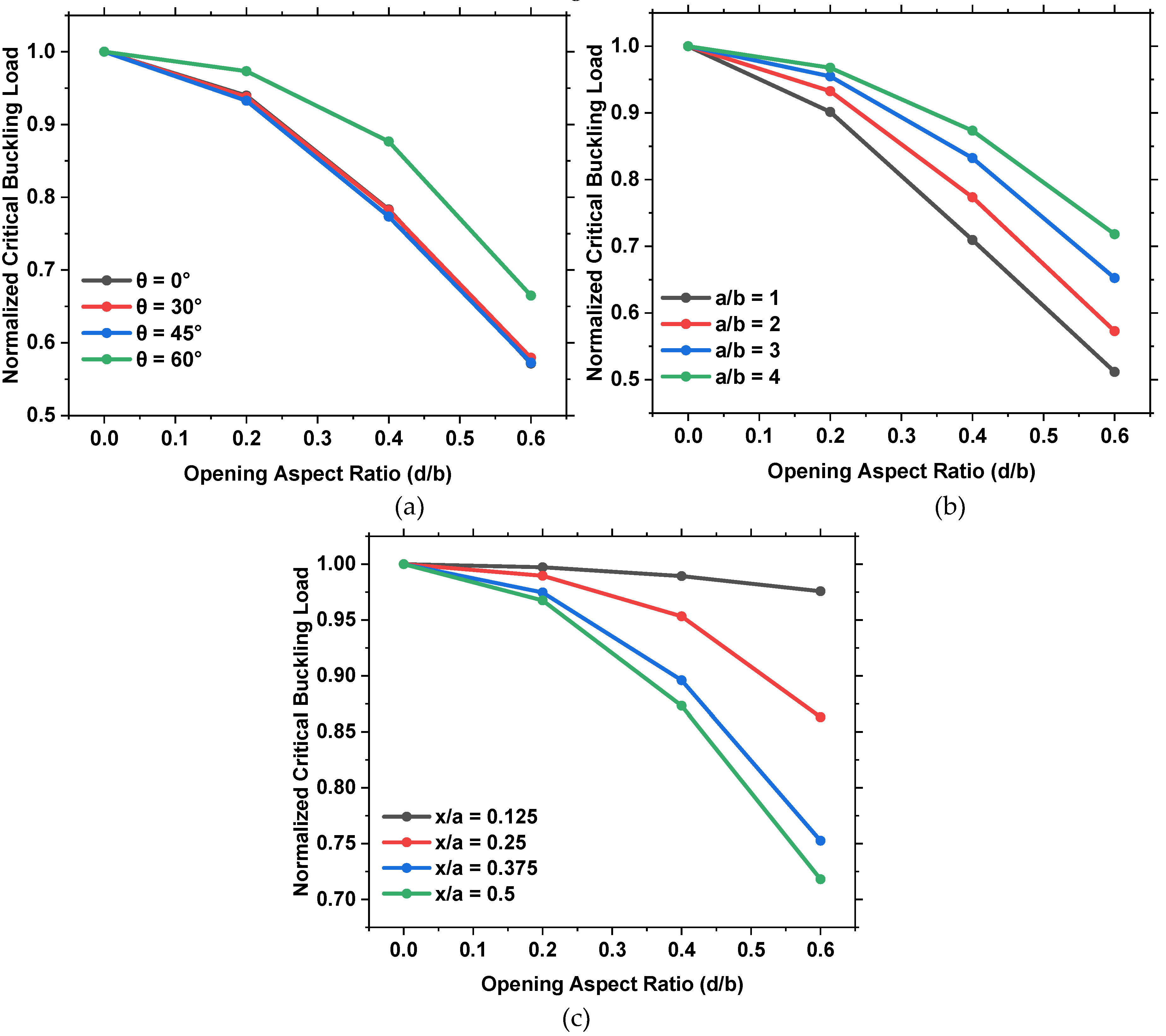
Figure 7.
The first four buckling modes of FGM plates with (a) no opening and 0 skew angle, (b) = 0.2 and 30 skew angle, (c) = 0.4 and 45 skew angle, (d) = 0.6 and 60 skew angle.
Figure 7.
The first four buckling modes of FGM plates with (a) no opening and 0 skew angle, (b) = 0.2 and 30 skew angle, (c) = 0.4 and 45 skew angle, (d) = 0.6 and 60 skew angle.
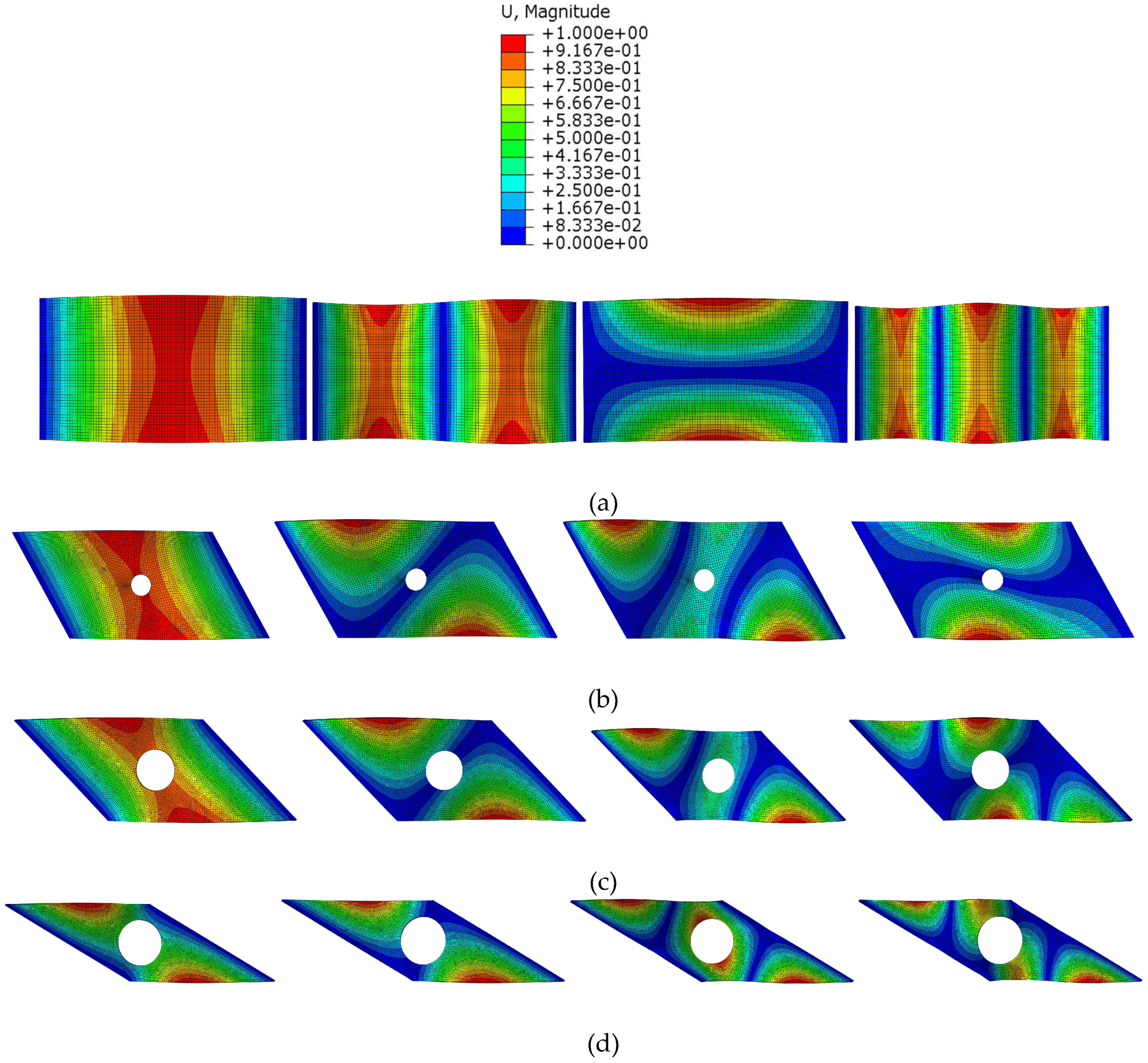
Figure 8.
The first four buckling modes of FGM plates with (a) no opening and an aspect ratio of 1(b) = 0.2 and an aspect ratio of 2 (c) = 0.4 and an aspect ratio of 3 (d) = 0.6 and an aspect ratio of 4.
Figure 8.
The first four buckling modes of FGM plates with (a) no opening and an aspect ratio of 1(b) = 0.2 and an aspect ratio of 2 (c) = 0.4 and an aspect ratio of 3 (d) = 0.6 and an aspect ratio of 4.
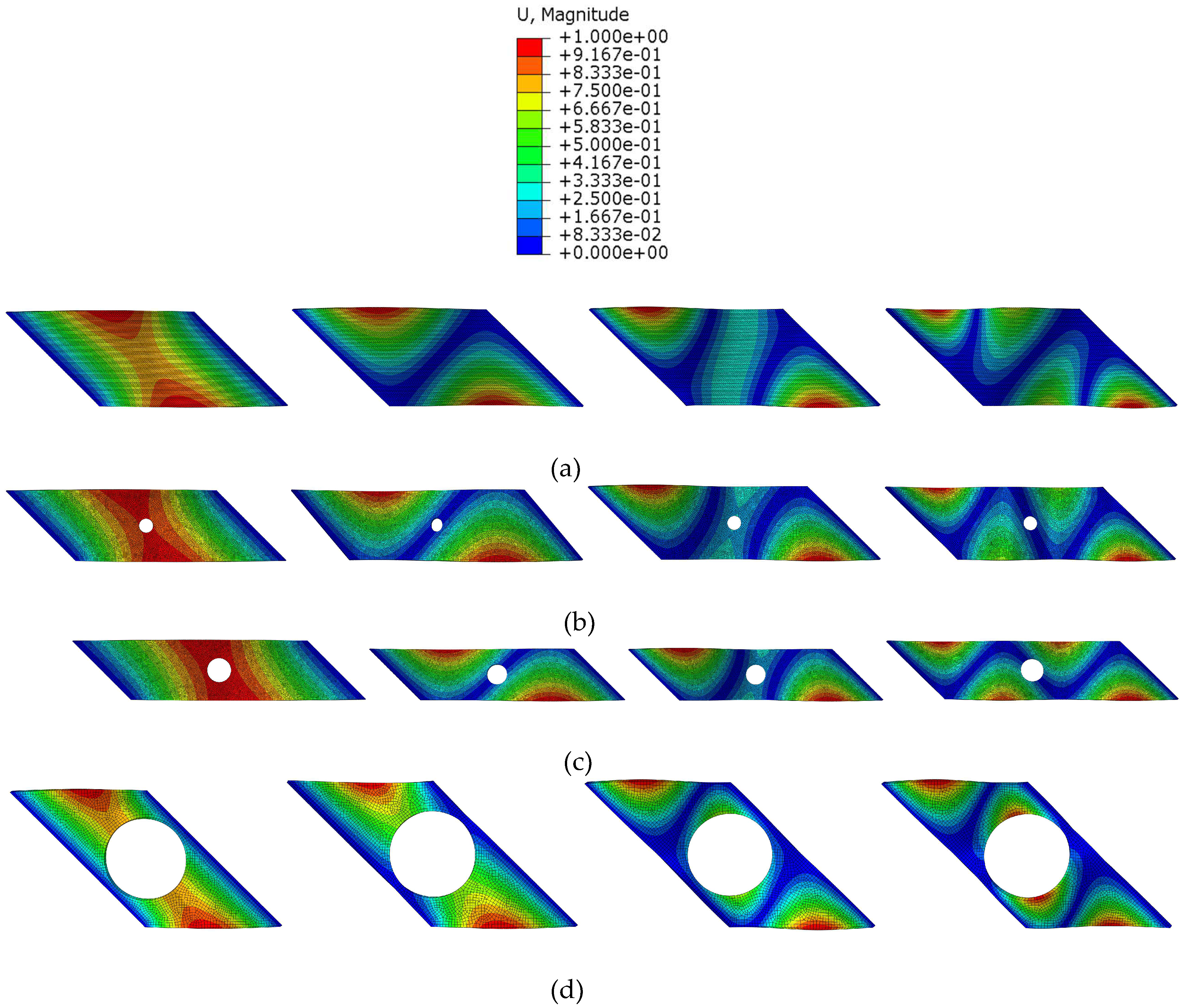
Figure 9.
The first four buckling modes of FGM plates with (a) no opening (b) = 0.2 and = 0.125 (c) = 0.4 and = 0.25 (d) = 0.6 and = 0.375 (e) = 0.4 and = 0.5 .
Figure 9.
The first four buckling modes of FGM plates with (a) no opening (b) = 0.2 and = 0.125 (c) = 0.4 and = 0.25 (d) = 0.6 and = 0.375 (e) = 0.4 and = 0.5 .
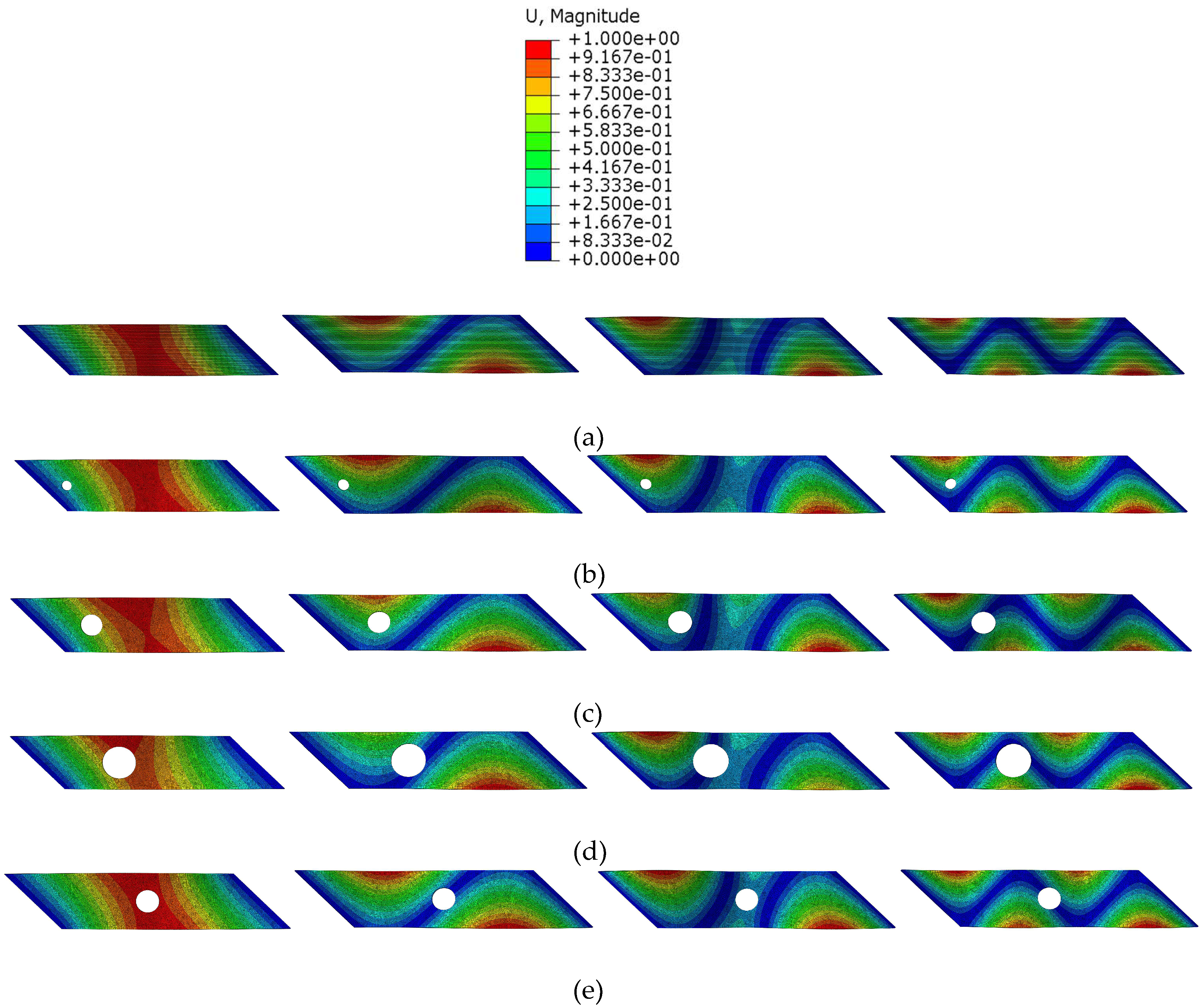

Table 1.
Critical Buckling Load for various skew angles and opening sizes.
| Aspect Ratio (a/b) |
Opening Position (x/a) |
Opening Size (d/b) |
Skew Angle () |
Critical Buckling Load (kN) |
|
|---|---|---|---|---|---|
| Control | 2 | 0 | 0 | 0 | 1652 |
| 30 | 2461 | ||||
| 45 | 4311 | ||||
| 60 | 8683 | ||||
| Small Opening | 2 | 0.5 | 0.2 | 0 | 1552 |
| 30 | 2308 | ||||
| 45 | 4021 | ||||
| 60 | 8450 | ||||
| Medium Opening | 2 | 0.5 | 0.4 | 0 | 1294 |
| 30 | 1926 | ||||
| 45 | 3335 | ||||
| 60 | 7613 | ||||
| Large Opening | 2 | 0.5 | 0.6 | 0 | 944 |
| 30 | 1426 | ||||
| 45 | 2469 | ||||
| 60 | 5772 |
Table 2.
Critical Buckling Load for various aspect ratios and opening sizes.
| Skew Angle () |
Opening Position (x/a) |
Opening Size (d/b) |
Aspect Ratio (a/b) |
Critical Buckling Load (kN) |
|
|---|---|---|---|---|---|
| Control | 45 | 0 | 0 | 1 | 19392 |
| 2 | 4311 | ||||
| 3 | 1728 | ||||
| 4 | 915 | ||||
| Small Opening | 45 | 0.5 | 0.2 | 1 | 17482 |
| 2 | 4021 | ||||
| 3 | 1650 | ||||
| 4 | 885 | ||||
| Medium Opening | 45 | 0.5 | 0.4 | 1 | 13758 |
| 2 | 3335 | ||||
| 3 | 1438 | ||||
| 4 | 799 | ||||
| Large Opening | 45 | 0.5 | 0.6 | 1 | 9922 |
| 2 | 2469 | ||||
| 3 | 1128 | ||||
| 4 | 657 |
Table 3.
Critical Buckling Load for various opening positions and sizes.
| Skew Angle () |
Aspect Ratio (a/b) |
Opening Size (d/b) |
Opening Position (x/a) |
Critical Buckling Load (kN) |
|
|---|---|---|---|---|---|
| Control | 45 | 4 | 0 | 0 | 915 |
| Small Opening | 45 | 4 | 0.2 | 0.125 | 913 |
| 0.250 | 905 | ||||
| 0.375 | 892 | ||||
| 0.500 | 885 | ||||
| Medium Opening | 45 | 4 | 0.4 | 0.125 | 905 |
| 0.250 | 872 | ||||
| 0.375 | 820 | ||||
| 0.500 | 799 | ||||
| Large Opening | 45 | 4 | 0.6 | 0.125 | 893 |
| 0.250 | 790 | ||||
| 0.375 | 689 | ||||
| 0.500 | 657 |
Disclaimer/Publisher’s Note: The statements, opinions and data contained in all publications are solely those of the individual author(s) and contributor(s) and not of MDPI and/or the editor(s). MDPI and/or the editor(s) disclaim responsibility for any injury to people or property resulting from any ideas, methods, instructions or products referred to in the content. |
© 2024 by the authors. Licensee MDPI, Basel, Switzerland. This article is an open access article distributed under the terms and conditions of the Creative Commons Attribution (CC BY) license (http://creativecommons.org/licenses/by/4.0/).
Copyright: This open access article is published under a Creative Commons CC BY 4.0 license, which permit the free download, distribution, and reuse, provided that the author and preprint are cited in any reuse.


