Submitted:
22 December 2023
Posted:
26 December 2023
You are already at the latest version
Abstract
Hydrogen storage in high pressure tanks can occur with different filling strategies. Many studies have been carried out on supplies with increasing pressure rates. However, hydrogen filling with constant mass inflow rate have not received the same attention. The present work aims to carry out numerical simulations to study hydrogen flow, in a type 3 tank of 70 MPa NWP and constant inflow rate condition. From the analysis of the results, it was possible to verify that there is a linear relationship between the increase in the total equilibrium temperature and the final hydrogen temperature. There is also a linear increasing relationship between Inlet and final temperatures when the equilibrium temperature is fixed. Considering fully adiabatic walls results in significant increases in temperature. The difference between total and static temperatures found in the Inlet tube decreases with the decrease in mass flow rate. The choice of a polymer for the tank lining led to higher temperatures when compared to an aluminum lining.
Keywords:
hydrogen filling
; hydrogen storage
; CFD Simulation
; hydrogen mobility
1. Introduction
The growing need to reduce greenhouse gas emissions has driven the search for new technologies with the capacity to supply and store large amounts of energy at competitive prices. At the current rate of fossil fuels use, it is expected that by 2050 their scarcity or economic unfeasibility of extraction will have a strong impact on the world economy [1]. An increase in energy consumption of 50% is predicted between 2018 and 2050, with renewable energy increasing by 3.1% per year, oil by 0.6% and natural gas by 1.1% [2]. Hydrogen currently represents just 0.03% of global energy production and 2% in Europe. Approximately 96% of this hydrogen is produced from natural gas and is mostly used to produce ammonia, plastics, hydrotreating processes in oil refineries and other chemical products [3].
To be competitive with current technologies, hydrogen supply must meet three goals [3]: low fueling time requirements, high safety and high filling rates.
To this extent, hydrogen supply at stations is carried out according to protocols developed by the Society of Automotive Engineers (SAE) to guarantee safety and maximum performance of the operation. SAE J2601 aims for rapid storage (3-5 minutes) of hydrogen in 35 and 70 MPa NWP tanks, up to a high state of charge (90 to 100% State of Charge -SOC) and without violating system temperature limits, pressure, and mass flow [4]. The established safety limits are: minimum hydrogen temperatures of - 40°C and maximum of 85°C, maximum pressure supplied 25% above the NWP, maximum mass flow of 0.060 kg.s-1. These limits prevent the integrity of the materials from being affected.
To ensure safety when filling a tank with hydrogen, it is important to know the phenomena responsible for the increase in temperature. The three most significant factors are: conversion of the gas's kinetic energy into internal energy, the Joule-Thomson effect and gas compression. The Joule-Thomson effect refers to the heating or cooling of a gas (or liquid) under the influence of large pressure gradients in an adiabatic and isenthalpic flow. This effect is typical in the presence of throttling valves and causes heating for gases with a negative Joule-Thomson coefficient [5], such as hydrogen.
Several studies have been carried out to evaluate the rapid supply of hydrogen. R. Hirotani et al. [6] demonstrated that tanks with materials with lower thermal conductivity, such as the polymer in type 4 tanks, result in higher temperatures. S.C. Kim et al. [7] found a greater occurrence of stratification in type 4 tanks and that this phenomenon significantly increased the maximum hydrogen temperature. Y. Zhao et al. [8] simulated several patterns of pressure increase and concluded that a linear pattern is the most suitable for obtaining lower final and maximum temperatures. Y.-L. Liu et al. [9] concluded that linear increases in initial pressures result in a linear decrease in maximum temperature. J. Zheng et al. [10] found that there is a linear relationship of temperature increase between the equilibrium temperature and final temperature. M. C. Galassi et al. [11] simulated a fully adiabatic tank and found that it resulted in significant increases in maximum and final temperature. N. de Miguel et al. [12] demonstrated that the increase in diameter and the decrease in mass flow rate caused the formation of stratification due to low velocities. N. R. Kesana et al. [13] modeled a tank with a high length-to-diameter ratio and found that, in this type of tank, buoyancy effects are significant. D. Melideo et al. [14] concluded that the drop in final temperature is approximately equal in magnitude to the same drop in pre-cooling temperature. Wang G et al. [15] determined that the final mass of hydrogen is inversely proportional to the mass flow rate and depends on heat transfer during fueling.
The present study aims to numerically analyze the rapid filling of hydrogen in a type 3 tank of 70 MPa NWP and constant mass flow rate as Inlet condition. The behavior of key variables such as temperature, pressure, velocity in different configurations of initial conditions will be evaluated. The CFD simulation results will be verified and validated with the results of D. Melideo et al. [16].
2. State of the art
2.1. Production
Currently most hydrogen is produced through methane steam reforming. As can be seen in Table 1, this method consists of a first reaction, endothermic, between methane and water at high temperatures and produces carbon monoxide and hydrogen. A second reaction, exothermic, occurs between the carbon monoxide resulting from the previous reaction and water vapor, producing carbon dioxide and hydrogen. It is common to use nickel-based catalysts due to their availability and low cost compared to those made from noble metals, however they have less activity and stability [17].
Methane pyrolysis consists of an endothermic reaction, with heat being used to separate the hydrogen and carbon molecules from methane. Unlike other processes, pyrolysis produces solid carbon and no carbon dioxide, which makes it attractive from an ecological point of view. Despite still not being able to compete economically with processes such as steam reforming, the practical applicability of solid carbon, such as in tires and agricultural products, and even greater logistical ease of storage when compared to carbon dioxide, offers great opportunities for growth to this technology. Currently this method is carried out through thermal decomposition, plasma decomposition or catalytic decomposition.
Electrolysis, on the other hand, produces hydrogen, using only water. Table 1 shows the reactions for a PEM cell. This cell has the anode and cathode separated by a polymer membrane, in which the flow of hydrogen protons occurs. Although electrolysis represents only 0.03% of hydrogen produced worldwide [18], it is expected to be one of the main forms of production in the future [19]. One of the advantages of this method is the high purity of the hydrogen produced, higher than 99.95%.
Depending on the production method, hydrogen can be considered more or less ecological, for that reason color codes were developed for its classification, as can be seen in Table 2.
2.2. Storage
Hydrogen can be stored in solid, liquid or gaseous state. The most common method, especially for storage in light or heavy vehicles, is in gaseous state. Due to its low density, it is necessary to compress hydrogen to high pressures. Table 3 presents the types of tanks currently available, as well as their construction materials, cost and properties.
The type 1 tank has an all-metal construction, normally steel, which results in low production costs but high weight. For this reason, it is generally used as a stationary tank to store hydrogen in refueling stations or industrial use. It operates at pressures between 17.5 and 20 MPa [24].
The type 2 tank has a metallic construction like type 1, but the addition of a carbon fiber hoop wrapping in the tank results in higher NWP values, between 26.3 and 30 MPa.
Type 3 and 4 tanks are light and withstand high pressures due to their full carbon fiber wrapping, making them expensive. The lining is composed of aluminum for type 3 and polymer for type 4. Aluminum, despite making the tank heavier and less resistant to fatigue than the polymer, provides much lower permeability to hydrogen. Both are preferred for vehicle storage and operate at 35 and 70 MPa NWP [25].
Liquid hydrogen storage can be done with several liquefaction methods, the simplest being the Linde cycle, also called the Joule-Thomson expansion cycle. Initially, the gas is compressed using a compressor and cooled with a heat exchanger; then it passes through a throttling valve and cools owing to the Joule-Thomson expansion effect. Some liquid is produced and stored while the gas returns to the compressor. Liquefaction, compared to gaseous storage, has a very high economic and energy cost [26].
The so-called solid hydrogen storage is based on the hydrogen ability to react with some metallic alloys, say M, as titanium, manganese, chromium and nickel, producing a metallic species, MH2, according to M + H2 → M H2 [27-29]. This avoids the disadvantages related with weight and safety of hydrogen gaseous storage and the high energy needs linked with the liquid state. However, it requires high reservoir volumes and filling time, which for a 5 kg tank of hydrogen is on the order of one hour while in a gaseous state it is around 3 to 5 minutes [30].
3. Simulations CFD
3.1. Cases studied
The simulations carried out are found in Table 4, divided into 8 categories to which a case corresponds.
This work uses the 40 liter, 70 MPa type 3 tank (NWP) from the article by D. Melideo et al. [16], for all simulations, as well as their experimental results for the validation, Case 1, of the CFD model [31]. The results will also be compared between the Standard K – ε turbulence model in Case 1 and the Realizable K – ε model in Case 2.
In Cases 3 and 4, the temperature was successively increased by 10 K. An initial condition of thermal equilibrium between the tank, environment and the supplied hydrogen was assumed for Case 3, and a fixed initial temperature (279.2 K) for Case 4.
Velocity is a highly important parameter in evaluating the flow behavior and temperatures of hydrogen. As it is interconnected with the mass flow rate, in Case 6, different mass flow rates were tested and their impact analyzed.
To analyze the influence on temperature associated with the fully adiabatic case, a mesh without lining and coating was constructed and two sets of simulations were carried out, Cases 5 and 7, with initial conditions equal to non-adiabatic cases 3 and 6 respectively.
Finally, in Case 8, a type 4 tank with a high-density polyethylene polymer (HDPE) lining was simulated, with the same dimensions as type 3 and flow conditions of Case 4-C.
The Ansys Fluent® 2023 R2 was used as simulation software. Due to the high computational cost, only 50 seconds were simulated in each case.
After carrying out Time-Step independence tests with values of 0.005, 0.002 and 0.001 seconds, a conservative decision was made to use a Time-Step of 0.002 seconds in all simulations.
The initial pressure value in all simulations was 2 MPa.
3.2. Preprocessing settings
The geometry, Figure 1, is composed of a cylinder and two half spheres, with dimensions according to Table 5. It was necessary to modify the interior length of the tank due to the lack of information on the exact geometry of the concave areas. The length was changed so that the resulting volume was 40 liters. Due to the high computational cost of a 3D simulation, it was decided to carry out a 2D simulation. The construction of the 2D geometry was carried out by establishing the X axis as the axis of axial symmetry. The Inlet tube has an internal diameter of 3 mm and a thickness of 2 mm.
The physical properties of the materials for type 3 and 4 tanks used can be found in [32].
For hydrogen, specific heat (Cp), thermal conductivity and dynamic viscosity were established as fourth degree polynomial functions [33].
The calculation of the density of hydrogen is done using the equation of state. Due to the high pressures that occur during filling a real gas equation is indicated. For filling a tank with hydrogen, it was observed that the equation with the best results was the Redliche-Kwong [34], given by equation (1).
where Vm is the mole volume, R the universal gas constant with value 8.314 J.mol-1.k-1, T the temperature, and a and b correction constants for the molecular and volumetric attractive potential respectively. These constants are calculated at the critical pressure pc and critical temperature Tc [35], according to equations (2).
Three meshes were constructed for mesh independence verification tests and one (Mesh 4) for the adiabatic cases. The model used (except Case 2) was the Standard K – ε. It is a popular, robust model, with relatively low computational cost and which has shown good results, according to several authors, [5], [8], [16], as well as in the current validation process. It was necessary to modify the C1 constant from 1.44 to 1.52 due to a high propagation rate of the hydrogen jet, found in this model by [36]. The Realizable K – ε model differs from the Standard in the formulation of the equation for turbulent dissipation rate and in Cμ,, which becomes a variable as opposed to a constant in the Standard.
Due to the compression of the gas in the tank, heating by viscous forces cannot be considered negligible, which is why viscous heating (Viscous Heating) was activated [33].
Figure 1 illustrates the computational mesh, structured and non-adaptive of 26522 cells, resulting from the mesh independence tests.
As the Inlet tube is adiabatic, its mesh was not constructed. For the adiabatic cases (5 and 7) the outer surface has a condition of zero heat flux (adiabatic). For the remaining cases, a convection condition was established with the value of the heat transfer coefficient equal to 6 W.m-2.K-1 [16].
3.3. Solver settings
A summary of the parameters used for the solver, in this work, is presented in Table 6.
To achieve smoothness the value of 10-4 was assumed as the general convergence criterion and the value of 10-6 for the energy equation.
3.4. Validation
In general, the validation showed good results. As in the simulation made by D. Melideo et al. [16] there is a small overestimation of the temperatures of the gas, Figure 2, and aluminum, Figure 3, in relation to the experiment. Adding the fact that the temperature increase profile follows very closely that of [16], it's possible to conclude that the choices made in Preprocessing and Solver were correct.
The difference between simulations and experience may be explained by the effects produced by opening the valve at the beginning of filling. As with [16], also in this work, higher temperatures were found in the tank materials on the side opposite to the Inlet Figure 4. This is due to several factors, such as the effects of compression being felt more in this area and an even higher coefficient of heat transfer resulting from higher velocities.
The Realizable model in Case 2 closely followed the Standard results, as can be seen in Table 7. However, as it presented a relatively small overestimation in temperature values, the Standard model was chosen for the remaining simulations.
The difference between maximum pressure (Inlet) and minimum pressure (inside the tank) throughout the filling simulations was also analyzed to verify the impact of the Joule-Thomson effect. The effect is responsible for increasing the hydrogen temperature from 2.64°C to 5.05°C for a pressure difference of 10 MPa [38,39]. In the current cases, the maximum difference measured was 0.19 MPa, so this effect is negligible in the current study. This is due to the fact that in the simulation It was only considered the flow after the Inlet, and in this position the pressure variation between tank and Inlet is small, decreasing even further as filling progresses [40].
4. Results
4.1 Increase of temperatures in total equilibrium with environment
In a situation of initial equilibrium between the temperature of the hydrogen, tank materials, exterior (convention condition) and the Inlet, Case 3, a 10 K increase in the initial temperatures (total equilibrium) resulted in an increase in the average hydrogen final temperature of 11 K, as shown in Figure 5. This value is close to the 10 K found by J. Zheng et al. [10] in a simulation of a type 3 tank of 70 MPa and with variable pressure conditions in the Inlet. The discrepancy between values may be due to the properties of the tank materials, different volume (74 liters) or the Inlet pressure condition. However, it is possible to conclude that these three factors will not significantly influence the value of the linear increase in hydrogen temperature in this type of tanks.
As can be seen in Figure 5, the temperature of the aluminum lining also increased linearly with the same value of 11 K, despite a different growth profile. The temperature difference between hydrogen and aluminum was approximately 10 to 12 K.
The increase in the initial equilibrium temperature and consecutively lower density of hydrogen results in linear increases in the final pressure, initial velocity and final velocity, according to Table 8.
4.2. Increase of temperature of Inlet with equilibrium temperature set
In Case 4, the initial temperature of the tank and hydrogen was set at 279.2 K (arbitrary value to simulate a situation of lower temperatures due to the decompression of hydrogen during consumption) and that of the Inlet and exterior was increased by 10 K.
As in Case 3, a linearity relationship was found in the average gas temperature. In this case, as shown in Figure 6, the rise was 4.5 K for every 10 increases. As in the previous case, the aluminum lining also increased linearly with the same value of the average temperature.
4.3. Influence of mass flow variation on Inlet velocity and temperature
As expected, the decrease in mass flow results in a decrease in velocity [12], however it was found that there is convergence of speeds over time, Figure 7.
The hydrogen velocity also has a significant influence on the static temperature T in the Inlet tube area. This happens because in the mass flow Inlet boundary condition the imposed temperature is the total T_0, according to equation (3) of isentropic flow.
being the ratio of specific heat at constant pressure Cp and of specific heat at constant volume CV. The Mach number, , is given by (4).
with V the local speed and a the speed of sound [41]. As the flow of a liquid can be considered incompressible, due to its low variation in density, in a gas this assumption is more restricted. The flow of a gas is considered incompressible if its Mach value is less than 0.3 and compressible otherwise [42]. In the compressible range, it is considered subsonic up to values of 1 and supersonic from 1 to 5. As the Mach number increases, the compressive effects become more evident, especially in the density above a Mach value equal to 1.
As shown in Figure 8, some of the tested cases had Mach values greater than 0.3. This is the reason why the static temperatures at the Inlet and along the pipe differ from those defined in total temperature Inlet condition. As the flow in the Inlet has compressible Mach, the static temperature in this zone is lower than the total.
As the supply time progresses, the static Inlet temperature will converge with the total temperature.
An important aspect of this is that, depending on the measuring point in the tank, the choice of the type of temperature sensor can make a difference. Now, to comply with the Inlet condition, the sensor should measure the total temperature, but so far, to our knowledge, such information does not exist.
4.4. Adiabatic tank
An increase of 10 K in each simulation resulted in a sharp, non-linear rise in temperature in Cases 5 and 7. The difference in temperatures between the adiabatic cases 5 and 7 and the respective non-adiabatic cases are presented in Table 9 and Table 10.
It can be verified when materials are removed from the tank there is a drastic rise in temperature. This occurs because aluminum begins to absorb and conduct heat from hydrogen from the beginning, thus reducing its temperature. The results demonstrate that considering a fully adiabatic tank leads to a high temperature overestimation. Similar conclusion was drawn by [38,39].
Unlike the respective non-adiabatic cases, Cases 5 and 7 did not show hydrogen homogeneity within the tank. As can be seen in Figure 9, there are visibly higher temperatures in the left area than in the rest of the tank. The reason for the above may be related to the low velocity, which entail low mixing with the remaining gas.
4.5. Tank type 4
As expected, the hydrogen temperatures of a type 4 tank compared to type 3 are higher, Figure 10. This is due to the fact that the HDPE liner has lower thermal conductivity than aluminum. Unlike cases 3 and 4, here the difference between the gas temperatures is not of the same magnitude as that of the lining. The difference between hydrogen temperatures at 50 seconds was greater than 20 K and that of the lining did not reach 5 K, being the reason again the low conductivity of HDPE compared to aluminum.
Figure 11 shows that the hydrogen pressure in tank 4 began to increase more quickly as filling progressed. However, the velocity did not present this behavior and closely followed the speed profile of the type 3 tank, with a maximum difference of 20 m.s-1 at 10 seconds.
5. Conclusions
The objective of this study was the numerical analysis of a tank filling process with hydrogen at constant mass flow rate, through a set of CDF simulations with different initial conditions and properties. From the results it was possible to conclude that:
- Realizable Model presented results close to the Standard.
- Linear relationships of temperature increase were verified, both for tanks in total initial thermal equilibrium with the environment, and with a fixed initial temperature. An increase of 10 K resulted, in Case 3, in an increase of 11 K in the average temperature and in Case 4, in an increase of 4.5 K.
- Due to the compressive nature of the flow, the variation in mass flow rate and, consequently, in velocity has significant implications for temperatures along the Inlet tube. As the speed increases, the difference between static and total temperature increases and the static temperature decreases.
- Adiabatic tanks cause temperature increases in the order of 50 to 60 K for the first 50 seconds of simulation.
- The comparison between a type 3 and 4 tank, with the same conditions except for the lining, demonstrated that the increase in temperature in the type 4 tank begins to be significant at around 3 seconds and stabilizes at around 30. The pressure is also greatly affected while the temperature did not show relevant differences.
- It was also found that the Joule-Thomson effect is negligible for current cases.
Author Contributions
J.M.M.: Investigation, writing—original draft preparation, software; L.R.: Conceptualization, Supervision, Writing—review and editing; G.F.P.: Supervision, Writing—review and editing, software, validation; J.M.: Writing—review, A.B. Formal analysis, software, validation, Project administration. All authors have read and agreed to the published version of the manuscript.
Funding
This research received no external funding.
Data Availability Statement
Not applicable.
Acknowledgments
Not applicable.
Conflicts of Interest
The authors declare no conflict of interest.
Abbreviations
| Acronyms | ||
| NWP | Normal working pressure | |
| SAE | Society of automotive engineers | |
| SOC | State of charge | |
| CFD | Computational fluid dynamics | |
| PEM | Proton exchange membrane | |
| s | Solid | |
| e | Electron | |
| UDF | User defined function | |
| HDPE | High density polyethylene | |
| 2D, 3D | Two-Dimensional, Three-Dimensional | |
| Cp | specific heat at constant pressure | |
| p | Pressure | |
| T | Temperature | |
| R | Universal gas constant of a perfect gas | |
| V | Volume | |
| a,b | Constants to correct for the attractive potential of molecules and volume | |
| e | Turbulent dissipation rate | |
| C_μ,C1 | Constants | |
| REF | Reference paper for validation | |
| M | Mach number | |
| γ | Specific heat ratio | |
| V | Local velocity | |
| a | Speed of sound | |
| Subscripts | ||
| m | Molar | |
| c | Critical | |
| 0 | Total | |
References
- Hall, C. A. S.; and Klitgaard, K. A. Energy and the Wealth of Nations., 2nd ed.; Springer: New York, New York, 2012. [Google Scholar]
- “International Energy Outlook 2019,” Energy Information Administration. Office of Energy Analysis U.S. Department of Energy. Washington, DC 20585, 2019.
- Dawood, F.; Anda, M.; and Shafiullah, G. M. Hydrogen production for energy: An overview. Int J Hydrogen Energy 2020, 7, 3847–3869. [Google Scholar] [CrossRef]
- Schneider, J.; Meadows, G.; Mathison, S.; Veenstra, M.; Shim, J.; Immel, R.; Wistoft-Ibsen, M.; Quong, S.; Greisel, M.; McGuire, T.; and Potzel, P. Validation and Sensitivity Studies for SAE J2601, the Light Duty Vehicle Hydrogen Fueling Standard. SAE International Journal of Alternative Powertrains 2014, 53. [Google Scholar] [CrossRef]
- Suryan, A.; Kim, H. D.; and Setoguchi, T. Comparative study of turbulence models performance for refueling of compressed hydrogen tanks. Int J Hydrogen Energy 2013, 22, 9562–9569. [Google Scholar] [CrossRef]
- Hirotani, R.; Terada, T.; Tamura, Y.; Mitsuishi, H.; and Watanabe, S. Thermal Behavior in Hydrogen Storage Tank for Fuel Cell Vehicle on Fast Filling. Japan Automobile Research Institute 2007, 10. [Google Scholar]
- Kim, S. C.; Lee, S. H.; and Yoon, K. B. Thermal characteristics during hydrogen fueling process of type IV cylinder. Int J Hydrogen Energy 2010, 13, 6830–6835. [Google Scholar] [CrossRef]
- Zhao, Y.; Liu, G.; Liu, Y.; Zheng, J.; Chen, Y.; Zhao, L.; Guo, J.; and He, Y. Numerical study on fast filling of 70 MPa type III cylinder for hydrogen vehicle. Int J Hydrogen Energy 2012, 22, 17517–17522. [Google Scholar] [CrossRef]
- Liu, Y.-L.; Zhao, Y.-Z.; Zhao, L.; Li, X.; Chen, H.-G.; Zhang, L.-F.; Zhao, H.; Sheng, R.-H.; Xie, T.; Hu, D.-H; and Zheng, J.-Y. Experimental studies on temperature rise within a hydrogen cylinder during refueling. Int J Hydrogen Energy 2010, 7, 2627–2632. [Google Scholar] [CrossRef]
- Zheng, J.; Guo, j.; Yang, J.; Zhao, Y.; Zhao, L.; Pan, X.; Ma, J.; and Zhang, L. Experimental and numerical study on temperature rise within a 70 MPa type III cylinder during fast refueling. Int J Hydrogen Energy 2013, 25, 10956–10962. [Google Scholar] [CrossRef]
- Galassi, M. C.; Baraldi, D.; Iborra, B. A.; and Moretto, P. CFD analysis of fast filling scenarios for 70 MPa hydrogen type IV tanks. Int J Hydrogen Energy 2012, 8, 6886–6892. [Google Scholar] [CrossRef]
- Miguel, N.; Acosta, B.; Moretto, P.; and Cebolla, R. O. Influence of the gas injector configuration on the temperature evolution during refueling of on-board hydrogen tanks. Int J Hydrogen Energy 2016, 42, 19447–19454. [Google Scholar] [CrossRef]
- Kesana, N. R.; Welahettige, P.; Hansen, P. M.; Ulleberg, Ø.; and Vågsæther, K. Modelling of fast fueling of pressurized hydrogen tanks for maritime applications. Int J Hydrogen Energy 2023, 79, 30804–30817. [Google Scholar] [CrossRef]
- Melideo, D.; Baraldi, D.; Galassi, M. C.; Cebolla, R. O.; Iborra, B. A.; and Moretto, P. CFD model performance benchmark of fast filling simulations of hydrogen tanks with pre-cooling. Int J Hydrogen Energy 2014, 9, 4389–4395. [Google Scholar] [CrossRef]
- Wang, G.; Zhou, J.; Hu, S.; Dong, S.; and Wei, P. Investigations of filling mass with the dependence of heat transfer during fast filling of hydrogen cylinders. Int J Hydrogen Energy 2014, 9, 4380–4388. [Google Scholar] [CrossRef]
- Melideo, D.; Baraldi, D.; Iborra, B. A; Cebolla, R. O.; and Moretto, P. CFD simulations of filling and emptying of hydrogen tanks. Int J Hydrogen Energy 2017, 11, 7304–7313. [Google Scholar] [CrossRef]
- Bastardo, N. S.; Schlögl, R.; and Ruland, H. Methane Pyrolysis for Zero-Emission Hydrogen Production: A Potential Bridge Technology from Fossil Fuels to a Renewable and Sustainable Hydrogen Economy. Ind Eng Chem Res 2021, 32, 11855–11881. [Google Scholar] [CrossRef]
- IEA, International Energy Agency “Hydrogen review 2021,” 2021.
- Martino, M.; Ruocco, C.; Meloni, E.; Pullumbi, P.; and Palma, V. Main Hydrogen Production Processes: An Overview. Catalysts 2021, 5, 547. [Google Scholar] [CrossRef]
- Ajanovic, A.; Sayer, M.; and Haas, R. The economics and the environmental benignity of different colors of hydrogen. Int J Hydrogen Energy 2022, 57, 24136–24154. [Google Scholar] [CrossRef]
- Noussan, M.; Raimondi, P. P.; Scita, R.; and Hafner, M. The Role of Green and Blue Hydrogen in the Energy Transition—A Technological and Geopolitical Perspective. Sustainability 2020, 1, 298. [Google Scholar] [CrossRef]
- IEA (2019), The Future of Hydrogen: Seizing today’s opportunities, OECD, Paris Cedex 16. IEA, 2019.
- Kim, S. C.; Lee, S. H.; and Yoon, K. B. Thermal characteristics during hydrogen fueling process of type IV cylinder. Int J Hydrogen Energy 2010, 13, 6830–6835. [Google Scholar] [CrossRef]
- Li, M.; Bai, Y.; Zhang, C.; Song, Y.; Jiang, S.; Grouset, D.; and Zhang, M. Review on the research of hydrogen storage system fast refueling in fuel cell vehicle. Int J Hydrogen Energy 2019, 21, 10677–10693. [Google Scholar] [CrossRef]
- Su, Y.; Lv, H.; Zhou, W.; and Zhang, C. Review of the Hydrogen Permeability of the Liner Material of Type IV On-Board Hydrogen Storage Tank. World Electric Vehicle Journal 2021, 3, 130. [Google Scholar] [CrossRef]
- Allevi, C.; and Collodi, G. Hydrogen production in IGCC systems. Integrated Gasification Combined Cycle (IGCC) Technologies, Elsevier 2017, 419–443.
- Baptista, A.; Pinho, C.; Pinto, G.; Ribeiro, L.; Monteiro, J.; Santos, T. Assessment of an Innovative Way to Store Hydrogen in Vehicles. Energies 2019, 12, 1762. [Google Scholar] [CrossRef]
- Pinto, G.; Monteiro, J.; Baptista, A.; Ribeiro, L.; Leite, J. Study of the Permeation Flowrate of an Innovative Way to Store Hydrogen in Vehicles. Energies 2021, 14, 6299. [Google Scholar] [CrossRef]
- Ribeiro, L.; Pinto, G.F.; Baptista, A.; Monteiro, J. Study on a New Hydrogen Storage System – Performance, Permeation, and Filling/Refilling. Hydrogen Electrical Vehicles, 1st ed., Sankir, M., Sankir, N.; Scrivener Publishing LLC 2023, Vol. 1, pp 11-46.
- Prabhukhot, P. R.; Wagh, M. M.; and Gangal, A. C. A Review on Solid State Hydrogen Storage Material. Advances in Energy and Power 2016, 2, 11–22. [Google Scholar]
- “Guide: Guide for the Verification and Validation of Computational Fluid Dynamics Simulations (AIAA G-077-1998(2002)),” in Guide: Guide for the Verification and Validation of Computational Fluid Dynamics Simulations (AIAA G-077-1998(2002)), Washington, DC: American Institute of Aeronautics and Astronautics, Inc., 1998.
- Miguel, N.; Cebolla, R. O.; Acosta, B.; Moretto, P.; Harskamp, F. and Bonato, C. Compressed hydrogen tanks for on-board application: Thermal behaviour during cycling. Int J Hydrogen Energy 2015, 19, 6449–6458. [Google Scholar] [CrossRef]
- Suryan, A.; Kim, H. D.; and Setoguchi, T. Three dimensional numerical computations on the fast filling of a hydrogen tank under different conditions. Int J Hydrogen Energy 2012, 9, 7600–7611. [Google Scholar] [CrossRef]
- Nasrifar, K. Comparative study of eleven equations of state in predicting the thermodynamic properties of hydrogen. Int J Hydrogen Energy 2010, 8, 3802–3811. [Google Scholar] [CrossRef]
- Kim, M.-S.; Ryu, J.-H.; Oh, S.-J.; Yang, J.-H.; and Choi, S.-W. Numerical Investigation on Influence of Gas and Turbulence Model for Type III Hydrogen Tank under Discharge Condition. Energies (Basel) 2020, 23, 6432. [Google Scholar] [CrossRef]
- Magi, V. I. J. A. V. The k-ε Model and computed spreading rates in round and plate jets. Numeri Heat Transf A Appl 2001, 4, 317–334. [Google Scholar]
- Setoguchi, T.; Alam, M. M. A.; Monde, M.; and Kim, H. D. Characteristics of Turbulent Confined Jets during Fast Filling of H 2 Tank at High Pressure. Int J Aeroacoust 2013, 5–6, 455–474. [Google Scholar] [CrossRef]
- Galassi, M. C.; Papanikolaou, E.; Heitsch, M.; Baraldi, D.; Iborra, B. A.; and Moretto, P. Assessment of CFD models for hydrogen fast filling simulations. Int J Hydrogen Energy 2014, 11, 6252–6260. [Google Scholar] [CrossRef]
- Miguel, N.; Acosta, B.; Baraldi, D.; Melideo, R.; Cebolla, R. O.; and Moretto, P. ; The role of initial tank temperature on refuelling of on-board hydrogen tanks. Int J Hydrogen Energy 2016, 20, 8606–8615. [Google Scholar] [CrossRef]
- Acosta, B.; Moretto, P.; Miguel, N.; Ortiz, R.; Harskamp, F.; and Bonato, C. JRC reference data from experiments of on-board hydrogen tanks fast filling. Int J Hydrogen Energy 2014, 35, 20531–20537. [Google Scholar] [CrossRef]
- Glenn Research Center, “Speed of sound,” Nasa. Nasa, 2021. https://www.grc.nasa.gov/www/BGH/snddrv.html (accessed on 14 June 2023).
- Ansys, “ANSYS Fluent theory guide,” Ansys Fluent. Ansys, 2022.
Figure 1.
Computational mesh.
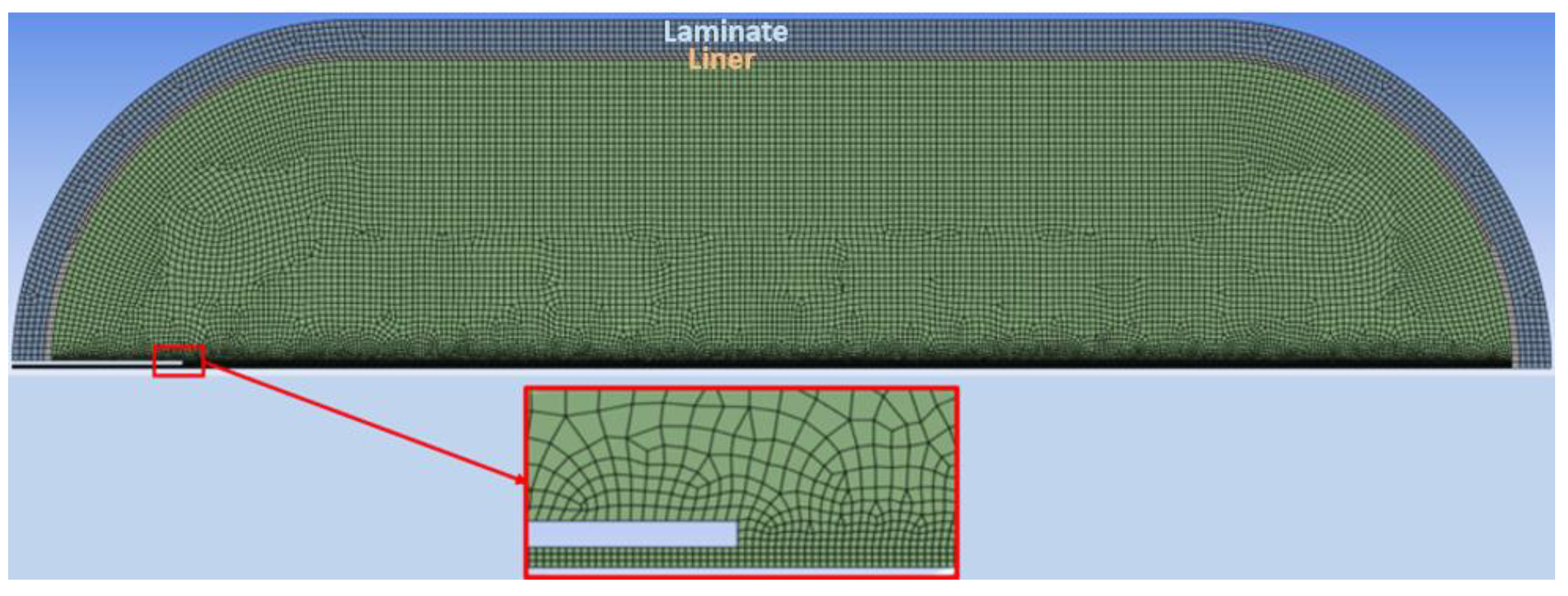
Figure 2.
Comparison of hydrogen temperature results with REF D. Melideo et al. [16].
Figure 2.
Comparison of hydrogen temperature results with REF D. Melideo et al. [16].
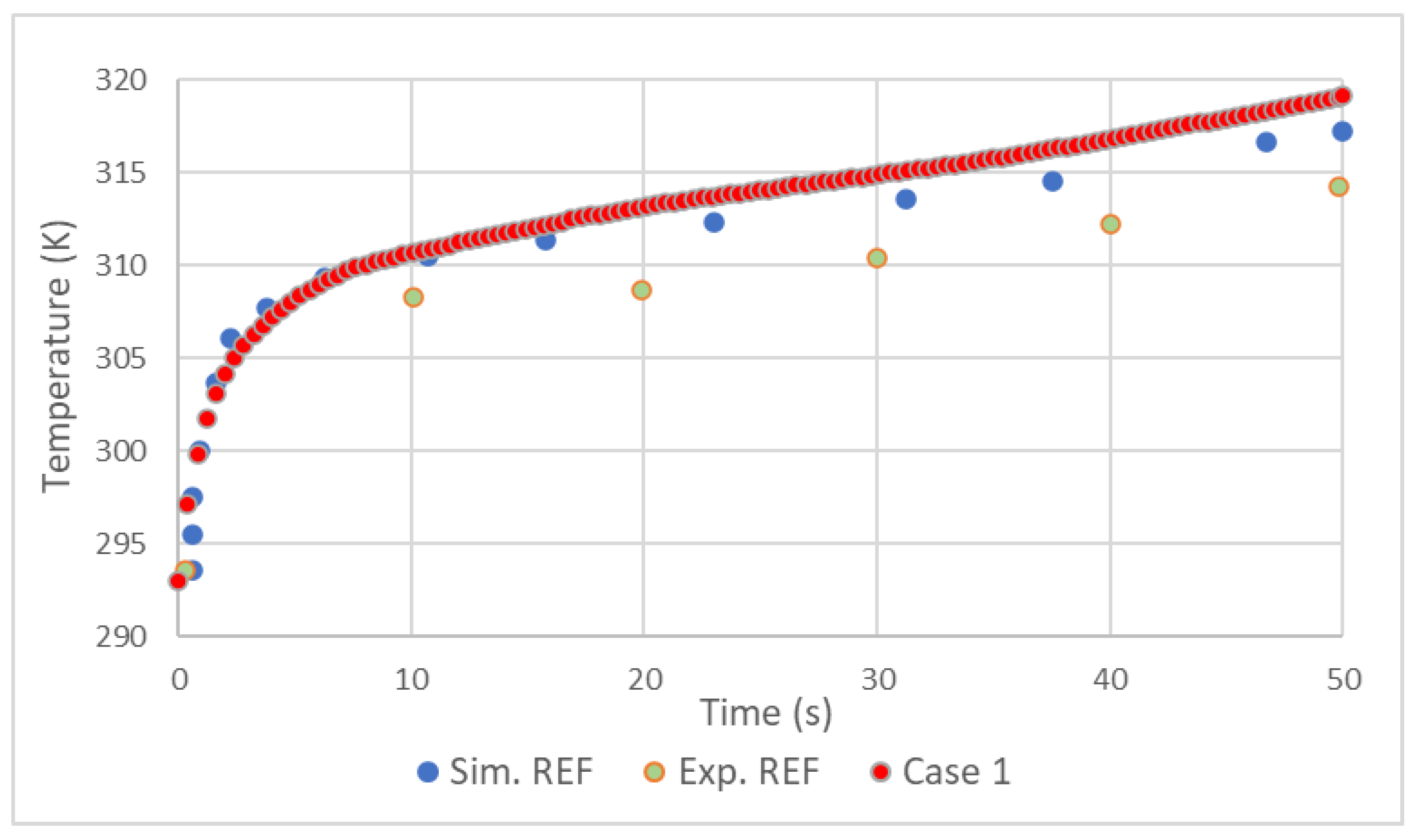
Figure 3.
Comparison of aluminum liner temperature results with REF D. Melideo et al. [16].
Figure 3.
Comparison of aluminum liner temperature results with REF D. Melideo et al. [16].
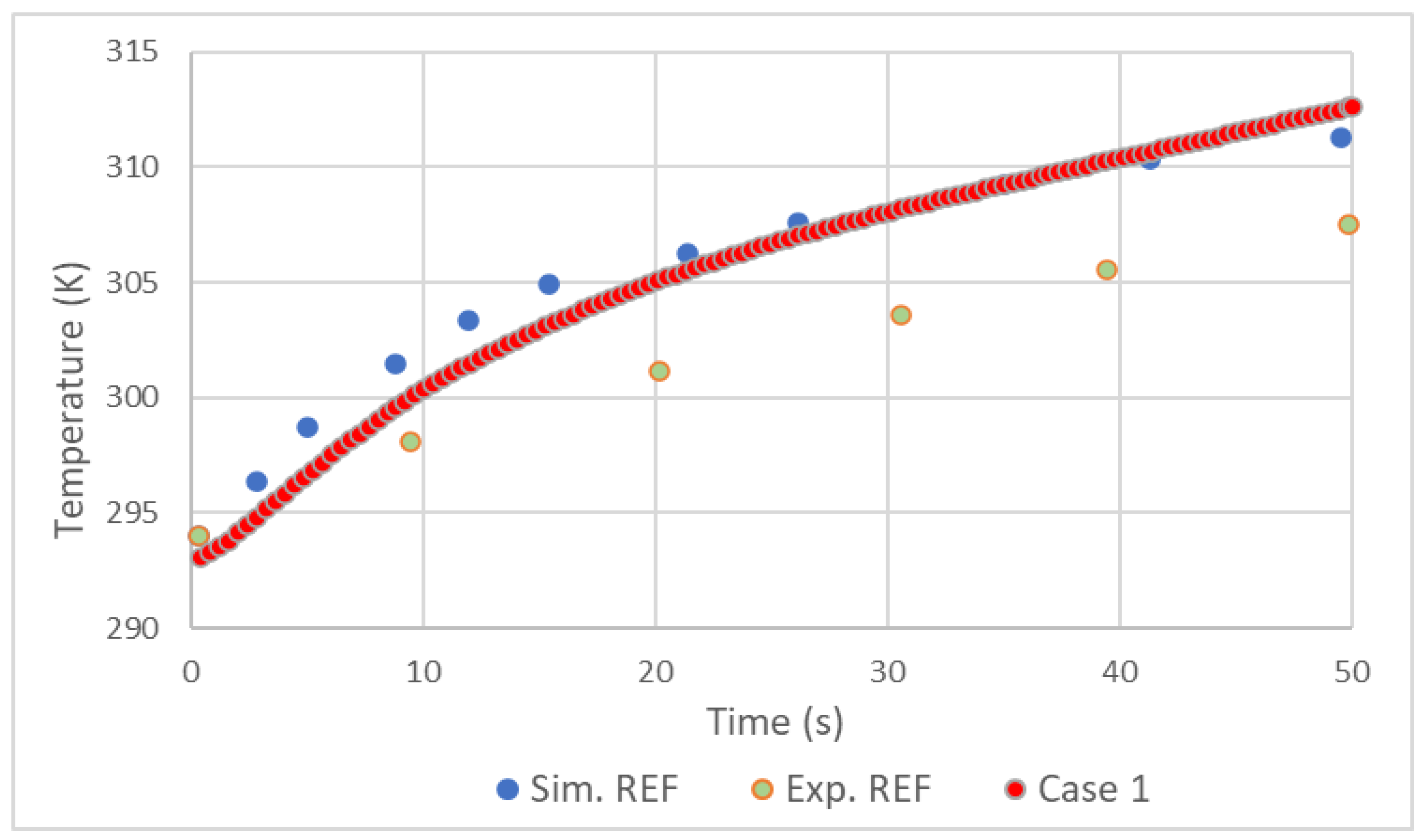
Figure 4.
Temperatures of aluminum liner (a) and whole tank (b).
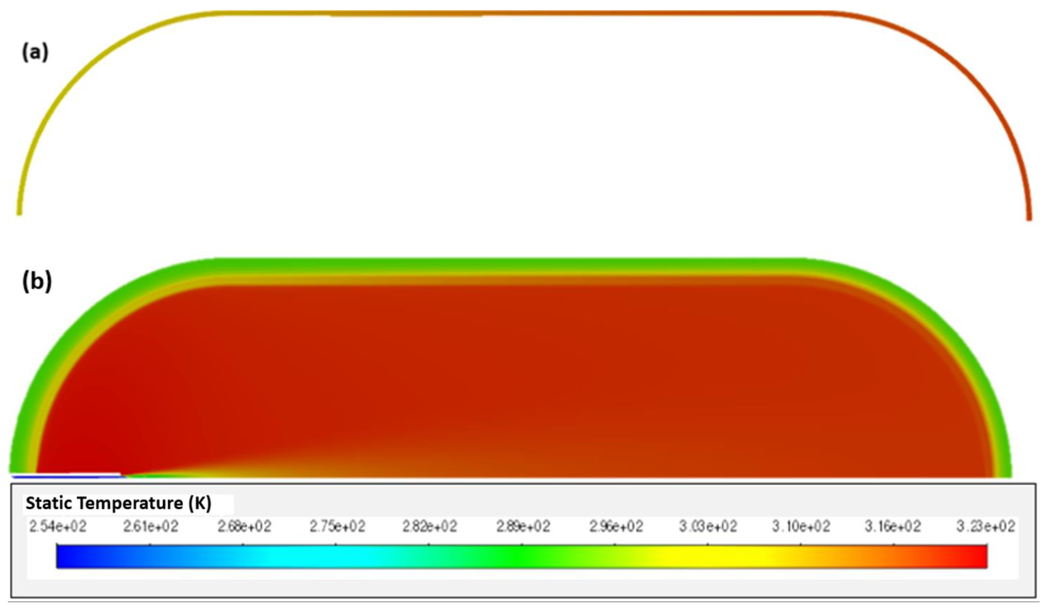
Figure 5.
Hydrogen and aluminum liner temperature history for Case 3.
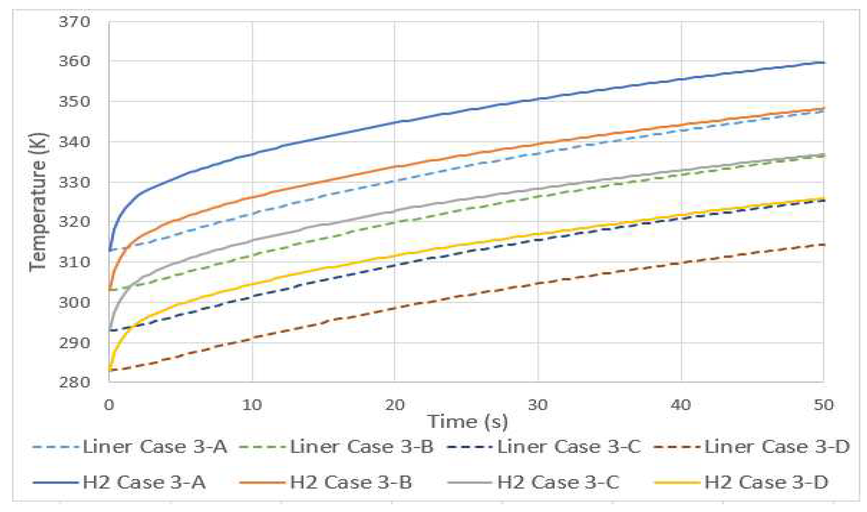
Figure 6.
Hydrogen and aluminum liner temperature history for Case 4.
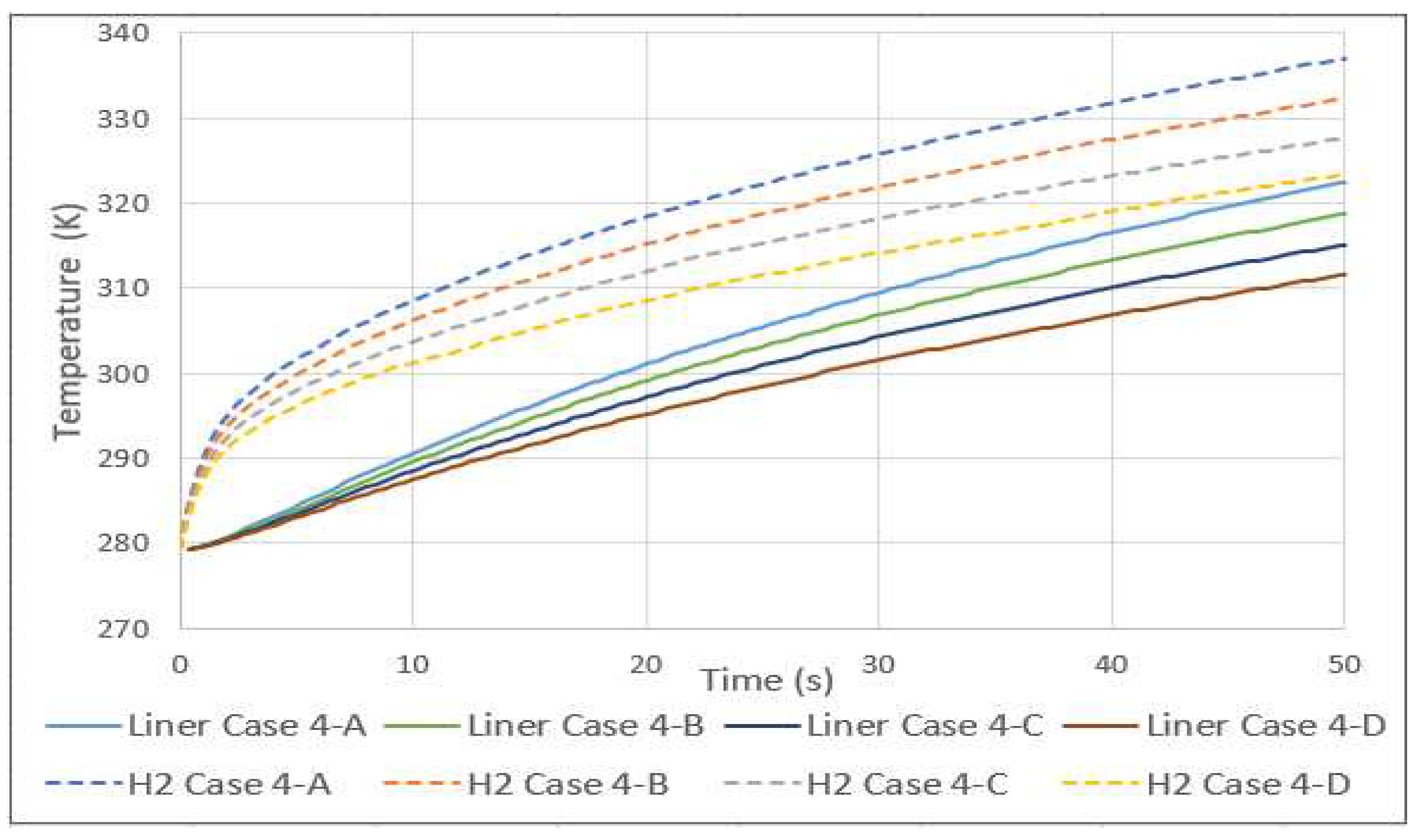
Figure 7.
Variation of velocity with mass flow rate.
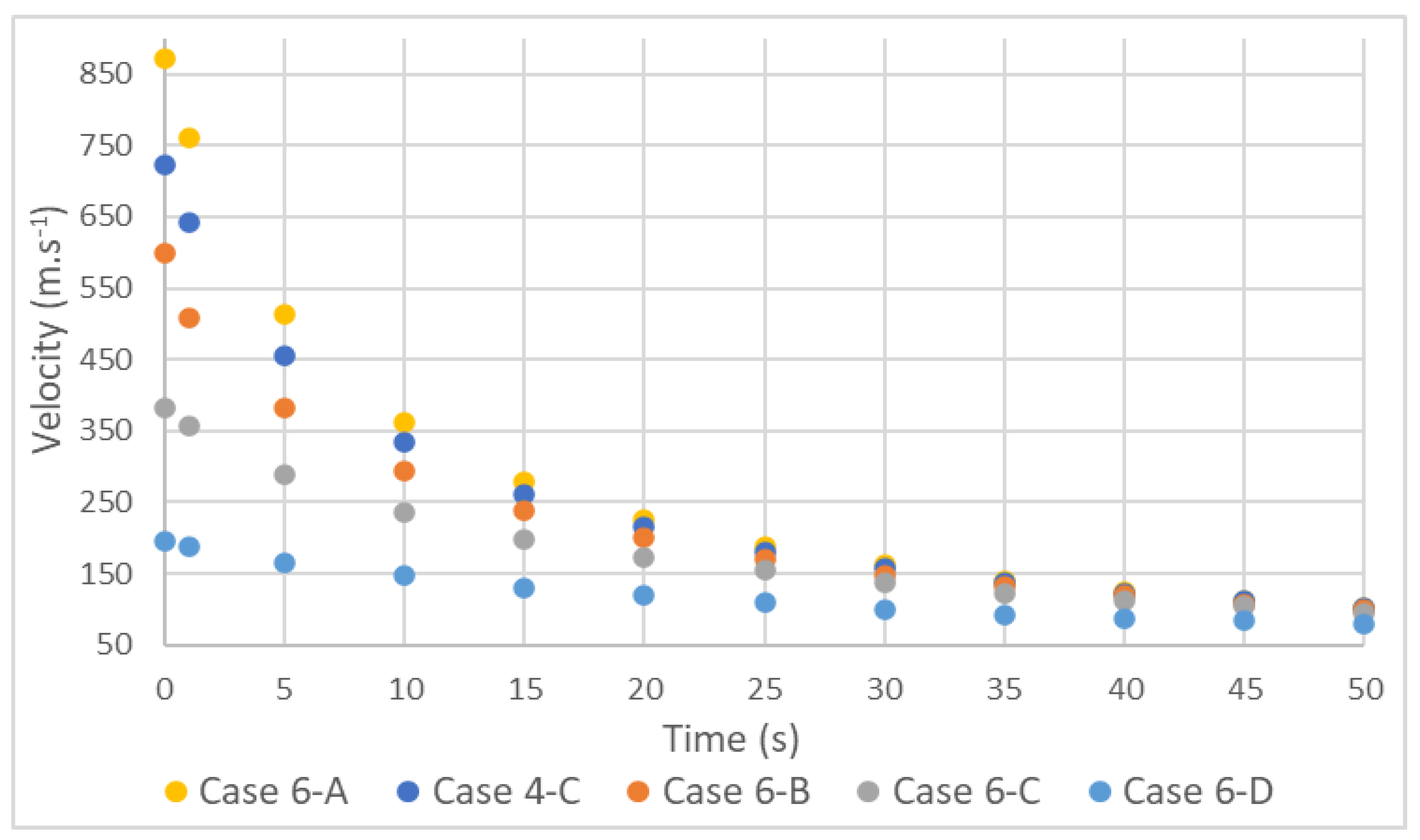
Figure 8.
Variation of Inlet temperature and Mach number with different mass flow rates.
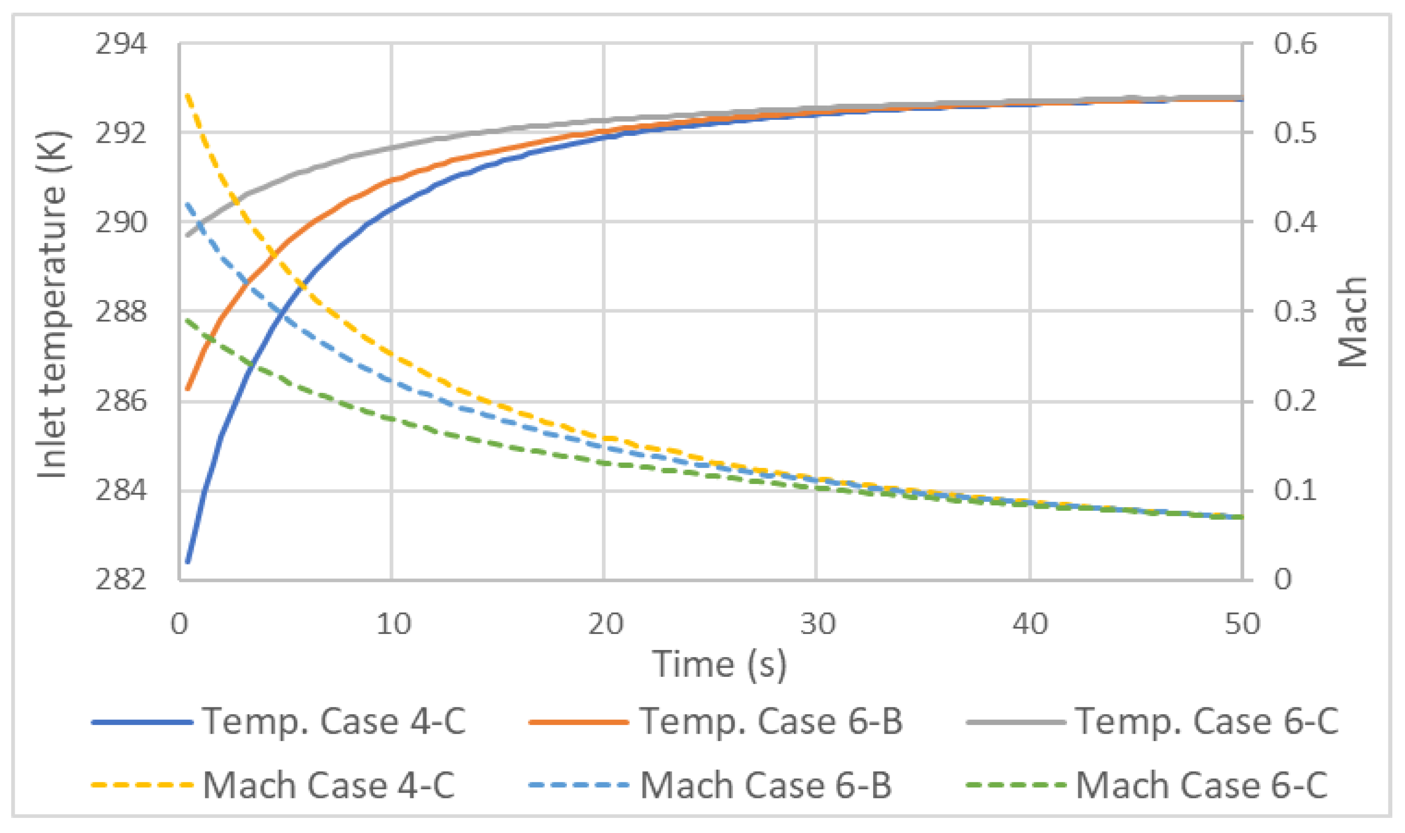
Figure 9.
Adiabatic tank.
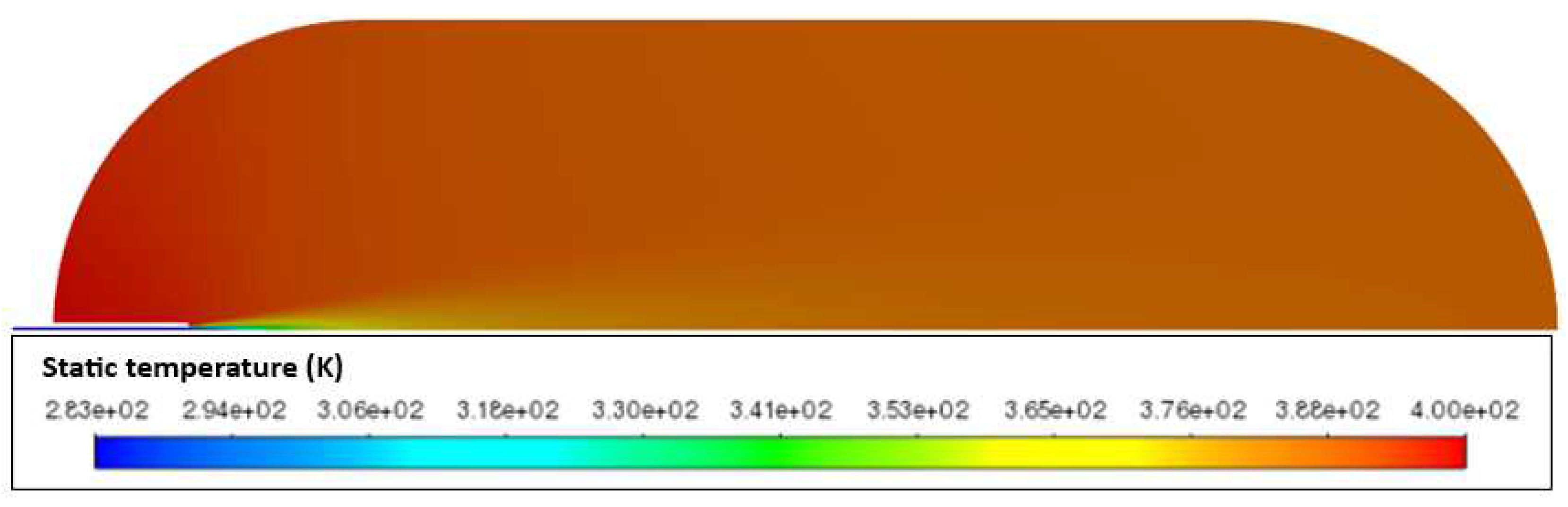
Figure 10.
Temperature increase in a tank type 3 (Case 4) and 4 (Case 8).
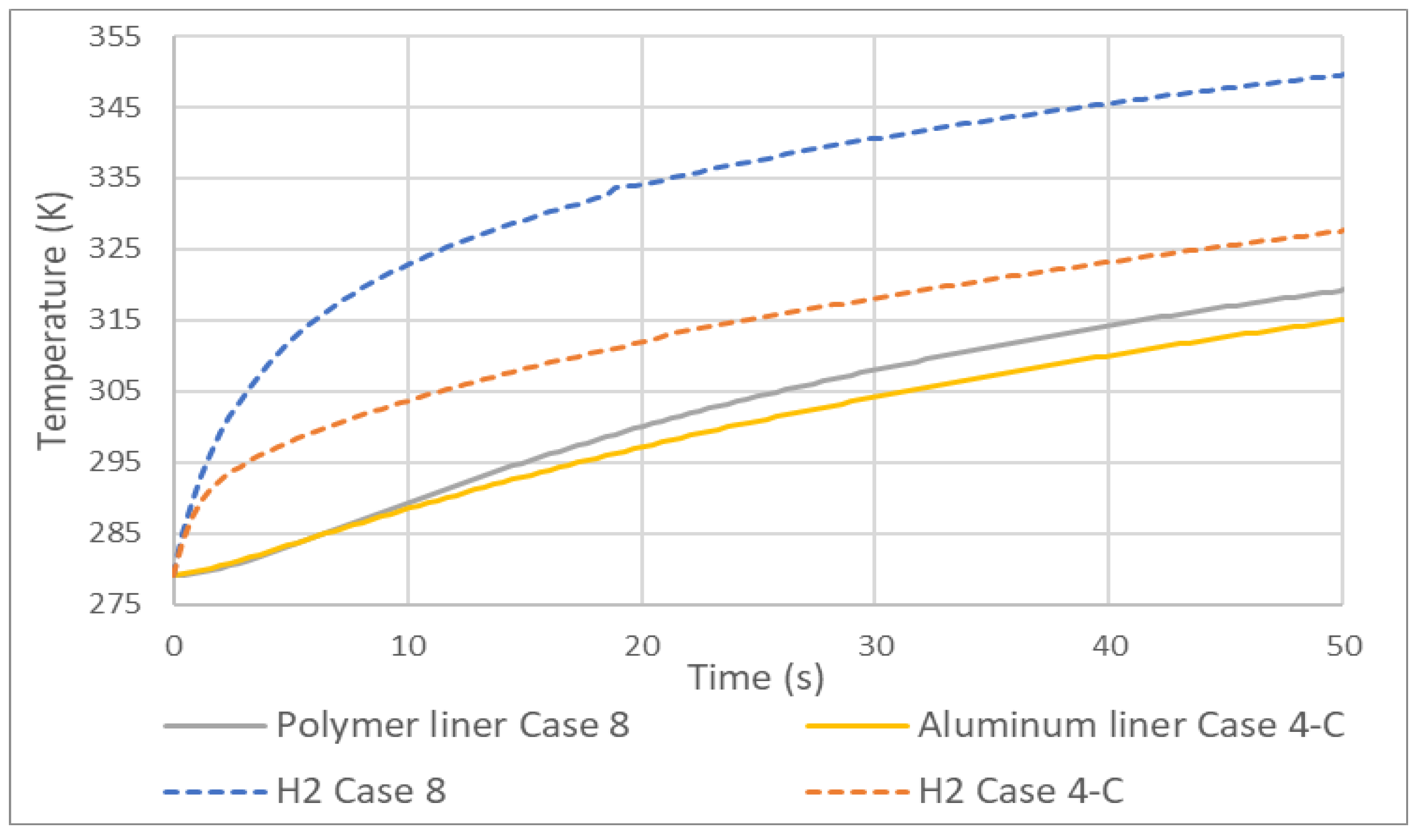
Figure 11.
Comparison between pressure and velocity in a tank type 3 (Case 4) and 4 (Case 8).
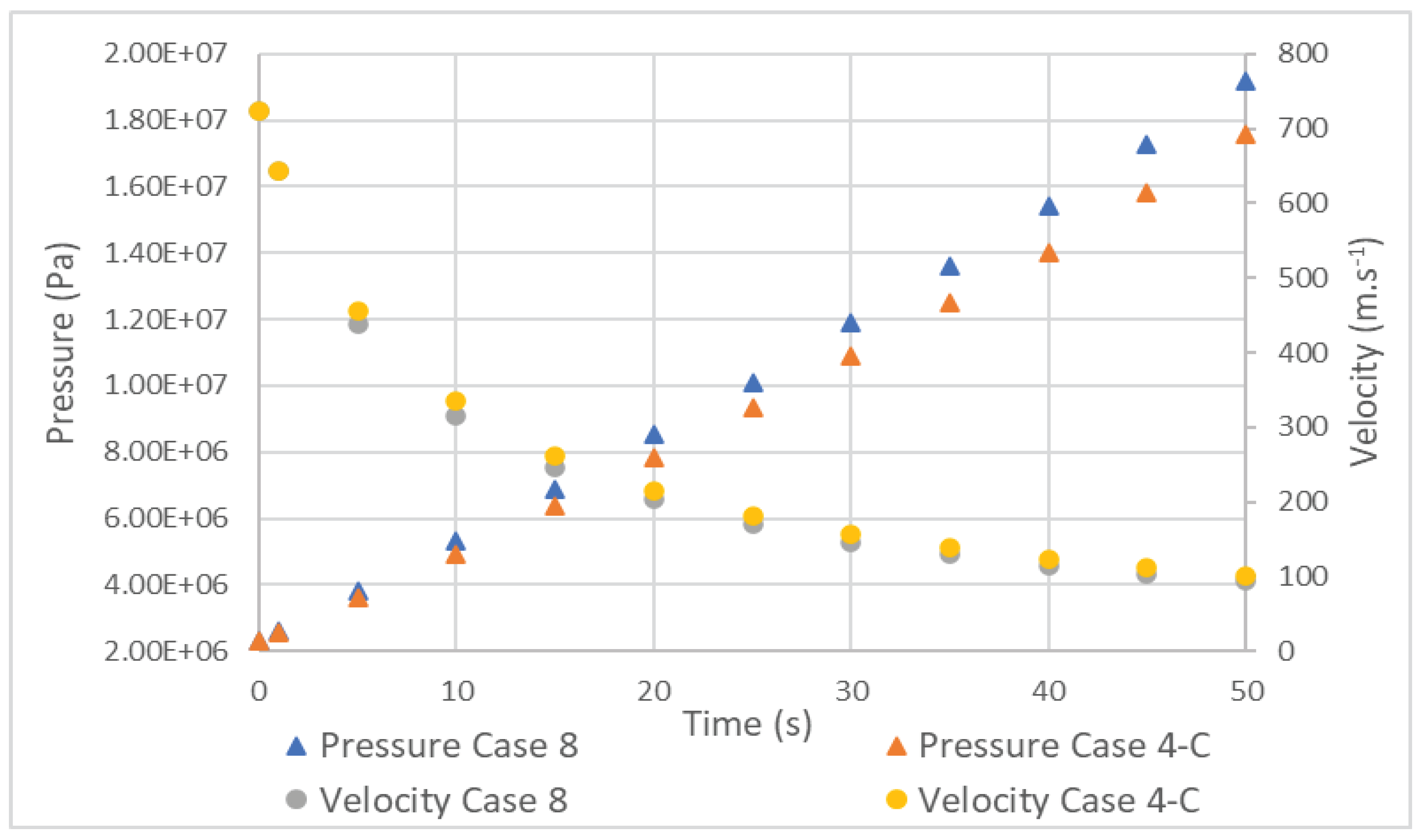

Table 1.
Hydrogen production methods.
| Methods | Inputs | Chemical reactions | Outputs |
|---|---|---|---|
| Steam methane reforming | Methane - CH4 Water - H2O Heat (CH4 burning) |
Steam reforming reaction CH4 + H2O → CO + 3H2 Water-Gas Shift reaction CO + H2O → CO2 + H2 |
Carbon dioxide - CO2 Hydrogen - H2 |
| Pyrolysis | Methane - CH4 Heat (CH4 burning) |
CH4 → C(s) + 2H2 |
Solid carbon – C(s) Hydrogen - H2 |
| Electrolysis1 | Water - H2O Electricity |
Anode 2H2O → O2 + 4H+ +4e- Cathode 2H+ + 2e- → H2 |
Oxygen - O2 Hydrogen - H2 |
1Chemical reactions for PEM eletrolyzer.
Table 2.
Color classification of hydrogen [20] adapted.
Table 2.
Color classification of hydrogen [20] adapted.
| Color | Production method | Production method efficiency |
|---|---|---|
| Grey | Steam reforming and gasification of fossil fuels | 60-85% (steam methane reforming) 74-85% (coal gasification) [3] |
| Blue | Steam reforming or gasification of fossil fuels, with carbon capture and storage | Decreases by 5-14% on the steam methane reforming process [21] |
| Turquoise | Pyrolysis of fossil fuels | - |
| Green | Electrolysis of water using electricity generated from renewable energy sources | 63-70% (alkaline electrolysis) 56-60% (PEM electrolysis) 74-81% (solid oxide electrolyzer cell) [22] |
| Purple | Electrolysis of water using electricity generated from nuclear power plants | |
| Yellow | Electrolysis of water using grid electricity |
| Type | Materials | Cost | Features |
|---|---|---|---|
| Type 1 | All metal | Low | Heavy, internal corrosion. |
| Type 2 | Metal liner with hoop wrapping | Medium | Heavy, internal corrosion. |
| Type 3 | Metal liner with full composite wrapping | High | Lightness, low permeation, galvanic corrosion between liner and fiber, high burst pressure. |
| Type 4 | Polymer liner with full composite wrapping | High | Lightness, high permeation, relatively low burst pressure, no creep fatigue, simple manufacturability. |
Table 4.
Parameters of CFD simulations.
| Simulations | Inlet temperature (K) |
Inicial temperature (K) |
Mass flow rate (kg.s-1) | Exterior temperature (K) |
|---|---|---|---|---|
| Case 1 | UDF | 293 | 0.008 | 293 |
| Case 2 | UDF | 293 | 0.008 | 293 |
| Case 3-A | 313 | 313 | 0.008 | 313 |
| Case 3-B | 303 | 303 | 0.008 | 303 |
| Case 3-C | 293 | 293 | 0.008 | 293 |
| Case 3-D | 283 | 283 | 0.008 | 283 |
| Case 4-A | 313 | 279.2 | 0.008 | 313 |
| Case 4-B | 303 | 279.2 | 0.008 | 303 |
| Case 4-C | 293 | 279.2 | 0.008 | 293 |
| Case 4-D | 283 | 279.2 | 0.008 | 283 |
| Case 5-A | 303 | 303 | 0.008 | - |
| Case 5-B | 293 | 293 | 0.008 | - |
| Case 5-C | 283 | 283 | 0.008 | - |
| Case 6-A | 293 | 279.2 | 0.01 | 293 |
| Case 6-B | 293 | 279.2 | 0.006 | 293 |
| Case 6-C | 293 | 279.2 | 0.004 | 293 |
| Case 6-D | 293 | 279.2 | 0.002 | 293 |
| Case 7-A | 293 | 279.2 | 0.008 | - |
| Case 7-B | 293 | 279.2 | 0.006 | - |
| Case 7-C | 293 | 279.2 | 0.004 | - |
| Case 8 | 293 | 279.2 | 0.008 | 293 |
Table 5.
Dimensions of the tank.
| Internal length (m) | Inner radius (m) | Liner thickness (m) | Laminate thickness (m) |
|---|---|---|---|
| 0.702 | 0.145 | 0.004 | 0.015 |
Table 6.
Summary of Solver parameters.
| Parameter | Value |
|---|---|
| Solver | Pressure-Based (Segregated) [13], [37] |
| Pressure-Velocity coupling | SIMPLE [8], [10] |
| Spatial discritization | Second Order / Second Order UPWIND [37] |
| Temporal discritization | Second Order Implicit [38] |
| Gradient discritization | Least-Squares Cell-Based |
Table 7.
Difference of temperatures between models.
| Hydrogen final temperature (K) | Aluminum liner final temperature (K) | |
|---|---|---|
| Realizable Case 2 | 320.177 | 313.118 |
| Standard Case 1 | 319.104 | 312.633 |
Table 8.
Máximum values of pressure and velocities for Case 3.
| Final pressure (MPa) |
Initial velocity (m.s-1) |
Final velocity (m.s-1) |
|
|---|---|---|---|
| Case 3-A | 19 | 769 | 100.5 |
| Case 3-B | 18.5 | 746 | 100 |
| Case 3-C | 18 | 723 | 99.5 |
| Case 3-D | 17.5 | 700 | 99 |
Table 9.
Temperature difference between Case 5 and 3.
| 5-A and 3-B | 5-B and 3-C | 5-C and 3-D | |
|---|---|---|---|
| Temperatures (K) | 56.11 | 54.03 | 52.09 |
Table 10.
Difference in temperatures between Case 7 and 4.
| 7-A and 4-C | 7-B and 6-B | 7-C and 6-C | |
|---|---|---|---|
| Temperatures (K) | 60.83 | 61.38 | 60.07 |
Disclaimer/Publisher’s Note: The statements, opinions and data contained in all publications are solely those of the individual author(s) and contributor(s) and not of MDPI and/or the editor(s). MDPI and/or the editor(s) disclaim responsibility for any injury to people or property resulting from any ideas, methods, instructions or products referred to in the content. |
© 2023 by the authors. Licensee MDPI, Basel, Switzerland. This article is an open access article distributed under the terms and conditions of the Creative Commons Attribution (CC BY) license (http://creativecommons.org/licenses/by/4.0/).
Copyright: This open access article is published under a Creative Commons CC BY 4.0 license, which permit the free download, distribution, and reuse, provided that the author and preprint are cited in any reuse.


