Submitted:
13 December 2023
Posted:
15 December 2023
You are already at the latest version
Abstract
New or in-service truss bridges, with or without upper bracing systems, may display instability phenomena such as general lateral torsional buckling of the upper chord. The buckling of structural elements, particularly in the case of steel bridges, can be associated with the risk of collapse or temporary/permanent withdrawal from service. Buckling poses a significant danger as it often occurs at lower load values compared to those considered during the design phase. Additionally, this phenomenon can manifest suddenly, without prior warning, rendering intervention for its prevention impossible or futile. In contemporary times, most research and design calculation software offer the capability to establish preliminary values for buckling loads, even for highly intricate structures. This is typically achieved through linear eigenvalue buckling analyses, often followed by significantly more complex large displacement nonlinear analyses. However, interpreting the results for complex bridge structures can be challenging, and their accuracy is difficult to ascertain. Consequently, the objective of this paper is to introduce an original method for a more straightforward estimation of the buckling load of the upper chord in steel truss bridges. The method utilizes the theory of beams on an elastic foundation. The buckling load of the upper chord was determined using both the finite element method and the proposed methodology, yielding highly consistent results.
Keywords:
truss bridges
; buckling
; eigenvalue buckling
; large displacements
; buckling load
; finite element method
; conservative loads
1. Introduction
In the past decade, rapid evolution and advancements in structural analysis software, alongside increased computing speed and storage capacity, have provided bridge designers with the capability to analyze increasingly intricate solutions. Furthermore, another focal area of research has been enhancing the physic-mechanical characteristics of construction materials in terms of strength and durability. These developments have led to new bridge designs with larger dimensions, being more slender and lighter compared to traditional beam bridges. As a result, the advantages from an economic standpoint are evident. However, especially in the realm of steel bridges, these advantages come with a higher risk of general or localized instability phenomena.
The truss girders represent a design solution used for road, railway, and pedestrian bridges in the field of medium to large spans. Compared to other alternative solutions, these types of structures feature lower steel consumption, and due to the presence of structural components developed in all three spatial directions, they possess a redundancy that ensures greater safety in operation.
In the case of steel truss bridges supporting the way at the bottom and lacking an upper bracing system, specific external loading conditions can induce out-of-plane buckling in the compressed top chord. This occurs because, in the transverse direction, only the transverse semi-frames formed by cross beams, verticals, and diagonals counteract the tendency for lateral displacement of the chord. Therefore, in the analysis of the stability of the compressed top chord, it is permissible to use a simplified calculation model, namely the model of a beam on a continuous elastic foundation.
The stability of compressed chord of truss bridges, analyzed as bars on an elastic foundation, is extensively discussed in specialized literature. Determining the critical loading value typically relies on employing existing theoretical methods found in literature, involving a multitude of variables such as: the elastic constant of the elastic foundation or discrete elastic supports in the transverse direction, the type of axial force variation along the element, the type of end restraints of the element, the presence of upper bracing systems, the buckling length value, the existence of execution imperfections and alterations in the physical and mechanical characteristics of the material composing the element during the deformation process.
For some of these variables, proposed approaches have been suggested and are considered within existing design standards. However, for others, clear provisions have not been established, as the issue remains under global study.
Thus, in [4] and [18], the results of studies regarding the influence of upper bracing systems on the stability loss mode of compressed chords in truss bridges are presented. Additionally, the issue of the position of bracing systems is addressed, including their composition (solely diagonals, solely cross beams, or combinations thereof), and the number of bracing planes.
In [5], the authors present the effects of considering material nonlinearity and geometric imperfections on the critical buckling load of the compressed chord in truss bridge structures. Additionally, the study investigates this phenomenon while considering elastomeric bearings with lead cores. The issue of initial geometric imperfections resulting from the industrial manufacturing processes of bridge elements is also addressed in [15]. The influence of imperfections present in some of the elements contributing to the stiffness of the transverse frames, specifically cross beams, verticals and diagonals, is studied. Work [19] comprises a theoretical study regarding the stability on the von Mises framework, well-known in specialized literature, but introduces novelty by considering the post-elastic behavior of materials in the study of structural elements' stability.
Halpern and Adriaenssens present in [7] a study regarding the general nonlinear in plane buckling of truss-arches and propose alternative simplified equivalent models of arches for calculations. These models aim to accurately provide the critical buckling load value comparing with the results obtained using the general buckling theory or finite element models.
In a lot of theoretical studies on the general buckling of compressed chords, determining the critical buckling load is often achieved using energy methods, which provide exact values. However, there are alternative approaches, as presented in [10]. The article compares the results of the lateral buckling analysis of the compressed chord for a truss footbridge using methods proposed by Holt (1952), Timoshenko and Gere (1961), Alberta Transportation (2016) and British Standards Institution-BS (2000). The authors conclude that the Holt and BS methods are the most conservative, while the other two yield similar results.
The factors that have the greatest influence on the critical buckling load of compressed chords in truss bridge structures include the buckling length, the distribution of axial force along the chord and the presence and type of transverse loading. Studies presented in [6] and [8] address the values of buckling lengths recommended for practical stability analyses of compressed chords in truss bridges. These values are discussed in comparison with those stipulated in current standards. Additionally, authors in [9], [11], and [14] propose alternative methods for considering the distribution of axial force along the compressed chord, comparing them to the commonly used parabolic distribution. In [11], the critical loading value was obtained by considering the element continuously supported on an elastic Winkler or Pasternak foundation, taking into account only axial forces, only transverse forces and combinations of axial and transverse forces. Furthermore, the influence of different types of end restraints on the element was investigated.
Starting from the classic model proposed by Engesser for the analysis of a beam on an elastic foundation, over time, alternative models for studying the stability of compressed chords in truss bridges have been proposed. These models, as those presented in [12] and [20], involve discrete elastic support elements, allowing for the determination of the critical buckling load with sufficient accuracy. These studies explore various configurations of the arrangement of elastic supports, as the distance between them and their corresponding stiffness.
As observed, the issue of general stability in compressed chords of truss bridges has been extensively studied over time. However, general instability phenomena not only occur in truss bridges but also in other types of bridges, such as those with arches, especially when the supporting structure comprises a single centrally positioned arch [13], [16], [17]. Despite the increasing availability of calculation programs that enable both linear eigenvalue buckling and nonlinear analyses, solving the problem of general stability in these bridge types remains incomplete. Determining the critical buckling load for general instability is challenging because, although it can be obtained through automatic calculation, it cannot be directly verified. This is due to the impracticality of conducting natural-scale tests on such structures or their elements.
Taking this aspect into account, this article presents an alternative simplified theoretical method for calculating the critical buckling load of compressed chords. The study builds upon existing theoretical approaches in literature and extends them to encompass various end restraint situations for the element, considering both conservative and non-conservative axial compressive forces. The critical loading value obtained using the proposed methodology is compared with values obtained through classical theoretical methods and also more elaborate finite element models.
2. The formulation of the stability problem. The deduction of critical loading from the literature
In the case of a beam supported by multiple equally spaced elastic supports [3], all having the same stiffness and subjected to an external compressive force P, the effect of these supports on the buckled beam can be replaced by the action of a continuous elastic foundation (Figure 1).
The elastic response of the foundation in a current section of the beam will be proportional to the displacement in that section. Denoting α as the elastic constant of each support and 'a' as the horizontal distance between two support points, the stiffness of the elastic foundation can be expressed by the coefficient β:
where β represents the elastic modulus of the foundation.
In other words, the value of β above represents the magnitude of the foundation soil reaction per unit length when the displacement equals unity. Considering the coordinate system in Figure 1, the deformed axis of the bar can be represented by the series:
The bending strain energy of the bar can be expressed as:
Expressing the strain energy of the elastic foundation and considering that the reaction of an element dx of the beam is βydx, it can be written as:
The mechanical work done by the compressive forces P is expressed as:
Expressing the equality between the mechanical work done and the system's energy, it can be written as:
so that the force P will be:
Minimizing the expression (7) implies finding a relationship between the coefficients a1, a2, ... an and leads to the critical value of the force P. Considering all coefficients to be equal to 0 except for one, the deformed axis will take on a sinusoidal shape. Considering that this coefficient different from 0 is am, it can be written as:
and the critical load will be given by the relationship below:
In the above relationship, m represents the number of sinusoidal half-waves into which the buckled beam can be divided, β provides information regarding the elastic support of the beam, while l, E, I are intrinsic characteristics of the beam.
To determine the number of half-waves for which the aforementioned expression of critical loading attains its minimum, we initially consider the scenario where no elastic medium is present, hence setting m = 1. This scenario characterizes the buckling of a hinged beam. When 0 < β << 1, and m = 1 is considered in equation (9), it is noticeable that under highly flexible elastic conditions, the beam can buckle without exhibiting intermediary points of inflection. Should β > 1, it results in a scenario where the force in equation (9) is lower for m = 2 than for m = 1, causing the beam to buckle with two equal half-waves. The threshold value of β is derived from the condition that at this critical value, the force P derived from equation (9) should yield equivalent values for both m = 1 and m = 2.
So it can be written:
By writing the same equation when the number of half-waves changes from m to m + 1, we will obtain the limit value of β for this case.
The relationship (9) that gives the value of the critical load Pcr can also be written in the form:
where L is defined as the reduced length. Values for the reduced length can be obtained based on tables where ratios of L/l have been established depending on values βl4/16EI.
3. Study on the second order statics of a compressed beam on a continuous elastic foundation
In the case of open truss bridges, in the transverse direction, the lateral displacement tendency of the compressed upper chord is counteracted solely by the transverse half-frames formed by cross-beams, verticals and diagonals. Hence, for the analysis of the compressed chord, the simplified calculation model of a bar placed on an elastic foundation can be assumed.
Let there be an elastic medium characterized by the relationship:
representing the response of the medium to a unit displacement of a beam and having the dimension [FL-2], while p [FL-1]. On the other hand, it is known that in a deformed state, the relationships exist, with q(x) being the effective load on the beam (Figure 2):
It is known that there exists a relationship between the bending moment and displacement:
By taking two more derivatives and assuming EI=const., we obtain:
It is to be noted:
By replacing (19) in (18) results in:
A principle verification of the relationship (20) is the following:
- -
- If the response of the foundation doesn’t exists, that is, = 0⇒ 4 = 0 and leads to the equation:equation corresponding to the second-order statics of the compressed beam.
- -
- If P = 0 ⇒ k = 0 and it results in:relationship corresponding to the beam on elastic foundation.
To solve equation (20), it must be taken into account that it is a second-order differential equation. For the homogeneous equation, the characteristic equation takes the form:
Relation (24) can also be written as:
The solution of the differential equation will differ depending on whether the discriminant Δ is positive or negative.
3.1. Case 1
The discussion begins with the case where the discriminant is positive [1], [2] (i.e., for small values of λ and large values of k).
Thus,
The final solutions are:
The solution of homogeneous equation is:
But,
And incorporating i into the constants, it can be written as:
The general solution is:
for equation (20) depends on the form of the function q(x), that is, on the load.
The integration constants are determined from the boundary conditions.
A verification of relationship (31) is the following:
If λ = 0, from relationship (26) and (28) it results: d = 1 and α = k, while β = 0, thus r3 = r4 = 0 and the general form becomes:
namely, the homogeneous part of the equation of the deformed axis of the compressed beam in second-order statics.
3.2. Case 2
The discriminant, is in this case, negative.
Thus,
where d1 here is positive, meaning
For the homogeneous equation, the solutions are:
Let's attempt a transformation of relationships (36) for the root r1:
where retaining the positive part from the parenthesis results in:
For the second root r2, we can write:
and retaining the positive part from the parenthesis results in:
For the third root r3, we will have:
and proceeding in the same manner as with roots r1 and r2, we obtain:
and after retaining the positive part results:
For the fourth root r4, the calculation relationships are:
And applying the same calculation procedure yields:
and after retaining the positive part finally results:
So for all the roots of the homogeneous equation (23), r1, r2, r3, r4, we obtained the same form. Further notations are introduced:
Therefore, the solution of the homogeneous equation will be of the form:
An immediate verification of solution (56) is the following: when k = 0 (thus, there is no force P), it results in and solution (56) exactly takes the form of the solution corresponding to beams on an elastic foundation.
In studying the stability problem, one starts from the solution (56) of the homogeneous equation because it is observed that for common cases in practice, relationship (34) is fulfilled.
The characteristics of the beam and the elastic foundation are defined, as previously shown, by the quantities . Three possible cases are distinguished (Figure 3):
- a)
- The case of the beam with end supports resting on an elastic foundation
- b)
- The case of the beam without end supports and resting on an elastic foundation - the case of non-conservative forces
- c)
- The case of the beam without end supports and resting on an elastic foundation - the case of conservative forces
Case a) - The boundary conditions that can be written are:
where v represents the vertical displacement of the beam and M represents the bending moment.
Taking into account the previously expressed variables and the expressions (16), (17), and (56), the resulting system of homogeneous equations is as follows:
By solving the aforementioned system of equations (58), i.e., by equating the determinant to zero, we ultimately arrive at a transcendental equation in k (that means, in P). This equation can be solved, for instance, through a stepwise graphical representation of the function Δ (the determinant of the system of equations) for various values of k (or P). The first zero value for Δ will consequently lead to the sought solution.
Similarly, the other two cases corresponding to the beam without end supports and resting on an elastic foundation (non-conservative forces - case b) and conservative forces - case c)) are solved in the same manner.
Case b) - The boundary conditions for this case are:
These conditions lead to the following homogeneous system of linear equations:
Case b) - The boundary conditions are:
Similarly to obtaining the system of equations (60), the system of equations corresponding to this case is also derived, and it is presented below.
4. Validation of the proposed methodology. Case study.
Based on the theoretical considerations presented earlier, a case study was conducted to determine the critical buckling load for a beam placed on an elastic foundation, which also has end supports. For illustration, the upper chord of a steel bridge structure with truss girders in use within the railway network of Romania was considered. The overall shape and dimensions are provided in Figure 4. The same figure also depicts the cross-section of the considered compressed upper chord.
The analysis considered that the elastic supports of the upper chord are constituted by the transversal frames made of cross-beams and verticals (Figure 5).
The unit reaction of the support (taking into account the geometric characteristics of the cross-sectional sections of the cross-beams and verticals) is:
The following parameters are involved in the above relationship:
h is the depth of the main girders;
d represents the distance between the axes of the main girders (the theoretical length of the cross-beams);
E is the Young modulus of steel (E = 2.1 × 10⁵ N/mm2);
Im is the moment of inertia of the cross-section of the verticals (about de strong axis);
Ia is the moment of inertia of the cross-section of the cross-beams (about the strong axis);
represents the transverse displacement of the upper chord caused by the application of unit force at the ends of the verticals.
The reaction per unit length of the elastic supports can be established, taking into account the distance between two consecutive elastic supports therefore the distance between frames (equal to 5.5m), based on the relationship:
The moment of inertia of the cross-section of the upper chord was considered as a weighted average of the moments of inertia of the segments composing the upper chord, as follows:
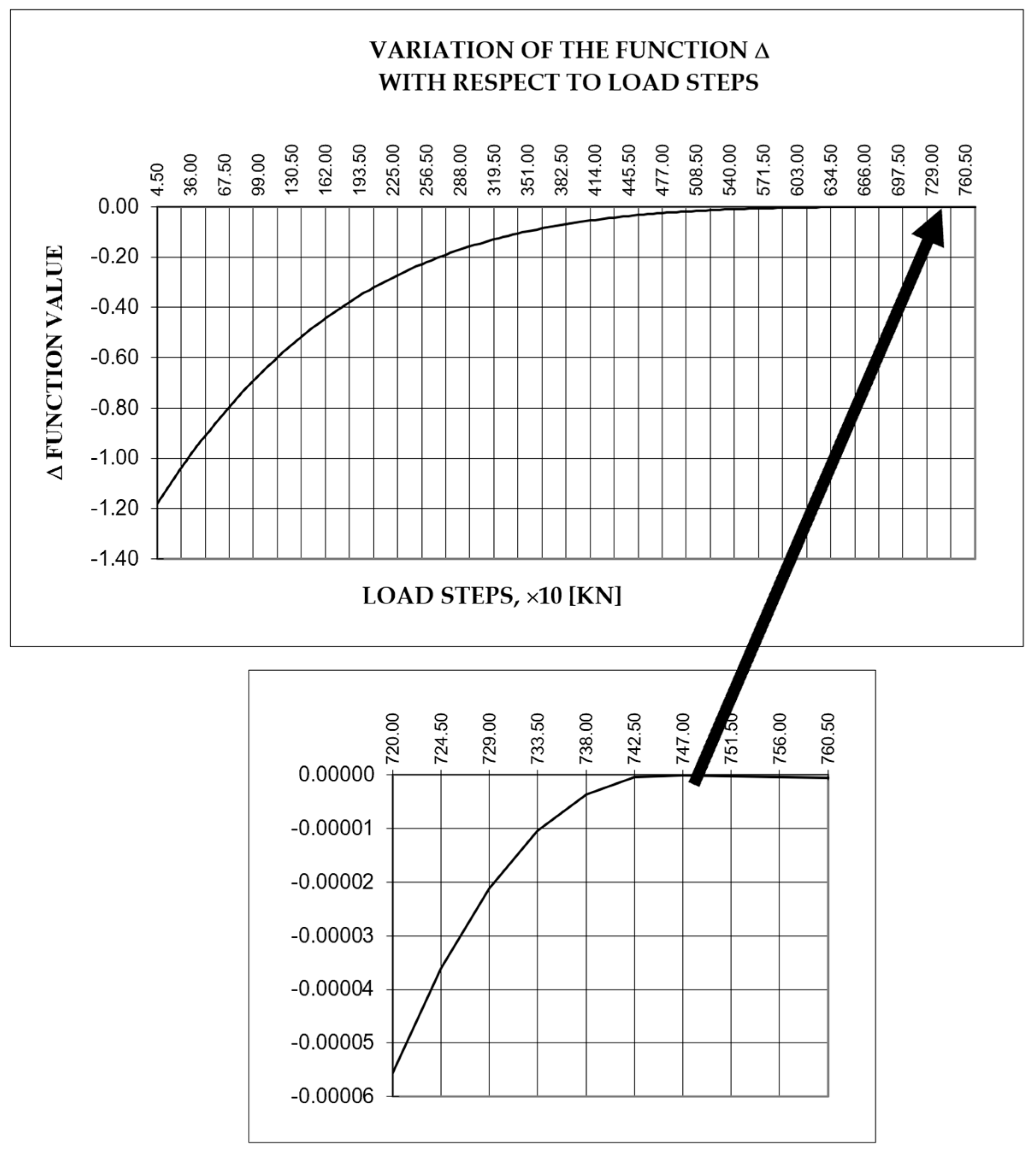
Considering the system of equations (58), taking into account the quantities whose expressions have been previously presented and using a number of load steps, a graphical representation of the determinant function of the system of equations (58) was obtained as a function of the load steps, using a created for this purpose computed program. The abscissa value for which the determinant function equals zero represents the critical load value at which the beam on elastic supports loses its stability. This value is Pcr = 7470 kN. (The P - Δ graph is shown in Figure 6, where Δ represents the value of the determinant of the system of equations (58), here not having the general meaning of displacement as commonly used in second-order analyses).
Starting right now from the equation (13) and considering the characteristics of the upper chord, an equation of the second order in 'm' is obtained, which when solved provides the number of half-waves 'm' of the beam at the moment of stability loss.
The second-order equation is:
and this follows in:
This value of 'm' introduced into equation (9) leads to the following critical load value Pcr:
A value even closer to the one obtained through the calculation using the created program is obtained based on the table values in [3], which provide the value of the ratio L/l based on the ratio . The value of this ratio for the considered case is 72.96 and linearly interpolating in the tables yields the value of the ratio L/l = 0.3784. Hence, the value of the reduced length is (based on the theoretical length of the beam): L = 16.65 m. The critical force Pcr results for this case:
Another analysis was conducted using the finite element method on a three-dimensional spatial model. Following an eigenvalue buckling analysis, the critical buckling force value found was Pcr=7514.5 kN.
5. Discussion
The analysis conducted in this study aimed to determine the general lateral buckling critical load for the compressed upper chord of truss bridge decks using the model of a beam on elastic foundation, The proposed method differs from commonly used methods described in specialized literature. These often focus on the deformation energy of the compressed beam on an elastic foundation, considering various axial force distributions along the bar.
Within the proposed method, the approach starts from the second-order analysis of a compressed beam on a continuous elastic foundation, also considering a possible transverse action on the beam. By analyzing the material characteristics of the beam, cross-section geometric characteristics and the stiffness of the continuous elastic foundation, solutions to the differential equations describing the deformed axis of the compressed beam were obtained. These solutions were adapted for various end-supports of the beam, having as result the formation of systems of linear homogeneous equations. To determine the critical load value, an alternative approach was proposed, plotting the determinant function of each equation system as a function of loading steps, a different approach compared to existing methods.
Using this methodology, a value of Pcr=7470 kN was obtained, closely matching values derived from other methods in the specialized literature. Employing the energy method and pre-determining the number of half-waves of the buckled beam resulted in a critical load value of Pcr,1=8495.2 kN. Another method used for comparison relied on the reduced length of the bar and existing tabulated values, yielding a value of Pcr,2=7509.7 kN.
Considering that the finite element method is currently a standard structural analysis procedure, the critical lateral buckling load for an existing truss bridge deck in Romania's railway network was determined. Following a eigenvalue buckling analysis performed on a discrete three-dimensional model resulted in a critical load value of Pcr,3=7514.4 kN.
As evident from the aforementioned values, the proposed methodology yields a critical buckling load value for the compressed beam on a discrete elastic foundation that aligns closely with values obtained through other existing methods in literature. Moreover, the obtained value is the most conservative, indicating higher safety margins. This consistency in values suggests that the proposed method can effectively be used in stability analyses for compressed upper chords of truss bridge decks.
In this analysis, the transverse rigidity of transversal frames was determined by considering only the influence of cross-beams and verticals. In the future, the method will be expanded to include the contribution of diagonals.
The main advantages of this method lie in the potential for complete automation of the calculation process, a simple analysis model and the use of a reduced set of well-defined parameters describing the calculation model, significantly reducing analysis time. This method could serve as an alternative to current methods like finite element analysis in confirming values obtained for complex structures.
Future studies will further extend this research to account for geometric and material imperfections resulting from construction processes, such as heat treatments of steels, welding procedures or eccentricities of applied compressive forces.
6. Conclusions
The paper presents a detailed analysis of determining the critical lateral buckling load for compressed upper soles of truss bridge decks. The proposed method, involving discrete modeling of the bar on an elastic medium, offers a novel approach compared to traditional methods. It starts from the second-order statics of the compressed bar and employs an innovative strategy to determine the critical load. The detailed analysis of values obtained through various methods confirms the effectiveness and accuracy of the proposed method, suggesting it could be a viable alternative to traditional methods used in structural stability analyses.
Funding
This research received no external funding.
Informed Consent Statement
Informed consent was obtained from all subjects involved in the study.
Data Availability Statement
Data is unavailable due to privacy or ethical restrictions.
Conflicts of Interest
The author declare no conflict of interest.
References
- Iwicki P., Sensitivity analysis of critical forces of trusses with side bracing, Journal of Constructional Steel Research, Volume 66, Issue 7, July 2010, pp. 923-930. [CrossRef]
- Lorkowski P., Gosowski B., Experimental and numerical research of the lateral buckling problem for steel two-chord columns with a single lacing plane, Thin-Walled Structures, Volume 165, August 2021, 107897. [CrossRef]
- Tong M., Mao F., iu H., Structural Stability Analysis for Truss Bridge, Procedia Engineering, Volume 16, 2011, pp. 546-553. [CrossRef]
- Wen Q., Yue Z., Liu Z., Nonlinear stability of the upper chords in half-through truss bridges, Steel and Composite Structures, Vol. 36, No. 3, 2020, pp. 307-319. [CrossRef]
- Silva W.T.M., Ribeiro K.Q., Spatial asymmetric/symmetric buckling of Mises truss with out-of-plane lateral linear spring, International Journal of Non-Linear Mechanics, Volume 137, December 2021, 103810. [CrossRef]
- Halpern A.B., Adriaenssens S., Nonlinear Elastic In-Plane Buckling of Shallow Truss Arches, Journal of Bridge Engineering, April 2014, 20(10):04014117. [CrossRef]
- Dowling D., Walbridge S., A comparative study of methods for analyzing aluminum pony truss structures, Conference “Building Tomorrow’s Society”, Fredericton, Canada, June 13 – June 16, 2018, pp. ST146-1-ST146-10.
- Jankowska-Sandberg J., Kołodziej J., Experimental study of steel truss lateral–torsional buckling, Engineering Structures Volume 46, January 2013, pp. 165-172. [CrossRef]
- Konkong N., Aramraks T., Phuvoravan K., Buckling length analysis for compression chord in cold-formed steel cantilever truss, International Journal of Steel Structures, 2017, volume 17, pp. 775–787. [CrossRef]
- Wen Q., Yue Z., Zhou M., Liang D., Research on out-of-plane critical buckling load of upper chord in half-through truss bridge, Journal of Huazhong University of Science and Technology (Natural Science Edition), Volume 4, Issue 1, January 2018, pp. 104-109.
- Dogruoglu A, Kömürcü S., Stability Analysis of Beams Subjected to Distinct Loading Types on Elastic Foundation, Conference: IV INTERNATIONAL CONFERENCE ON ENGINEERING AND NATURAL SCIENCES (ICENS), May 2018, UKRAINE-KYIV, pp. 203-207.
- Qing-Jie W., Zi-Xiang Y., Elastic buckling property of the upper chords in aluminum half-through truss bridges, Structures, Volume 27, October 2020, pp. 1919-1929. [CrossRef]
- Balaz I.J., Koleková Y., Moroczová L., Stability Analysis of Compression Member on Elastic Supports, Procedia Structural Integrity, Issue 17, January 2019, pp. 734-741. [CrossRef]
- Siekierski W., Analytical Method to Estimate the Lateral Restraint for Unbraced Top Chords of Warren-Truss Bridges with Independent Cross-Beam Decks, International Journal of Structural Stability and Dynamics 22(16)., June 2022. [CrossRef]
- Xia, Z., Wen, W., Yan, A., Yan, D., Zhang, X. (2020). Design of Large-Span Steel-Truss Girder Railway Bridge Stiffened by Flexible Arch Rib. In: Arêde, A., Costa, C. (eds) Proceedings of ARCH 2019. ARCH 2019. Structural Integrity, vol 11. Springer, Cham., pp. 679-689. [CrossRef]
- García-Guerrero J.M., Jorquera-Lucerga J.J., Improving the Structural Behavior of Tied-Arch Bridges by Doubling the Set of Hangers, Appl. Sci. 2020, 10(23), 8711. [CrossRef]
- Qing-jie W., Zi-jian R., Structural analysis of a large aluminum alloy truss double-arch bridge, Structures, Volume 29, February 2021, pp. 924-936. [CrossRef]
- Bazant P.Z., Cedolin L., Stability of structures, Elastic, Inelastic, Fracture, and Damage Theories, Oxford University Press, New York, Oxford, 1991.
- Voinea R.P., Beleş A.A., Strength of Materials, Second volume, Editura Tehnică Publishing House, 1958.
- Voinea R.P., Voiculescu D., Simion E.P., Introduction in solid mechanics with applications in engineering, Editura Academiei Publishing House, 1989.
Figure 1.
Scheme of a beam on elastic supports
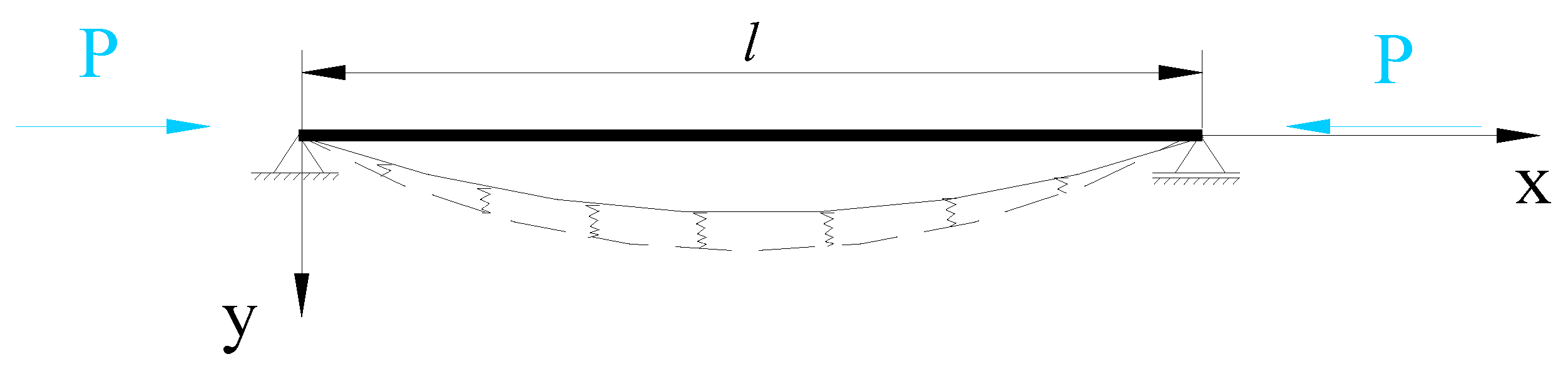
Figure 2.
Scheme of a beam on elastic supports loaded with an axial force P and a transverse uniform distributed load q(x).
Figure 2.
Scheme of a beam on elastic supports loaded with an axial force P and a transverse uniform distributed load q(x).
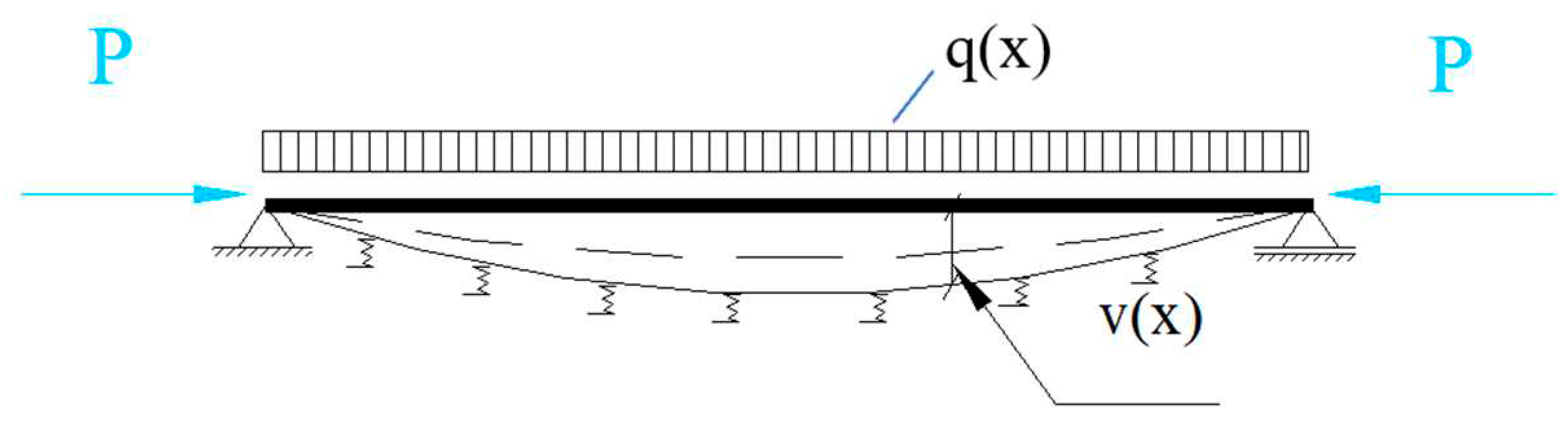
Figure 3.
Model 1, force-displacement curve.
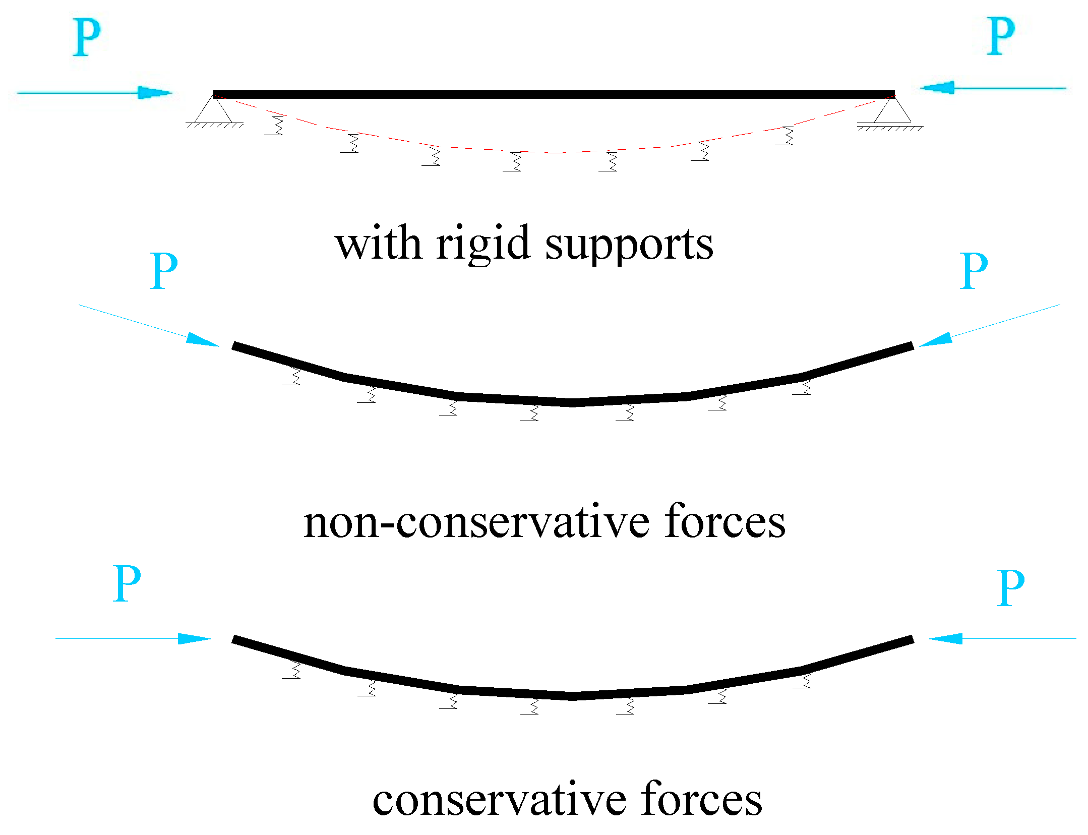
Figure 4.
General layout of the considered truss bridge deck.
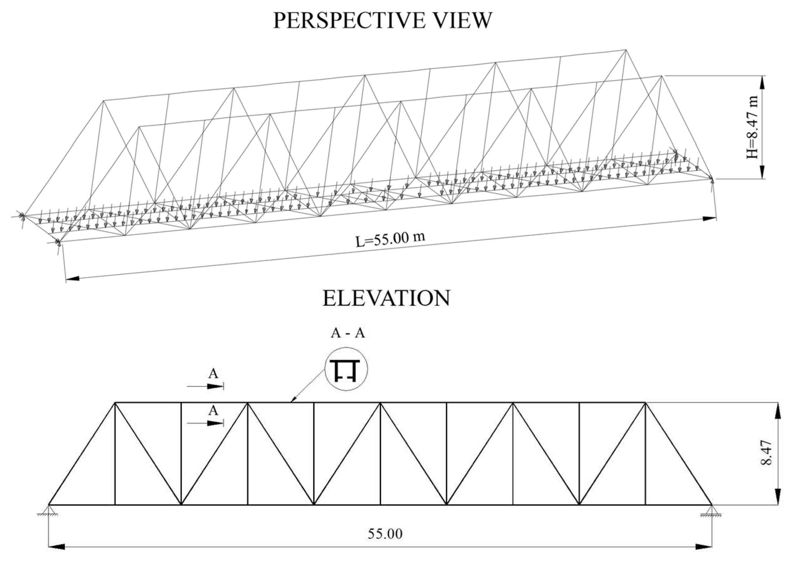
Figure 5.
Scheme for calculation of the elastic supports stiffness.
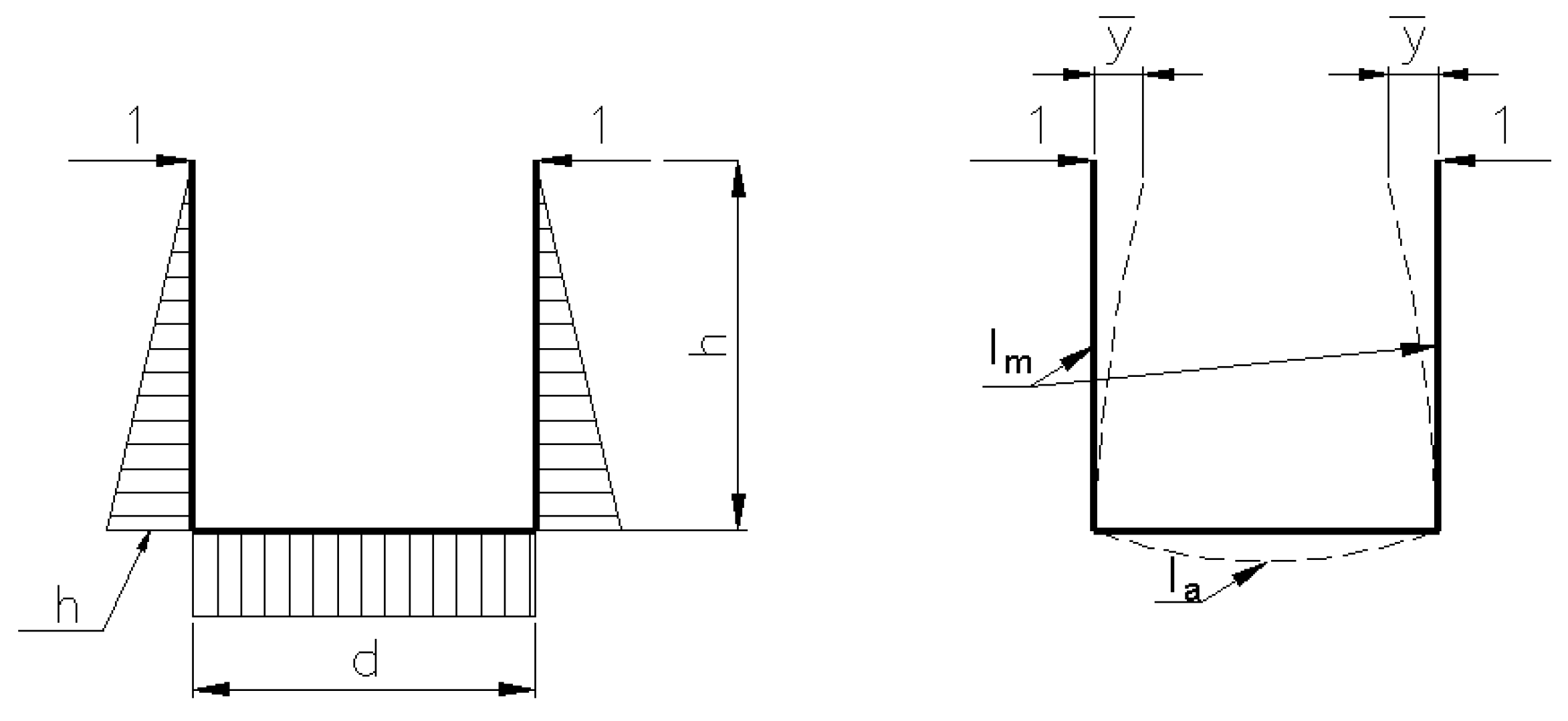
Figure 6.
P-Δ graph obtained using the created computer program.
Disclaimer/Publisher’s Note: The statements, opinions and data contained in all publications are solely those of the individual author(s) and contributor(s) and not of MDPI and/or the editor(s). MDPI and/or the editor(s) disclaim responsibility for any injury to people or property resulting from any ideas, methods, instructions or products referred to in the content. |
© 2023 by the authors. Licensee MDPI, Basel, Switzerland. This article is an open access article distributed under the terms and conditions of the Creative Commons Attribution (CC BY) license (http://creativecommons.org/licenses/by/4.0/).
Copyright: This open access article is published under a Creative Commons CC BY 4.0 license, which permit the free download, distribution, and reuse, provided that the author and preprint are cited in any reuse.


