Submitted:
12 December 2023
Posted:
12 December 2023
Read the latest preprint version here
Abstract
The automotive industry is continuously developing to meet the needs of users in terms of efficiency and convenience. The Thailand government has set a policy for Thailand to be a hub for the production of electric vehicles and key components in the region, with a target to produce electric and zero-emission vehicles by 2030. This article is an example of communication in an electric vehicle system. The CAN Bus system is a communication system in electric vehicles that can receive and send communication data via CAN-Hight/Low lines designed for vehicles. CAN Bus is a standard communication system supported by global organizations and used in modern automotive systems. The design of the communication system in electric vehicles uses MRS Developers Studio software to help write programs to receive and send data and prioritize the importance of the received data. The system consists of communication examples studied, such as pressing the start button, turning on/off the headlights, turning on/off the turn signal, turning on/off the brake light, turning on/off the emergency light, sending the horn signal, sending the signal to shift forward/backward, and tuning the motor gear system. From the communication examples mentioned, the communication will be a prototype transport set for small electric vehicles under the scope of the lithium battery energy storage system, NMC type, size 72 V 25 Ah, to test the use, efficiency, and stability in CAN Bus communication up to 1000 times.
Keywords:
CAN bus system
; MRS developers studio
; electric vehicle
; battery pack
; communication in electric vehicles
0. About the Thesis
This thesis consists of 5 sections: Section 1 introduction and importance: discusses the background and significance of research in the field of electric vehicle communication. Section 2 contents: mentions the creation of a small vehicle communication prototype, a 72 V 25 Ah battery pack, energy use control system, and the CAN Bus communication system in various devices. Section 3 research methodology: starts with writing the MRS Developer Studio program for various communications to simulate on the designed circuit board before installing it in a small vehicle prototype. Section 4 test results: after uploading the program into the CAN Bus control system, the number of tests is conducted to ensure efficient operation and prevent errors. Section 5 conclusion: the research concludes that the communication in the CAN Bus system is effective and suitable for use in the present or future.
1. INTRODUCTION
Many countries have set goals to transition to electric vehicles and have implemented widespread measures to promote their use. By 2030, Norway, Denmark, Iceland, Singapore, and the United Kingdom aim to have 100% of new cars sold to be electric vehicles [1,2]. Japan and China have similar targets for 2035. Each country has developed financial and non-financial support packages. For example, France and Germany provide approximately $7,000 in support per electric vehicle purchase. China has established charging [3] stations nationwide and offers both financial and non-financial benefits to electric vehicle buyers [4].
For Thailand, the use of electric vehicles has not been widespread due to factors such as high prices, unclear government support [5,6], insufficient infrastructure, and limited model options. However, as Thailand is a major car manufacturing country, Thailand is crucial for the country to adapt, both for car manufacturers and parts manufacturers, to maintain its status as a significant global production base.
The creation of a supply chain between electric vehicle manufacturers [7], batteries, and key components: As electric vehicles do not require many components found in ICE vehicles (Internal Combustion Engines), from engines, power transmission systems [8] to exhaust pipes, the manufacturing structure of the automotive industry will have to fundamentally change if electric vehicles become more popular. Although the production of electric vehicles reduces the number of parts, each part becomes more important, such as batteries, electric motors, and power converters [8]. Therefore, the collaboration between vehicle manufacturers and key component manufacturers will help these players maintain their competitive capabilities.
The electric vehicles conversion [9] industry or the process of converting internal combustion engine vehicles into electric vehicles, not only helps people save costs in converting old internal combustion engine vehicles into electric vehicles and pushes the country's goal of reducing pollution emissions according to the plan, but also helps maintain the supply chain in this industry, such as auto parts manufacturers and car repair shops.
There are many electric cars available in Thailand, with a wide range of prices and brands. These include Chinese brands such as BYD, ORA, and NETA, which are affordable and suitable for general city use. There are also premium European brands such as BMW, Mercedes-Benz, MINI Cooper, Audi, and Volvo. These brands offer luxury and premium vehicles at a corresponding price [10]. Although there may not be many electric vehicle charging stations in Thailand, the rising oil prices have led many people to choose electric vehicles. This has resulted in many car brands starting to produce and import electric vehicles into Thailand. This year, Thailand has already started selling EV cars.
Currently, lithium batteries [11] are becoming increasingly popular and are used in almost every device around us, such as mobile phones, power banks, notebooks, various wireless tools, EV cars, drones, electric vehicles, satellites, etc. However, not all lithium batteries used in these devices are of the same type. There are several types of lithium batteries, each with battery advantages and disadvantages.
The Lithium Nickel Manganese Cobalt Oxide battery (NMC) has high specific energy due to the addition of Nickel (Ni) in the cathode composition. This results in a cell with a high voltage of about 3.7 V per cell. Initially, NMC batteries did not include manganese, but researchers added that later to increase stability [12]. The result is an NMC battery that is both stable and suitable for high voltage applications. However, NMC batteries are not suitable for high cranking current applications, such as engine starting.
CAN BUS (Control Area Network) is a protocol designed primarily for the automotive industry. This is popular due to its fast communication and data transmission with various modules, making it widely used in modern vehicle architecture [13,14,15].
In the modern automotive industry, the CAN Bus system is a network of electronic devices that communicate with each other using a common protocol [16,17] called Controller Area Network (CAN). This system is widely used in modern cars. The CAN Bus system allows efficient communication between various electronic devices using only two bus lines, CAN-High and CAN-Low, to transmit data between modules in the car. Each module has a unique identifier and can send and receive messages on the network. In addition, the CAN Bus system provides real-time data transmission and uses a priority-based scheduling format to ensure that important messages are sent first, ensuring that all devices can access the same data at the same time. Data is transmitted using different electrical voltages between the two lines for receiving and transmitting data. At both ends of the line, a 120Ω resistor (called terminating resistor) is connected to reduce resistance for high drive lines and reduce noise signals. The CAN Bus system also helps reduce the complexity of wiring with fewer wires, making it easier to install and maintain the system. The CAN Bus also reduces the weight of the car and increases space for other equipment.
2. ELEMENTS AND COMMUNICATION OF ELECTRIC VEHICLES
This work discusses key topics related to electric vehicle research, including the general structure of electric vehicles, energy management and battery packs, and control systems in electric vehicles through CAN Bus.
2.1. The general structure of the electric vehicle.
This thesis discusses the design of communication systems in small electric vehicles. The materials and equipment used are shown in Table 1, and the software used for simulation and design [18,19,20] is Solid Work. The design is purely mechanical, as shown in Figure 1, which shows the general structure of the electric car.
2.2. 72 V 25 Ah Battery Pack and balance with BMS.
Figure 2. The process of packing [21] a battery to have a voltage of 72 V 25 Ah starts with using a lithium-ion (NMC) battery that has a voltage of 3.7 V 25 Ah. From the calculation, NMC needs 20 cells (follow in equation 1) connected in series to achieve approximately 72 V. Before packing, each cell should be balanced to have the same voltage. Then, pack them in a container to prevent cell dispersion and short circuits. Once the battery pack is ready, connect a BMS to each cell to maintain the voltage level and prevent cell damage.
Battery Pack Shown in equation 1
When n is Number of battery cells
V72V is Battery Packing
V3.7V is Li-Ion (NMC) 1 Cell
2.3. Energy control system in electric vehicles.
Given that the battery pack has a voltage of 72 V, it cannot supply power to the load of devices such as light bulbs, electric accelerators, and power supply boards for controllers, etc. Therefore, a device is needed to reduce the voltage to a suitable level that does not exceed 12 V for operation. Following in Figure 3.
The control unit [22,23,24] of an electric vehicle consists of 4 parts: (1) Vehicle Control Unit (VCU), which controls the operation of the electric vehicle, similar to the ECU in an internal combustion engine vehicle, (2) Motor Control Unit (MCU), which controls the operation of the motor as commanded by the VCU, including the Inverter, (3) DC/DC Converter, which converts direct current voltage for driving the motor, charging the battery, and supplying the 12 V electrical system in the vehicle, (4) Battery Management System (BMS), which monitors and controls battery charging, discharging, temperature checking, charging status, and high-voltage battery energy usage. It also transmits important data to other systems and most importantly adjusts the electrical system of the battery to function as specified.
2.4. CAN Bus Controller.
Figure 4a. The device used for communication is the CAN I/O model PLC 1.033.30B.00 from MRS (MRS Developers Studio). MRS can receive and send data through software programming. The signal is transmitted via a high speed or low speed connection, depending on the usage. This control system needs a 24 V power supply to operate.
This thesis will use 3 CAN Bus Controller devices due to the limitation of inputs and outputs, which have only 6 pins of Analog and 8 pins of Digital shown in Figure 4b. This results in a need for communication to be categorized. Specifically, the CAN Bus Control Box 1 is responsible for receiving signals composed of headlights, front turn signals, horn sounds, and electric throttle to process and send to the CAN Bus Control Box 2. At the same time, the CAN Bus Control Box 2 will receive signals composed of taillights to process and send to the CAN Bus Control Box 3.
From Figure 4a, the signal transmission uses a total of 2 wires from pin P09-CANH, and pin P10-CANL. In other words, if the signal wire is connected from the pin and a 120Ω electrical resistance is paralleled, it will result in high sensitivity data transmission. At the same time, removing the resistance will slow down the data transmission. This article chooses the first method because it requires a response that is sensitive to signals and has the least delay. The signal transmission method is as shown in Figure 5 and the data transmission is limited to hexadecimal.
The operation of the differential wire involves using the difference in electrical voltage between two wires to transmit data, to reduce signal interference. The signal within the wire consists of two states: (1) The Dominant state occurs when the voltage of the CANH wire is greater than the CANL wire, which translates into a logic 0 state. (2) The Recessive state occurs when the voltage of the CANH wire is less than or equal to the CANL wire, translating into a logic 1 state, shown in Figure 6.
The CAN communication standard uses a principle called bit-wise arbitration, which involves a joint assessment of the number of devices (Nodes), wire length, and communication speed (Bit Rate). CAN is an Asynchronous protocol where the data transmission speed is determined by the data rate or baud rate, typically set at 125,000 (125 kbit/s) as the standard.
In addition to the aforementioned equipment, it is necessary to have software for writing communication systems in electric vehicles. The software used is MRS (MRS Developers Studio). The method of writing the communication system will be shown in the next chapter.
3. RESEARCH AND METHODOLOGY
The procedure begins with communication between the device and the software in the CAN Bus test board. The test involves communication of turn signals, brake lights, emergency lights, horn, and motor operation [25]. In addition to communication, wiring and electric vehicle frame formation are also crucial for the results.
3.1. CAN Bus test box.
Figure 7 shows the creation of a board for testing communication with the CAN Bus. This is done before installation in an electric vehicle. The equipment used for testing is listed in Table 2. There are two sets of test boards because if there is a device transmitting data, there must also be a device receiving the data. The communication of data is connected through the CANH-CANL signal line via device number 5, allowing data to be communicated between the two boards.
3.2. MRS Developers Studio.
The communication system of electric vehicles for the CAN I/O control device starts with opening the MRS Developers Studio software and creating a new project, following in Figure 8a. Should input the address according to the CAN I/O box, which is modelled PLC 1.033.30B.00, select Revision as type E, and name the project as desired. If the information does not match with the CAN I/O box, it will prevent the electric vehicle for communicating.
When open a project, set the numbers in the order shown in Figure 8a, starting from number 1. Use it to update when writing logic in the software, number 2 is used to save the work file, numbers 3-4 are used to set up data transmission between the CAN Bus test box, number 5 is used to determine the response speed for data transmission, number 6 is used to write the logic of the electric vehicle operation, number 7 shows the usage of analog and digital pins, and numbers 8-9 are used to open logic in programming.
In the window Graphical programming click on button “EDIT CAN_DB” (Number 3 from Figure 8b) to show the definitions of CAN block and CAN data points, EDIT CAN_DB is shown in Figure 9.
CAN-block is a CAN frame which is defined by a 11 or 29 (extended) identifier, by a name and by a data content from 0 to 8 bytes. CAN-data point is a variable inside a CAN-block, which is defined by a number of bits within the 8 Bytes array. It is possible to have multiple CAN-data points within the same CAN-block as long as it has bits to be attributed.
From Figure 9, that is indicated that variables need to be set for the transmission of data between devices. The method for setting various parameters is shown in Table 3, and the definition of device variables, whether it’s an electric switch or accelerator, can be set as per Table 4.
From Figure 8b. “Graphical programming” by clicking "Edit more DBs" a new window is opened to specify the settings of all I/O of the module. You can set the digital I/O, analog inputs, PWM outputs and the lists for EEPROM index and user variable index shown in Figure 12. (Parameter use in Figure 10.)
When you have set the variables as needed, for this thesis, we will write logic related to controlling the lighting system [26], using the vehicle's horn, and receiving and transmitting data from the electric vehicle's accelerator and brakes. The entire system is shown in Figure 11a–d.
Considering the logic from Figure 11a–d, the logic is found that there are three devices in the CAN Bus communication device. The CAN Bus1 input side serves to receive the light signal and the operation signal of the key and the car gear. The output side consists of displaying the data received from the input. Due to insufficient working pins, CAN Bus2 is used to display the output of the light signal with the CANH-CANL [27] communication line used for the connection. At the same time, it also receives the electric accelerator signal to display the output in CAN Bus3 with the same communication line. The entire operation process is shown in Figure 12.
3.3. The Construction of Mechanical Structures.
After initial software testing, the next step is to shape the mechanical structure of the electric vehicle. This article will assemble the CAN I/O test suite of all three devices onto the electric vehicle and upload various operational logic to complete it [28,29,30]. The simple structure of an electric vehicle is shown in Figure 13.
4. RESULT
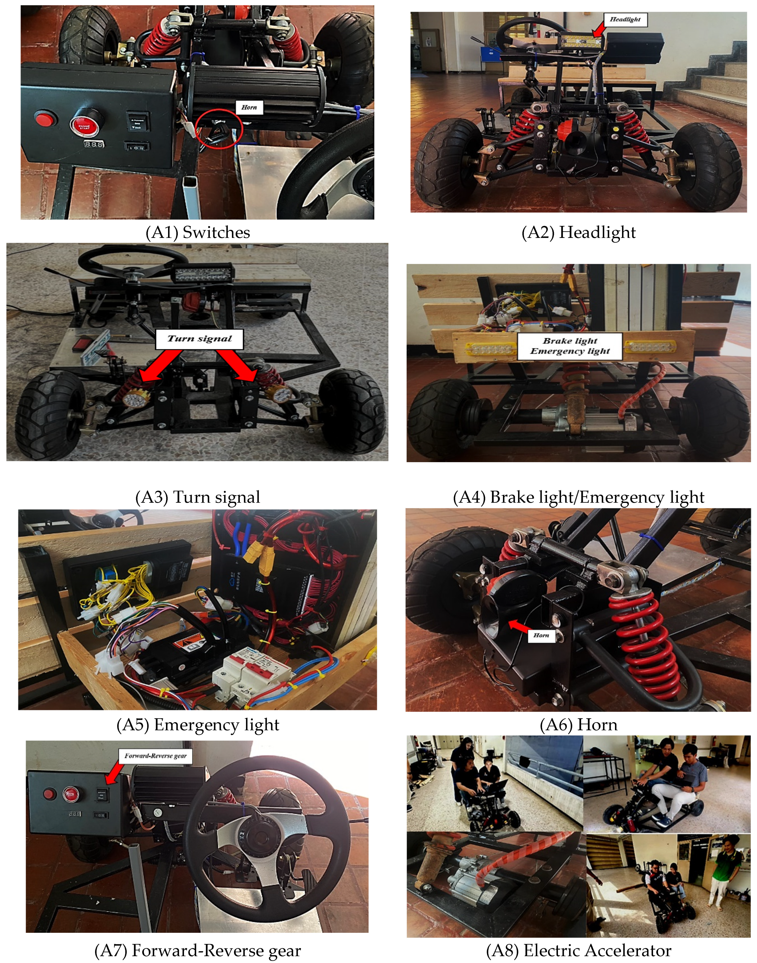
This chapter presents the results from writing logic into the test board as shown in Figure 7. Starting with the car headlights, turn signals, brake lights, emergency lights, forward-reverse gear, switches, horn and electric accelerator in order. Then, the logic is uploaded onto the electric vehicle structure as shown in Figure 14. The test results for the number of uses in electric vehicles are shown in Table 5. The simulation results of the light bulb status on the test board are as shown in Figure 14a–g.
From Figure 14a–g is the upload of software via CAN-HUB line, the results of data communication testing by Figure (a) circuit connection for signal testing in CAN Bus test box; Figure (b) is the display of car front status lights; Figure (c) is the signal transmission of left and right turn lights; Figure (d) is the display of brake status lights; Figure (e) is the transmission of emergency signals by left and right turn lights on together; Figure (f) shows the status of forward and reverse gears and Figure (g) is the tuning of the electric throttle to make the motor work within the specified limits.
3.4. The Cost of electricity per battery charge.
- The electrical energy of the battery can be found from equation (2)
- The unit of electrical energy usage can be found from equation (3)
- Calculating the cost of electricity in Thailand can be found from equation (4)
This From the above equation, calculating the cost for charging a 72 V 25 Ah battery, substituting the given parameters, find that the energy used to charge the battery 100% is 1800 Watt-hour, equivalent to 1.8 units. Therefore, the cost of electricity for charging is 7.182 baht per charge.
From Figure 2, evident that the battery pack, which includes a JIKONG BMS model, allows the user to check the voltage, resistance values of each cell, and the battery pack's charging current through an application. In addition to this, it also enables the user to monitor the temperature status. The different statuses are displayed as shown Figure 15.
5. CONCLUSION
From the study of the electric vehicle communication system simulation project with the CAN Bus system, the simulation set of various I/O devices can receive and send digital signals through the CAN Bus system and can work normally in all systems. Testers can modify the set of program instructions for system operation through modification with the MRS developer studio program. That can upload a set of instructions to overwrite the original set of instructions to modify the operation of the I/O to display as desired. This research is a prototype simulation set in teaching media that is almost like 1 electric car, making it convenient for teaching and learners can understand the operation of the CAN Bus system more from various displays through tangible devices. The simulation set can support 2 seats, acceleration system, light system, and control system will use a 72 V battery that can be charged and use a 1500 W 60V motor as electrical power in driving through working with the Can Bus system.
Acknowledgments
The simulation thesis for the electric vehicle communication system using the CAN Bus system would like to thank Suranaree University of Technology, Faculty of Engineering for their assistance in terms of budget and equipment for the project, as well as advice and close monitoring of the thesis from start to finish.
Appendix A: Testing the communication status in actual use
References
- Y. Yuan, "Research on Electric Vehicle Driverless Test System Based on Computer Big Data Technology," 2023 IEEE 2nd International Conference on Electrical Engineering, Big Data and Algorithms (EEBDA), Changchun, China, 2023, pp. 1018-1022. [CrossRef]
- M. MARINOV, J. PETROV, O. STANCHEV and P. ANDREEV, "Studying the Performance Characteristics of the Electric Vehicle," 2019 16th Conference on Electrical Machines, Drives and Power Systems (ELMA), Varna, Bulgaria, 2019, pp. 1-5. [CrossRef]
- B. Zhu et al., "The Design of Automatic Testing Platform on Electric Vehicle Off-Board Charger Interoperability," 2018 5th International Conference on Information Science and Control Engineering (ICISCE), Zhengzhou, China, 2018, pp. 1276-1279. [CrossRef]
- P. Pedret, G. Bayona, J. Webb, C. Moure and S. Boltshauser, "Control systems for high performance electric cars," 2013 World Electric Vehicle Symposium and Exhibition (EVS27), Barcelona, Spain, 2013, pp. 1-7. [CrossRef]
- Z. Wang and D. Yin, "Design and Implementation of Vehicle Control System for Pure Electric Vehicle Based on AUTOSAR Standard," 2019 22nd International Conference on Electrical Machines and Systems (ICEMS), Harbin, China, 2019, pp. 1-5. [CrossRef]
- J. Valera, L. Huaman, L. Pasapera, E. Prada, L. Soto and L. Agapito, "Design of an autonomous electric single-seat vehicle based on environment recognition algorithms," 2019 IEEE Sciences and Humanities International Research Conference (SHIRCON), Lima, Peru, 2019, pp. 1-4. [CrossRef]
- S. Ledinger, D. Reihs, D. Stahleder and F. Lehfuss, "Test Device for Electric Vehicle Grid Integration," 2018 IEEE International Conference on Environment and Electrical Engineering and 2018 IEEE Industrial and Commercial Power Systems Europe (EEEIC / I&CPS Europe), Palermo, Italy, 2018, pp. 1-5. [CrossRef]
- V. Totev and V. Gueorgiev, "Batteries of Electric Vehicles," 2021 13th Electrical Engineering Faculty Conference (BulEF), Varna, Bulgaria, 2021, pp. 1-6. [CrossRef]
- R. Hou, L. Zhai, T. Sun, Y. Hou and G. Hu, "Steering Stability Control of a Four In-Wheel Motor Drive Electric Vehicle on a Road with Varying Adhesion Coefficient," in IEEE Access, vol. 7, pp. 32617-32627. [CrossRef]
- W. Cao, Z. Zhu, J. Nan, Q. Yang, G. Gu and H. He, "An Improved Motion Control with Cyber-Physical Uncertainty Tolerance for Distributed Drive Electric Vehicle," in IEEE Access, vol. 10, pp. 770-778. [CrossRef]
- E. Siriboonpanit, K. Sasiwimonrit, J. Saelao and N. Patcharaprakiti, "An Air Force Cooling of Lithium–ion Battery Thermal Management System for Heat Eliminating in Modified Electric Vehicle," 2022 International Electrical Engineering Congress (iEECON), Khon Kaen, Thailand, 2022, pp. 1-4. [CrossRef]
- J. Ouyang, D. Xiang and J. Li, "State-of-function evaluation for lithium-ion power battery pack based on fuzzy logic control algorithm," 2020 IEEE 9th Joint International Information Technology and Artificial Intelligence Conference (ITAIC), Chongqing, China, 2020, pp. 822-826. [CrossRef]
- Wang Dafang, Nan Jinrui and Sun Fengchun, "The application of CAN communication in distributed control system of electric city bus," 2008 IEEE Vehicle Power and Propulsion Conference, Harbin, China, 2008, pp. 1-4. [CrossRef]
- Li Ran, Wu Junfeng, Wang Haiying and Li Gechen, "Design method of CAN BUS network communication structure for electric vehicle," International Forum on Strategic Technology 2010, Ulsan, Korea (South), 2010, pp. 326-329. [CrossRef]
- Jinrui Nan, Li Zai, Zhifu Wang and Jun Wang, "Bus Communication and Control Protocol Using the Electric Passenger Car Control System," 2006 6th World Congress on Intelligent Control and Automation, Dalian, 2006, pp. 8288-8291. [CrossRef]
- Z. Wei, B. Li, R. Zhang and X. Cheng, "Contract-Based Charging Protocol for Electric Vehicles With Vehicular Fog Computing: An Integrated Charging and Computing Perspective," in IEEE Internet of Things Journal, vol. 10, no. 9, pp. 7667-7680, 1 May1, 2023. [CrossRef]
- H. Liu, X. Liang, L. Fang, B. Zhang and J. -W. Zhao, "A Secure and Efficient Authentication Protocol Based on Identity Based Aggregate Signature for Electric Vehicle," 2014 International Conference on Wireless Communication and Sensor Network, Wuhan, China, 2014, pp. 353-357. [CrossRef]
- A. Wicaksono and A. S. Prihatmanto, "Optimal control system design for electric vehicle," 2015 4th International Conference on Interactive Digital Media (ICIDM), Bandung, Indonesia, 2015, pp. 1-6. [CrossRef]
- J. Ni, J. Hu and C. Xiang, "Control-Configured-Vehicle Design and Implementation on an X-by-Wire Electric Vehicle," in IEEE Transactions on Vehicular Technology, vol. 67, no. 5, pp. 3755-3766, May 2018. [CrossRef]
- L. Krčmář, J. Břoušek and T. Petr, "Design of Rear Wheel Steering System of an Experimental Electric Vehicle," 2019 International Conference on Electrical Drives & Power Electronics (EDPE), The High Tatras, Slovakia, 2019, pp. 207-210. [CrossRef]
- M. Evzelman, M. M. Ur Rehman, K. Hathaway, R. Zane, D. Costinett and D. Maksimovic, "Active Balancing System for Electric Vehicles with Incorporated Low-Voltage Bus," in IEEE Transactions on Power Electronics, vol. 31, no. 11, pp. 7887-7895. [CrossRef]
- X. Zeng, H. Jing, B. Kuang, F. Chen, W. An and S. Zhao, "Speed Control of Four-Wheel Independently Actuated Vehicle based on MPC Algorithm," 2019 3rd Conference on Vehicle Control and Intelligence (CVCI), Hefei, China, 2019, pp. 1-6. [CrossRef]
- C. Tang, M. Ataei and A. Khajepour, "A Reconfigurable Integrated Control for Narrow Tilting Vehicles," in IEEE Transactions on Vehicular Technology, vol. 68, no. 1, pp. 234-244. [CrossRef]
- H. Xiong, Z. Tan, R. Zhang and S. He, "A New Dual Axle Drive Optimization Control Strategy for Electric Vehicles Using Vehicle-to-Infrastructure Communications," in IEEE Transactions on Industrial Informatics, vol. 16, no. 4, pp. 2574-2582, April 2020. [CrossRef]
- H. Kobayashi, M. Kohriyama, M. Nagata and S. Ohashi, "Study of Deceleration Control using the Power Regenerative Brake to Improve the Ride Comfort in the Electric Vehicle," 2020 23rd International Conference on Electrical Machines and Systems (ICEMS), Hamamatsu, Japan, 2020, pp. 2046-2049. [CrossRef]
- L. Suo and J. Sun, "Design and development of ternary logic sinusoidal pulse width modulated rectifier for electric vehicle charging-discharging device," 2019 IEEE 2nd International Conference on Automation, Electronics and Electrical Engineering (AUTEEE), Shenyang, China, 2019, pp. 418-423. [CrossRef]
- A. -M. Căilean and M. Dimian, "Current Challenges for Visible Light Communications Usage in Vehicle Applications: A Survey," in IEEE Communications Surveys & Tutorials, vol. 19, no. 4, pp. 2681-2703, Fourthquarter 2017. [CrossRef]
- W. Wang, Z. Han, M. Alazab, T. R. Gadekallu, X. Zhou and C. Su, "Ultra Super-Fast Authentication Protocol for Electric Vehicle Charging Using Extended Chaotic Maps," in IEEE Transactions on Industry Applications, vol. 58, no. 5, pp. 5616-5623, Sept.-Oct. 2022. [CrossRef]
- Z. Garofalaki, D. Kosmanos, S. Moschoyiannis, D. Kallergis and C. Douligeris, "Electric Vehicle Charging: A Survey on the Security Issues and Challenges of the Open Charge Point Protocol (OCPP)," in IEEE Communications Surveys & Tutorials, vol. 24, no. 3, pp. 1504-1533, thirdquarter 2022. [CrossRef]
- Song Xuehua, Lu Min, Wu Hesheng, Wang Hong and Liu Fei, "The solution of hybrid electric vehicle information system by modbus protocol," 2011 International Conference on Electric Information and Control Engineering, Wuhan, 2011, pp. 891-894. [CrossRef]
Figure 1.
General structure of the Electric vehicle.
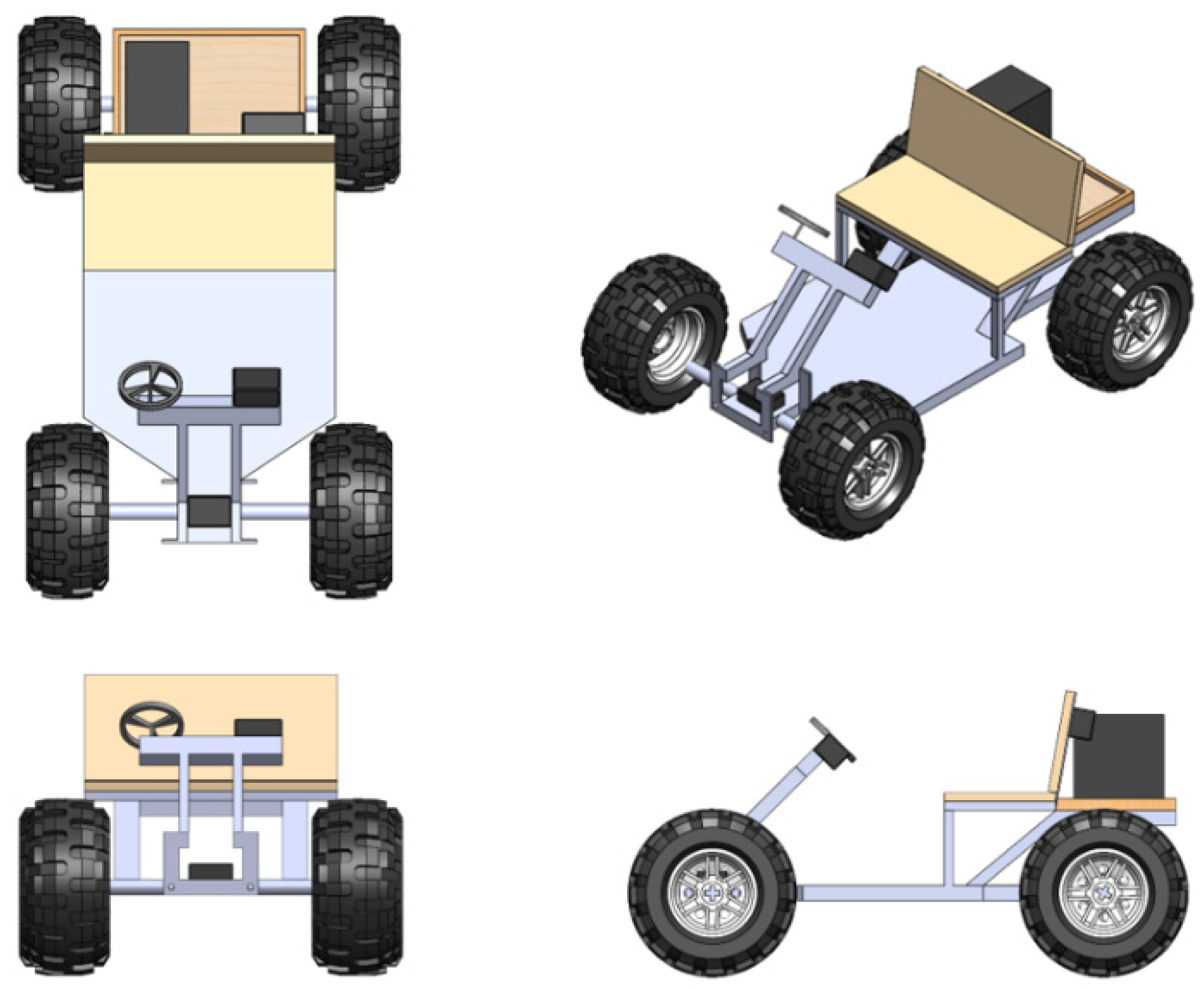
Figure 2.
Battery pack and balance with BMS.
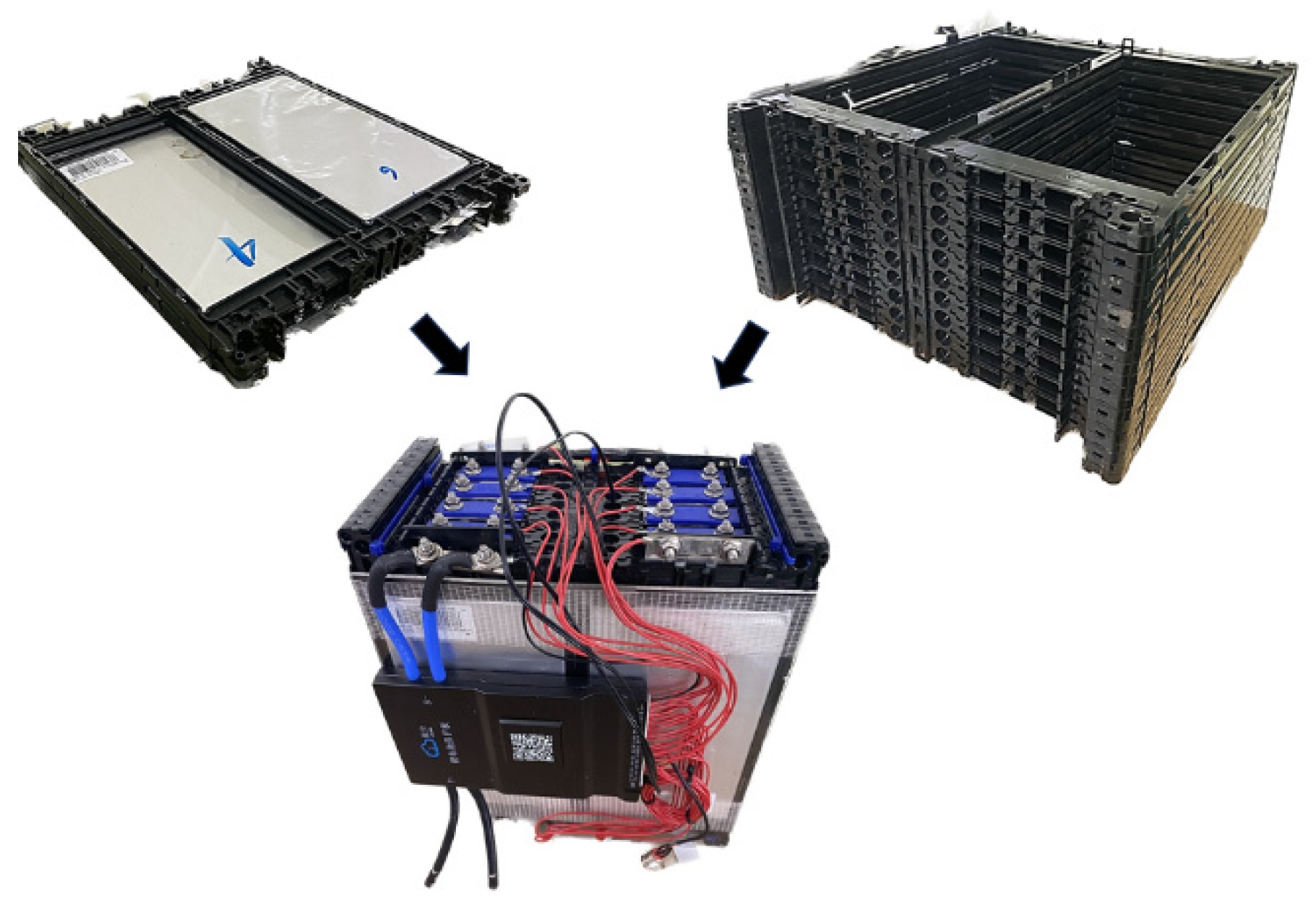
Figure 3.
Energy control system.
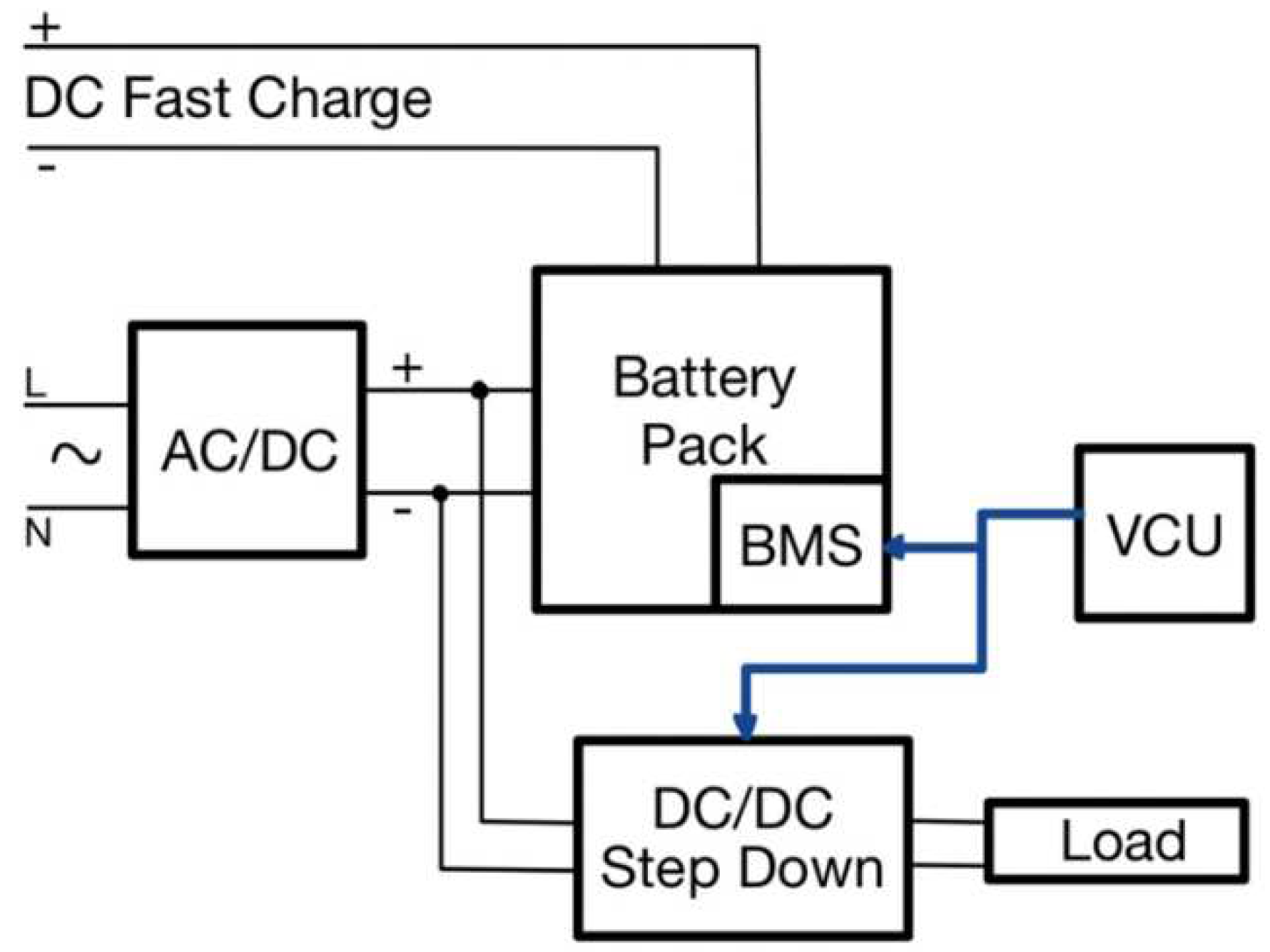
Figure 4.
Controller: (a) CAN Bus Controller; (b) Communication CAN Bus.
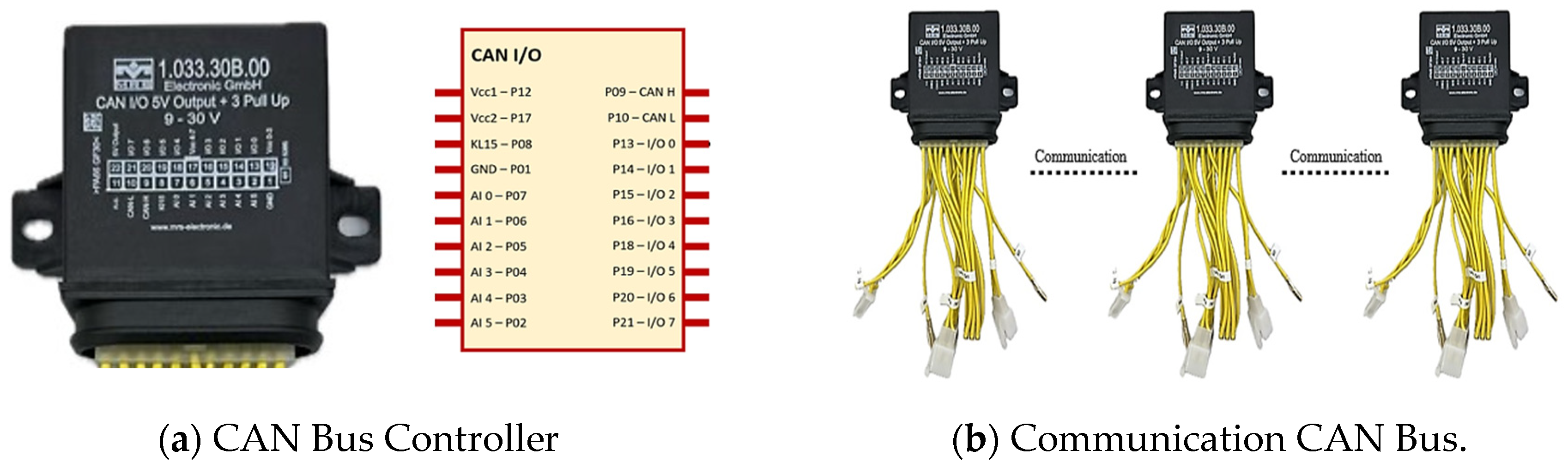
Figure 5.
Signal transmission method.
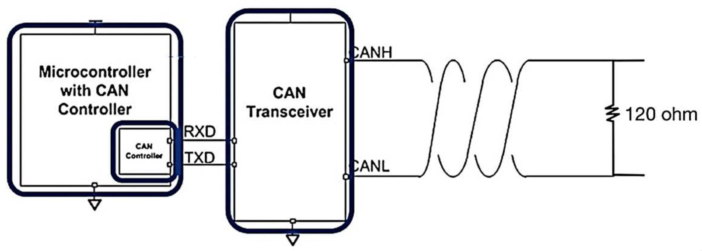
Figure 6.
Status of data transmission line.
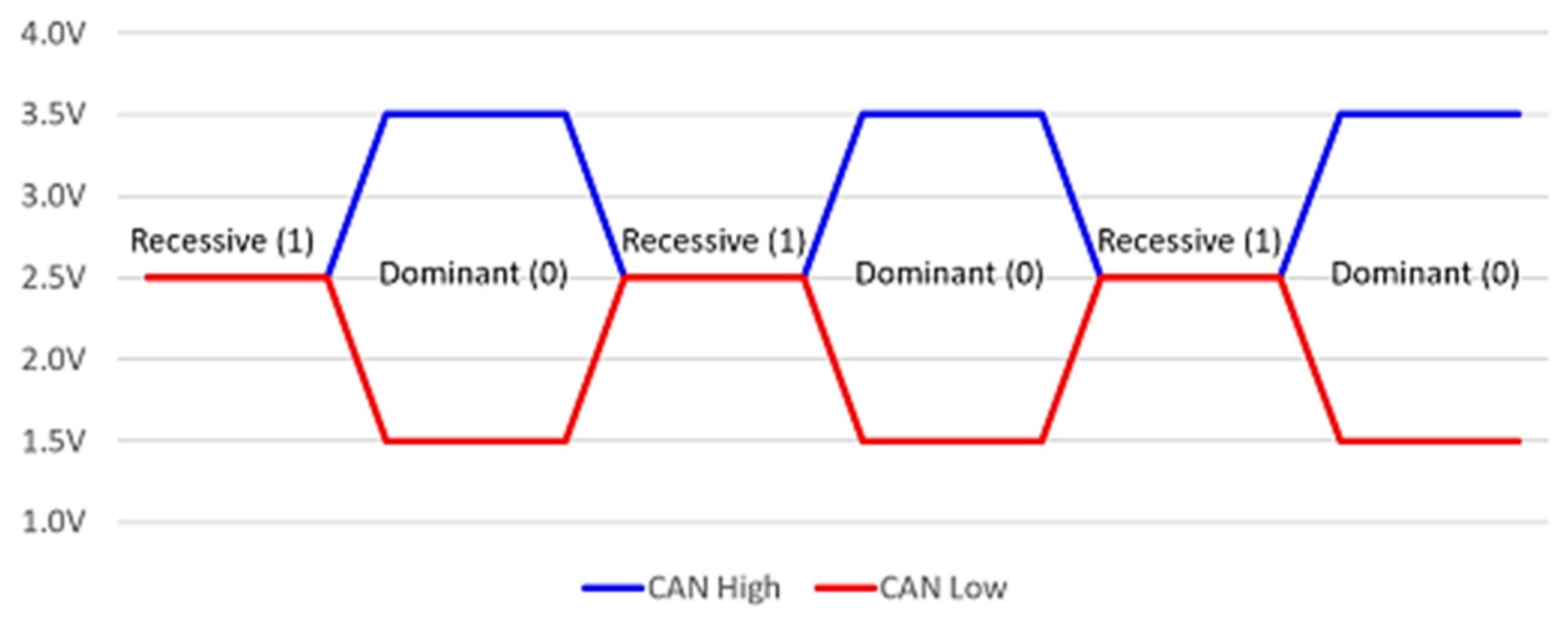
Figure 7.
CAN Bus wiring.
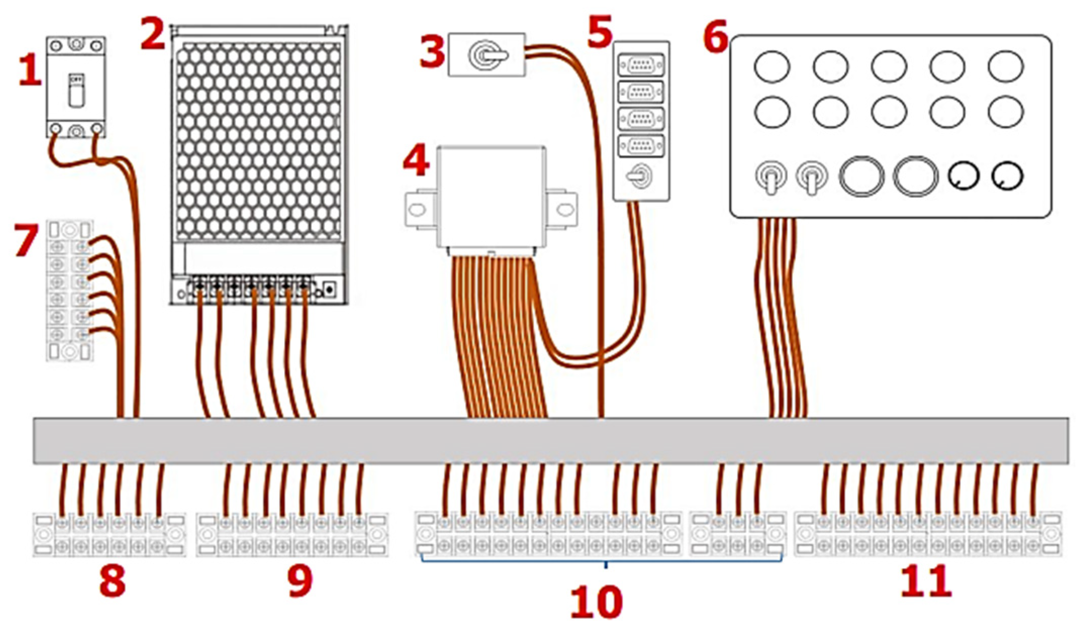
Figure 8.
Control Software: (a) MRS Developer Studio Software; (b) Graphical programming.
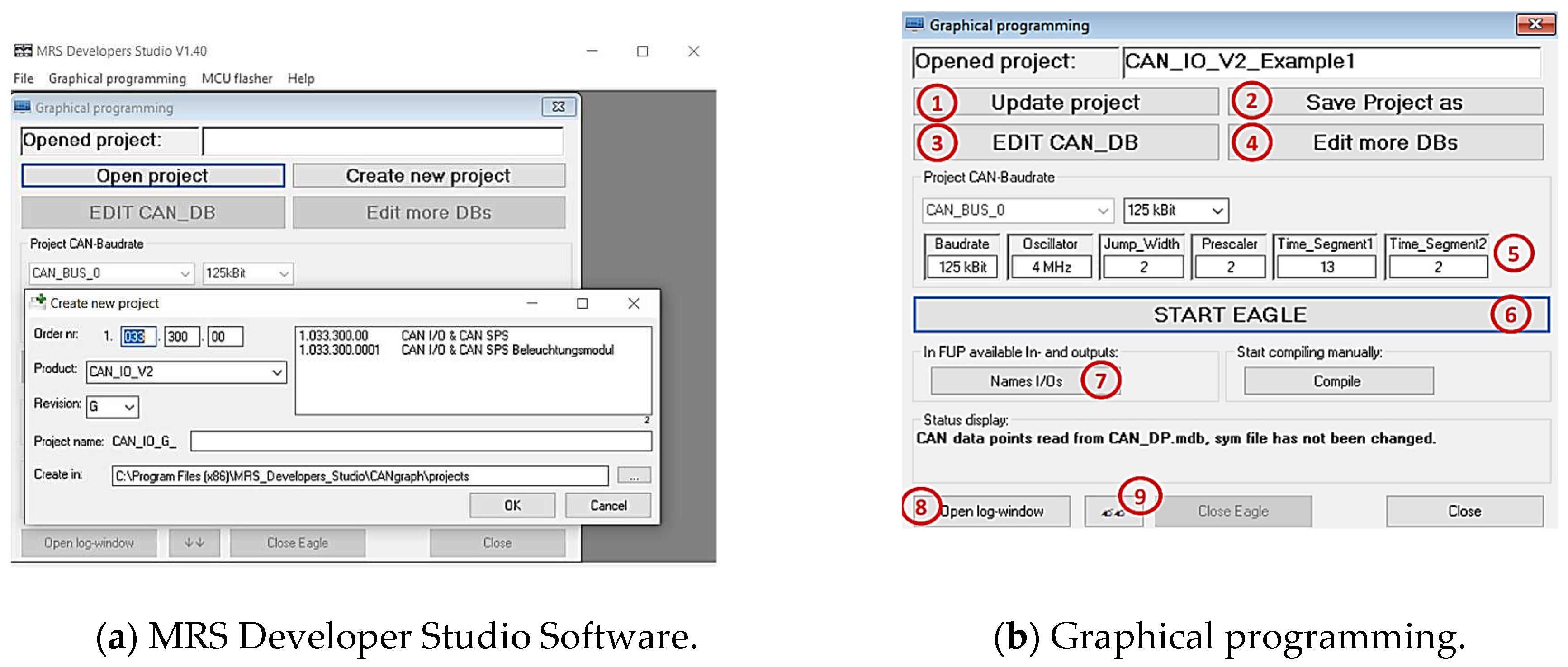
Figure 9.
CAN data base (CAN_DB).
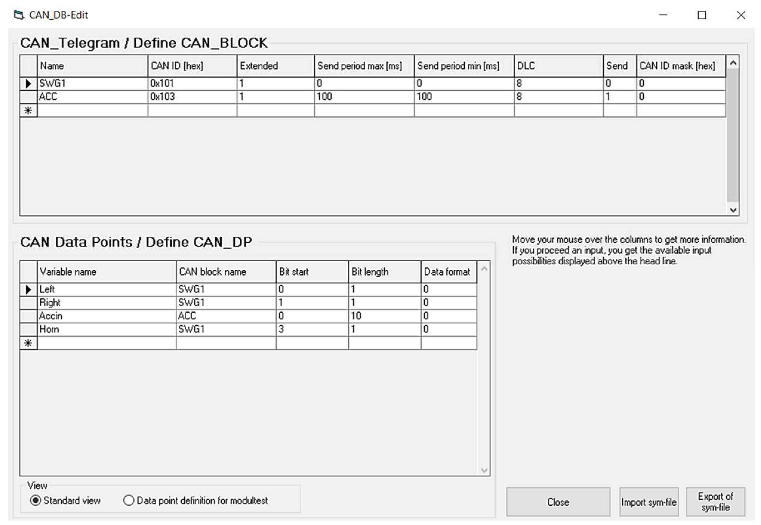
Figure 10.
Variables used to assist in writing A&D pins.
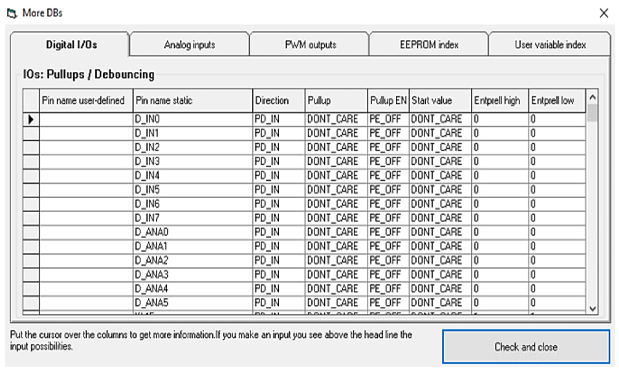
Figure 11.
Logic control: (a) The logic for the turn signal uses a 200 msec pulse signal (Send); (b) The logic for horn signal; (c) The logic for the turn signal; (d) The logic for creating an electric accelerator signal for PWM.
Figure 11.
Logic control: (a) The logic for the turn signal uses a 200 msec pulse signal (Send); (b) The logic for horn signal; (c) The logic for the turn signal; (d) The logic for creating an electric accelerator signal for PWM.
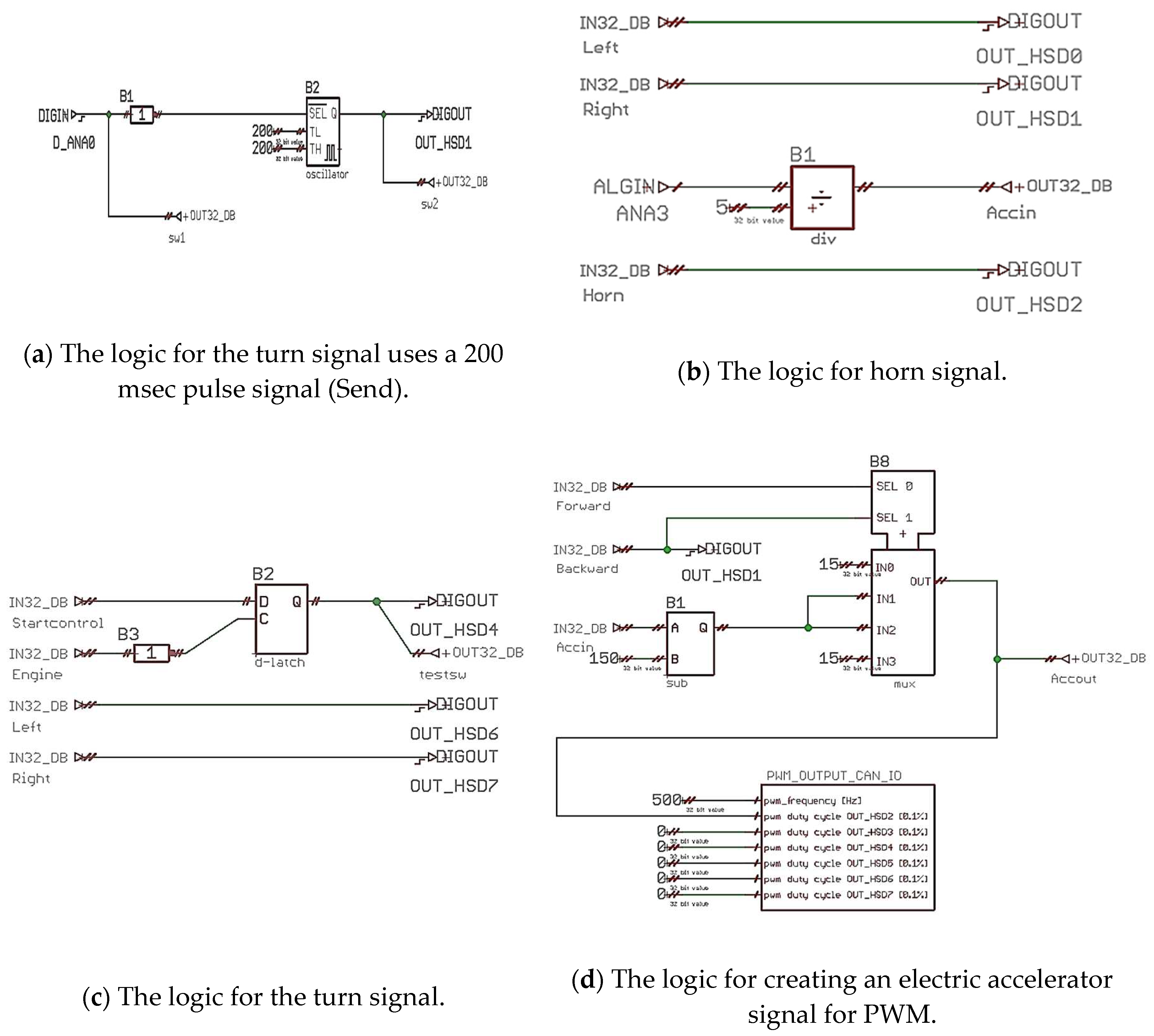
Figure 12.
Communication in Electric Vehicles.
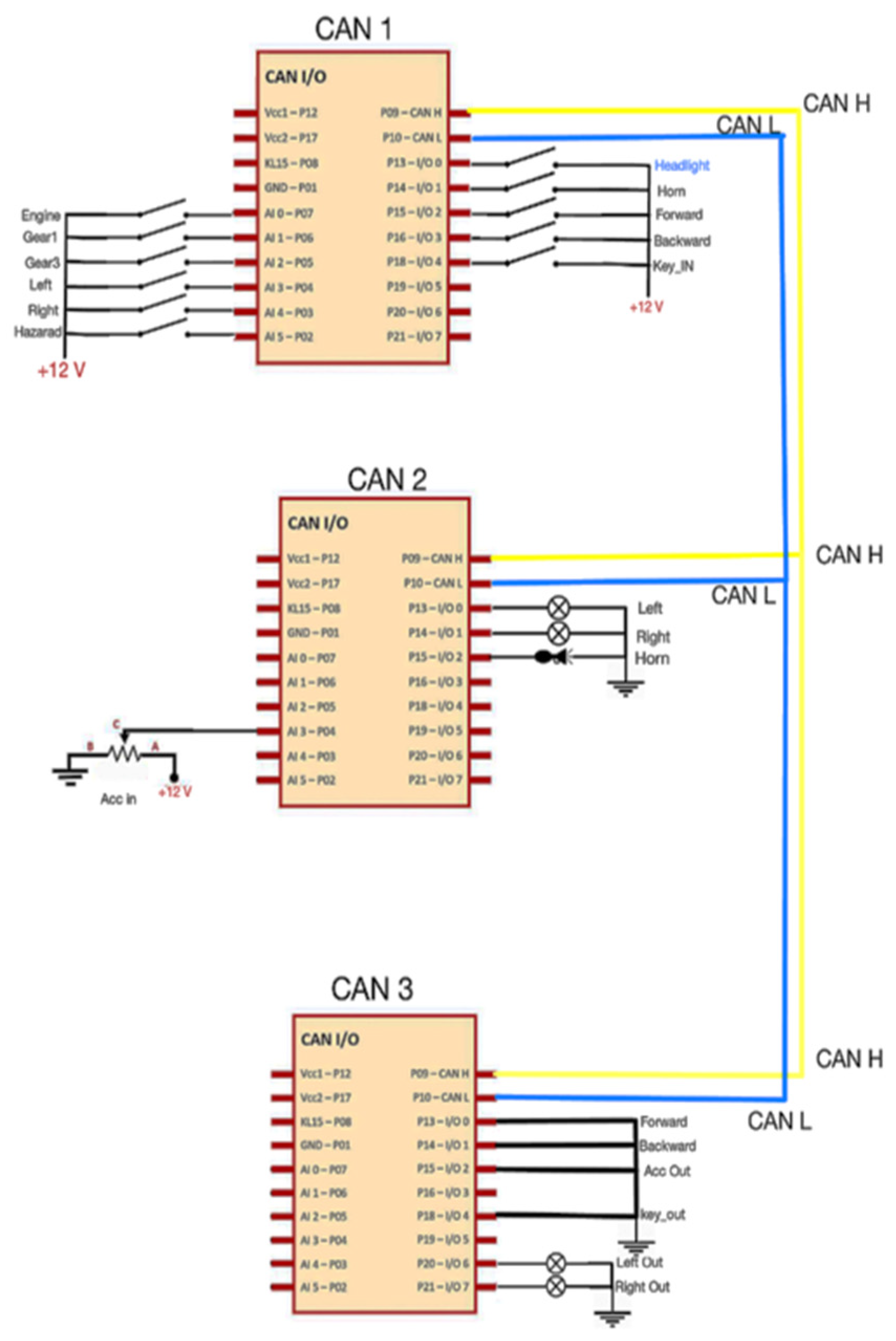
Figure 13.
Mechanical Structures of electric vehicle.
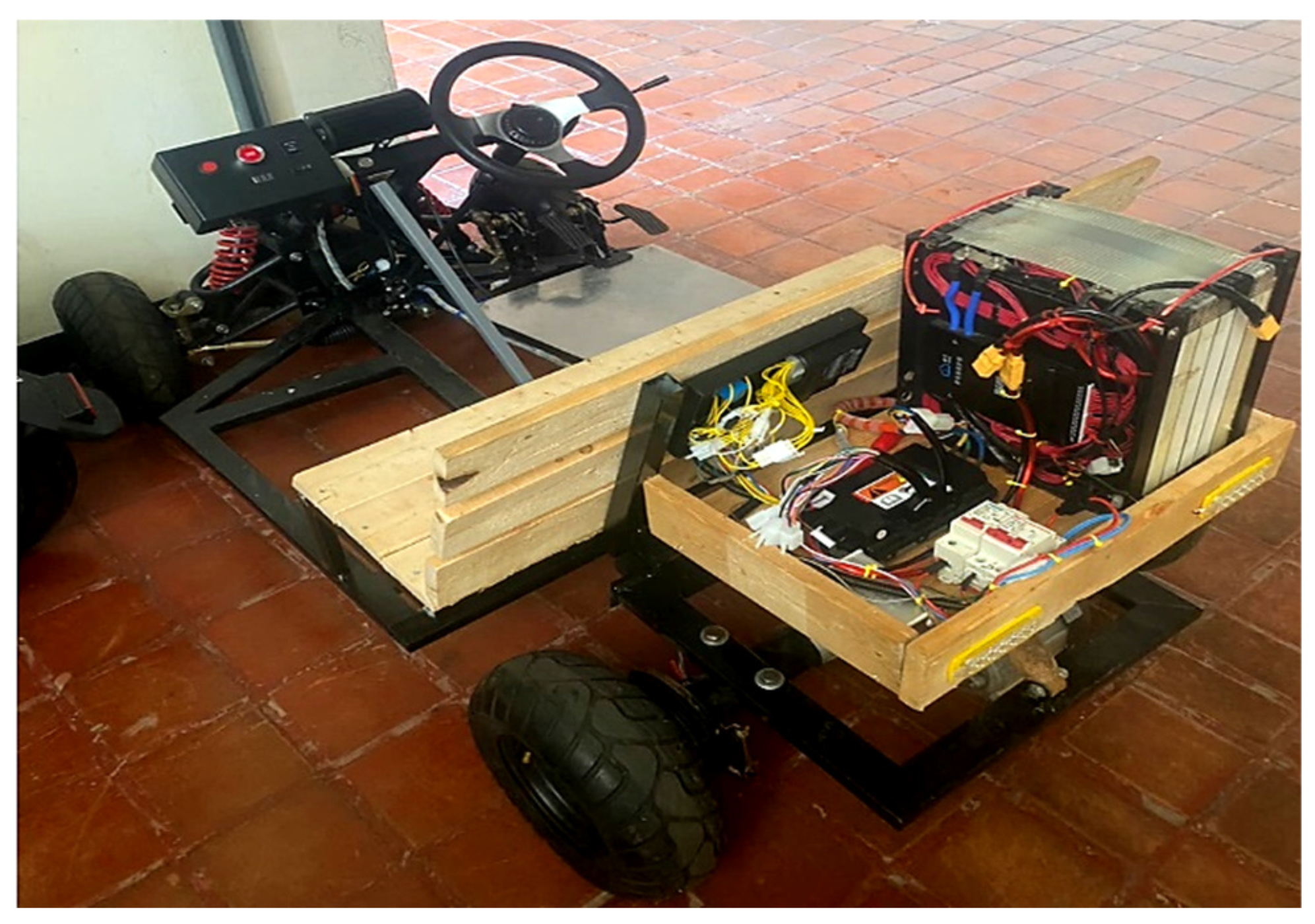
Figure 14.
Testing communication status: (a) Switches; (b) Headlight; (c) Turn signal; (d) Brake light; (e) Emergency light; (f) Horn; (g) Forward-Reverse gear; (h) Electric Accelerator.
Figure 14.
Testing communication status: (a) Switches; (b) Headlight; (c) Turn signal; (d) Brake light; (e) Emergency light; (f) Horn; (g) Forward-Reverse gear; (h) Electric Accelerator.
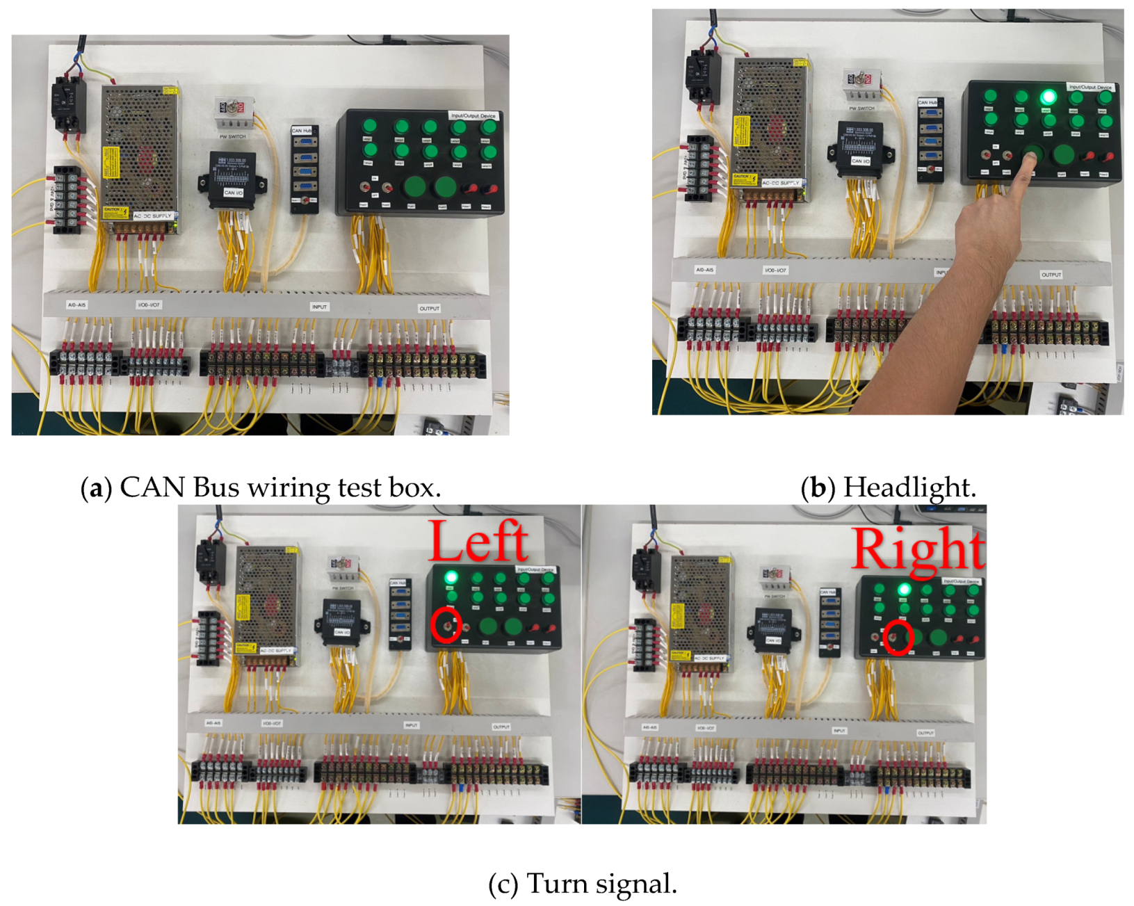
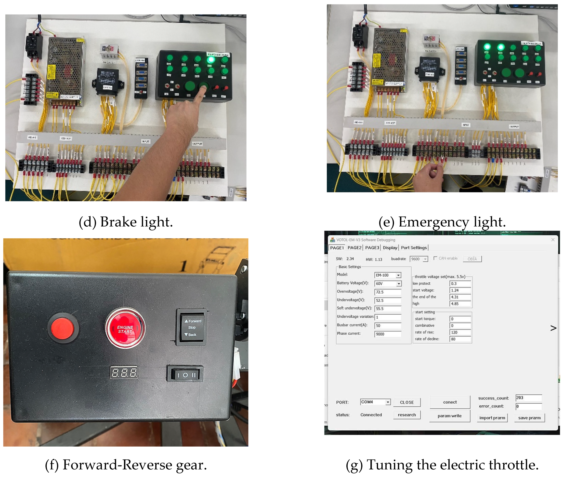
Figure 15.
Parameter of Battery Pack.
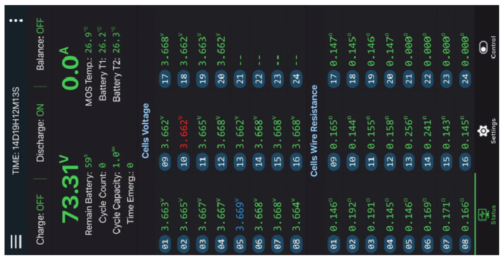

Table 1.
Materials and Equipment for Communication in Electric Vehicle Systems Using CAN Bus.
| Materials and Equipment | Units |
|---|---|
| Push Button Start | 1 |
| Electric car headlights | 1 |
| Klaxon (Horn) | 1 |
| Front turn signal | 2 |
| Back turn signal | 2 |
| CAN connector line | 2 |
| CAN Controller Box | 3 |
| DC to DC Step down (72V to 12V) | 1 |
| Battery Pack 72 V (Li-ion: NMC) | 1 |
| Motor DC 1500W 60V | 1 |
Table 2.
Materials and equipment for CAN Bus test box.
| Number | Materials and Equipment |
|---|---|
| 1 | Circuit Breaker |
| 2 | AC/DC switching |
| 3 | Power Switch |
| 4 | CAN I/O |
| 5 | The CAN hub |
| 6 | Input/output Device |
| 7 | +24V and Gnd. Terminal |
| 8 | Analog Inputs Terminal of CAN I/O |
| 9 | Input/output Terminal of CAN I/O |
| 10 | Input Terminal of input/output device |
| 11 | Output Terminal of input/output device |
Table 3.
CAN-block definition.
| Header | Description |
|---|---|
| Name | Name of the CAN-Block |
| CAN ID [hex] | CAN-Identifier from CAN-Block in [hex] |
| Extended | 0 is 11 bits identifier, 1 is 29 bits identifier |
| Send period max | Time of send period max |
| Send period min | Time of send period min |
| Data length | Length of the CAN frame data in byte |
| Send | 0 is CAN-Block received the CAN bus1 is CAN-Block send to the CAN bus |
| CAN ID mask | When you want to listen to variable CAN ID information. (EX: 0x10F, 0x100, ...) |
Table 4.
CAN-data definition.
| Header | Description |
|---|---|
| Variable name | Name of the data point |
| CAN block name | Definition of linked CAN-block (Write down in which CAN-block the variable is to be found) |
| Bit start | 0 ... 63, start position of the data into the CAN frame data area |
| Bit length | Length of the information in bits |
Table 5.
Testing communication of the CAN Bus system.
|
Testing CAN Bus communication |
Testing (Counts) | ||
| 1 | 100 | 1000 | |
| Switches | ✓ | ✓ | ✓ |
| Headlights | ✓ | ✓ | ✓ |
| Turn signal | ✓ | ✓ | ✓ |
| Brake light | ✓ | ✓ | ✓ |
| Emergency light | ✓ | ✓ | ✓ |
| Horn | ✓ | ✓ | ✓ |
| Forward-Reverse gear | ✓ | ✓ | ✓ |
| Electric Accelerator | ✓ | ✓ | ✓ |
Disclaimer/Publisher’s Note: The statements, opinions and data contained in all publications are solely those of the individual author(s) and contributor(s) and not of MDPI and/or the editor(s). MDPI and/or the editor(s) disclaim responsibility for any injury to people or property resulting from any ideas, methods, instructions or products referred to in the content. |
© 2023 by the authors. Licensee MDPI, Basel, Switzerland. This article is an open access article distributed under the terms and conditions of the Creative Commons Attribution (CC BY) license (http://creativecommons.org/licenses/by/4.0/).
Copyright: This open access article is published under a Creative Commons CC BY 4.0 license, which permit the free download, distribution, and reuse, provided that the author and preprint are cited in any reuse.


