
Submitted:
30 January 2024
Posted:
31 January 2024
Read the latest preprint version here
Abstract
Here we propose a simple way in which one can considerably improve performance of the gas stripper setup at the GSI UNILAC. To do so, it will be enough to replace inside the main GSI stripper chamber the present nozzle and the short windowless storage gas cell (for pulsed gas-jet operation mode) by a simple conical diverging nozzle combined with a gas catcher tube placed on the axis of gas-jet at some distance downstream the nozzle exit. As a result, the background pressure in the main and differentially pumped adjacent vacuum chambers of the gas stripper at the GSI UNILAC will dramatically reduce, and it will make possible to achieve the required optimal thickness of gas targets. The pulsed gas stripper operation is simply realized by implementing a commercially available fast gas valve connected to the nozzle entrance. Moreover, the ion beam pulses repetition rate can be increased and it will allow for the considerably higher average intensity of the ion beams extracted from the GSI UNILAC. Performance of the proposed GSI UNILAC gas stripper modification we explored by means of detailed computer experiments, which give a realistic description of supersonic gas jets flowing out the nozzle into vacuum. Results of these computer experiments have presented and discussed.
Keywords:
GSI UNILAC
; gas jet stripper
; supersonic nozzle
; gas catcher tube
; gas dynamic simulations
1. Introduction
An ion charge stripping system is one of the key component of high-intensity heavy-ion beams accelerator facilities: FRIB (MSU, USA) [1], RIBF (RIKEN, Japan) [2] and the future Facility for Antiproton and Ion Research (FAIR, Germany) [3].
In this article, we propose a simple way in which one can considerably improve performance of the gas stripper setup at the GSI UNILAC. The detailed description of the design and operation of the GSI gas stripper reader can find elsewhere, for example, in [4,5,6,7,8,9,10,11,12,13,14] and links within them. That is why we give here only its short description.
Schematic layout of the UNILAC with the gas stripper section shown in Figure 1 of Ref. [4]. The following ion sources are used at GSI for production of high-intense heavy ion beams:
Penning Ion Source (PIG) for ion beams of intermediate charge state (with ion pulses length up to 6 ms and a maximum repetition rate of 50 Hz);
Multi Cusp Ion Source (MUCIS) for gaseous elements (with ion pulses length up to 3 ms and a maximum repetition rate of 17 Hz);
Metal Vapor Vacuum Arc (MEVVA) source for metallic ions. (with ion pulses length up to 3 ms and a maximum repetition rate of 17 Hz).
Electron Cyclotron Resonance (ECR) source for highly charged ions (with ion pulses length up to 6 ms and a maximum repetition rate of 50 Hz.
The ion beam having +4 charge state after its acceleration up to the energy of 1.4 MeV/u enter into the gas stripper where ions cross a gas target. In result of a number of charge-exchange ions’ collisions with atoms of the gas target, charge states of ions are increased. Then the beam of highly charged ions undergo a charge selection passing fast switchable dipole magnets and its part having desired charge state is injected into a subsequent accelerating Alvarez-type section. Here the selected ion beam accelerates up to the final energy of 11.4 MeV/u.
There are two following gas stripper variants are used at the GSI UNILAC.
- First variant consists in operation with the continuous nitrogen gas jet flowing out the conical supersonic nozzle into the main stripper chamber (the 3D schematic of this setup one can see in Figure 2 in Ref. [12]). The nozzle throat diameter is 0.85 mm, the length of supersonic diverging part is 13.85 mm and the exit nozzle diameter is 5 mm. The gas from the main stripper chamber is evacuated by Roots vacuum pump having capacity of 8000 m3/h (or 2222 l/s). Four subsidiary vacuum chamber serve as a differential pumping system (two chamber in front of the stripper and two chamber behind it). Each of these subsidiary chambers pumped by separate Turbomolecular vacuum pump of 1200 l/s. The ion beam cross the supersonic jet at right angle to its axis.
- In the second gas stripper variant the supersonic nozzle has replaced by the pulsed gas valve, which exit aperture directly connected to the T-fitting aligned with the ion beam axis (see it in Figure 2 in Ref. [11]). This short T-fitting has length of 44 mm in the ion beam direction and 21 mm aperture. The 3D schematic of this pulsed gas stripper setup shown in Figure 1 in Ref. [11] and in Figure 2 in Ref. [14].
Characteristics of ion beams passed through the gas stripper section of the GSI UNILAC presented in Figures 3, 4 and 5 in Ref. [14]. So, Figure 3 shows charge state distributions of uranium ions stripped in nitrogen continuous jet and by helium and hydrogen in pulsed operation mode. Figure 4 demonstrates charge state distributions for stripped uranium ions for different hydrogen target thickness and Figure 5 shows equilibrated charge state distributions for 238U, 209Bi, 50Ti, and 40Ar ions passed through nitrogen and hydrogen gas targets.
It is of common knowledge that main limiting factor in the use of any internal gas target in accelerator technology and accelerator experiments is a deterioration of background vacuum in the course of these targets operation. That is why the gas stripper at the GSI UNILAC can be used with the nitrogen continuous supersonic jet only when the gas stagnation pressure in the nozzle not higher than 4 bar.
The gas stripper at the GSI UNILAC operates with hydrogen in pulsed mode with the low ion beam pulse repetition rate (gas pulses are synchronized with ion pulses) about of 3 Hz. Another disadvantage of the pulse stripper design at the GSI is that the gas flows out of both ends of the short T-fitting in form of a pulsed supersonic jet in the direction of the ion beam (see Figure 1 in Ref. [11]). This can lead to additional vacuum deterioration in adjacent differential pumping chambers.
We sure that in order to considerably reduce background pressures in vacuum chambers of the gas stripper at the GSI UNILAC and thus significantly improve its performance, it will be sufficient just to install downstream the supersonic nozzle a gas catcher tube having a conical entrance part. The distance between the nozzle exit and this gas catcher entrance determined by the ion beam diameter. In result, main part of the gas flowing out the nozzle into the main stripper' vacuum chamber will be evacuated through this gas catcher tube.
The gas catcher tube and the supersonic nozzle are located vertically on the axis of main stripper chamber. The output end of the gas catcher tube is fixed in the center of top flange, which is similar to the existing one (see Figure 2 in Ref. [11]). The supersonic nozzle exit is located below horizontal ion beam axis. For gas pumping out of the gas catcher tube, it will be enough to connect its output through some flexible bellow with a relatively small additional Roots pump of 251 m3/h pumping capacity.
In other words, for upgrade of the present gas stripper at the GSI UNILAC we suggest to use a classic design-concept of internal gas jet targets, where the supersonic nozzle and gas catcher are key components. Internal gas jet targets known more than 30 years and are wildly used nowadays in various accelerator experiments.
Descriptions of various internal gas jet targets reader can find e.g. in reviews [15,16] and original works [17,18,19,20,21,22,23]. It is worth noting here that in order for the GSI UNILAC gas stripper upgraded in the described manner could work in the pulse mode with light gases (helium and hydrogen), it is enough to connect a commercially available fast pulsed valve to the entrance of supersonic nozzle. For example, this could be a pulse valve, presented in [24] and successfully used in our works [22] and [23]. To switch to the mode of continuous gas-jet operation, one need just to keep the valve opened.
Performance of the proposed GSI UNILAC gas stripper modification we explored by means of detailed computer experiments with the use of VARJET code. This code, described in detail in [25], has based on the solution of a full system of time dependent Naier–Stokes equations. It gives a realistic description of supersonic and subsonic gas jets flowing out the nozzle into vacuum. Many times during last 20 years, it has been confirmed by direct comparison of our simulations with measurements for different applications. Results of similar computer experiments for the gas stripper have presented and discussed in the next sections.
2. Results for continuous nitrogen jet
In order to demonstrate an advantage of the gas stripper equipped with gas catcher tube over the present GSI UNILAC stripper (variant #1) with the supersonic nozzle we made following five computer simulations for continuous nitrogen gas jet:
- GSI nozzle (the nozzle throat diameter is 0.85 mm, the length of supersonic diverging part is 13.85 mm and the nozzle’ exit diameter is 5 mm) at 4 bar stagnation pressure.
- GSI nozzle + gas catcher at 4 bar stagnation pressure.
- New nozzle + gas catcher (the nozzle throat diameter is 1.0 mm, the length of supersonic diverging part is 40 mm and the nozzle’ exit diameter is 8 mm) at 4 bar stagnation pressure. This long and narrow new nozzle we recommend for the using with gas catcher tube in the upgraded gas stripper at the GSI.
- GSI nozzle + gas catcher at 10 bar stagnation pressure.
- New nozzle + gas capture at 10 bar stagnation pressure.
Figure 1 and Figure 2 show for illustration results of gas dynamic simulations of nitrogen density flow field for the 1st and 2nd calculation variants, correspondingly.
The gas catcher tube (see it in Figure 2), that installed on the gas jet axis at 21 mm distance downstream the nozzle exit, have a conical entrance part of 28 mm length with entrance and exit inner diameters of 40 mm and of 50 mm, correspondingly. The thickness of the catcher tube wall does not important. The 21 mm gap between the nozzle and gas catcher tube is equal to the aperture of the T-fitting shown in Figure 2 in Ref. [11].
Result of gas dynamic simulation of nitrogen density flow field for the 3rd calculation variant shown in Figure 3. Notice that a disk of 40 mm outer diameter fixed to the nozzle exit as it shown in Figure 3. The thickness of this disk as well as its outer diameter are not critical.
Figure 4 shows results of calculations for nitrogen target thickness as a function of distance from the nozzle exit for five mentioned above calculation variants. Main calculated gas flow characteristics for these five variants of the gas stripper operation listed in Table 1.
Note that a slower slope of target thickness curves for the new nozzle (see Figure 4) means better thickness homogeneity of these gas targets
Difference of the total gas flow rates for variants #2 and #3, as well as for #4 and #5, simply explained by the difference in throat diameters of the present “GSI nozzle” (0.85 mm) and the “New nozzle” (1.0 mm).
3. Results for pulsed gas jet stripper operation mode
In order to find out how the geometry of a supersonic nozzle affects performance of the gas stripper in the pulse operation mode, we performed gas dynamic calculations for conical diverging nozzles having different outlet diameters and lengths at fixed nozzle throat diameter of 1.0 mm. The calculations have been made for jets of nitrogen, helium and hydrogen.
3.1. Helium pulsed jet target
Figure 5 shows the result of calculation for the time profile of the averaged helium target thickness. The gas valve opens at zero time and closes after 150 µs. The gas pulse has a long flattop which duration is enough for an effective stripping of the pulsed ion beam of 100 µs duration.
It should notice, that here it is supposed that the pulsed valve is fully opened instantly (without any delay). In reality, it is not true due to a finite velocity movement of the valve' poppet at opening. However, this is not a problem to make a proper synchronization of the gas and ion beam pulses.
Result of the gas dynamic simulation of helium density flow field at 100 µs after the valve opening shown in Figure 6 for illustration.
The quasi-equilibrium background gas pressure Pbg in the main stripper chamber is determined as the following:

where G – is the instant mass gas flow rate into the main stripper chamber at ~100 µs after the valve opening in [mbar l/s], f – is the ion pulse repetition rate in [Hz], τ – is the gas pulse duration in [s] and S - is the pumping speed of the main stripper chamber in [l/s].
Here we consider the case of the maximum possible ion beam repetition rate f = 50 Hz, τ = 200 µs and S =2222 l/s (the present Roots pump at the GSI UNILAC).
The gas catcher efficiency of helium pulsed jet evacuation and the averaged helium target thickness for nozzles having different lengths and outlet diameters listed in Table 2 and Table 3, correspondingly.
Figure 7 shows results of calculations of the pulsed helium target thickness as a function of distance from the nozzle exit for the nozzles having different outlet diameters (D) at the fixed nozzles length L = 40 mm.
Figure 8 shows results of calculations of the pulsed helium target thickness as a function of distance from the nozzle exit for the nozzles having different lengths (L) at the fixed nozzles outlet diameter D = 8 mm.
3.2. Hydrogen pulsed jet target
Figure 9 shows result of calculation for the time profile of the averaged hydrogen target thickness. The gas valve opens at zero time and closes after 140 µs.
Result of the gas dynamic simulation for hydrogen density flow field at 100 µs after the valve opening shown in Figure 10 for illustration.
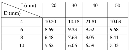
The gas catcher efficiency for hydrogen pulsed jet evacuation and the averaged hydrogen target thickness for nozzles having different lengths and outlet diameters listed in Table 4 and Table 5, correspondingly.
Figure 11 shows results of calculations for of the pulsed hydrogen target thickness as a function of distance from the nozzle exit for the nozzles having different outlet diameters (D) at the fixed nozzles length L = 40 mm.
Figure 12 shows results of calculations for of the pulsed hydrogen target thickness as a function of distance from the nozzle exit for the nozzles having different lengths (L) at the fixed nozzles outlet diameter D = 8 mm.
3.3. Effect of the gap value between the nozzle exit and the gas catcher tube entrance
To show how the gas target thickness depend on the gap between the nozzle exit and the gas catcher tube entrance we have made gas dynamic simulation for the gap value of 30 mm.
The result of this calculation for pulsed hydrogen jet at P0 = 25 bar (the nozzle length L = 40 mm, exit diameter D = 8mm) shown in Figure 13. The result of calculation for the gap of 21 mm (red solid line) shown here for comparison.
Notice that the both curves (the red solid and blue dashed lines) are coincide. This is simply because the disturbance in the supersonic jet caused by its interaction with the gas catcher cannot propagate upstream.
It is due to the same reason the gas target thickness do not depends on the diameter of gas catcher entrance. To confirm it, we have made additional calculations for the gas catcher tube entrance diameters of D = 30 mm and D = 50 mm. But the gas catcher efficiency for the case of D = 30 mm is 87.6 % that 5.8 % less compared to the catcher with D = 40 mm (see Table 4). It also means that a gas load into the main stripper chamber for the case of D = 30 mm in a factor of 2 higher compared to that one for the catcher tube with the entrance diameter of 40 mm.
3.4. How the gas target thickness depends on the stagnation pressure P0
To show how the gas target thickness depends on the stagnation pressure P0 we have made corresponding gas dynamic simulations for pulsed nitrogen, helium and hydrogen supersonic jets.
Figure 14 shows result of calculation for the time profile of the averaged nitrogen target thickness. The gas valve opens at zero time and closes after 300 µs.
Figure 15 show the results of calculations of the pulsed nitrogen target thickness as a function of distance from the nozzle exit for different stagnation pressures. The gas catcher efficiencies for 10 bar and 20 bar are equal to the 90.3 % and 89.8 %, correspondingly.
Figure 16 and Figure 17 show the results calculations of the pulsed helium and hydrogen targets thickness as a function of distance from the nozzle exit for different stagnation pressures. The gas catcher tube efficiencies for stagnation pressures of 50 bar and 75 bar are near the same as it is for the described above case of 25 bar stagnation pressure.
4. Discussion and outlook
In our opinion, the authors and developers of the GSI gas stripper made two big conceptual mistakes.
The first mistake has been made at the very beginning of the gas stripper development, when they decided that near to all gas flowing out the supersonic nozzle should be removed from the main stripper chamber by the Roots vacuum pump of 8000 m3/h. However, long before this, there were various internal gas jet targets setups, in which supersonic gas flow, after its crossing with the ion beam was removed from the target vacuum chamber using the gas catchers of different design. These setups are well known and described, for example, in reviews [15,16] and original articles [18,21]. Notice that the work [21] published in 1997 describes the internal gas target, which it is still in operation at the ESR GSI.
The second big mistake authors of the gas stripper at the GSI UNILAC have made about 10 years ago at the transition to the operation of a gas stripper in pulsed mode. It was then decided to abandon the use of a supersonic nozzle, but simply use the pulse valve directly connected to the short T-fitting aligned with the ion beam axis. A short description of this pulsed gas stripper version we presented above in the Introduction section.
Despite of significant advantage of the using the gas stripper in pulse mode, this particular design solution, which currently in use at the GSI UNILAC, suffers from the same disadvantage associated with vacuum limitation. An additional serious drawback of this design is that the gas flows out the T-fitting in the direction of apertures of adjacent differential pumping chambers (see Figures 1 and 2 in Ref. [11]) in form of pulsed supersonic jets. Therefore, we think that it would be better simply continue the use the gas stripper with supersonic nozzle, providing it with a fast pulse valve. Moreover, an opening time duration of the valve required for effective operation with ion pulses of 100 µs could then be less.
In this article, we propose a simple way in which one can considerably improve performance of the gas stripper setup at the GSI UNILAC. It consists in the use of classic and wellknown design concept of internal gas jet targets. In the case of th gas stripper at the GSI UNILAC the gas jet catcher tube is installed at some downstream distance from the supersonic nozzle exit. This distance (or the gap between the nozzle exit and gas catcher tube entrance) mainly determined by the size of the ion beam crossing the gas jet at right angle.
Performance of the proposed GSI UNILAC gas stripper modification we explored by means of detailed computer experiments, which give a realistic description of supersonic gas jets flowing out the nozzle into vacuum.
We recommend using a simple conical supersonic diverging nozzle having the throat diameter, length and exit diameter of 1 mm, 40 mm and 8 mm, correspondingly.
For entrance diameter of the conical part of the gas catcher tube, we recommend the value of 40 mm.
To evacuate the gas out of the gas catcher tube it will be enough to use an additional relatively small Roots pump of 251 m3/h.
The calculated gas catcher efficiencies in the pulse operation mode are about 98% for helium and 93% for hydrogen. It allows dramatically decrease the background pressure in the main stripper vacuum chamber and, in result, increase the use of higher than at present repetition rates of the ion beams.
We very hope that people in the GSI, who are responsible for the gas stripper operation at the GSI UNILAC, will follow our article’s recommendations in the course of the next and probably final upgrade of their gas stripper setup. This upgrade should not be expensive and time consuming.
Funding
This research received no external funding.
Data Availability Statement
The data presented in this study are available upon request from the author.
Conflicts of Interest
The author declare no conflict of interest
References
- T. Kanemura, J. Gao, M. LaVere, R. Madendorp, F. Marti, Y. Momozaki, PROGRESS OF LIQUID LITHIUM STRIPPER FOR FRIB, North American Particle Acc. Conf. NAPAC2019, Lansing, MI, USA (2019) 636-638. [CrossRef]
- H. Imao, H. Okuno, H. Kuboki, S. Yokouchi, N. Fukunishi, O. Kamigaito, H. Hasebe, T. Watanabe, Y. Watanabe, M. Kase, Y. Yano, CHARGE STRIPPING OF URANIUM-238 ION BEAM WITH HELIUM GAS STRIPPER, Proceedings of IPAC2012, New Orleans, Louisiana, USA (2012) 3930-3932.
- FAIR Baseline Technical Report, Vol. 2, GSI Darmstadt, Germany (2006), p. 335.
- J. Glatz, J. Klabunde, U. Scheeler, D. Wilms, Operational aspects of the high current upgrade UNILAC Proceedings of Linear Accelerator Conference, Monterey, U.S.A (2000) 232–234.
- W. Barth, P. Forck, The new gas stripper and charge state separator of the GSI high current injector, Proceedings of Linear Accelerator Conference, Monterey, U.S.A (2000) 235–237.
- P. Gerhard, M. Maier, ON THE UNILAC PULSED GAS STRIPPER AT GSI, 31st Int. Linear Accel. Conf. LINAC2022, Liverpool, UK, (2022) 258-261. [CrossRef]
- W. Barth, M. Miski-Oglu, U. Scheeler, H. Vormann, M. Vossberg, S. Yaramyshev, UNILAC HEAVY ION BEAM OPERATION AT FAIR INTENSITIES, 31st Int. Linear Accel. Conf. LINAC2022, Liverpool, UK (2022) 102-105. [CrossRef]
- W. Barth, A. Adonin, Ch. E. Düllmann, M. Heilmann, R. Hollinger, E. Jäger, O. Kester, J. Khuyagbaatar, J. Krier, E. Plechov, P. Scharrer, W. Vinzenz, H. Vormann, A. Yakushev, and S. Yaramyshev, High brilliance uranium beams for the GSI FAIR, PHYS. REV. ACCEL. BEAMS 20, 050101 (2017) 1-4. [CrossRef]
- W. Barth, R. Hollinger, A. Adonin, M. Miski-Oglu, U. Scheeler and H. Vormann, LINAC developments for heavy ion operation at GSI and FAIR, Journal of Instrumentation, 15 (2020) T12012. [CrossRef]
- Scharrer, E. Jäger, W. Barth, M. Bevcic, C. E. Düllmann, L. Groening, K.-P. Horn, J. Khuyagbaatar, J. Krier, and A. Yakushev, Electron stripping of Bi ions using a modified 1.4 MeV/u gas stripper with pulsed gas injection, J. Radioanal. Nucl. Chem. 305 (2015) 837-842. [CrossRef]
- P. Scharrer1, W. Barth, M. Bevcic, Ch. E. Düllmann, L. Groening, K. P. Horn, E. Jäger, J. Khuyagbaatar, J. Krier, A. Yakushev, Stripping of high intensity heavy-ion beams in a pulsed gas stripper device at1.4MeV/u, Proceedings of IPAC2015, Richmond, VA, USA (2015) 3773-3775.
- Winfried Barth, Aleksey Adonin, Christoph E. Düllmann, Manuel Heilmann, Ralph Hollinger, Egon Jäger, Jadambaa Khuyagbaatar, Joerg Krier, Paul Scharrer, Hartmut Vormann and Alexander Yakushev, U28+-intensity record applying a H2-gas stripper cell, Phys. Rev. ST Accel. Beams 18 040101 (2015) 1-9. [CrossRef]
- P. Scharrer1, W. Barth, M. Bevcic, Ch. E. Düllmann, P. Gerhard, L. Groening, K. P. Horn, E. Jäger, J. Khuyagbaatar, J. Krier, H. Vormann, A. Yakushev, Applications of the pulsed gas stripper technique at the GSI UNILAC, Nucl. Instrum. Methods Phys. Res. A 863 (2017) 20-25. [CrossRef]
- P. Gerhard, W. Barth, M. Bevcic, Ch. E. Düllmann, L. Groening, K. P. Horn, E. Jäger, J. Khuyagbaatar, J. Krier, M. Maier, P. Scharrer, A. Yakushev, DEVELOPMENT OF PULSED GAS STRIPPERS FOR INTENSE BEAMS OF HEAVY AND INTERMEDIATE MASS IONS, 29th Linear Accelerator Conf. LINAC2018, Beijing, China (2018) 982-987. [CrossRef]
- M. Macri, Gas Jet Internal Target, CERN Acceleration School – Antiprotons for Colliding Beam Facilities, Geneva, Switzerland, 1983, Report CERN 84-15 (1984), ed. P. Bryant and S. Newman, p. 469.
- C. Ekström, Internal targets - a review, Nucl. Instrum. Methods Phys. Res. A 362 (1995) 1-16. [CrossRef]
- J.E. Doskov, F. Sperisen, Development of internal jet targets for high-luminosity experiments, Nucl. Instr. and Meth. A 362 (1995) 20-25. [CrossRef]
- Antonios Kontos, Daniel Schürmann, Charles Akers, Manoel Couder, Joachim Görres, Daniel Robertson, Ed Stech, Rashi Talwar, Michael Wiescher, HIPPO: A supersonic helium jet gas target for nuclear astrophysics, Nucl. Instrum. Methods Phys. Res. A 664 (2012) 272–281. [CrossRef]
- Zach Meisela, Ke Shi, Aleksandar Jemcov, Manoel Couder, Exploratory investigation of the HIPPO gas-jet target fluid dynamic properties, Nucl. Instrum. Methods Phys. Res. A 828 (2016) 8–14. [CrossRef]
- K. Schmidt, K.A. Chipps, S. Ahn, D.W. Bardayan, J. Browne, U. Greife, Z. Meisel, F. Montes, P.D. O’Malley, W-J. Ong, S.D. Pain, H. Schatz, K. Smith, M.S. Smith, P.J. Thompson, Status of the JENSA gas-jet target for experiments with rare isotope beams, Nucl. Instrum. Methods Phys. Res. A 911 (2018) 1–9. [CrossRef]
- H. Reich, W. Bourgeois, B. Franzke, A. Kritzer, V. Varentsov, The ESR internal target, Nuclear Physics A 626 (1997) 417-425. [CrossRef]
- V.L. Varentsov, N. Kuroda, Y. Nagata, H. A. Torii, M. Shibata, and Y. Yamazaki, ASACUSA Gas-Jet Target: Present Status And Future Development, AIP Conference Proceedings 793 (2005) 328-340. [CrossRef]
- D. Tiedemann, K.E. Stiebing, D.F.A. Winters, W. Quint, V. Varentsov, A. Warczak, A. Malarz, Th. Stöhlker, A pulsed supersonic gas jet target for precision spectroscopy at the HITRAP facility at GSI, Nucl. Instrum. Methods Phys. Res. A 764 (2014) 387–393. [CrossRef]
- Parker Hannifin Corp. Available online: https://ph.parker.com/us/en/divisions/precision-fluidics-division-page/product/pulse-valves-miniature-high-speed-high-vacuum-dispense-valve/009-1669-900.
- V.L. Varentsov, A.A. Ignatiev, Numerical investigations of internal supersonic jet targets formation for storage rings, Nucl. Instrum. Methods Phys. Res. A 413 (1998) 447-456 . [CrossRef]
Figure 1.
Result of the gas dynamic simulation of nitrogen density flow field for present GSI nozzle. The stagnation pressure and temperature are P0 = 4 bar and T0 = 296 K, correspondingly. The calculated background pressure in the main stripper chamber Pbg = 0.17 mbar.
Figure 1.
Result of the gas dynamic simulation of nitrogen density flow field for present GSI nozzle. The stagnation pressure and temperature are P0 = 4 bar and T0 = 296 K, correspondingly. The calculated background pressure in the main stripper chamber Pbg = 0.17 mbar.
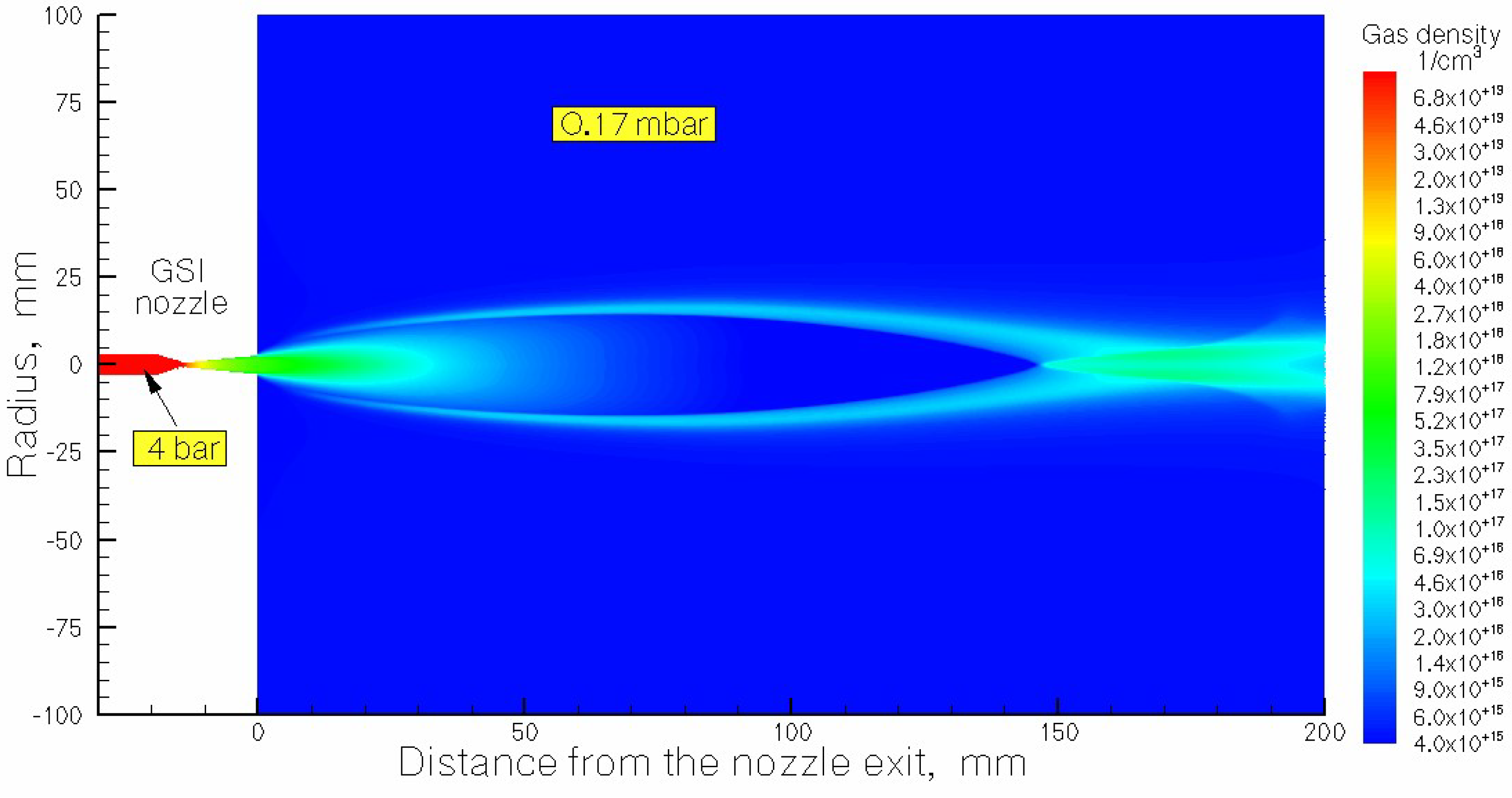
Figure 2.
Result of the gas dynamic simulation of nitrogen density flow field for the calculation variant #2: GSI nozzle + gas capture. The stagnation pressure and temperature are P0 = 4 bar and T0 = 296 K, correspondingly. Background pressure in the main stripper chamber Pbg = 0.02 mbar. Black arrowed lines show the gas flow directions.
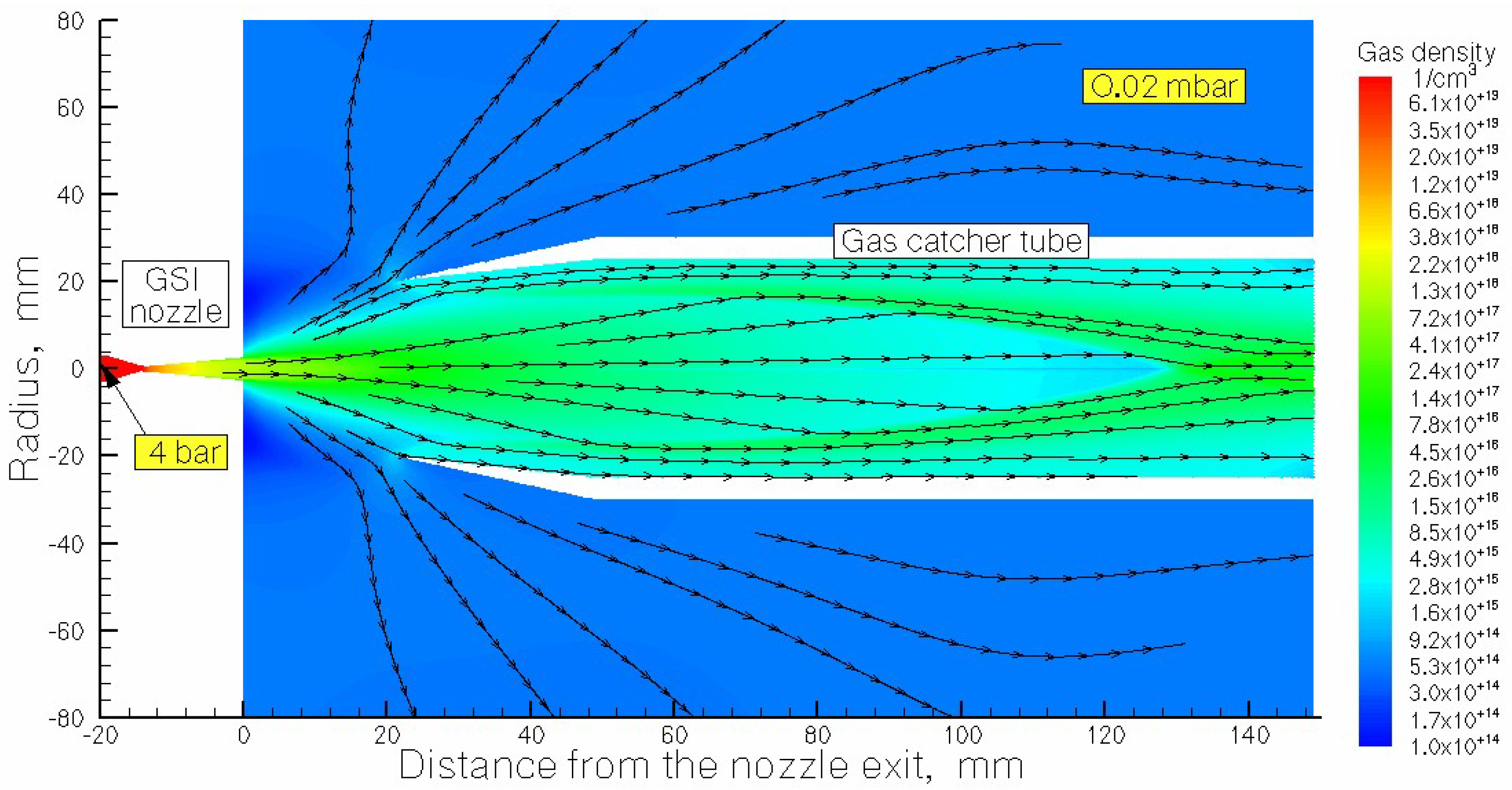
Figure 3.
Result of the gas dynamic simulation of nitrogen density flow field for the calculation variant #3: New nozzle + gas capture tube. The stagnation pressure and temperature are P0 = 4 bar and T0 = 296 K, correspondingly. Background pressure in the main stripper chamber Pbg = 0.03 mbar. Black arrowed lines show the gas flow directions.
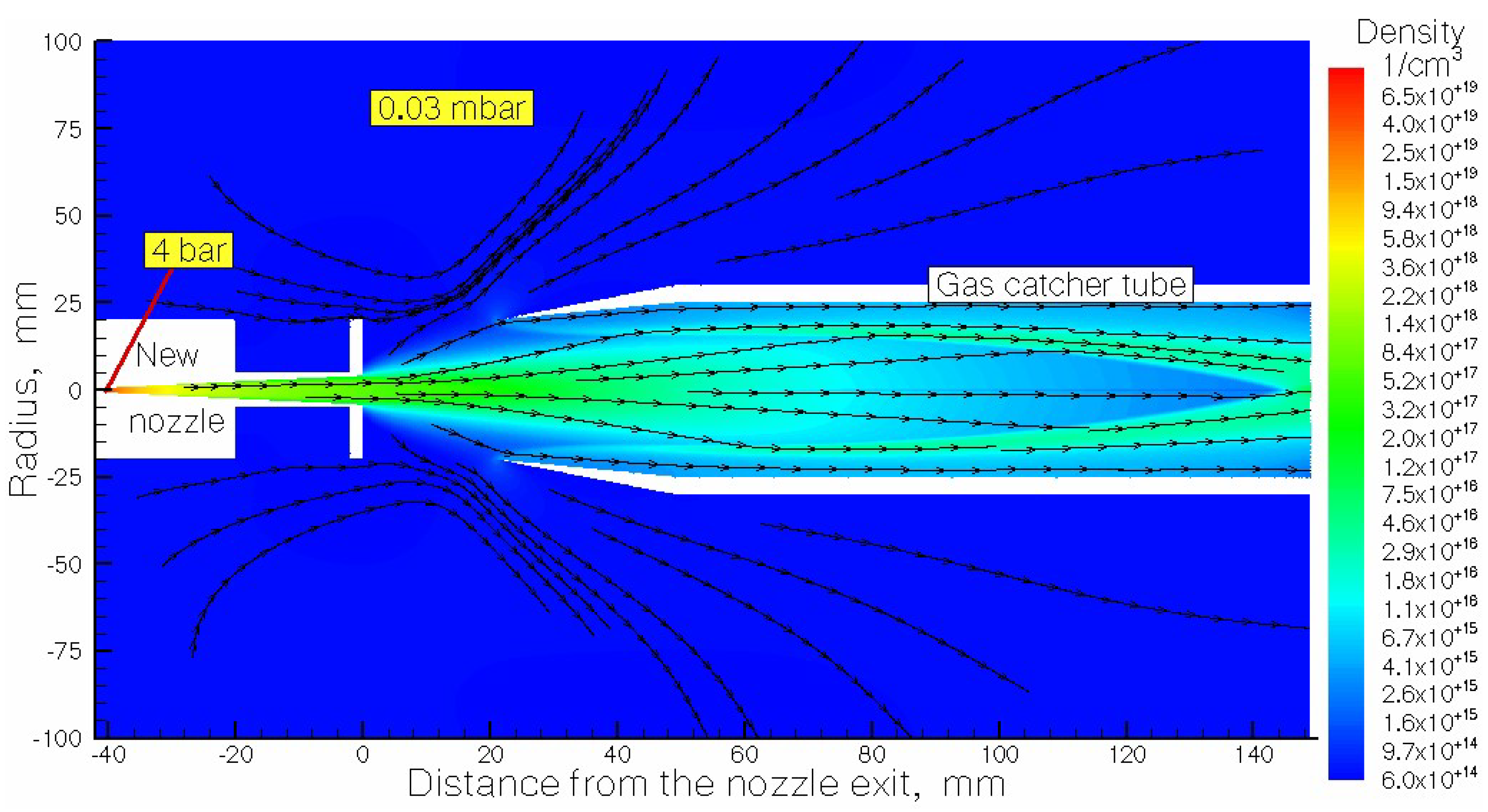
Figure 4.
Results of calculations for nitrogen target thickness as a function of distance from the nozzle for different variants of the stripper operation with continuous nitrogen gas jet. The nozzle temperature is T0 = 296 K for all calculation variants.
Figure 4.
Results of calculations for nitrogen target thickness as a function of distance from the nozzle for different variants of the stripper operation with continuous nitrogen gas jet. The nozzle temperature is T0 = 296 K for all calculation variants.
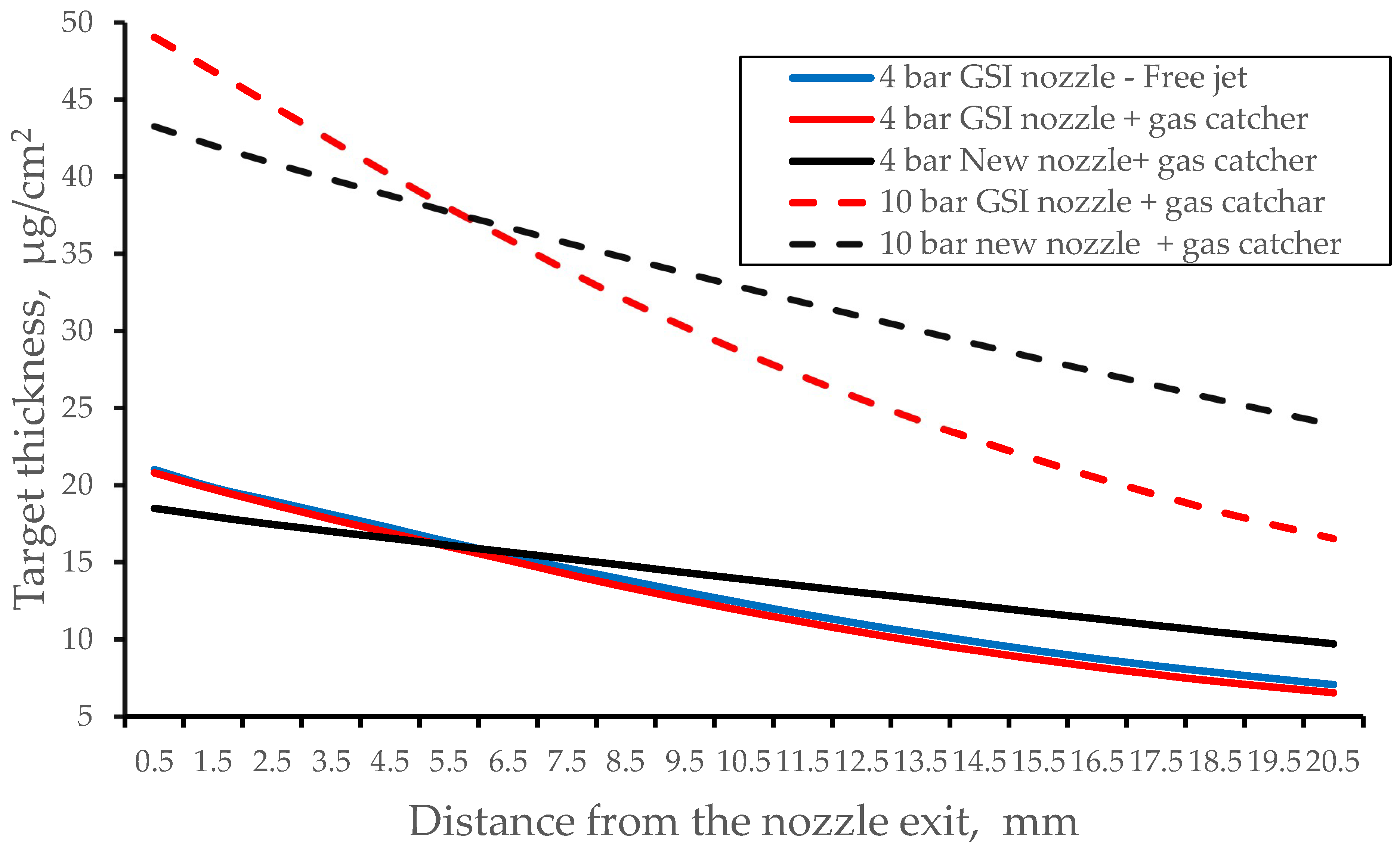
Figure 5.
Result of calculation for the time profile of the averaged helium target thickness. The gas valve opens at zero time and closes after 150 µs.
Figure 5.
Result of calculation for the time profile of the averaged helium target thickness. The gas valve opens at zero time and closes after 150 µs.
Figure 6.
Result of gas dynamic simulation of helium density flow field at 100 µs after the valve opening. The length of supersonic nozzle is 40 mm; its outlet diameter is 8 mm. The stagnation pressure and temperature are P0 = 25 mbar and T0 = 296 K, correspondingly. Quasi-equilibrium background gas pressure in the main stripper chamber Pbg = 0.001 mbar. Black arrowed lines show the gas flow directions.
Figure 7.
Results of calculations of the pulsed helium target thickness as a function of distance from the nozzle exit for the nozzles having different outlet diameters (D) at the fixed nozzle length L = 40 mm. The stagnation pressure P0 = 25 bar and the nozzle temperature T0 = 296 K for all calculation variants. Time after the valve opening is 100 µs.
Figure 8.
Results of calculations of the pulsed helium target thickness as a function of distance from the nozzle exit for the nozzles having different nozzles lengths (L) at the fixed nozzle outlet diameter D = 8 mm. The stagnation pressure P0 = 25 bar and the nozzle temperature T0 = 296 K for all calculation variants. Time after the valve opening is 100 µs.
Figure 9.
Result of calculation of the time profile of the averaged hydrogen target thickness. The gas valve opens at zero time and closes at time 140 µs.
Figure 9.
Result of calculation of the time profile of the averaged hydrogen target thickness. The gas valve opens at zero time and closes at time 140 µs.
Figure 10.
Result of the gas dynamic simulation for hydrogen density flow field at 100 µs after the valve opening. The length of supersonic nozzle is 40 mm; its outlet diameter is 8 mm. The stagnation pressure and temperature are P0 = 25 mbar and T0 = 296 K, correspondingly. Quasi-equilibrium background pressure Pbg in the main stripper chamber is 0.004 mbar. Black arrowed lines show the gas flow directions.
Figure 11.
Results of calculations of the pulsed hydrogen target thickness as a function of distance from the nozzle exit for the nozzles having different outlet diameters (D) at the fixed nozzles length L = 40 mm. The stagnation pressure P0 = 25 bar and the nozzle temperature T0 = 296 K for all calculation variants. Time after the pulsed valve opening is 100 µs.
Figure 12.
Results of calculations of the pulsed hydrogen target thickness as a function of distance from the nozzle exit for the nozzles having different nozzles lengths (L) at the fixed nozzles outlet diameter D = 8 mm. The stagnation pressure P0 = 25 bar and the nozzle temperature T0 = 296 K for all calculation variants. Time after the pulsed valve opening is 100 µs.
Figure 13.
Result of calculation of the pulsed hydrogen target thickness for the gap between the nozzle exit and gas catcher tube entrance of 30 mm. The nozzle length L = 40 mm, exit diameter D = 8mm. The stagnation pressure P0 = 25 bar and the nozzle temperature T0 = 296 K. The red solid line shows result of calculation for the gap of 21 mm for comparison. The time after the pulsed valve opening is 100 µs.
Figure 14.
Result of calculation of the time profile of the averaged nitrogen target thickness. The gas valve opens at zero time and closes after 300 µs.
Figure 14.
Result of calculation of the time profile of the averaged nitrogen target thickness. The gas valve opens at zero time and closes after 300 µs.
Figure 15.
Results of calculations of the pulsed nitrogen target thickness as a function of distance from the nozzle exit for stagnation pressures 10 bar and 20 bar. Time after the pulsed valve opening is 200 µs. The nozzle length L = 40 mm, exit diameter D = 8mm.
Figure 15.
Results of calculations of the pulsed nitrogen target thickness as a function of distance from the nozzle exit for stagnation pressures 10 bar and 20 bar. Time after the pulsed valve opening is 200 µs. The nozzle length L = 40 mm, exit diameter D = 8mm.
Figure 16.
Results of calculations of the pulsed helium target thickness as a function of distance from the nozzle exit for stagnation pressures 25 bar, 50 bar and 75 bar. Time after the pulsed valve opening is 100 µs. The nozzle length L = 40 mm, exit diameter D = 8mm.
Figure 16.
Results of calculations of the pulsed helium target thickness as a function of distance from the nozzle exit for stagnation pressures 25 bar, 50 bar and 75 bar. Time after the pulsed valve opening is 100 µs. The nozzle length L = 40 mm, exit diameter D = 8mm.
Figure 17.
Results of gas dynamic simulations of the pulsed hydrogen target thickness as a function of distance from the nozzle exit for stagnation pressures 25 bar, 50 bar and 75 bar. Time after the pulsed valve opening is 100 µs. The nozzle length L = 40 mm, exit diameter D = 8mm.
Figure 17.
Results of gas dynamic simulations of the pulsed hydrogen target thickness as a function of distance from the nozzle exit for stagnation pressures 25 bar, 50 bar and 75 bar. Time after the pulsed valve opening is 100 µs. The nozzle length L = 40 mm, exit diameter D = 8mm.

Table 1.
Main calculated characteristics of the five variants of the GSI UNILAC gas stripper operation with continuous nitrogen gas jet. ”Total gas flow rate” is a nitrogen gas flow rate through the nozzle. “Background pressure” is a pressure value in main stripper chamber. “Gas catcher efficiency” is a fraction of the total gas flow rate pumped through the gas catcher tube. “Averaged target thickness” is a nitrogen target thickness averaged over the gap between the nozzle and catcher tube entrance.
 |
Table 2.
Helium gas catcher efficiency in [%] for different nozzle lengths (L) and outlet diameters (D). The stagnation pressure P0 = 25 bar and the nozzle temperature T0 = 296 K for all calculation variants. Time after the valve opening is 100 µs.
Table 2.
Helium gas catcher efficiency in [%] for different nozzle lengths (L) and outlet diameters (D). The stagnation pressure P0 = 25 bar and the nozzle temperature T0 = 296 K for all calculation variants. Time after the valve opening is 100 µs.
 |
Table 3.
Helium target thickness in [µg/cm2] averaged over the gap between the nozzle exit and the catcher tube entrance for different nozzle lengths (L) and outlet diameters (D). The stagnation pressure P0 = 25 bar and the nozzle temperature T0 = 296 K for all calculation variants. Time after the valve opening is 100 µs.
 |
Table 4.
Hydrogen gas catcher efficiency in [%] for different nozzle lengths (L) and outlet diameters (D). The stagnation pressure P0 = 25 bar and the nozzle temperature T0 = 296 K for all calculation variants. Time after the pulsed valve opening is 100 µs.
Table 4.
Hydrogen gas catcher efficiency in [%] for different nozzle lengths (L) and outlet diameters (D). The stagnation pressure P0 = 25 bar and the nozzle temperature T0 = 296 K for all calculation variants. Time after the pulsed valve opening is 100 µs.
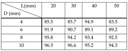 |
Table 5.
Hydrogen target thickness in [µg/cm2], averaged over the gap between the nozzle exit and the catcher tube entrance, for different nozzle lengths (L) and outlet diameters (R). The stagnation pressure P0 = 25 bar and the nozzle temperature T0 = 296 K for all calculation variants. Time after the pulsed valve opening is 100 µs.
 |
Disclaimer/Publisher’s Note: The statements, opinions and data contained in all publications are solely those of the individual author(s) and contributor(s) and not of MDPI and/or the editor(s). MDPI and/or the editor(s) disclaim responsibility for any injury to people or property resulting from any ideas, methods, instructions or products referred to in the content. |
© 2024 by the authors. Licensee MDPI, Basel, Switzerland. This article is an open access article distributed under the terms and conditions of the Creative Commons Attribution (CC BY) license (http://creativecommons.org/licenses/by/4.0/).
Copyright: This open access article is published under a Creative Commons CC BY 4.0 license, which permit the free download, distribution, and reuse, provided that the author and preprint are cited in any reuse.


