Submitted:
30 November 2023
Posted:
01 December 2023
You are already at the latest version
Abstract
The prohibitive costs of small-scale solar photovoltaic (PV) racks decreases PV adoption velocity. To overcome these costs challenges, an open hardware design method is used to develop two novel variable tilt racking designs. These are the first stilt mounted racking designs that allow manual change of tilt angle from zero to 90 degrees by varying the length of cables. The racks are designed using the calculated dead, wind and snow loads for Canada as conservative design for most of the rest of the world. Structural capacities of the wooden members are then ascertained and resisting bending moment, shear force, tensile force, and compressive force for them is calculated. A structural and truss analysis is performed to ensure that racking design with-stands the applicable forces. Moreover, implications of changing the tilt angle on the wooden members/cables used to build the system are also determined. The systems offer significant economic savings ranging from 1/3rd to 2/3rd the capital expenses of the commercially available alternatives. In addition, the racking designs are easy-to-build and require minimal manufacturing operations, which increases their accessibility. The stilt-mounted designs can be employed for agrivoltaic settings while allowing farm workers shaded ergonomic access to perform planting, weeding, and harvesting.
Keywords:
open source
; racking
; biomaterials
; wood
; photovoltaic
; mechanical design
; balance of systems
; renewable energy
; solar energy
1. Introduction
Solar photovoltaic (PV) technology has been established as a means to maintain our energy-intensive standard of living while shifting society to a sustainable state [1]. The primary impediment to this transition has been economic, but PV technology has consistently dropped in price for decades [2,3], to the point that the solar levelized cost of electricity (LCOE) [4] is the lowest-cost option at both the small and large scales [5,6]. Low-cost carbon-free solar electricity has made PV the most rapidly-expanding source of electricity [6,7] and the true dominant new source of power now [8]. Although PV at the large-scale is often the core focus of energy policy [9], to achieve the U.N. ‘Sustainable Energy for All’ goals, small-scale single-family-home PV systems can play a major role [10], as they save consumers money [11]. The economics tilt further in solar’s favor when the entire value of solar is determined [12]. Although in general PV is an economic benefit, the initial capital expenditures (CAPEX) of PV systems present a barrier to consumers in both the developing [13] and developed economies [14].
Although large-scale industrial-based PV costs have been the lowest and dominate the market [9], small-scale, open source do-it-yourself (DIY) or even ‘plug-and-play’ solar [15,16] can have costs that are lower than large scale systems [17]. In general, the larger a system the lower its costs per unit power [18]. This is because a substantial fraction of a PV system’s cost is still soft costs (e.g., regulatory costs) that are the same or similar regardless of scale. Thus, there is a need to change regulation to enable small-scale PV systems to meet their full potential [16,19,20,21] as in aggregate such systems could have a massive environmental and economic benefit [22].
Most of the PV system costs declines have come from the PV modules, while there has been very little progress on the balance of systems (BOS), which includes the racking, electronics, and wiring [3,23,24]. Simple mechanical racking dominate the costs of small PV systems, and proprietary and costly aluminum extrusion profiles have barely reduced costs [25]. To put this into perspective PV module spot prices are currently US$0.125/W [26] so an approximately 1kW system would cost $125 while a 3-module rack costs US$459 [27], which is triple the PV cost and a 3-module pole mount racking systems costs US$1,312 [28], which is nine times the cost of the PV modules.
These prohibitive costs of small-scale racks make it very challenging for small system potential owners to participate in some of the most interesting and fastest growing areas of PV like agrivoltaics [29,30]. Agrivoltaics is the dual use of land for the purpose of agriculture and solar-PV electricity generation [31,32,33,34,35]. The racking structures used for agrivoltaics, such as the stilt-mounted configurations, however, increase the cost of racking structure [36,37], which increases the cost differential per unit power between small and large system owners even further. These racks require more material due to increased height and so there is a critical need to reduce the capital costs.
An effective means to reduce PV racking costs is to use open source hardware for distributed production of racking including: i) low-tilt angle racks for mobile PV arrays [38], ii) cable-based X-wire PV racking systems for both flat commercial rooftops [39], as well as iii) ground-mounted PV systems near the equator [40], iv) tensegrity-based PV racking [41], v) after-market building integrated PV (BIPV) [42], vi) fixed-tilt ground mounted wood racking [43], vii) variable-tilt wood racking [44], viii) vertically-mounted wood racking PV systems [45], ix) fence-based PV systems [46], x) aftermarket floatovoltaics [47], xi) trellis-based agrivoltaics racking [48], and a xii) cable and pipe-based mobile photovoltaic racking [49]. No racking design, however, has focused on agrivoltaics as well as normal PV along with the flexibility of changing tilt angle manually with stilt mounted systems in the literature.
To fill this knowledge gap, this study proposes two novel low-cost, sustainable, easy-to-build, variable tilt racking designs. These are the first stilt mounted racking designs that allow manual change of tilt angle by varying the length of cables. The racks are designed using the calculated dead, wind and snow loads for Canada as a conservative design for most of the rest of the world. Structural capacities of the wooden members are then ascertained and resisting bending moment, shear force, tensile force, and compressive force for them is calculated. A structural and truss analysis is performed to ensure that racking design withstands the applicable forces. Moreover, implications of changing the tilt angle on the wooden members/cables used to build the system is also determined. The results are reviewed and discussed for the novel racking systems applications in agrivoltaics, fencing and parking lots/street parking as they can provide shade to automobiles.
2. Materials and Methods
2.1. Selection of Wood & Wire Rope
The primary construction materials for the racking design is wood due to its widespread availability and sustainability [50]. While growing wood absorbs carbon dioxide, it can be repurposed/recycled after its primary uses or can be utilized as biofuel [51]. In comparison with other racking materials, wood has lower energy requirements for processing which translates into a negative embodied energy and carbon footprint [52]. When compared to a ton of steel, softwood required 24 times less energy for the same mass [52]. Aluminum, a commonly used material for PV racks, has over 5 times the embodied CO2e/kg of wood [53]. Moreover, using wood as a construction material for PV module mounting structure also has distinct economic benefits especially in North America [54]. In addition, to hold as well as provide the option of changing the tilt angle of PV modules, wire rope is being used. Wire has been used before in x-wire based low-tilt angle racking systems [39] and tensegrity racking [41]. Here its primary function will be to vary the tilt angle of the array while enabling flexibility to ensure smaller members are able to be used for a given wind load.
2.2. Dimensional and Mechanical Characteristics of Wooden Members and Cables
Table 1 provides a summary of the dimensional and mechanical properties of the wooden members. It is utmost important that during construction, the base of any member should be smaller than its height. This ensures that the lumber is loaded along its strong axis, leading to an optimal moment of inertia and first moment of area.
2.3. PV Racking Design Parameters
For designing the PV rack, 460 W rated 144 HC M6 Bifacial Module [56] is selected. Using a bifacial PV module increases the electrical output [57,58] as well as assists clearing snow on the front side of the PV module [59,60]. The modules have dimensions of 2108mm x 1048mm. If modules with different measurements are used, the design can be adjusted to meet specific module requirements. The proposed racking design has a height of approximately 1.8m above the ground, ensuring a 500mm ground clearance—sufficient for snow sliding, even in the most extreme northern atmospheres [61]. A case study is presented where the racking structure is specifically designed for London, Ontario, with a latitude and longitude of 42.9849° N and 81.2453° W.
2.4. Main Design
2.4.1. T-Shaped Wood & Cable Design
The racking design consists of two posts, 140mmx140mm in cross section. The height of the posts is 1848mm above the ground with approximately 1200mm under the ground forming the foundation of the rack. One beam, 38mm x 286mm in cross section is attached to the posts to hold one end of the PV module. The other end of the module is held via 3/8” galvanized aircraft cable from the two sides [62]. Changing the length of the wire enables the change in the tilt angle of the modules. The analysis is performed with cables assumed to be making a 15o angle with the horizontal. Two modules are held between the two posts. Figure 1 shows the assembly of the structure with labelling.
2.4.2. Cantilevered Carport Wood & Cable Design
The structure consists of two posts, 184mmx184mm in cross section. As for the T-shaped design, the height of the posts is 1848mm above the ground wit. One beam, 38mm x 140mm in cross section, is attached to the posts to hold one end of the PV module. The other end of the module is held via 3/8” galvanized aircraft cable from the two sides [62]. Changing the length of the wire enables the change in the tilt angle of the modules. The analysis is performed with cables assumed to be making a 15o angle with the horizontal. A single module is cantilevered between two posts. Figure 2 shows the assembly of the structure with labelling.
A variation to this configuration is the two-module cantilevered design where the modules are cantilevered on each side of the center joist. The same 184mm x 184mm posts are used in this design as well, however, the center joist requires more strength. The structural and truss analysis for this design becomes identical to the two module T-shaped design where a 38mm x 284 mm wooden member is used to hold the load acting on both the modules. Refer to Figure 3 for the assembly of the racking structure.
For both the designs, changing the angle of wire rope influences the tension it experiences. The cables are attached to the wooden members through sheep eye hook screws while cable clamps are also used to close out the ends of the cables. Different lengths of cables can be used to change the tilt angle of the solar modules, or a turnbuckle can also be used for the same. The force experienced by the cable when tied at different angles is ascertained for every 5oangle increment. Moreover, changing the tilt angle of modules changes the loading on the structure, and its subsequent impact on wooden member(s) used in each design is also determined.
2.5. Bill of Materials (BOM)
The bill of materials (BOM) of the T-shaped design is shown in Table 3.
Hardware components used to build the cable attachments are shown in Figure 4.
2.6. Load Calculations
The load calculations are detailed in Appendix B.
2.7. PV System Simulations
PV systems simulations for the advantage of different fixed tilt angle adjustments throughout the year have been summarized previously [44].
2.8. Variables
All variables in this article are adopted from the Jamil et al. [48] trellis-based agrivoltaics racking design.
2.9. Finite Element Analysis (FEA)
FEA is performed to ascertain if the racking design will result in stresses exceeding the yield/design stress of the aluminum frame used to hold the PV modules on the mounting structure. FEA was performed utilizing Abaqus/CAE 2022 on a computer equipped with an 8th generation Core i7 CPU and 16GB of RAM. The PV module FEA model similar to [63] is considered, simulating a standard configuration, encompassed a PV aluminum frame, PV laminate (consisting of glass, solar cells, ethylene-vinyl acetate (EVA), and backsheet), and rubber components. The simulation conducted in Abaqus resembles the boundary conditions of three designs discussed in Section 2.4. The FEA analysis took into account the behavior of the rubber within the PV module, incorporating material behaviors consistent with established research [64,65]. In the simulation, it was assumed that the rubber was bonded to the aluminum frame through tie constraints in Abaqus, and similarly, the laminate was attached to the rubber using tie constraints. Addressing the fasteners, one side of the PV module's length had the frame's bottom constrained in the Z direction to represent placement on a wooden rack, while a portion of the bottom on the other side was fixed in the Z direction to simulate the fixture used for the PV module as demonstrated in Figure 5. In another model, the boundary conditions for fixtures on the PV module are removed to see how this affects the final results. In the main FEA model, the bolts under the bottom of PV aluminum frame were simulated following a methodology presented by [63] to model their boundary conditions. Also, to analyze an alternative configuration for mounting PV modules with no fixtures, in another simulation, the bolts were considered to be drilled from the sides of the PV frame as shown in Figure 6. The material properties for all components used in the FEA are outlined in Table 6. The simulations considered the weight of all components, acknowledging its significance in real-world applications.
For meshing, linear hexahedral mesh elements were employed, aligning with prior studies [63,65]. In all simulations, seed and element sizes were reduced as much as possible to constrain computational time based on available computational resources. To enhance the precision of the FEA results, various partitioning methods in Abaqus were utilized, facilitating the application of sweep and structured techniques for meshing all parts more efficiently. These methods were thoughtfully selected to eliminate any flawed or error-associated elements from the simulations, thereby bolstering the reliability of the findings. The collective considerations outlined above were implemented to ensure that the FEA results would closely align with real-world conditions and provide accurate insights.
3. Results
3.1. Loads
3.1.1. Snow Loads
The snow load for London, ON, comes out to be 1.771 kPa following equation (B1-1) up to a tilt of 15o. The snow load changes when the tilt of the modules changes. For 30o tilt, it is 1.334 kPa, for 45o, it is 0.897 kPa and for 60o, it is 0.460 kPa.
3.1.2. Wind Loads
Using equations (B2-1, B2-2, and B2-3), the external pressure, the internal pressure and the total wind load are found out to be -0.98 kPa, -0.68 kPa and -1.66 kPa respectively.
3.1.3. Dead Load
The CanmetENERGY research center at Natural Resources Canada [66] advises that the dead load of PV systems, commonly known as the superimposed dead load, should be accounted for as 0.24 kPa. For the weight of lumber, it is advisable to utilize the wooden member weight supplied by the supplier and transform it into a uniformly distributed load measured in kN/m.
3.1.4. Load Combination
The load combinations that yield the highest and positive and negative values are given in Table 7.
Given that all connections are capable of handling loads in both directions, and all members exhibit similar material properties in both directions, the analysis for the negative case is essentially identical to the positive case. Consequently, there is no requirement to specifically evaluate both the cases, and the analysis will only be performed for the case which carries a higher load value.
3.2. Wooden Members Structural Capacity
In Canada, spruce pine fir grades 1 and 2 make up most of the pressure treated wood used for construction and its mechanical properties [67] are given in Table 8.
Resistance factors are provided in Table 9.
Following equations (B5-1, B5-2, B5-2, B5-4, B5-5, and B5-6), the factored properties of pressure treated spruce pine fir wood are given in Table 10. The table only shows the values for the most conservative case where the solar modules are placed horizontally.
The resistance values are next determined using the factored capacities calculated above as well as the dimensional properties of the lumber (Equations B5-7, B5-8, B5-9 and B5-`0). Table 11 summarizes the resisting values for differently sized wooden members when the solar modules are held horizontally on the structure.
Subsequently, structural analysis is performed to ascertain optimal dimensions of wooden member required for construction of a functional system.
3.3. Structural Analysis
3.3.1. Joist
The joist connected with the two posts have a tributary width of 1.064m for two module T-shaped designs and 1.054m for cantilever design.
Total uniformly distributed for the joist comes out to be 3.96kN/m and 3.93 kN/m for the two designs using equation (B6-1).
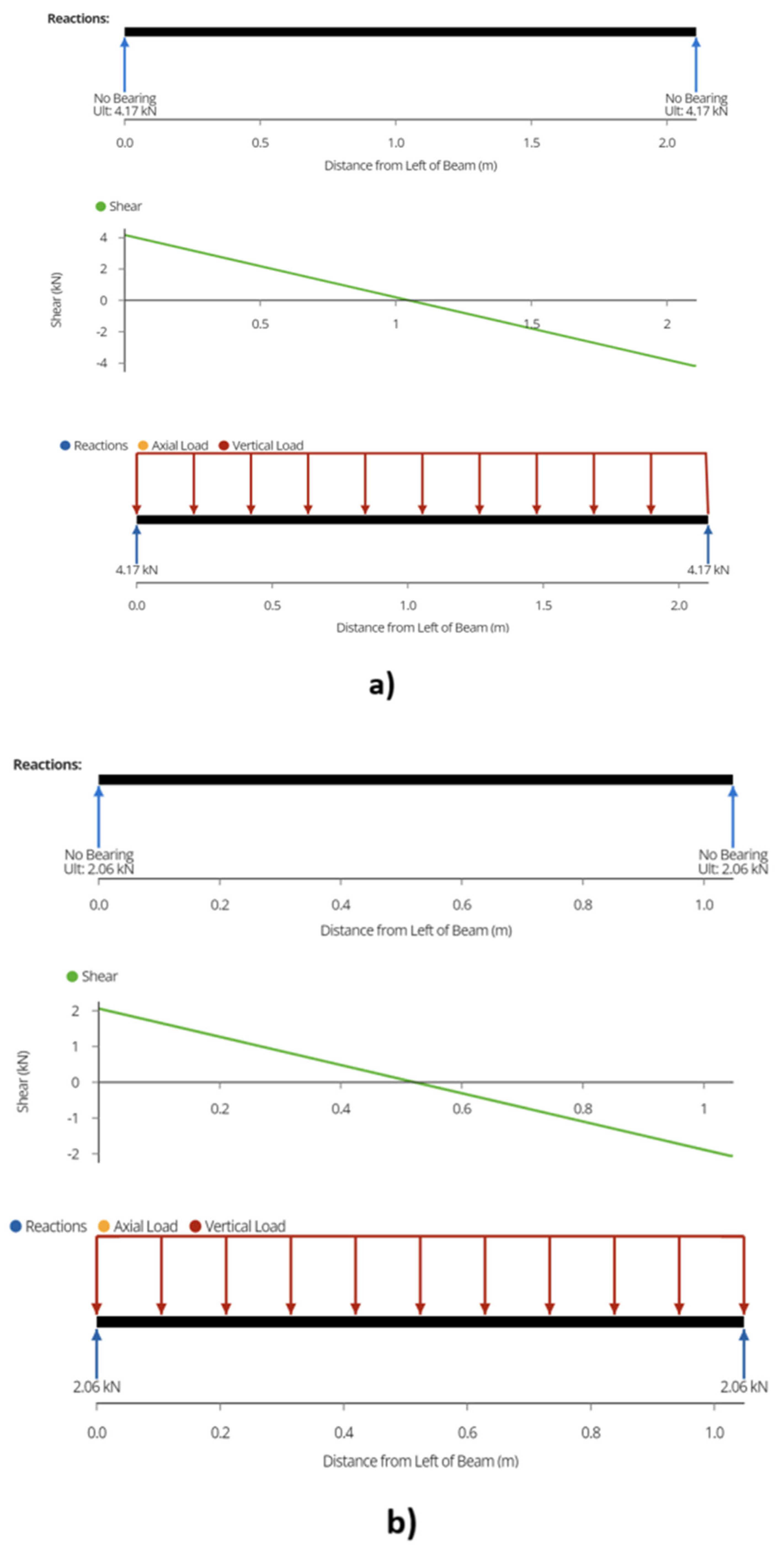
Following equation (B6-2), the maximum shear force or reaction is found out to be 4.18 kN for T-shaped variable tilt racking system and 2.05 kN for cantilever design (Figure 6).
Figure 6.
Reaction and Maximum Shear Forces a) T-shaped and cantilever two module design, b) Cantilever one module design.
Figure 6.
Reaction and Maximum Shear Forces a) T-shaped and cantilever two module design, b) Cantilever one module design.
Moreover, the bending moment is determined as 2.20 kN-m and 0.54 kN-m for the two structures from equation (B6-3) as depicted in Figure 7.
Finally, the maximum deflection using equation (B6-4) is ascertained as 1.42 mm and 0.086 mm for the two designs (Figure 8).
The structural analysis is performed for 30o, 45o and 60o tilts of solar modules as well using the respective snow loads. For the two module T-shaped variable tilt racking design, the maximum shear or reaction is reduced to 3.44 kN, 2.96 kN and 2.72 kN for the three angles on the center joist. The bending moment comes out to be 1.81 kN-m, 1.56 kN-m, and 1.43 kN-m whereas the deflection is calculated as 1.17mm, 1.01mm and 0.93mm respectively. This means that with 45o and 60o tilts, 2x10 pressure treated wood can be used.
For the cantilever variable tilt racking configuration, the maximum shear or reaction force on the middle joist alleviates to 1.70 kN, 1.35 kN and 1.25 kN respectively. The bending moment is calculated as 0.44 kN-m, 0.36 kN-m, and 0.33 kN-m while the deflection comes out to be 0.07 mm, 0.06 mm, and 0.05 mm for the three angles. This subsequently allows using 2x4 wooden lumber for 60o tilt design. For the remaining load scenarios, a 2x6” wooden member shall be used.
3.3.2. Wire Rope
To determine the load on the wire rope, consider a tributary width of 0.534m to determine uniformly distributed load (UDL) which comes out to be 2.03 kN/m using equation (B6-1). For the cantilever design, a tributary width of 1.054 m is considered and UDL is found out to be 3.93 kN. The maximum shear or reaction comes out to be 2.14 kN and 2.05 kN at the ends following equation (B6-2) shown in Figure 9.
To determine the load on the wire rope, a truss analysis is performed detailed in Appendix C. The force on the wire cables connecting the modules from the top is considered only. This is to make the analysis conservative, where the snow, wind, and dead load act from the top. So, if the wires at the top survive, the bottom wires will perform satisfactorily as well. 2.15 kN force will be acting on each wire rope vertically downward as shown in Figure 6. The maximum tension in the wire rope comes out to be 8.30 kN. Similarly, for cantilever design, a 2.06 kN force acts on the cable vertically downward which results in a maximum tension of 7.95 kN. The load is next transferred to the post.
Changing the angle of the wire cable reduces the force it experiences while holding the modules. For horizontal modules, changing the angle from 75o to 15o varies the force in the cable from 8.30 kN to 2.22 kN, respectively. A suitable cable can then be selected based on the system design and parameters. Similar to the two-module design, an iterative analysis for wire rope is performed for different angles. The calculations suggest that the cable experiences 7.95 kN force when installed at a 75o angle which reduces to 2.13 kN when the angle reduces to 15o. Figure 10 represents a graphical account of the analysis.
3.3.3. Posts
The allowable force for a 6x6 column 1848mm in height comes out to be 223.43 kN, while for an 8x8 column, it is calculated as 666.66kN (Eq B6-5). From the truss analysis (details in Appendix C), the load acting on the posts is determined to be 8.16 kN (Figure 11 and Figure 12).
Regarding the ground, if the applied pressure surpasses the permissible limit, there are two potential courses of action. Firstly, 150 mm of compacted clear stone gravel can be added to the base of the footing. Alternatively, the diameter of the footing can be increased.
Figure 13 shows the FEA results of the PV module under the proposed configuration and load combination of wind, snow, and dead load (3620 Pa). According to the FEA, the maximum stress on PV module (129.80 MPa placed on the middle of frame’s width) is lower than strength of aluminum proving the mechanical stability of PV module under this configuration. Furthermore, using this type of installation and load for PV modules will lead to the maximum displacement of 20.99 mm in the middle of PV module’s laminate. Comparing these values with similar study in the literature [63] reveals that PV modules under the IEC 2400 Pa load exhibit the maximum stress from 78 MPa to 138 MPa and the maximum deflection from 9.2 mm up to 18.6 mm. Considering the fact that in this study, the net load of 3620 Pa is considered, results are in line with the literature results. Excluding the fixture from the bottom of the PV module can increase the stress and deflection of PV module significantly leading to failure under the 3620 Pa load as shown in Figure 14. Therefore, using the fixture is crucial as a support provider for the bottom of frame preventing the maximum stress on PV module to exceeds the strength limit. Similarly, FEA results for side bolts model presented in Figure 15 demonstrate instability in this configuration leading to exceeding the strength limit of aluminum considerably. Using this design in the real world in the presence of extreme weather conditions can lead to the failure of PV modules. Hence, modifications are needed for this design to make it mechanically stable, such as adding a fixture under the bottom of PV module as a support similar to what presented in main design.
The racking design is competitive when compared to other racking designs as shown in Table 12.
4. Discussion
4.1. Wooden Racking Economics
Levelized cost of electricity (LCOE) is an excellent measure to show the influence of transitioning from a fixed tilt racking design to a variable tilt racking configuration on energy production. Although the initial investment for a fixed tilt system may be lower, previous study has indicated that the LCOE values for both the systems (fixed and variable tilt) come out to be similar (~CAD$ 0.01/kWh) [44]. This aspect plays a crucial role for the user/customer in determining which racking designed to be installed at a location. The designs presented in this study are suitable for installations at various locations and applications including carports, agricultural lands, etc.
These variable tilt racking structures using metal cables are cost effective when compared to the ones commercially available. The racking systems presented in this study also present similar functionality as those available in the market. Also, the racking design will require minimal labor to be set up and installed. The system does not require any cutting as the wooden members of the sizes mentioned in the BOM can be used. There are only two joists to column connections while the remaining connections are made through cable clamps and eye hooks. The cost of typical ground mount commercial racking designs vary from USD$0.68/W (CAD$0.92/W) to USD$1.15/W (CAD$1.55/W) for a 1-kW solar PV system [68]. Previously presented wood racking designs cost around CAD$0.13/W to CAD$0.50/W. These structures are generally fixed tilt; the only variable tilt design in the literature is a low height conventional racking system. The configurations presented here provide a stilt mounted variable tilt racking, particularly useful to be used in carports and in any type of agrivoltaics systems where equipment or livestock needs to traverse underneath the modules. The carport racking designs commercially available range from CAD$ 1.30 to 1.50 per W [69]. According to EnergySage, the average cost of a complete solar carport is USD$3.31/W which is approx. 18% more expensive than a normal rooftop installation [70]. Sunwatts offers carport racking designs (upto 16kW rating) at a price of USD$1.56/W [71]. According to NREL report in 2021, the racking cost for a residential PV system is USD$0.08/W, commercial PV system is USD$0.11-0.17/W while for a large scale solar farm is USD$0.12/W [72]. The racking configuration discussed in this article can also be employed on pathways or walkway awnings. The integration would certainly be beneficial as an energy generation source but also, it might give an aesthetic appeal to the structure while at the same time provide shelter. Using semi-transparent PVs that allow diffused sunlight to pass through may further create a visually captivating ambiance with novel racking structure.
For proof-of-concept, an agrivoltaic system was built with spectral-shifting semi-transparent PV modules as shown in Figure 16. Turnbuckles and hooks are used at one end of the cable (where it attaches with 6x6 column) while eyebolts are used at the other end. An angle iron is attached to the solar modules to connect the eyebolts. Two light duty T-hinges (Figure 17) are used for changing the tilt of the module as the turnbuckle is loosened/tightened. Else, different lengths of cables can also be used to change the tilt angle of the solar modules.
4.2. Agrivoltaics
There is a growing concern among rural residents about large scale PV developments, similar to what's been observed in conflicts over wind power siting [73,74]. The resistance to large-scale PV deployment mainly arises from worries about reduced agricultural productivity and subsequent employment impacts and potential food insecurity/raises in food costs [75,76,77,78,79]. Thankfully, this conflict can be resolved by employing a dual land use approach, allowing land to be utilized for both solar PV electricity generation and farming, a concept known as agrivoltaics [32,33,34,35,80].
Agrivoltaics offer a wide range of benefits, including renewable electricity generation, reduced greenhouse gas emissions, enhanced crop yields, protection of plants from excessive solar energy and inclement weather conditions such as hail etc., water conservation, agricultural employment, local food production, and increased revenue [31]. The variable tilt stilt mounted racking systems analyzed in this study holds particular value for agrivoltaics. The designs offer a very cost-effective solution tailored for agrivoltaic farms. The modules are elevated to allow ease of agricultural operations including harvesting, planting, or weeding. Crops including cucumbers, grapes, kiwi, melons, peas, passion fruit, pole beans, pumpkins, strawberries, squash, tomatoes etc. are well suited for this racking configuration [48]. The tilt angle for solar modules can also be altered for plant protection. The adjustment of tilt angle requires minimal labor by using turnbuckles, or different length of cables. The combination of farming and PV electricity generation provides a dual revenue stream for farmers increasing profits per acre. Deployment of agrivoltaics can also enhance the stability of rural electric grids. Finally, if agrivoltaic systems incorporate storage, they can create emergency islanded power grids to reduce outage impacts, a valuable feature for isolated communities [81,82]. The market for agrivoltaics is expected to increase exponentially in the coming years. It is projected to expand from USD$ 4.1 billion in 2023 to USD $8.9 billion in 2030 [29]. It already surpassed USD $3.5 billion in 2022 [29].
4.3. Wood Price Sensitivity
The system's cost is significantly influenced by fluctuations in lumber prices. Record volatility was observed in wood prices in 2021 [83]. The contract lumber’s commodity price index chart, depicting the average rough framing lumber package, is a tool that assists keeping track of the percentage increase/decrease in price over time [83]. In 2020, the price index was 70% higher than 2019, while the first six months of 2021 showed 108% increase [83]. When compared to 2015, the price of wood increased more than two-folds as of 2021 [84]. Price voltatility in wood products is mainly driven from conservatism, lack of infrastructure and emotional trading [85]. The expenses associated with this design will also depend on the accessibility of the local wood market and, if imported, the applicable taxes and import duties. Table 13 provides information about the standard prices of construction-grade pressure-treated 2x4x8 lumber in different countries. A previous study have revealed that wood-based racks were more cost-effective in North America and certain South American nations, whereas metal proved to be a more economical choice in Central and South America [54].
This is the first open-source wood-based photovoltaic racking that allows variation in the tilt angle for a stilt mounted structure. The designs offer several distinct attributes. First, it is constructed from sustainable, locally available materials, thus promoting environmental responsibility. Second, the design process is simple requiring very few fabrication/construction steps. It can therefore be easily manufactured using basic hand tools, making it accessible to an average user. Moreover, it aligns with the industry standard PV warranty by providing a 25-year lifespan. The racking configuration is robust and resilient as it can withstand high wind speeds and significant snow loads, adapting to specific regional conditions. Furthermore, it offers cost-effectiveness, making it an economical choice. Lastly, it operates under an open-source license, facilitating widespread access for self-fabrication and allowing companies to create customized versions for local markets.
4.4. Permits and Certification
Although roof mounted PV systems require professional engineering stamps and building permits to install, these ground mounted systems do not require these. Racking only requires a professional engineer’s stamped approval if the racking is not CSA approved [86]. In the case of this system, all wood used is marked and graded as SPF No.2 grade, which indicates CSA’s approval for structural use. The design complies with National Research Council’s National Building Code of Canada, which works together with CSA, and the National Design Specification for Wood Construction, which follows CSA O86:19 Engineering design in wood.
Most municipalities, such as the City of Toronto, do not require building permits for ground mounted PV systems of any size, and thus plans and calculations do not need to be stamped and signed by a registered engineer [87]. Some municipalities, such as the City of Waterloo, specify that building permits are not required such that the system is not connected to water or heating resources [88]. Very few municipalities, such as the city of London, only require a work permit if excavation is required, or if scaffolding and cranes are used [89]. In all cases, these ground mounted systems are an exceptional alternative to roof-mounted systems because they avoid a lot of the red-tape associated involved with tying to an existing structure. This allows costs to remain low, construction to be completed quickly, and for PV systems to remain a feasible option as a DIY alternative.
4.5. Future Work
The racking designs presented in the paper have the potential for further research and innovation. Although the system integrates clean energy generation with sustainable construction material (wood), an investigation into advanced sustainable composite materials needs to be undertaken which are more resilient, weather resistant and provide a longer lifespan. More efficient and cost-effective designs for PV racking need to be further explored. This can be done by optimizing manufacturing processes, reducing installation costs, and increasing market awareness. Structural design optimization is key in order to further integrate PV technology in the communities. Furthermore, a comprehensive life cycle analysis (LCA) assessing the environmental impacts of wood-based PV racking systems should also be performed. An overall evaluation of carbon footprint, energy requirements etc. of these designs compared to others can be made part of such a study. Research focusing on understanding the maintenance and durability of these racking designs should also be carried out. This may include a monitoring system for detection of issues and periodic replacement of deteriorated wooden members. Another important aspect to be looked at includes the development of guidelines, procedures and standards for responsible sourcing of wood which is utilized in the renewable energy industry. Moreover, innovative techniques to preserve wood may also be explored which can improve decay resistance properties of wood.
5. Conclusions
This study outlined two novel open-source wood and cable-based PV racking systems with adjustable tilt angles that exceed Canadian building code standards and are thus applicable to the vast majority of the world’s populations. The tilt angle can vary from 0o (horizontal) to 90o (vertical), thus, offering a distinct feature and flexibility not explored in the previous literature. The systems offer significant economic savings and incur approximately one-third to less than two-thirds the capital expenses of the commercially available variable tilt racking solutions. In addition, the racking designs are easy-to-build and require minimal manufacturing operations. These features indicate that they would be widely accessible throughout the world. The economic analysis indicates that, in various scenarios, the new variable tilt rack offers the most cost-effective option, but these results are heavily material, labor and location dependent. Ultimately, the innovative design of the variable tilt racking system presented here has several distinct advantages over fixed tilt designs, especially in applications like agrivoltaics. The stilt-mounted designs can be employed for agrivoltaic settings since the the solar modules are installed at increased height than conventional PV racking structures and thus allow farm workers shaded ergonomic access to perform planting, weeding, and harvesting operations.
Author Contributions
Conceptualization, J.M.P.; methodology, U.J. and N.V.; software, U.J., S.A.S. and N.V.; validation, U.J., S.A.S. and N.V.; formal analysis, U.J., N.V., S.A.S. and J.M.P.; investigation, U.J. , S.A.S. and N.V.; resources, J.M.P.; data curation, U.J. and N.V.; writing—original draft preparation U.J., N.V. and J.M.P.; writing—review and editing, U.J., N.V., S.A.S. and J.M.P.; visualization, U.J., S.A.S. and N.V.; supervision, J.M.P.; funding acquisition, J.M.P.
Funding
This research was funded by Thompson Endowment and the Natural Sciences and Engineering Research Council of Canada (NSERC).
Data Availability Statement
Data will be made available upon request.
Conflicts of Interest
The authors declare no conflict of interest. The funders had no role in the design of the study; in the collection, analyses, or interpretation of data; in the writing of the manuscript, or in the decision to publish the results.
Appendix A. Design Analysis Assumptions
Here, several assumptions have been made to streamline the calculations, and they have been deliberately kept conservative to ensure structural integrity under the most extreme field conditions. To elaborate:
All applied loads are considered to act perpendicular to the module face, ensuring that the middle joist undergoes the maximum flexural load.
All members are connected with pins and have no fixed end moments. This assumption takes into account that joist hangers and brackets allow for rotation [90].
Following NBCC 4.1.6, the wind load and snow load are assumed to be evenly distributed across the module surface, as considerations for snow and wind accumulation apply primarily to large structures [91].
The Heliene 144HC M6 module is specified to withstand a front load of up to 5400 Pa and a rear load of up to 2400 Pa [56]. Given that the design loads will be significantly lower than these values, the modules exhibit ample structural capacity.
Appendix B. Load Calculations
B1. Snow Loads
The specified snow load is determined as per National Building Code of Canada (NBCC) [91]:
S = Is[Ss(CbCwCsCa)+Sr] [kPa]
The importance factor for snow load (IS) is considered as 1.15 since the failure of PV racking structure poses a risk to the life of people working underneath the structure. This is a conservative estimate as a factor of 1.00 could be used since the risk of people being under the racks in inclement weather such as high winds and storms is very low.
The 1-in-50-year ground snow load factor (SS) is dependent on the location where the racking structure is being built. Using Table C-2 in NBCC for London, ON, a value of 1.90 is determined.
The basic roof snow load factor (Cb) is considered 0.80 if lc is less than or equal to the factor (70/Cw2). Here Cw is the wind exposure factor and lc is the characteristic length of the upper or lower roof. The value of lc is evaluated using the equation 2w - w2/l where w is the smaller plan dimension of the roof and l is the larger plan dimension of the roof. For the design, lc is found out to be less than (70/Cw2).
The wind exposure factor (Cw) is considered as 0.75 since our racking design will be exposed to wind in all directions.
The slope factor (Cs) is dependent on the tilt angle of the system. Assuming the slope is less than 15o, Cs is taken as 1.
For calculations, the accumulation factor (Ca) is considered 1.00 for small single slope structures.
The 1-in-50-year associated rain load (Sr) is dependent on the location where the racking structure is built. Following Table C-2 of NBCC for London, ON, a value of 0.4 is ascertained.
Table 14 summarizes the factors used for calculating snow load:

Table 14.
Snow Load Factors.
| Factor | Value |
|---|---|
| Importance Factor (Is) | 1.15 |
| Snow Load Factor (Ss) | 1.90 |
| Basic Roof Snow Load Factor (Cb) | 0.80 |
| Wind Exposure Factor (Cw) | 0.75 |
| Slope Factor (Cs) | 1.00, 0.67, 0.33 and 0 |
| Accumulation Factor (Ca) | 1.00 |
| Associated Rain Load (Sr) | 0.40 |
B2. Wind Load
Using National Building Code of Canada (NBCC) 2020, the wind load is determinedwhich is a summation of both external wind pressure as well as internal wind pressure.
W = p + pi [kPa]
W is the total wind load in kPa
p is the specified external wind pressure in kPa
pi is the specified internal wind pressure in kPa.
The following equations govern the external and internal wind pressures:
p = IwqCeCtCpCg [kPa]
pi = IwqCeiCtCgiCpi [kPa]
The wind importance factor (Iw) considered as 1.15 as the failure of PV rack may risk the life of people working underneath the structure.
The reference velocity pressure (q) is dependent on the location where the racking structure is constructed. Follwoing Table C-2 in NBCC for London, ON, a value of 0.47 is ascertained.
The exposure factor (Ce) is calculated using the expression (h/10)0.2. Here, h is considered 6m as the height of the structure is less than 20m while it is also less than the smaller plan dimension. The value of Ce is determined to be 0.90.
The topographic factor (Ct) is considered as 1.00.
The external pressure coefficient (Cp) and gust effect factor (Cg) are combined. Using Table 4.1.7.6, the value of the product is found to be -1.30.
The exposure factor for internal pressure (Cei) is the same as the exposure factor ‘Ce’ since wind can attack the inside of the system in the same way as the outside.
The internal gust effect factor (Cgi) is taken as 2.00.
The internal pressure coefficient (Cpi) is taken as -0.70.
Table 15 summarizes the factors used for calculating snow load:
Table 15.
Wind load Factors.
| Factor | Value |
| Wind Importance Factor (Iw) | 1.15 |
| Reference Velocity Pressure (q) | 0.47 |
| Exposure Factor (Ce) | 0.90 |
| Topographic Factor (Ct) | 1.00 |
| External Pressure Coefficient and Gust Effect Factor ‘Cp.Cg’ | -2.00 |
| Exposure Factor for Internal Pressure (Cei) | 0.90 |
| Internal Gust Effect Factor (Cgi) | 2.00 |
| Internal Pressure Coefficient (Cpi) | -0.70 |
B3. Dead Load
The structure's dead load ‘D’ takes into account the PV module weight and the wooden member weights and represents the weight of the structure itself. The weight of brackets and fasteners is insignificant compared to the design load and can be considered negligible.
B4. Load Combinations
To address the simplified assumptions made during the design, it becomes imperative to include safety factors to the specified loads, aiming to minimize the probability of failure. These adjusted loads (factored loads) are combined as principal loads and companion loads, adhering to the load combinations outlined in Section 4.1.3.2 of NBCC. The calculations must carefully consider the combination of principal loads and companion loads that yields the highest net load. Principal loads constitute the essential loads requiring evaluation, while companion loads are incorporated only if they act in the same direction as the principal loads. It is crucial to highlight that the design wind load operates in the negative direction, whereas the governing snow load is in the positive direction. Consequently, combining these loads would reduce the net load and is therefore not recommended.
B5. Wooden Members Structural Capacity
The National Design Specification for Wood Construction [67] provides reliable design values for a variety of wood types.
Although these capacities have shown reliability, it is extremely important to incorporate resistance factors into these capacities to accommodate unforeseen vulnerabilities and ensure an optimum, safe, and functional design.
The load duration factor (CD) is taken as 1.15 considering typical design load, i.e., the governing load, as snow load.
The temperature factor (CT) is considered 1.00 since the racking structure is not expected to be exposed to a temperature of above 100oF.
The wet service factor (CM) is found out to be 1.00 for calculating factor fb, fc, and ft, 0.97 for factored fv and 0.90 for factored E and Emin
The beam stability factor (CL) is calculated as 0.64, 0.76, 0.97 and 0.98 according to the guidelines in Section 3.3.3. of National Design Specification [67].
The flat use factor (Cfu) is considered as 1.20 and 1.15 as per Table 4B of NDS Supplement [67].
The incising factor (Ci) is ascertained from table 4.3.8 of NDS and comes out to be 0.8 except for when determining factored E and Emin where its value is considered 0.95 and for fc where its value is considered as 1 [67].
The repetitive member factor (Cr) is taken as 1.00.
The size factor (CF) is 1.10 as per table 4A of NDS Supplement.
The compression factor (CP) (calculated using the dimensions of the posts) is calculated in accordance with Section 3.7.1. of NDS and comes out to be 0.29 for 6x6 members.
The National Design Specifications for Wood Construction provide the formulae for calculating the factored properties. The formulae are given below:
Factored bending stress = fb* = fbCDCMCtCLCFCfuCiCr [MPa]
Factored shear stress = fv*=fvCDCMCtCi [MPa]
Factored tensile stress = ft*=ftCDCMCtCFCi [MPa]
Factored compressive stress = fc*=fcCDCMCtCFCiCP [MPa]
Factored Elastic modulus = E*=ECMCtCi [MPa]
Factored Emin = Emin*=EminCMCtCiCT [MPa]
Using the factored capacities calculated equations described above and the dimensional properties of the wooden members, the resistance values arere finally ascertained. Theformulae are given below:
Resisting bending moment = Mr =(2fb*I/h) [kN-m]
Resisting shear force = Vr =(fv*Ib/Q) [kN]
Resisting tensile force = Tr =ft*A [kN]
Resisting compressive force = Cr =fc*A [kN]
To ensure the structural integrity of each member and circumvent system failure, the following conditions must be satisfied:
The resisting bending moment (Mr) must equal or exceed the maximum applied bending moment (Mmax).
The resisting shear force (Vr) must equal or exceed the maximum applied shear force (Vmax).
The resisting tensile force (Tr) must equal or exceed the maximum applied tensile force (Tmax).
The resisting compressive force (Cr) must equal or exceed the maximum applied compressive force (Cmax).
Additionally, the maximum deflection (Dmax) should not surpass the member length divided by 360, adhering to NBCC 9.4.3.
B6. Structural Analysis For T-shaped Racking
The net load is evenly distributed across the module’s dimensions. As specified by modules’ supplier Heliene, the panels exhibit sufficient capacity to withstand these loads. Subsequently, the load is transferred from the panels to the joist and then the wire rope. The joist bears its own weight in the form of a uniformly distributed load, designated as 'w'.
w= 1.25 (OW) [kN]
OW is the own weight of the member. The load is multiplied by a factor of 1.25 since it is a dead load [92]. Moreover, to ascertain the uniformly distributed design load, the design load is multiplied with the tributary width for the joist under consideration. Total uniformly distributed load (UDL) is the sum of the own weight and design load.
The wood and cable design only uses one joist. A wooden plank with dimensions of 2x12x8’ is considered for T-shaped variable tilt racking design and 2x6x8’ is considered for cantilever racking configuration while 6x6 column is used for the posts for each design. In case the applied values of bending moment, shear, compression, tension, and deflection exceed the resistance values, a larger member should be evaluated.
The following formula is used to calculate the maximum shear force or the reaction for the middle joist:
Maximum shear or reaction = Total UDL.L/2 [kN]
where L is the length of the joist.
The maximum bending moment is ascertain using the following equation:
Maximum moment = Total UDL.L2/8 ----- [kN-m]
The maximum deflection in the member is ascertained from the following formula:
Maximum deflection = 5.Total UDL.L4/384EI ----- [mm]
Analysis for the joist and wire rope is also performed using Clearcals.
Subsequently, the buckling check for the posts is performed using the Euler Buckling equation given below:
Cbuckling = π2EIweak/(Lk)2 [MPa]
Where the effective length factor, k, is considered 2 for a column fixed at one and free on the opposite end. Next, wire rope and the column are considered to be a truss structure and a truss analysis is performed to determine the forces. The reaction forces from the joist and solar module are considered as the applied forces acting on the truss.
Appendix C. Truss Analysis
C1. Calculations For 2-panel T-shaped Design:
Point A
Using summation of forces as 0 across point A; the forces acting along the member FAB and FAB is determined.
ΣFy=0
-2.14 + FABcos(75) = 0
FAB = 8.30 kN
-2.14 + FABcos(75) = 0
FAB = 8.30 kN
Point B
ΣFy=0
2FABcos(75) + 4.18 = FCOL
FCOL = 8.48 kN
2FABcos(75) + 4.18 = FCOL
FCOL = 8.48 kN
C2. Calculations For Cantilever Carport Design:
Point A
Using summation of forces as 0 across point A; the forces acting along the member FAB and FAB is determined.
ΣFy=0
-2.06 + FABcos(75) = 0
FAB = 7.95 kN
-2.06 + FABcos(75) = 0
FAB = 7.95 kN
Point B
ΣFy=0
2FABcos(75) + 2.06 = FCOL
FCOL = 6.18 kN
2FABcos(75) + 2.06 = FCOL
FCOL = 6.18 kN
References
- Pearce, J.M. Photovoltaics — a path to sustainable futures. Futures 2002, 34, 663–674.
- Fu, R.; Feldman, D.J.; Margolis, R.M. US Solar Photovoltaic System Cost Benchmark: Q1 2018 2018.
- Matasci, S. Solar Panel Cost: Avg. Solar Panel Prices by State in 2019: EnergySage. Solar News, EnergySage 2019.
- Branker, K.; Pathak, M.J.M.; Pearce, J.M. A Review of Solar Photovoltaic Levelized Cost of Electricity. Renewable and Sustainable Energy Reviews 2011, 15, 4470–4482.
- Dudley, D. Renewable Energy Will Be Consistently Cheaper Than Fossil Fuels By 2020; Forbes, 2019.
- Solar Industry Research Data Available Online.
- Vaughan, A. Time to Shine: Solar Power Is Fastest-Growing Source of New Energy. The Guardian 2017.
- Barbose, G.L.; Darghouth, N.R.; LaCommare, K.H.; Millstein, D.; Rand, J. Tracking the Sun: Installed Price Trends for Distributed Photovoltaic Systems in the United States-2018 Edition 2018.
- IEA Solar PV – Renewables 2020 – Analysis Available online: https://www.iea.org/reports/renewables-2020/solar-pv (accessed on 18 October 2023).
- Levin, T.; Thomas, V.M. Can Developing Countries Leapfrog the Centralized Electrification Paradigm? Energy for Sustainable Development 2016, 31, 97–107.
- Lang, T.; Ammann, D.; Girod, B. Profitability in Absence of Subsidies: A Techno-Economic Analysis of Rooftop Photovoltaic Self-Consumption in Residential and Commercial Buildings. Renewable Energy 2016, 87, 77–87.
- Hayibo, K.S.; Pearce, J.M. A Review of the Value of Solar Methodology with a Case Study of the U.S. VOS. Renewable and Sustainable Energy Reviews 2021, 137, 110599. [CrossRef]
- Agenbroad, J.; Carlin, K.; Ernst, K.; Doig, S. Minigrids in the Money: Six Ways to Reduce Minigrid Costs by 60% for Rural Electrification. Rocky Mountain Institute 2018.
- Alafita, T.; Pearce, J.M. Securitization of Residential Solar Photovoltaic Assets: Costs, Risks and Uncertainty. Energy Policy 2014, 67, 488–498.
- International, R. Photovoltaics After Grid Parity Plug-and-Play PV: The Controversy 2013. Renewables 2013.
- Mundada, A.S.; Nilsiam, Y.; Pearce, J.M. A Review of Technical Requirements for Plug-and-Play Solar Photovoltaic Microinverter Systems in the United States. Solar Energy 2016, 135, 455–470.
- Grafman, L.; Pearce, J.M. To Catch the Sun; Humboldt State University Press: Arcata, CA, USA, 2021; ISBN 978-1-947112-62-9.
- Barbose, G.; Darghouth, N.; Millstein, D.; Cates, S.; DiSanti, N.; Widiss, R. Tracking the Sun IX: The Installed Price of Residential and Non-Residential Photovoltaic Systems in the United States. 2016.
- Khan, M.T.A.; Norris, G.; Chattopadhyay, R.; Husain, I.; Bhattacharya, S. Autoinspection and Permitting With a PV Utility Interface (PUI) for Residential Plug-and-Play Solar Photovoltaic Unit. IEEE Transactions on Industry Applications 2017, 53, 1337–1346.
- Khan, M.T.A.; Husain, I.; Lubkeman, D. Power Electronic Components and System Installation for Plug-and-Play Residential Solar PV. In Proceedings of the Proceedings of the 2014 IEEE Energy Conversion Congress and Exposition (ECCE; 2014; pp. 3272–3278.
- Lundstrom, B.R. Plug and Play Solar Power: Simplifying the Integration of Solar Energy in Hybrid Applications; Cooperative Research and Development Final Report. CRADA Number CRD-13-523.
- Mundada, A.S.; Prehoda, E.W.; Pearce, J.M. U.S. market for solar photovoltaic plug-and-play systems. Renewable Energy 2017, 103, 255–264.
- Fthenakis, V.; Alsema, E. Photovoltaics Energy Payback Times, Greenhouse Gas Emissions and External Costs: 2004–Early 2005 Status. Progress in Photovoltaics: Research and Applications 2006, 14, 275–280.
- Feldman, D.; Barbose, G.; Margolis, R.; Bolinger, M.; Chung, D.; Fu, R.; Seel, J.; Davidson, C.; Darghouth, N.; Wiser, R. Photovoltaic System Pricing Trends: Historical, Recent, and Near-Term Projections 2015 Edition 2015.
- Feldman, D.; Barbose, G.; Margolis, R.; Wiser, R.; Darghout, N.; Goodrich, A. Photovoltaic (PV) Pricing Trends: Historical, Recent, and Near-Term Projections, Sunshot 2012.
- PVinsights PVinsights Available online: http://pvinsights.com/.
- Tamarack Solar Products Tamarack Solar Top of Pole Mounts Available online: https://www.altestore.com/store/solar-panel-mounts/top-of-pole-mounts-for-solar-panels/tamarack-solar-top-of-pole-mounts-6072-cell-solar-panels-p40745/ (accessed on 29 June 2023).
- TPM3 Pole Mount for Three 60/72 Cell Solar Modules Available Online.
- Precedence Research Agrivoltaics Market Is Expected to Increase at a 12.15% of CAGR by 2030 Available online: https://www.precedenceresearch.com/press-release/agrivoltaics-market (accessed on 23 August 2023).
- International Energy Agency Solar Available online: https://www.iea.org/energy-system/renewables/solar-pv (accessed on 23 August 2023).
- Pearce, J.M. Agrivoltaics in Ontario Canada: Promise and Policy. Sustainability 2022, 14, 3037. [CrossRef]
- Dupraz, C.; Marrou, H.; Talbot, G.; Dufour, L.; Nogier, A.; Ferard, Y. Combining Solar Photovoltaic Panels and Food Crops for Optimising Land Use: Towards New Agrivoltaic Schemes. Renew. Energy 2011, 36, 2725–2732. [CrossRef]
- Guerin, T.F. Impacts and Opportunities from Large-Scale Solar Photovoltaic (PV) Electricity Generation on Agricultural Production. Environmental Quality Management 2019, 28, 7–14. [CrossRef]
- Valle, B.; Simonneau, T.; Sourd, F.; Pechier, P.; Hamard, P.; Frisson, T.; Ryckewaert, M.; Christophe, A. Increasing the Total Productivity of a Land by Combining Mobile Photovoltaic Panels and Food Crops. Applied Energy 2017, 206, 1495–1507. [CrossRef]
- Mavani, D.D.; Chauhan, P.M.; Joshi, V. Beauty of Agrivoltaic System Regarding Double Utilization of Same Piece of Land for Generation of Electricity & Food Production. 2019, 10.
- Sekiyama, T.; Nagashima, A. Solar Sharing for Both Food and Clean Energy Production: Performance of Agrivoltaic Systems for Corn, A Typical Shade-Intolerant Crop. Environments 2019, 6, 65. [CrossRef]
- Daniels, T.L. The Development of Utility-Scale Solar Projects on US Agricultural Land: Opportunities and Obstacles. Socio Ecol Pract Res 2023. [CrossRef]
- Wittbrodt, B.; Laureto, J.; Tymrak, B.; Pearce, J.M. Distributed Manufacturing with 3-D Printing: A Case Study of Recreational Vehicle Solar Photovoltaic Mounting Systems. Journal of Frugal Innovation 2015, 1, 1. [CrossRef]
- Wittbrodt, B.T.; Pearce, J.M. Total U.S. Cost Evaluation of Low-Weight Tension-Based Photovoltaic Flat-Roof Mounted Racking. Solar Energy 2015, 117, 89–98. [CrossRef]
- Wittbrodt, B.; Pearce, J.M. 3-D Printing Solar Photovoltaic Racking in Developing World. Energy for Sustainable Development 2017, 36, 1–5. [CrossRef]
- Arefeen, S.; Dallas, T. Low-Cost Racking for Solar Photovoltaic Systems with Renewable Tensegrity Structures. Solar Energy 2021, 224, 798-807. [CrossRef]
- Pearce, J.M.; Meldrum, J.; Osborne, N. Design of Post-Consumer Modification of Standard Solar Modules to Form Large-Area Building-Integrated Photovoltaic Roof Slates. Designs 2017, 1, 9. [CrossRef]
- Vandewetering, N.; Hayibo, K.S.; Pearce, J.M. Impacts of Location on Designs and Economics of DIY Low-Cost Fixed-Tilt Open Source Wood Solar Photovoltaic Racking. Designs 2022, 6, 41. [CrossRef]
- Vandewetering, N.; Hayibo, K.S.; Pearce, J.M. Open-Source Design and Economics of Manual Variable-Tilt Angle DIY Wood-Based Solar Photovoltaic Racking System. Designs 2022, 6, 54. [CrossRef]
- Vandewetering, N.; Hayibo, K.S.; Pearce, J.M. Open-Source Vertical Swinging Wood-Based Solar Photovoltaic Racking Systems. Designs 2023, 7, 34. [CrossRef]
- Masna, S.; Morse, S.M.; Hayibo, K.S.; Pearce, J.M. The Potential for Fencing to Be Used as Low-Cost Solar Photovoltaic Racking. Solar Energy 2023, 253, 30–46. [CrossRef]
- Mayville, P.; Patil, N.V.; Pearce, J.M. Distributed Manufacturing of after Market Flexible Floating Photovoltaic Modules. Sustainable Energy Technologies and Assessments 2020, 42, 100830. [CrossRef]
- Jamil, U.; Vandewetering, N.; Pearce, J.M. Solar Photovoltaic Wood Racking Mechanical Design for Trellis-Based Agrivoltaics. PLOS ONE.
- Franz, J.; Morse, S.; Pearce, J.M. Low-Cost Pole and Wire Photovoltaic Racking. Energy for Sustainable Development 2022, 68, 501–511. [CrossRef]
- Lehmann, S. Sustainable Construction for Urban Infill Development Using Engineered Massive Wood Panel Systems. Sustainability 2012, 4, 2707–2742. [CrossRef]
- We Explain Why Wood Is Eco Friendly and a Sustainable Material Available online: https://www.wooduchoose.com/ (accessed on 18 October 2023).
- ItTakesAForest #ItTakesAForest Available online: https://ittakesaforest.ca/people-products/wood-making-our-lives-better/ (accessed on 18 October 2023).
- Ecology, C. Embodied Carbon Footprint Database. Circular Ecology 2023.
- Rana, S.; Vandewetering, N.; Powell, J.; Ariza, J.Á.; Pearce, J.M. Geographical Dependence of Open Hardware Optimization: Case Study of Solar Photovoltaic Racking. Technologies 2023, 11, 62. [CrossRef]
- Galvanized Aircraft Cable 7x19, 1/4 in. x 200 Feet Available online: https://www.bestmaterials.com/detail.aspx?ID=25064 (accessed on 18 October 2023).
- Heliene 144HC M6 Bifacial Module 144 Half-Cut Monocrystalline 440W – 460W (HSPE-144HC-M6-Bifacial-Rev.05.Pdf) 2022.
- Molin, E.; Stridh, B.; Molin, A.; Wäckelgård, E. Experimental Yield Study of Bifacial PV Modules in Nordic Conditions. IEEE Journal of Photovoltaics 2018, 8, 1457–1463. [CrossRef]
- Riedel-Lyngskær, N.; Ribaconka, M.; Pó, M.; Thorseth, A.; Thorsteinsson, S.; Dam-Hansen, C.; Jakobsen, M.L. The Effect of Spectral Albedo in Bifacial Photovoltaic Performance. Solar Energy 2022, 231, 921–935. [CrossRef]
- Burnham, L.; Riley, D.; Walker, B.; Pearce, J. Performance of Bifacial Photovoltaic Modules on a Dual-Axis Tracker in a High-Latitude, High-Albedo Environment.; June 1 2019; pp. 1320–1327.
- Hayibo, K.S. Monofacial vs Bifacial Solar Photovoltaic Systems in Snowy Environments, Renewable Energy 2022.
- Heidari, N.; Gwamuri, J.; Townsend, T.; Pearce, J.M. Impact of Snow and Ground Interference on Photovoltaic Electric System Performance. IEEE Journal of Photovoltaics 2015, 5, 1680–1685. [CrossRef]
- Rigging Canada 3/8" x 500 Galvanized Aircraft Cable Available online: https://riggingcanada.ca/store/wire-rope-and-aircraft-cable/aircraft-cable/aircraft-cable-7x19-galvanized/38-x-500-galvanized-aircraft-cable/ (accessed on 18 October 2023).
- Sadat, S.A.; Vandewetering, N.; Pearce, J.M. Mechanical and Economic Analysis of Conventional Aluminum Photovoltaic Module Frames, Frames with Side Holes, and Open-Source Downward-Fastened Frames for Non-Traditional Racking. SOL 146.
- Beinert, A.J.; Romer, P.; Heinrich, M.; Mittag, M.; Aktaa, J.; Neuhaus, D.H. The Effect of Cell and Module Dimensions on Thermomechanical Stress in PV Modules. IEEE Journal of Photovoltaics 2020, 10, 70–77. [CrossRef]
- Tummalieh, A.; Beinert, A.J.; Reichel, C.; Mittag, M.; Neuhaus, H. Holistic Design Improvement of the PV Module Frame: Mechanical, Optoelectrical, Cost, and Life Cycle Analysis. Progress in Photovoltaics: Research and Applications n/a. [CrossRef]
- CanmetENERGY/Housing, Buildings and Communities National Resources Canada Solar Ready Guidelines. 2013.
- 2018 NDS Available online: https://awc.org/publications/2018-nds/ (accessed on 18 June 2023).
- Greentech Renewables Solar PV Racking Options - Comparison Chart | Greentech Renewables Available online: https://www.greentechrenewables.com/article/solar-pv-racking-options-comparison-chart (accessed on 1 November 2023).
- Vandewetering, N.; Hayibo, K.S.; Pearce, J.M. Open-Source Photovoltaic—Electrical Vehicle Carport Designs. Technologies 2022, 10, 114. [CrossRef]
- MarketWatch 2023 Guide to Solar Carports: Are They Worth It? Available online: https://www.marketwatch.com/guides/solar/solar-carport/ (accessed on 6 November 2023).
- SunWatts Solar Carport Mount Available online: https://sunwatts.com/carport-mounts/ (accessed on 6 November 2023).
- Feldman, D.; Ramasamy, V.; Fu, R.; Ramdas, A.; Desai, J.; Margolis, R. U.S. Solar Photovoltaic System and Energy Storage Cost Benchmark (Q1 2020); 2021; p. NREL/TP--6A20-77324, 1764908, MainId:26270.
- Wüstenhagen, R.; Wolsink, M.; Bürer, M.J. Social Acceptance of Renewable Energy Innovation: An Introduction to the Concept. Energy Policy 2007, 35, 2683–2691. [CrossRef]
- Batel, S.; Devine-Wright, P.; Tangeland, T. Social Acceptance of Low Carbon Energy and Associated Infrastructures: A Critical Discussion. Energy Policy 2013, 58, 1–5. [CrossRef]
- Calvert, K.; Mabee, W. More Solar Farms or More Bioenergy Crops? Mapping and Assessing Potential Land-Use Conflicts among Renewable Energy Technologies in Eastern Ontario, Canada. Applied Geography 2015, 56, 209–221. [CrossRef]
- Calvert, K.; Pearce, J.M.; Mabee, W.E. Toward Renewable Energy Geo-Information Infrastructures: Applications of GIScience and Remote Sensing That Build Institutional Capacity. Renewable and Sustainable Energy Reviews 2013, 18, 416–429. [CrossRef]
- Sovacool, B.K. Exploring and Contextualizing Public Opposition to Renewable Electricity in the United States. Sustainability 2009, 1, 702–721. [CrossRef]
- Sovacool, B.K.; Lakshmi Ratan, P. Conceptualizing the Acceptance of Wind and Solar Electricity. Renewable and Sustainable Energy Reviews 2012, 16, 5268–5279. [CrossRef]
- Dias, L.; Gouveia, J.P.; Lourenço, P.; Seixas, J. Interplay between the Potential of Photovoltaic Systems and Agricultural Land Use. Land Use Policy 2019, 81, 725–735. [CrossRef]
- Agostini, A.; Colauzzi, M.; Amaducci, S. Innovative Agrivoltaic Systems to Produce Sustainable Energy: An Economic and Environmental Assessment. Applied Energy 2021, 281, 116102. [CrossRef]
- Singh, nbsp K.; Kumar, S.M. and M.N. A Review on Power Management and Power Quality for Islanded PV Microgrid in Smart Village. INDJST 2017, 10, 1–4. [CrossRef]
- Saleh, M.S.; Althaibani, A.; Esa, Y.; Mhandi, Y.; Mohamed, A.A. Impact of Clustering Microgrids on Their Stability and Re-Silience during Blackouts. In Proceedings of the Proceedings of the 2015 International Conference on Smart Grid and Clean Energy Technologies (ICSGCE; October 2015; pp. 195–200.
- Record Volatility Presides Over the Lumber Market Available online: http://www.contractlumber.com/blog/2021/9/3/record-volatility-presides-over-the-lumber-market (accessed on 13 November 2023).
- JuliaSeth Pressure Treated Lumber Prices 2015 vs 2021. r/halifax 2021.
- What Is Driving Price Volatility in the Wood Products Industry? Fastmarkets 2022.
- Municipal Climate Change Action Center Solar Friendly Municipalities - Permit Taxes 2019.
- Toronto, C. of Solar Permitting & Regulations Available online: https://www.toronto.ca/services-payments/water-environment/net-zero-homes-buildings/solar-to/solar/ (accessed on 27 November 2023).
- Solar Panels Available online: https://www.waterloo.ca/en/living/solar-panels.aspx (accessed on 27 November 2023).
- Building Permits | City of London Available online: https://london.ca/living-london/building-renovating/building-permits (accessed on 29 November 2023).
- Joist Hangers and End Moments - Structural Engineering General Discussion - Eng-Tips Available online: https://www.eng-tips.com/viewthread.cfm?qid=339938 (accessed on 27 August 2023).
- Canada, N.R.C. National Building Code of Canada 2020 2022.
- Dead Loads Available online: https://www.designingbuildings.co.uk/wiki/Dead_loads (accessed on 18 June 2023).
Figure 1.
Wood and cable-based variable tilt solar photovoltaic racking system.
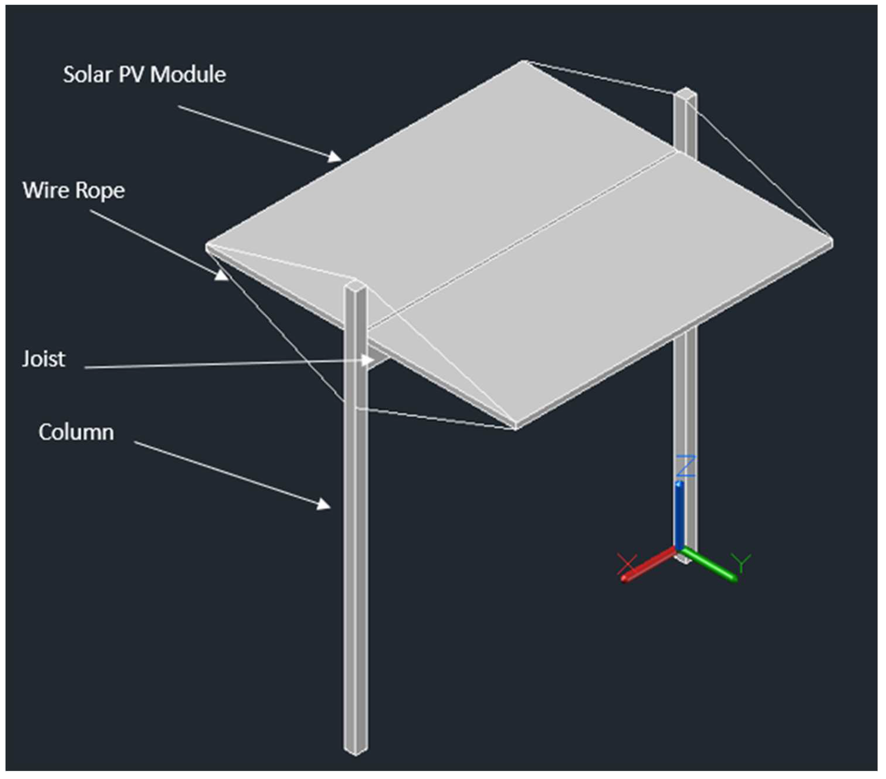
Figure 2.
Cantilevered system with single module.
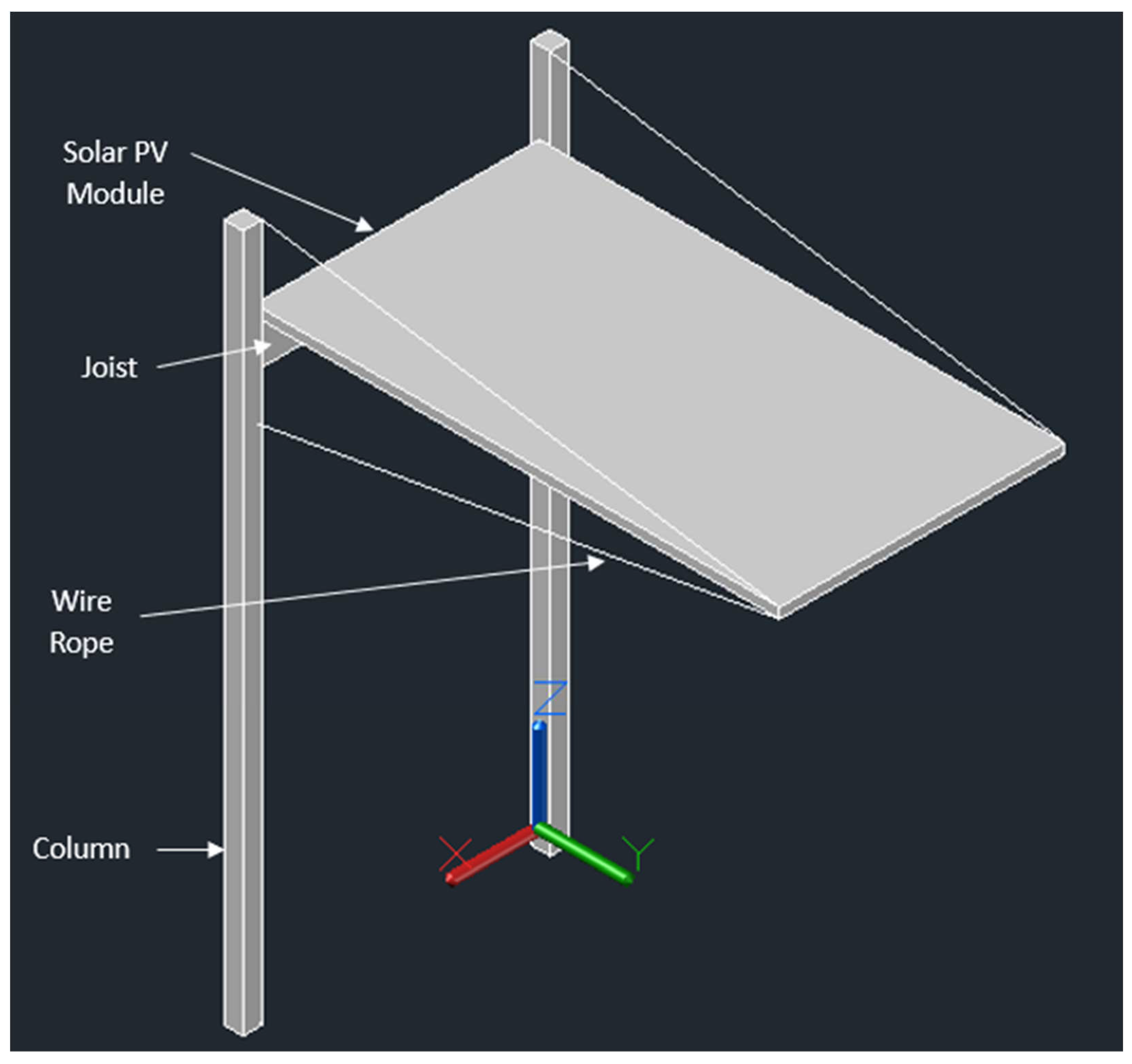
Figure 3.
Cantilevered system with two modules.
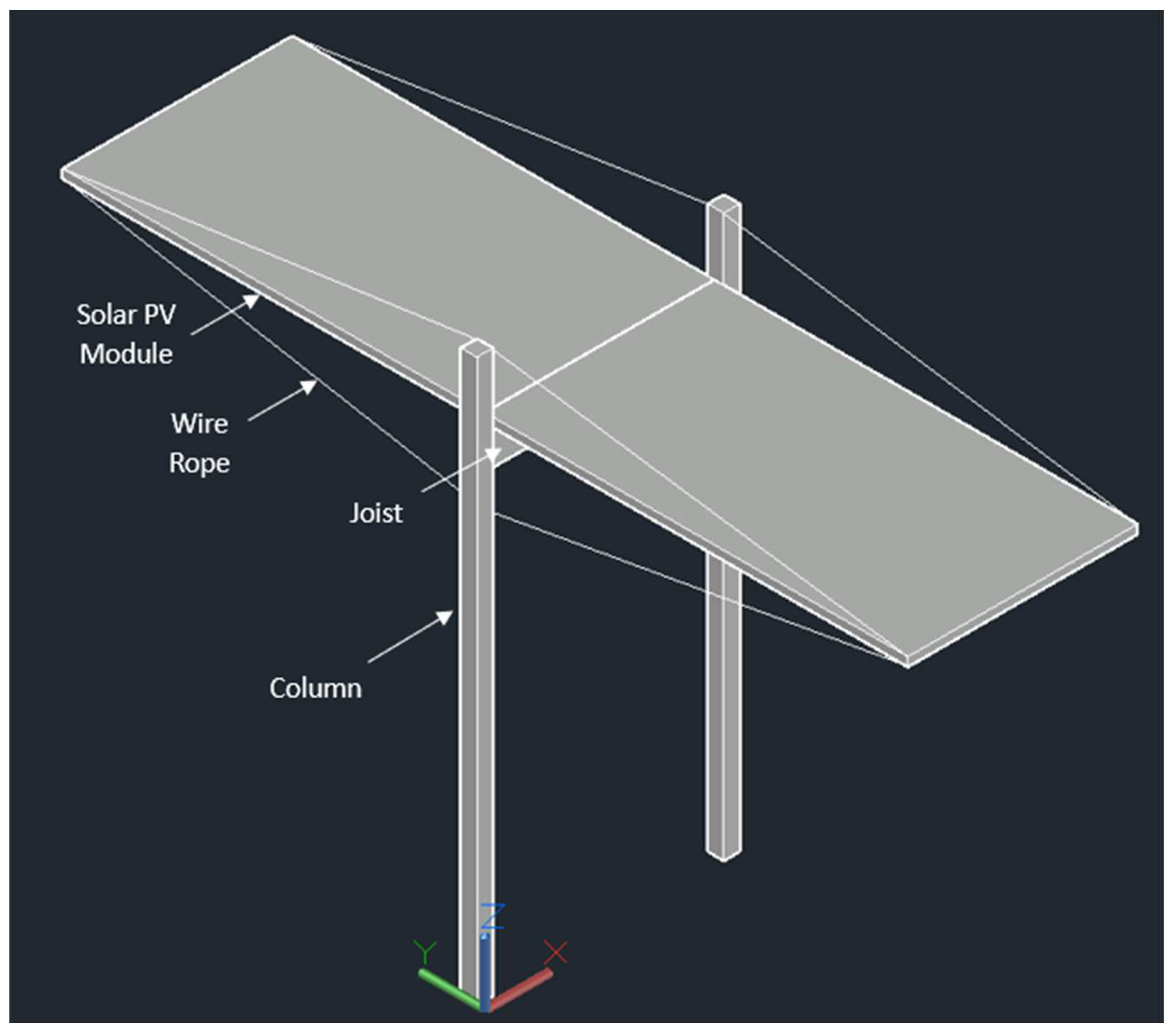
Figure 4.
Attachments for cables: a) eye bolts, b) cable clamp, c) turnbuckle and d) hook.
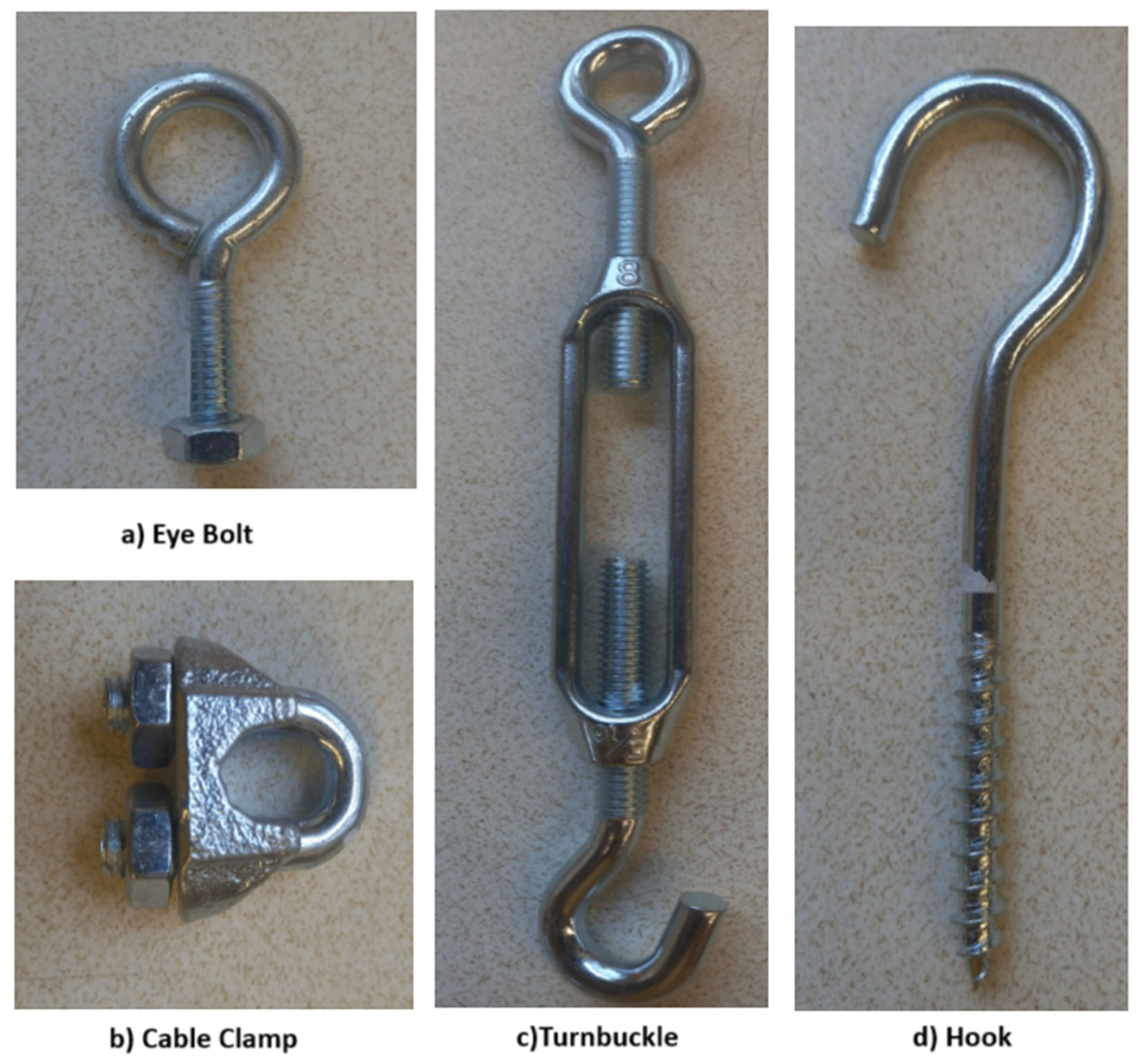
Figure 5.
Boundary conditions for the main FEA model.
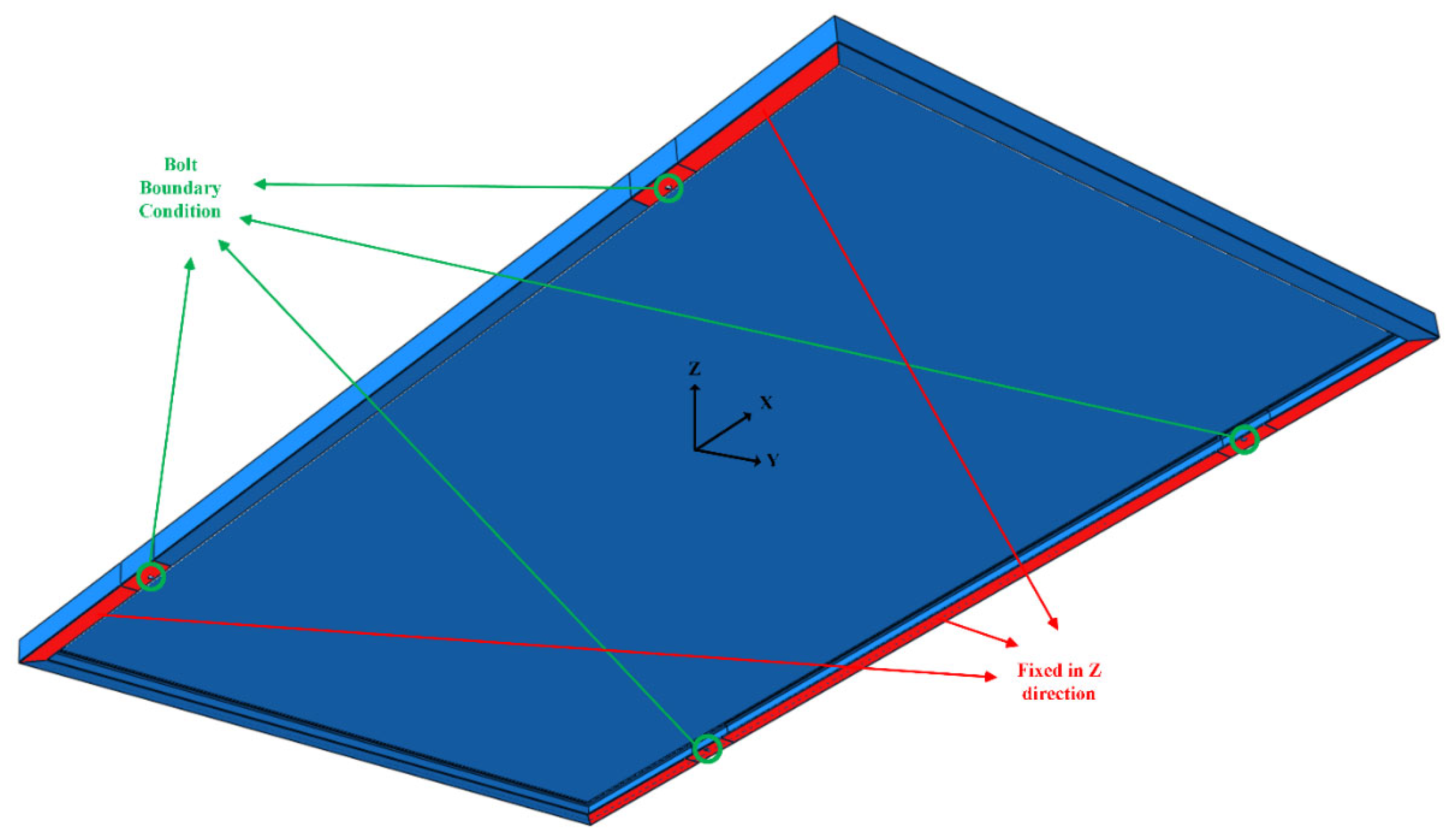
Figure 6.
Boundary conditions for the side bolts FEA model.
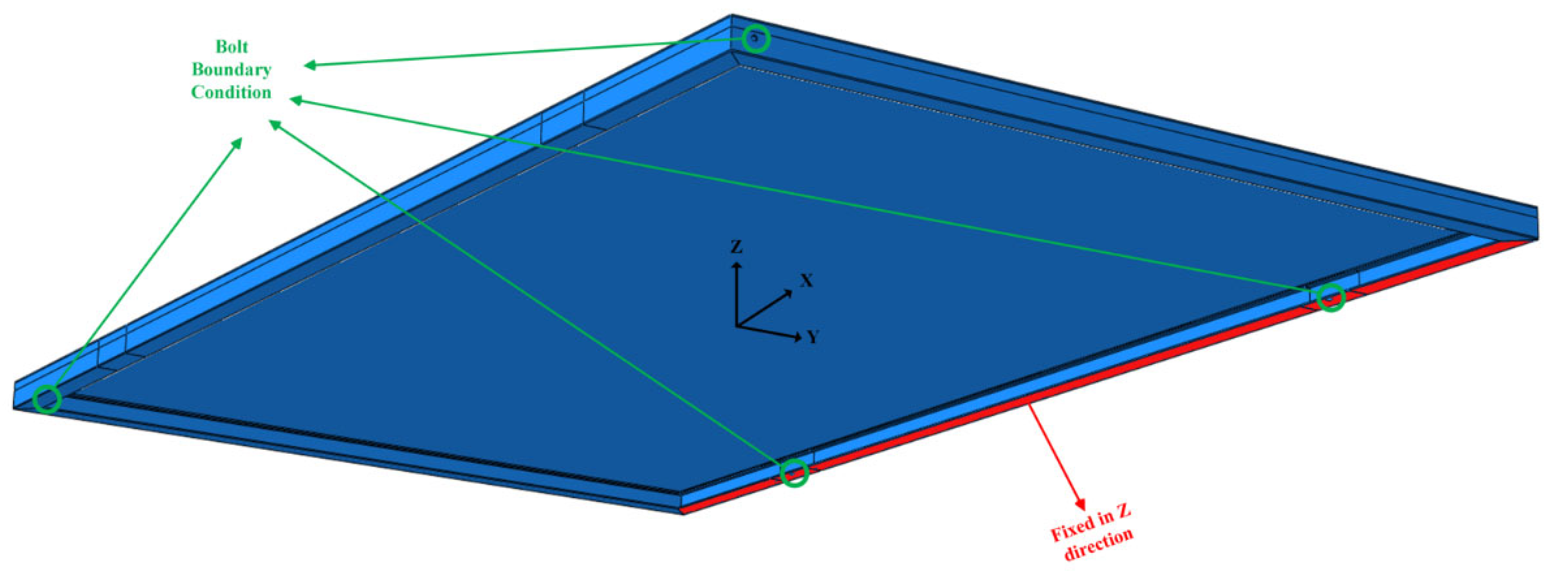
Figure 7.
Bending Moment a) T-shaped and cantilever two module design, b) Cantilever one-module design.
Figure 7.
Bending Moment a) T-shaped and cantilever two module design, b) Cantilever one-module design.
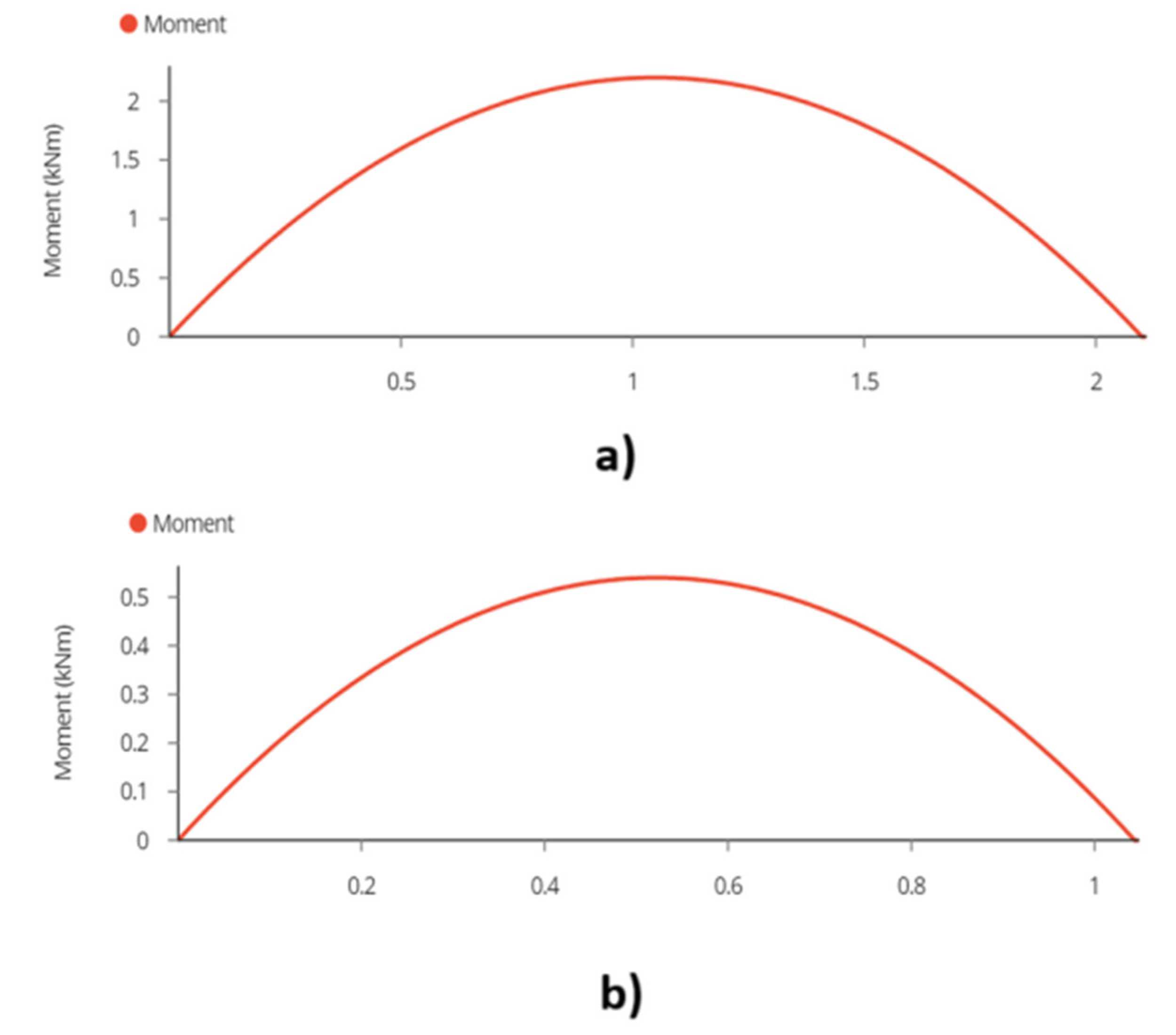
Figure 8.
Maximum Deflection a) T-shaped and cantilever two module design, b) Cantilever one module design.
Figure 8.
Maximum Deflection a) T-shaped and cantilever two module design, b) Cantilever one module design.
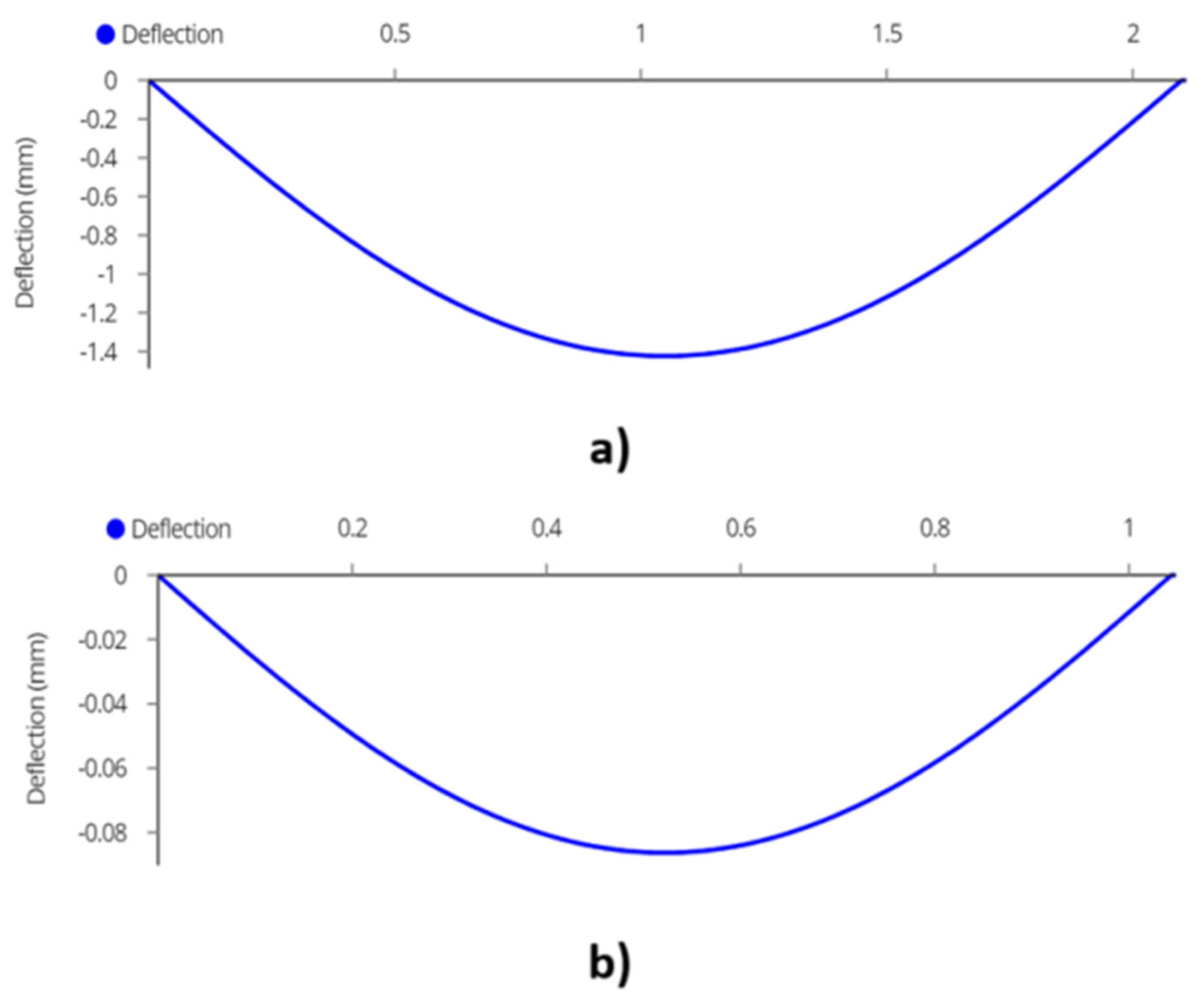
Figure 9.
Reaction and Maximum Shear Forces a) T-shaped design, b) Cantilever designs (one and two module).
Figure 9.
Reaction and Maximum Shear Forces a) T-shaped design, b) Cantilever designs (one and two module).
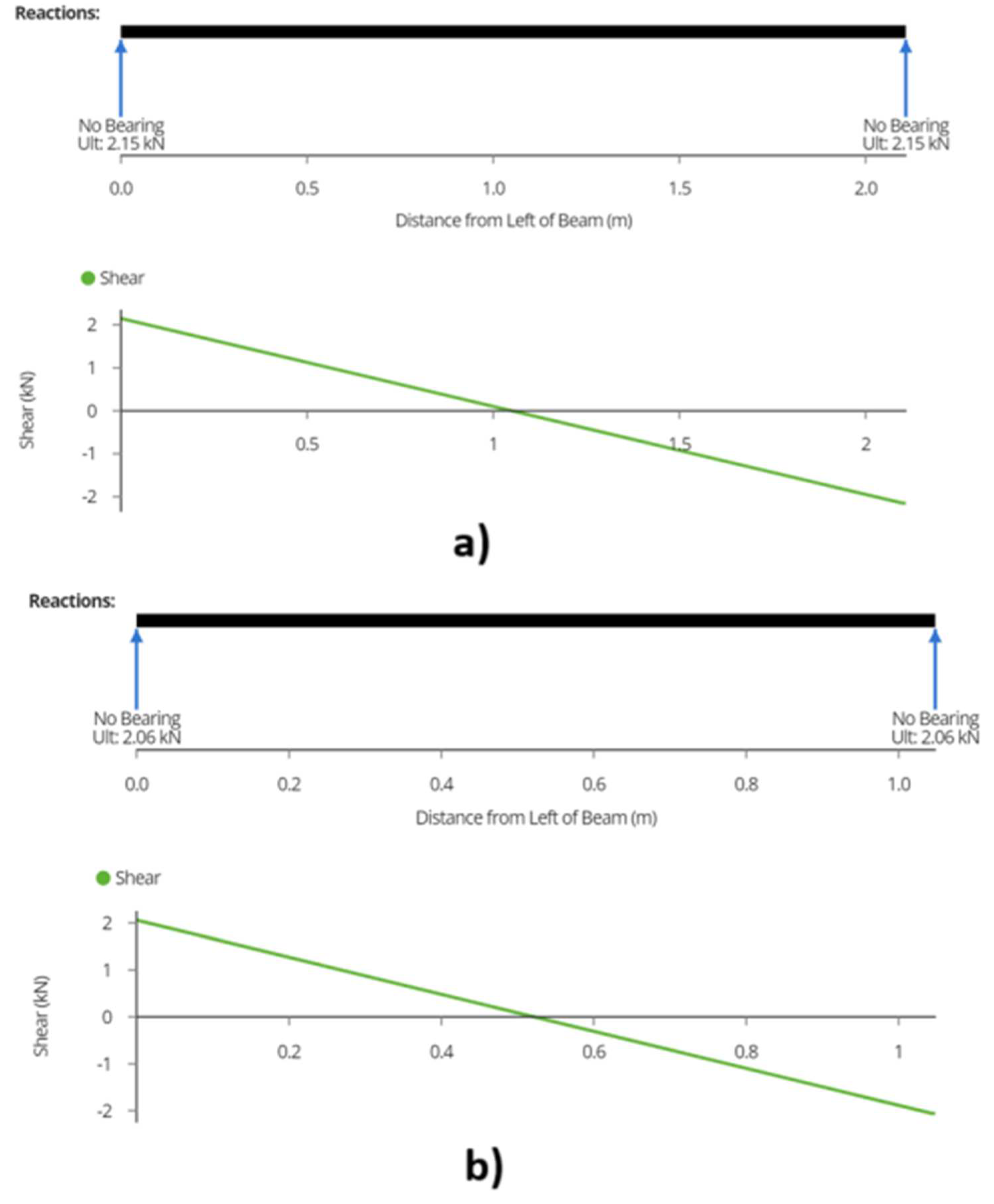
Figure 10.
Graph of force experienced by wire cable at different angles for a) two module design and b) cantilever design.
Figure 10.
Graph of force experienced by wire cable at different angles for a) two module design and b) cantilever design.
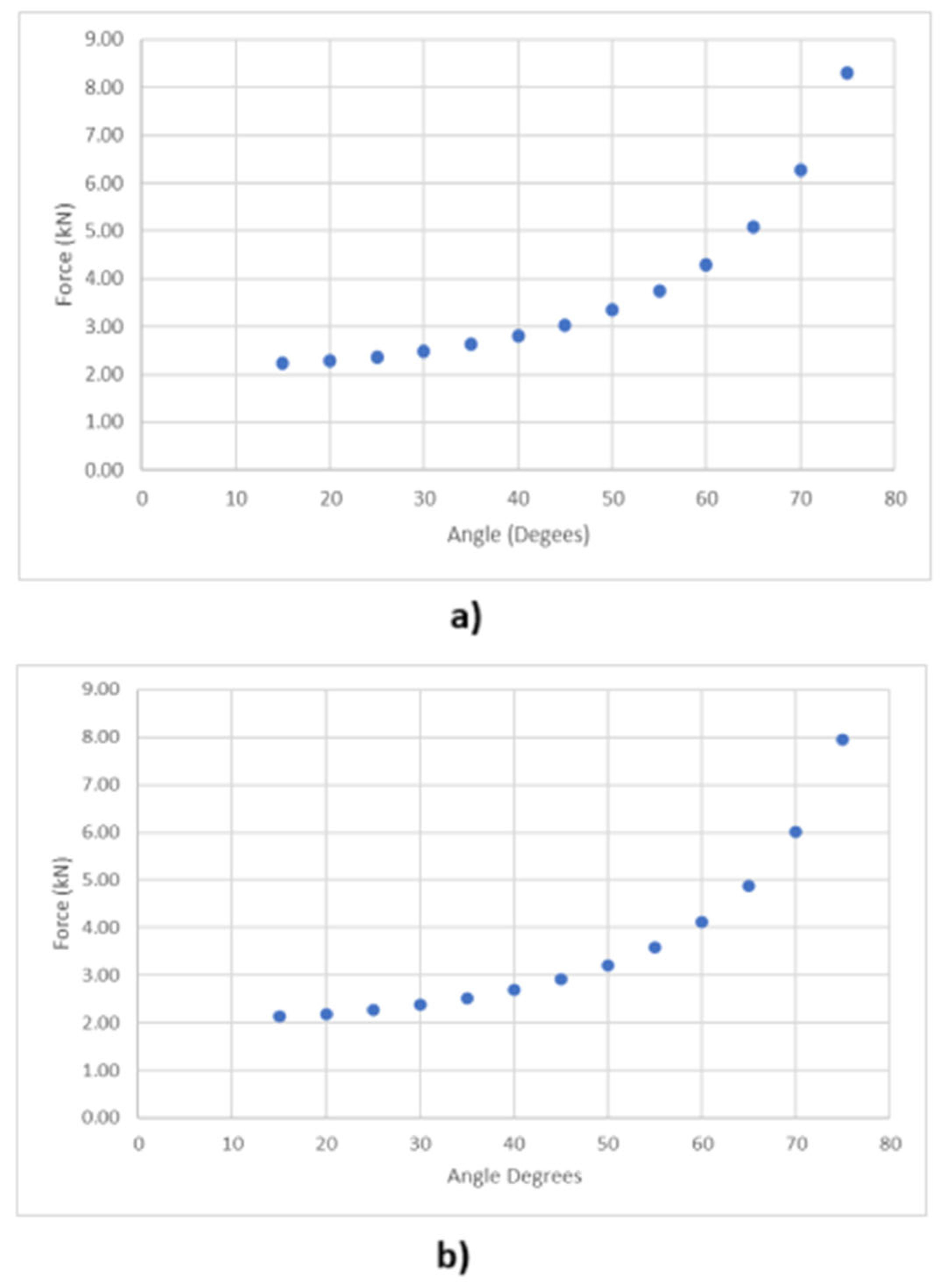
Figure 11.
Truss analysis for the T-shaped two module racking structure.
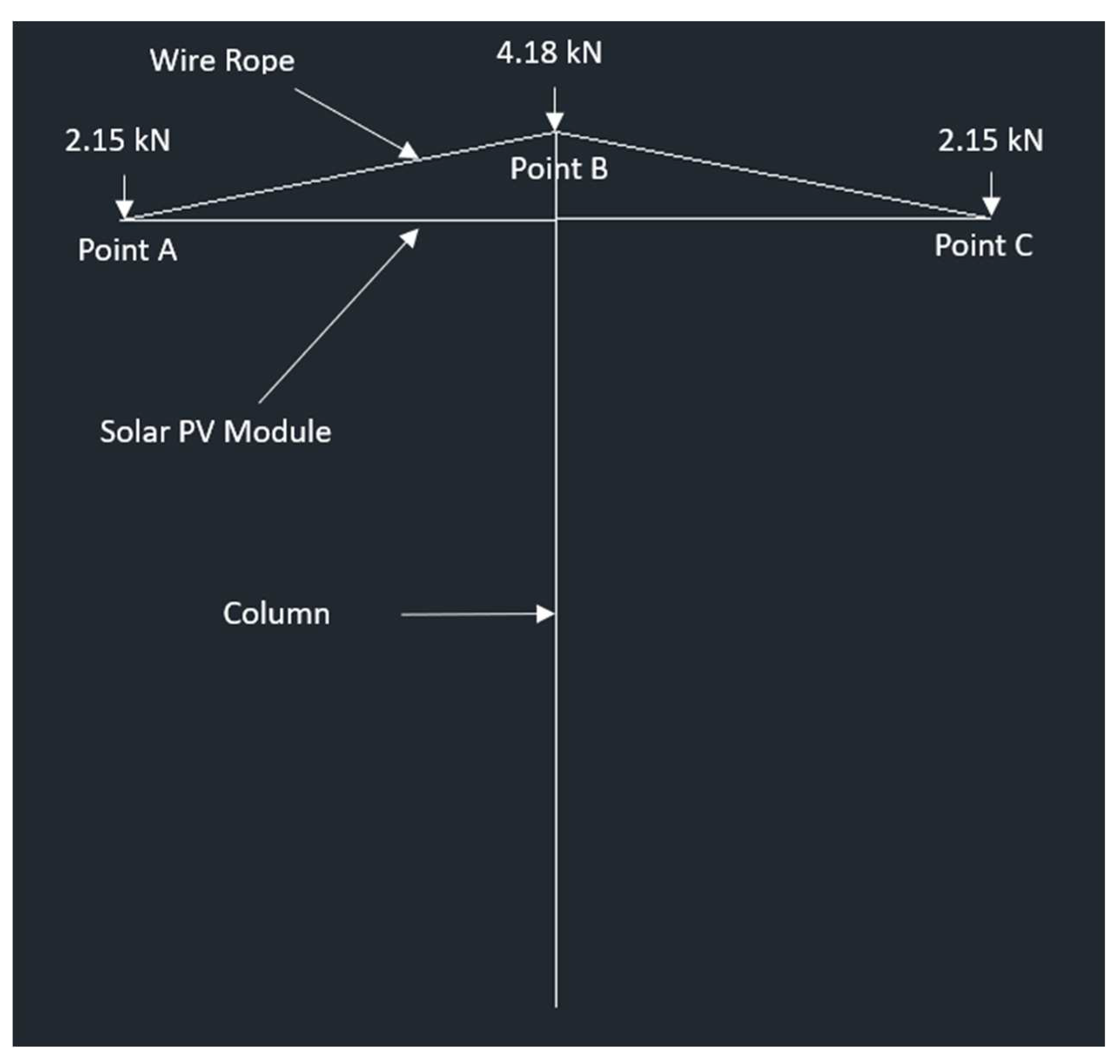
Figure 12.
Truss analysis for the cantilever racking structure.
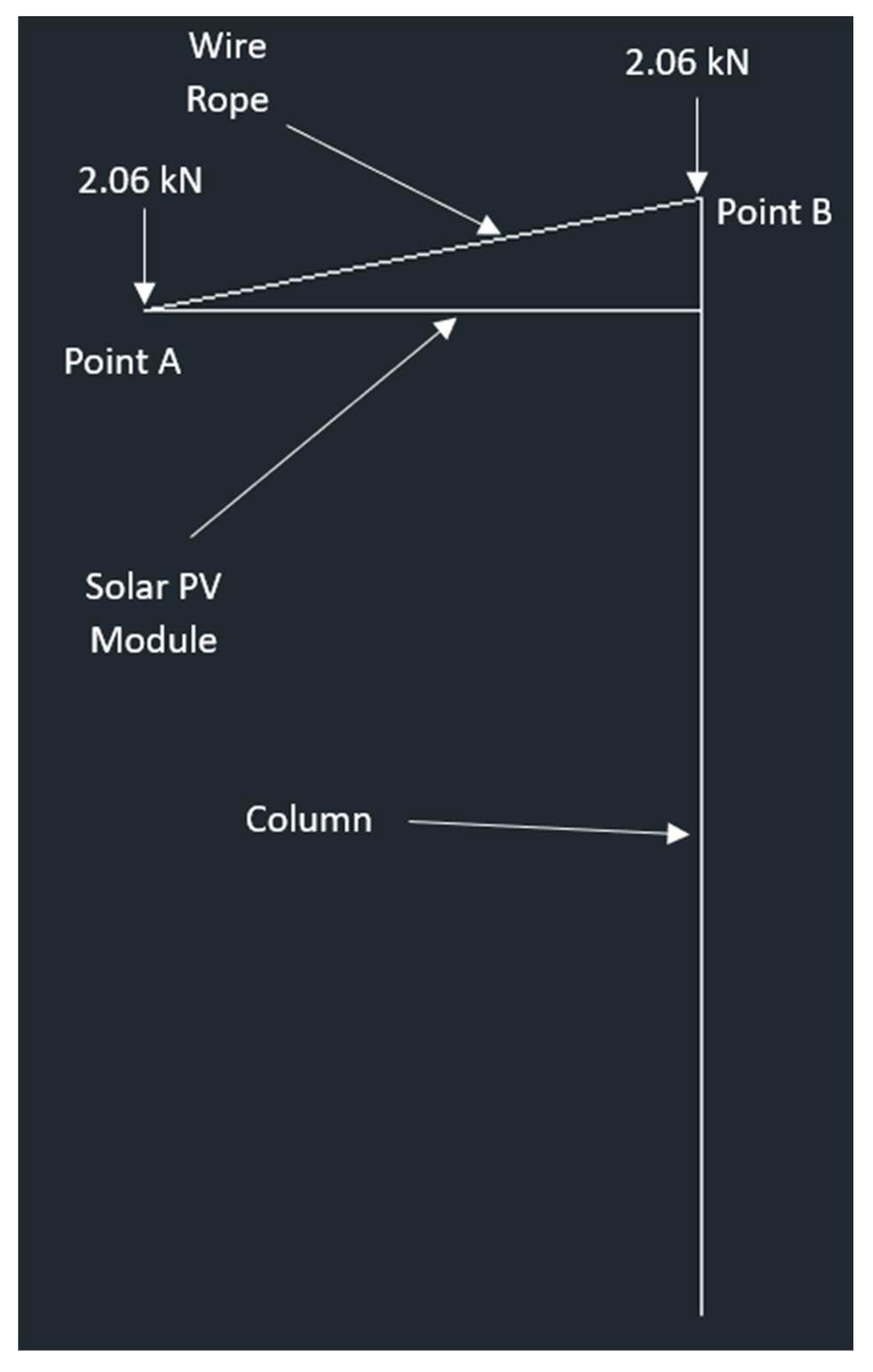
Figure 13.
Stress in MPa (top) and displacement in mm (bottom) of PV module based on FEA results-Main proposed design.
Figure 13.
Stress in MPa (top) and displacement in mm (bottom) of PV module based on FEA results-Main proposed design.
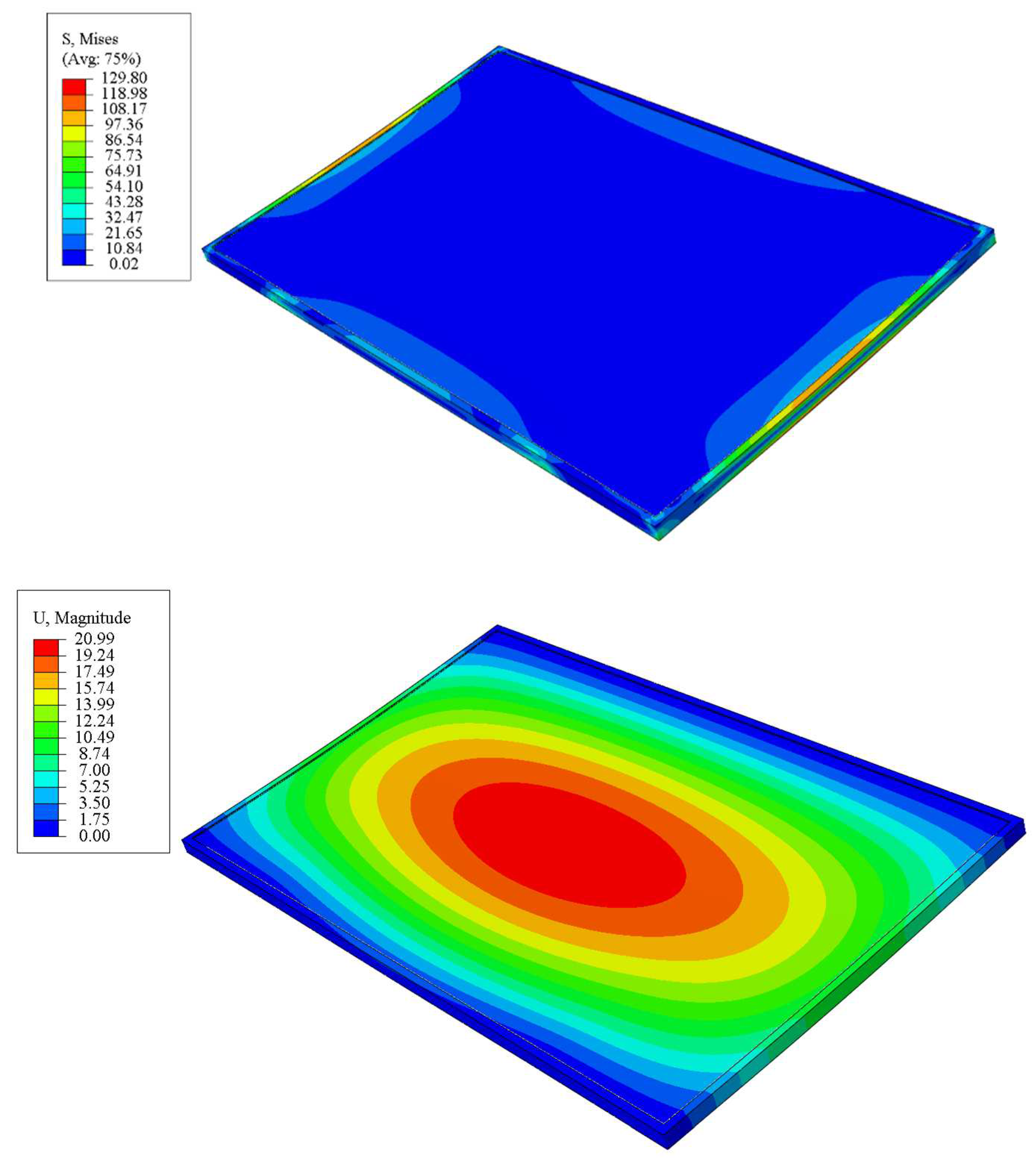
Figure 14.
Stress in MPa (top) and displacement in mm (bottom) of PV module based on FEA results - Main design without fixture.
Figure 14.
Stress in MPa (top) and displacement in mm (bottom) of PV module based on FEA results - Main design without fixture.
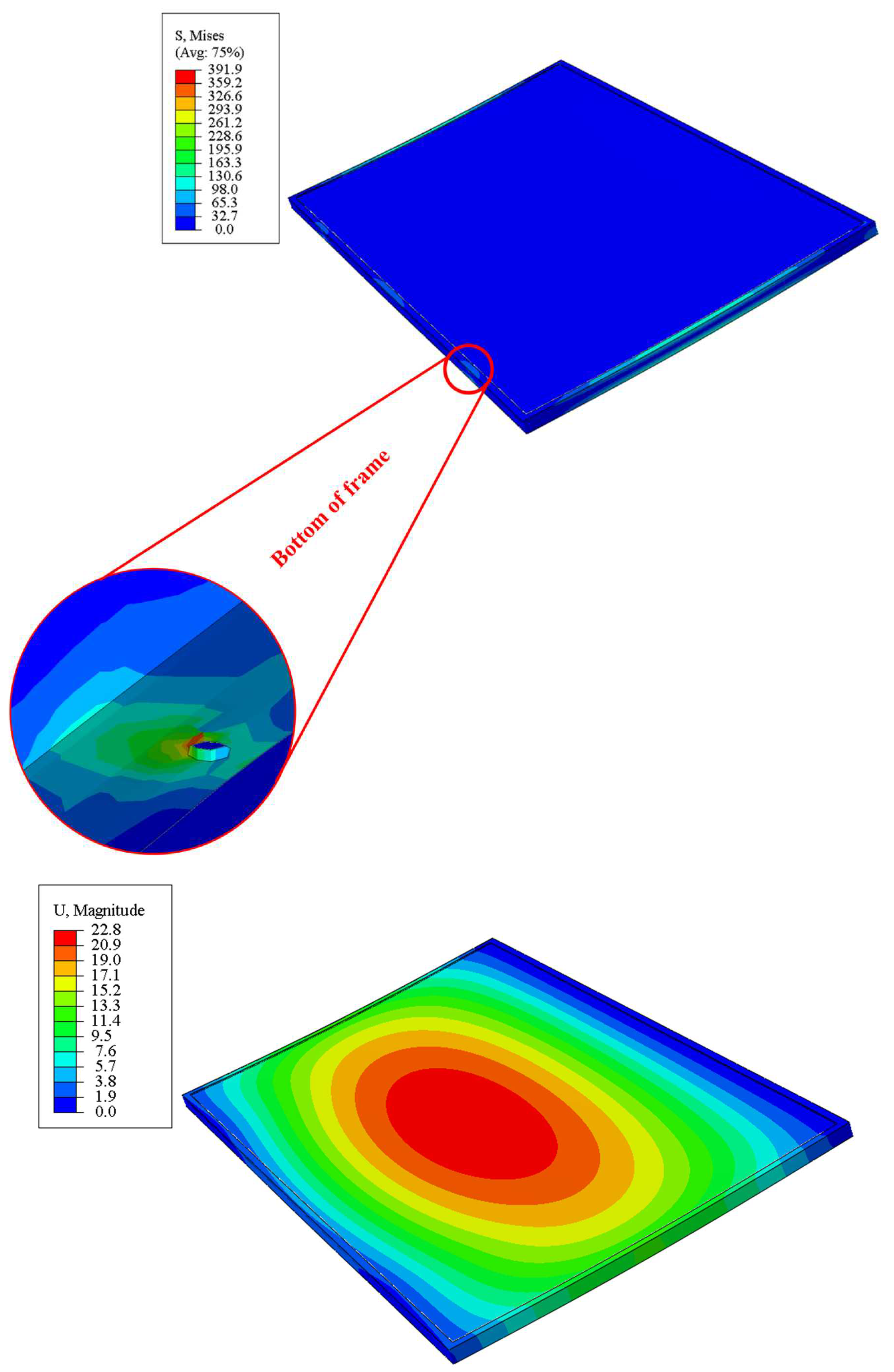
Figure 15.
Stress in MPa (top) and displacement in mm (bottom) of PV module based on FEA results - Side bolts model.
Figure 15.
Stress in MPa (top) and displacement in mm (bottom) of PV module based on FEA results - Side bolts model.
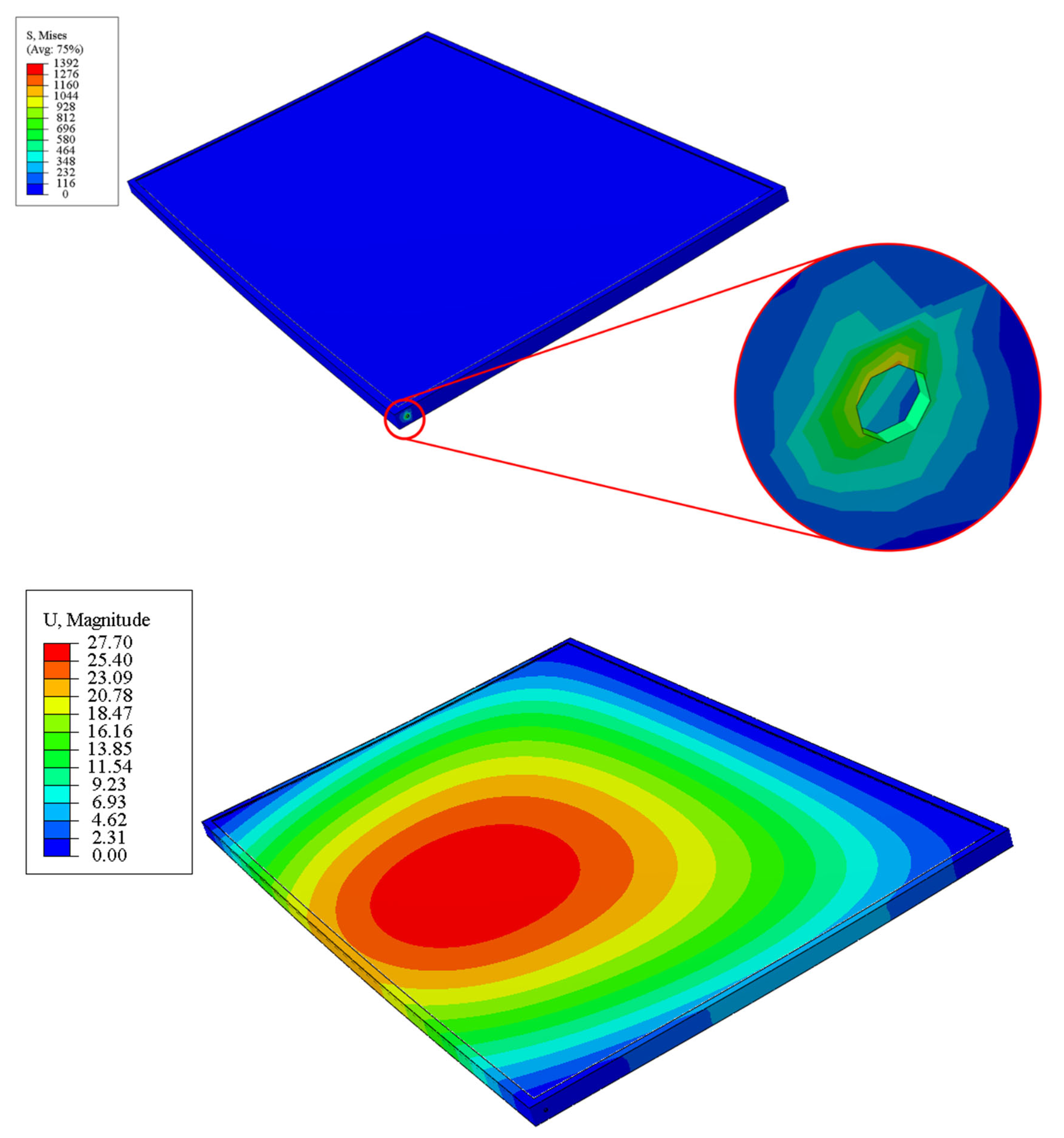
Figure 16.
Proof-of-concept Build of Wire-rope racking design: a)70-degree tilt, b) 45-degree tilt and c) 0o-degree tilt.
Figure 16.
Proof-of-concept Build of Wire-rope racking design: a)70-degree tilt, b) 45-degree tilt and c) 0o-degree tilt.
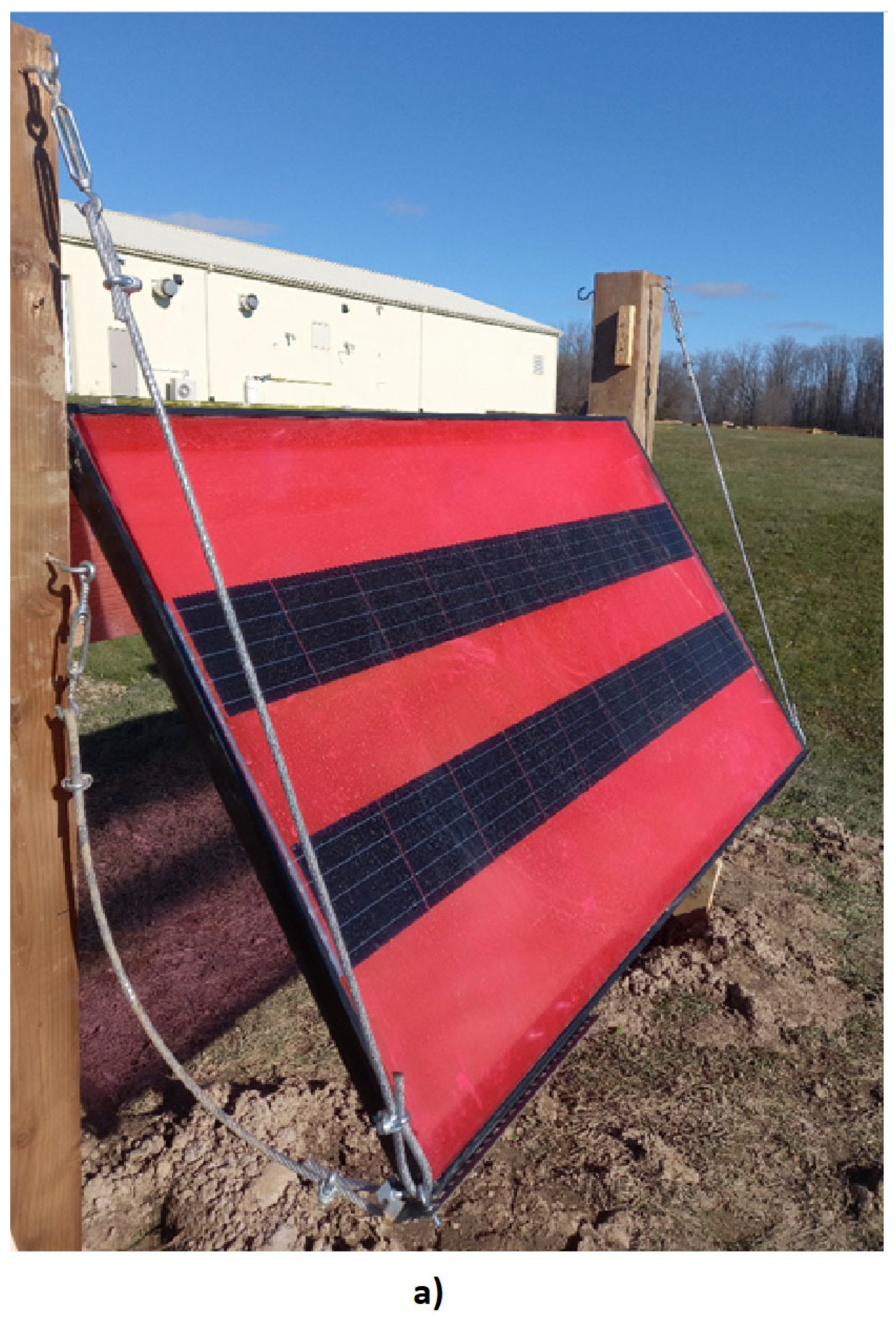
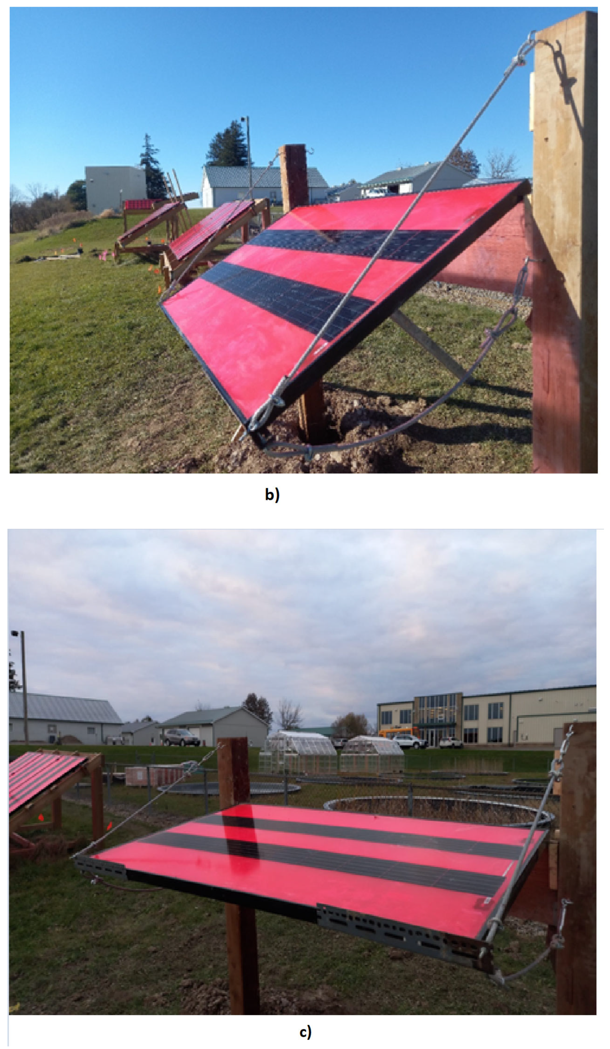
Figure 17.
Hinge for changing the tilt angle of the module.
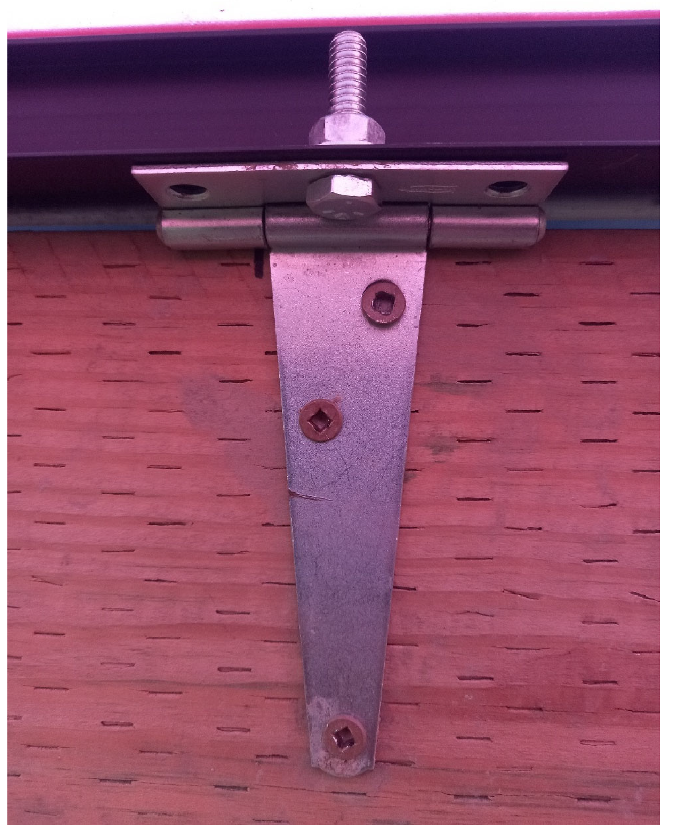
Table 1.
Dimensional characteristics of wood used for the racking.
| Lumber | Lumber Breadth ‘b’ (m) |
Lumber Height ‘h’ (m) |
Area ‘A’ (m2) A=bh |
Moment of Inertia ‘I’ (m4) I=bh3/12 |
First Moment of Area ‘Q’ (m3) Q=hA/8 |
|---|---|---|---|---|---|
| 2x12 | 0.038 | 0.286 | 0.010868 | 7.4079x10-05 | 3.8853 x10-04 |
| 2x4 | 0.038 | 0.089 | 0.003382 | 2.2324x10-06 | 3.7624x10-05 |
| 2x6 | 0.038 | 0.140 | 0.005320 | 8.6893x10-06 | 9.3100 x10-05 |
| 2x8 | 0.038 | 0.184 | 0.006992 | 1.9726x10-05 | 1.6081 x10-04 |
| 2x10 | 0.038 | 0.235 | 0.008930 | 4.1096x10-05 | 2.6232 x10-04 |
| 6x6 | 0.140 | 0.140 | 0.019600 | 3.2013x10-05 | 3.4300 x10-04 |
Table 2.
Breaking strength and workload for galvanized aircraft cable.
| Diameter - Inches (m) |
Breaking Strength – lbs. (N) |
Approx. Wt. / 1000 ft | Workload Limit - lbs. (N) |
|---|---|---|---|
| 1/16 (0.0016) | 480 (2135) | 0.75 | 96 (427) |
| 3/32 (0.0024) | 1000 (4448) | 16.5 | 200 (890) |
| 1/8 (0.0032) | 2000 (8896) | 29 | 400 (1779) |
| 5/32 (0.0040) | 2800 (12455) | 45 | 560 (2491) |
| 3/16 (0.0048) | 4200 (18682) | 65 | 840 (3736) |
| 7/32 (0.0056) | 5600 (24910) | 86 | 1120 (4982) |
| 1/4 (0.0064) | 7000 (31138) | 110 | 1400 (6228) |
| 5/16 (0.0079) | 9800 (43592) | 173 | 1960 (8718) |
| 3/8 (0.0095) | 14400 (64054) | 243 | 2880 (1281) |
Table 3.
Bill of materials (BOM) for wood and cable-based T-shaped variable tilt solar photovoltaic racking system (horizontal modules with cable making 19o angle).
Table 3.
Bill of materials (BOM) for wood and cable-based T-shaped variable tilt solar photovoltaic racking system (horizontal modules with cable making 19o angle).
| Member Name | Piece1 | Cost per Piece2 | Quantity | Cost |
|---|---|---|---|---|
| Joists | 2x12x8 | $35.00 | 1 | $35.00 |
| Posts | 6x6x10 | $52 | 2 | $104.00 |
| Joist to Post Connection | 2x4 Fence Bracket | $0.43 | 2 | $0.86 |
| 7x19 PVC Coated & Galvanized Aircraft Cable | 3/8" | $55.44 | 1 | $55.44 |
| Connections | 2-1/2” Brown Deck Screws | $2.61 | 1 | $2.61 |
| Cable Clamp | 5/16" Wire Rope Clip - Zinc Plated | $1.99 | 16 | $31.84 |
| Turnbuckle | 9-3/8 Turnbuckle | $6.94 | 4 | $27.76 |
| Hooks | 4-3/8 Hooks | $5.22 | 8 | $41.76 |
| Washers | ¼ Washers | $1.90 | 1 | $1.90 |
| Eye Bolts | 1/4x2 Eye Bolts | $1.72 | 8 | $13.76 |
| Hinges | Light-duty (2”) | $2.69 | 4 | $10.76 |
| Nut & Bolt | ¼ inch | $2.78 | 1 | $2.78 |
| Metal fixture | 2” | $8.49 | 1 | $8.49 |
| Total Cost with No Concrete | $336.95 | |||
| Concrete for Posts | 30 MPa Quikrete concrete | $6.38 | 10 bags | $63.80 |
| Total Cost: | $400.75 |
1 All lumber is to be pressure treated, and all hardware is to be hot-dipped galvanized. 2 All costs are in Canadian Dollars as of October 15, 2023, before tax.
Table 4.
Bill of materials (BOM) for wood and cable-based variable tilt carport design with one module (horizontal modules with cable making 19o angle).
Table 4.
Bill of materials (BOM) for wood and cable-based variable tilt carport design with one module (horizontal modules with cable making 19o angle).
| Member Name | Piece1 | Cost per Piece2 | Quantity | Cost |
|---|---|---|---|---|
| Joists | 2x6x8 | $12.78 | 1 | $12.78 |
| Posts | 8x8x10 | $125.33 | 2 | $250.66 |
| Joist to Post Connection | 2x4 Fence Bracket | $0.43 | 2 | $0.86 |
| 7x19 PVC Coated & Galvanized Aircraft Cable | 3/8" | $55.44 | 1 | $55.44 |
| Connections | 2-1/2” Brown Deck Screws | $2.61 | 1 | $2.61 |
| Cable Clamp | 5/16" Wire Rope Clip - Zinc Plated | $1.99 | 8 | $15.92 |
| Turnbuckle | 9-3/8 Turnbuckle | $6.94 | 2 | $13.88 |
| Hooks | 4-3/8 Hooks | $5.22 | 4 | $20.88 |
| Washers | ¼ Washers | $1.90 | 1 | $1.90 |
| Eye Bolts | 1/4x2 Eye Bolts | $1.72 | 4 | $6.88 |
| Hinges | Light-duty (2”) | $2.69 | 2 | $5.38 |
| Nut & Bolt | ¼ inch | $2.78 | 1 | $2.78 |
| Metal Fixture | 2” | $8.49 | 1 | $8.49 |
| Total Cost with No Concrete | $398.45 | |||
| Concrete for Posts | 30 MPa Quikrete concrete | $6.38 | 10 bags | $63.80 |
| Total Cost: | $462.25 |
1 All lumber is to be pressure treated, and all hardware is to be hot-dipped galvanized. 2 All costs are in Canadian Dollars as of October 15, 2023, before tax.
Table 5.
Bill of materials (BOM) for wood and cable-based variable tilt carport design with two modules (horizontal modules with cable making 15o angle).
Table 5.
Bill of materials (BOM) for wood and cable-based variable tilt carport design with two modules (horizontal modules with cable making 15o angle).
| Member Name | Piece1 | Cost per Piece2 | Quantity | Cost |
|---|---|---|---|---|
| Joists | 2x12x8 | $35.00 | 1 | $35.00 |
| Posts | 8x8x10 | $125.33 | 2 | $250.66 |
| Joist to Post Connection | 2x4 Fence Bracket | $0.43 | 2 | $0.86 |
| 7x19 PVC Coated & Galvanized Aircraft Cable | 3/8" | $110.88 | 1 | $110.88 |
| Connections | 2-1/2” Brown Deck Screws | $2.61 | 1 | $2.61 |
| Cable Clamp | 5/16" Wire Rope Clip - Zinc Plated | $1.99 | 16 | $31.84 |
| Turnbuckle | 9-3/8 Turnbuckle | $6.94 | 4 | $27.76 |
| Hooks | 4-3/8 Hooks | $5.22 | 8 | $41.76 |
| Washers | ¼ Washers | $1.90 | 1 | $1.90 |
| Eye Bolts | 1/4x2 Eye Bolts | $1.72 | 8 | $13.76 |
| Metal Fixture | 2” | $8.49 | 1 | $8.49 |
| Nut & Bolt | ¼ inch | $2.78 | 1 | $2.78 |
| Hinges | Light-duty (2”) | $2.69 | 4 | $10.76 |
| Total Cost with No Concrete | $539.05 | |||
| Concrete for Posts | 30 MPa Quikrete concrete | $6.38 | 10 bags | $63.80 |
| Total Cost: | $602.85 |
Table 6.
Materials and mechanical properties of parts used in FEA simulations.
| Material | Thickness [mm] |
Density [tonne/mm3] |
Young’s modulus [MPa] |
Poisson’s ratio [-] |
Strength [MPa] |
Number of elements | |
|---|---|---|---|---|---|---|---|
| Frame | Aluminum (Alloy 6063 [63]) |
1.80 | 2.70E-9 | 70000 | 0.33 | 214 yield 241 tensile |
15980 |
| Sealing | Rubber (Polyurethane elastomer [63]) |
2.00 | 6.70E-11 | 7.40 | 0.30 | 0.0814 – 103 | 3654 |
| Laminate | Glass (soda-lime glass [63]) |
3.2 0 | 2.50E-09 | 70000 | 0.20 | Compressive Strength = 274 | 64288 |
| Solar cells (Czochralski silicon [63]) |
0.18 | 2.329E-9 | 112400 | 0.28 | Compressive Strength = 120 | ||
| Encapsulation (ethylene vinyl acetate [63]) |
0.45 | 9.6E-10 | T-dep. | 0.40 | 3.4-10 | ||
| Backsheet (TPT [63]) | 0.22 | 2.52E-9 | 3500 | 0.29 | Break stress = 132 | ||
Table 7.
Wind, Snow and Dead Load Combination.
| Load Combination | Load [kPa] (upto 15o) | Load [kPa] (30o) | Load [kPa] (upto 45o) | Load [kPa] (60o) |
|---|---|---|---|---|
| 0.9D + 1.4W -0.5S | -2.99 | -2.77 | -2.56 | -2.33 |
| 1.25D + 1.5S – 0.4W | 3.62 | 2.96 | 2.31 | 1.65 |
Table 8.
Structural properties for spruce pine fir Wood.
| Factor | Value (MPa) |
|---|---|
| fb | 6.03 |
| fv | 0.93 |
| ft | 3.10 |
| fc | 7.93 |
| E | 9652.66 |
| Emin | 3516.33 |
Table 9.
Resistance factors.
| Factor | Value |
|---|---|
| CD | 1.15 |
| CT | 1.00 |
| CM | 1.00, 0.97 and 0.90 |
| CL | 0.64. 0.76 |
| Cfu | 1.2 |
| Ci | 1, 0.8 and 0.95 |
| Cr | 1.00 |
| CF | 1.10 |
| CP | 0.29 |
Table 10.
Factored structural properties for spruce pine fir wood .
| Factored Capacities | Value (MPa) |
|---|---|
| fb* | 4.68 |
| fv* | 0.83 |
| ft* | 3.14 |
| fc* | 2.94 |
| E* | 8253.03 |
| Emin* | 3006.46 |
Table 11.
Resisting bending moment, shear force, tensile force, and compressive force for different members of spruce pine fir wood.
Table 11.
Resisting bending moment, shear force, tensile force, and compressive force for different members of spruce pine fir wood.
| Lumber | Resisting Bending Moment ‘Mr’ (kN-m) |
Resisting Shear Force ‘Vr’ (kN) |
Resisting Tensile Force ‘Tr’ (kN) |
Resisting Compressive Force ‘Cr’ (kN) |
|---|---|---|---|---|
| 2x4 | 0.23 | 1.87 | 10.62 | 9.97 |
| 2x6 | 0.58 | 2.95 | 16.70 | 15.69 |
| 2x8 | 1.00 | 3.87 | 21.95 | 20.62 |
| 2x10 | 1.64 | 4.94 | 28.04 | 26.34 |
| 4x10 | 3.27 | 9.89 | 56.08 | 52.67 |
| 2x12 | 2.42 | 6.02 | 34.12 | 32.05 |
| 4x4 | 0.55 | 4.39 | 24.87 | 23.36 |
| 6x6 | 2.14 | 10.85 | 61.54 | 57.80 |
Table 12.
Economic Analysis of different Wood-based PV Racking Designs.
| Racking System | Cost (CAD) | Cost (CAD/Watt) |
|---|---|---|
| Fixed Racking Configuration [43] | 426 (389) | 0.35 (0.32)* |
| Variable Tilt Racking Configuration [44] | 438 (406) | 0.36 (0.34)* |
| Vertical Wood Racking Configuration [45] | 371 (300) | 0.15 (0.13)* |
| T-shaped Racking Configuration (2-module Design) | 397 | 0.43 |
| T-shaped Racking Configuration (4-module Design) | 1155 | 0.63 |
| Sloped Racking Configuration | 372 | 0.40 |
| Inverse Y Racking Configuration | 427 | 0.46 |
| Fixed Racking Configuration (Modified to 1.8m with 6x6 columns) | 526 | 0.44 |
| Variable Tilt Racking Configuration (Modified to 1.8m with 6x6 columns) | 598 | 0.50 |
| Cantilever Carport Racking Configuration (one module) | 471 | 1.00 |
| Cantilever Carport Racking Configuration (two modules) | 612 | 0.66 |
| Variable tilt Wood and Wire Rope T-shaped Configuration | 410 | 0.44 |
* Originally reported values in publications in brackets lower because of economic cost changes.
Table 13.
Difference in wood prices in different parts of the world.
| Country | Price [CAD]1 | Source2 |
|---|---|---|
| Canada | $7.69 | The Home Depot |
| USA | $6.62 | The Home Depot |
| United Kingdom | $5.84 | B & Q |
| Netherlands | $16.04 | Woodvision |
| Australia | $13.29 | Australian Treated Pine Pty Ltd. |
| Brazil | $12.13 | Fremade Madeiras |
| India | $12.45 | IndiaMart |
1 Priced as of November 1, 2023.
Disclaimer/Publisher’s Note: The statements, opinions and data contained in all publications are solely those of the individual author(s) and contributor(s) and not of MDPI and/or the editor(s). MDPI and/or the editor(s) disclaim responsibility for any injury to people or property resulting from any ideas, methods, instructions or products referred to in the content. |
© 2023 by the authors. Licensee MDPI, Basel, Switzerland. This article is an open access article distributed under the terms and conditions of the Creative Commons Attribution (CC BY) license (http://creativecommons.org/licenses/by/4.0/).
Copyright: This open access article is published under a Creative Commons CC BY 4.0 license, which permit the free download, distribution, and reuse, provided that the author and preprint are cited in any reuse.


