
Submitted:
28 November 2023
Posted:
29 November 2023
You are already at the latest version
Abstract
Pistol shrimps generate cavitation bubbles. Cavitation impacts due to bubble collapses are harmful phenomena, as they cause severe damage to hydraulic machineries, such as pumps and valves. However, cavitation impacts can be utilized for mechanical surface treatment to improve the fatigue strength of metallic materials, which is called “cavitation peening”. Through conventional cavitation peening, a cavitation is generated by a submerged water jet, i.e., a cavitating jet or a pulsed laser. The fatigue strength of magnesium alloy when treated by the pulsed laser is larger than that of the jet. In order to drastically increase the processing efficiency of cavitation peening, the mechanism of pistol shrimp (specifically when used to create a cavitation bubble), i.e., alpheus randalli, was quantitatively investigated. It was found that a pulsed water jet generates a cavitation bubble when a shrimp snaps its claws. Furthermore, two types of cavitation generators were developed, namely, one that uses a pulsed laser and one that uses a piezo actuator, and this was achieved by mimicing a pistol shrimp.
Keywords:
cavitation
; cavitation generator
; pistol shrimp
; pulsed laser
; pulsed water jet
; piezo actuator
1. Introduction
Cavitation is a phase change phenomenon, wherein a change from a liquid phase to a gas phase is achieved via a decrease in pressure due to an increase in flow velocity [1]. The phenomenon was discovered as occurring on screw propellers in the 1890s [2]. In nature, pistol shrimp [3,4,5,6,7,8,9,10] and mantis shrimp [11,12,13] are known to create cavitations, and the mechanical properties of their claws has also been investigated [14]. Although there was no term of “cavitation” in the references [15,16], the noise [15] and the water jet velocity [16] of the snapping pistol shrimp claw were measured. Note that there are several types of claws for pistol shrimps [17]. As the impacts induced by cavitation collapse causes severe damage in hydraulic machineries, such as pumps, valves, etc., cavitation is a harmful phenomenon. In order to evaluate the cavitation resistance of materials, cavitation erosion tests were standardized in ASTM International as ASTM G32 [18] and G134 [19]. As per ASTM G32 and G134, cavitation is generated by a vibratory horn at an ultrasonic band, i.e., ultrasonic cavitation, and a submerged high-speed water jet with cavitation, i.e., a cavitating jet. On the other hand, cavitation impacts can be utilized for mechanical surface treatment to improve fatigue strength, which is called cavitation peening [20]. It is worthwhile to develop a novel cavitation generator for mechanical surface treatment by mimicing a pistol shrimp.
In conventional mechanical surface treatments, shot peening (in which shots are impinged to target materials), is used [21,22,23,24,25,26,27,28]. Shot peening can improve the fatigue properties of metallic materials [29,30,31,32,33]; however, the surface roughness is increased by solid collisions [34,35]. When the fatigue strength of peened stainless steel was compared, the fatigue strength of cavitation peening was found to be better than that of shot peening [36]. The residual stress and the relaxation in the compressive residual stress introduced by peening were discussed in the fatigue life of peened stainless steel [37]. It was reported that the relaxation of cavitation peening was less than that of shot peening [38]. As the dislocation density of cavitation-peened stainless steel was also smaller than that of shot peening at equivalent compressive residual stress condition [39], it was found that this is one of reasons why the relaxation of cavitation peening is less than that of shot peening. It was also reported that the yield stress of stainless steel increases with the strain rate [40,41,42,43]. Cavitation peening is a kind of shockwave process that occurs at bubble collapse; thus, the strain rate of cavitation peening is larger than that of shot peening. Thus, cavitation peening can treat metallic materials with a small increase in dislocation density, thereby resulting in a lesser relaxation in the compressive residual stresses than shot peening. As such, it is worthwhile to develop cavitation peening in order to improve the fatigue strength of metallic materials.
In conventional cavitation peening, cavitation is produced by a cavitating jet [44]. When the jet impinges to the target, a cloud cavitation is generated near a nozzle and becomes a ring vortex cavitation. Then, a part of the ring vortex cavitation collapses as a longitudinal vortex cavitation generates impacts [44]. Specifically, it is vortex cavitations [45], which are similar to horseshoe cavitations [46,47], that generate severe impacts. Unfortunately, it is 1/1000–1/100 of vortex cavitations that generate intense cavitation [20], and the mechanism for them is not clear. In another way to conduct cavitation peening, a cavitation is generated by a submerged pulsed laser, i.e., laser cavitation peening [48,49,50]. In the case of magnesium alloy, the fatigue strength of laser cavitation peening is better than cavitation peening conducted via a cavitating jet [51]. Laser cavitation peening is similar to laser peening, which is also called laser shock peening. Note that there are two types of laser peening. One is laser peening with a water film, in which a target is covered with a water film [52,53,54,55,56,57,58]. The other is submerged laser peening, in which target is placed in water [36,59,60,61,62,63]. In both laser peening methods, the pulsed laser is irradiated to the target surface, which covers a confining medium such as water. The shock wave at laser ablation is then concentrated into the target materials by the confining medium, which then produces plastic deformation [62]. In submerged laser peening, a bubble that behaves like a cavitation bubble is generated after laser ablation, which then collapses [36,64]. The bubble induced by a pulsed laser is called laser cavitation [48].
In the case of submerged laser peening, when the amplitude of pressure in water is measured by a submerged shockwave sensor, the amplitude of laser ablation is larger than that of laser cavitation collapse [36,64]. On the other hand, the impact passing through the target has been measured by a sensor with a polyvinylidene fluoride PVDF film [65], and it has been found that the impact at a laser cavitation collapse is larger than that of laser ablation [36,49,66]. Namely, laser cavitation is applicable for cavitation peening. Unfortunately, it takes time to improve the fatigue strength by laser cavitation peening as the repetition frequency of the pulsed laser is about several dozen times per second. Although a high-repetition portable pulse laser, whose power and pulse width are 10 mJ and 1.3 ns, was developed in [67], its repetition frequency was only about 100 Hz, and 800–1600 pulses/mm2 were required for treatment. Even then, it still requires a long time to treat the target.
Cavitation peening using an ultrasonic vibratory horn has also been proposed [68,69,70,71,72]; however, the aggressive intensity of ultrasonic cavitation is particularly sensitive to the standoff distance between the horn and target surface. For example, the cavitation intensity was reduced to approximately 20% from 0.8 mm to 1.0 mm. And, also, even though the vibratory frequency was 20 kHz, the intense cavitation impact occurred several times per second [73]. Furthermore, when considering cavitation peening with cavitating jets, submerged pulsed lasers, and ultrasonic vibratory horns, it is worthwhile to develop a novel cavitation generator, which can be used to drastically increase the processing efficiency of cavitation peening.
From the view point of mechanical devices that are bioinspired by pistol shrimp, a pulsed water jet generator was proposed [74,75], and a ring vortex cavitation around the pulsed water jet from a device was realized by mimicing the claws of pistol shrimp [76]. A bioinspired plasma generator [77] and an impulsive motion generator [78] were also developed. When the claw of a pistol shrimp is imitated, high-repetition frequencies, such as several hundred times per second, are not expected. As such, a cavitation generator for peening was developed by mimicing the essential mechanism in the generation of cavitations by pistol shrimp, which is a pulsed water jet that generates cavitation.
In the present paper, in the first part, a pistol shrimp claw, i.e., alpheus randalli, was measured by a μCT, and the volume of the pulsed water jet was also estimated. Then, a cavitation bubble induced by a pistol shrimp was evaluated by comparing the noise created by laser cavitation. In the second part, a pulsed water jet is produced by mimicing a pistol shrimp, and two cavitation generators are developed using a pulsed laser and a piezo actuator.
2. Materials and Methods
Figure 1 shows an examined pistol shrimp, i.e., alpheus randalli. The length of its body without whiskers was about 35 mm. As shown in Figure 1, the right-hand side claw was bigger than the left-hand side, as it created cavitation. Figure 2 reveals the right-hand side claw of the pistol shrimp, which was its shed shell. The three-dimensional shape of the claw was measured by a dental μCT apparatus. Figure 3 illustrates the schematics of the measurement of the noise that was generated by the pistol shrimp. The noise was detected by a hydrophone (Miniature Hydrophone Type 8103, Brüel & Kjær, HBK Company, Denmark), and the signal was connected to a pre-amplifier (Charge conditioning amplifier 2692, Brüel & Kjær, HBK Company, Denmark). Then, the signal was recorded by a digital oscilloscope (DPO3054, Tektronix, Inc., Beaverton, OR, USA). Artificial sea water (Instant ocean, Spectrum Brands, Inc., Blacksburg, VA, USA) was also used in the present experiment.
Figure 4 shows schematics of a submerged pulsed laser system, which was used to compare laser cavitation with the cavitation generated by a pistol shrimp. The used laser pulse source was a Q-switched Nd:YAG laser with a wavelength conversion (SureliteTM SL I-10, Continuum®, Amplitude Laser Inc., San Jose, CA, USA). By controlling the wavelength conversion, both 532 nm and 1,064 nm wavelengths could be obtained. The pulse width, beam diameter, and the repetition frequency of the laser pulse were 6 ns, 6 mm, and 10 Hz, respectively. The maximum energy was 0.2 J at 532 nm and 0.35 J at 1,064 nm. For the purposes of comparing the laser cavitation with the cavitation generated by the pistol shrimp, a 532 nm measurement was used to avoid the attenuation of the laser power by water. The pulsed laser from the laser source was reflected by mirrors, and it was expanded by a concave lens to avoid damage to the chamber. This was then focused by a convex lens of 100 mm at focal distance, and this was then finally focused by a convex lens of 15 mm at focus distance, which was next placed into water.
The maximum diameter of laser cavitation dmax was controlled by laser power. The dmax was measured by using a high-speed video camera (VW9000, Keyence Corporation, Osaka, Japan). Once the relationship between tD and dmax was obtained, dmax can be obtained from tD. Here, tD was defined by the time between the laser ablation and laser cavitation collapse. With respect to Rayleigh [79], the collapse time tc for a bubble from radius R0 to collapse is given by Equation (1).
As such, Equation (2) is obtained from Equation (1).
Here, k1 [mm/μs] is a proportional constant; furthermore, it is 0.0111 for a p = 0.1013 MPa and ρ = 998 kg/m3 of water, and it is 0.0110 for a p = 0.1013 Mpa and ρ = 1,003 kg/m3 of sea water.
In the case of dmax, Equation (2) denoted Equation (3).
Specifically, dmax can be obtained from tD.
Figure 5 illustrates the schematics of a cavitation generator by using the pulsed laser. The used pulsed laser was a Q-switched Nd:YAG laser with a wavelength conversion that was same as detailed in Figure 4. For the cavitation generator, the wavelength of the used pulsed laser was 1,064 nm. The acrylic chamber was 10 mm in diameter and 12 mm in the length, with the nozzle having a diameter of 0.5 mm. When the pulsed laser was irradiated in the acrylic chamber, a laser cavitation was generated, and the volume expansion of the laser cavitation produced a pulsed jet through the nozzle. Then, the cavitation was able to be generated around the pulsed jet.
Figure 6 shows the schematics of a cavitation generator that uses a piezo actuator. The used piezo actuator was a metal-case-type piezoelectric actuator (AHB101C801 ND0LF, TOKIN Corporation, Sendai, Japan). The actuator was operated by a high-voltage power supply (PZDR-0.15P6A, Matsusada Precision Inc., Shiga, Japan). The used signal for the power supply was generated by a transistor–transistor logic TTL signal generator (AN-PGV100, IDT Japan, Inc., Tokyo, Japan). The chamber was made by an acrylic pipe, whose inner and outer diameter were 26 mm and 30 mm, and whose length was 20 mm. In order to fill the water into the chamber, a syringe was connected to the chamber though a 0.56 mm diameter needle. The diaphragm was made by a polytetrafluoroethylene PTFE sheet of 1 mm thickness. When the piezo actuator expanded, a pulsed water jet was generated through the nozzle (whose diameter was 0.6 mm). As the aggressive intensity of the cavitating jet was strongly affected by the nozzle exit [80], the nozzle had an outlet bore that was 2 mm in diameter and 1 mm in length. The movement of the piezo actuator and the aspect of the cavitation were observed by a high-speed video camera (OS8-V3 S3, IDT Japan, Inc., Tokyo, Japan).
3. Results
3.1. Cavitation Induced by Pistol Shrimp Comparing with a Pulsed Laser
Figure 7 shows the diagonal view of the opened claw that was measured by the μCT. Figure 8 reveals the aspects of the x, y, and z cross-sections of the closed claw that was measured by the μCT. Figure 8 shows that the movable part of the claw, which had a convex part, and the concave part of the fixed side had a shape into which the convex part was inserted. It has been reported that there are several types of pistol shrimps [17]. Some of them have a deep fossa and a large plunger. In the case of alpheus randalli, the convex and concave parts were relatively shallow when compared with the reported one [3]. Figure 7 reveals that the convex hull had a height and width of about 1 mm; on the other hand, Figure 8 shows that the volume of the concavo-convex mating area was much smaller than that. If the concavo-convex mating area is assumed to be a semi-ellipsoid, its height, width, and depth are estimated to be about 0.48 mm, 0.48 mm, and 0.72 mm, respectively, and its volume is estimated to be about 0.35 mm3.
Figure 9 shows the sound pressure pN changing with time t for the pistol shrimp (a) and for the pulsed laser (b). To measure the sound pressure pN, the hydrophone was horizontally placed at a distance of 50 mm from the laser focus point. When the difference from the noise source to the hydrophone, i.e., 50 mm for the pulsed laser and 90 mm for the pistol shrimp, was considered, the noise ratio of the pistol shrimp to the pulsed laser was found to be (90/50)2 ≈ 3.2. Thus, the pN of the shrimp was nearly equivalent to that of the pulsed laser. In Figure 9, the peak value was 7.7 kPa for the pistol shrimp and 25 kPa for the pulsed laser. It was then found that the noise levels of the pistol shrimp and the pulsed laser were similar. Thus, it was worthwhile to compare the noise level of the pistol shrimp with that of the pulsed laser.
It was reported that the aggressive intensity of the cavitation bubble collapse was proportional to the volume of cavitation [44,45,81], and the volume of bubble should be considered to compare the aggressive intensity of the cavitation induced by the pistol shrimp and the pulsed laser cavitation. As mentioned in the introduction as Equation (3), the developing time tD from initiation to collapse was found to be proportional to the maximum diameter dmax. In order to confirm the relation between tD and dmax, Figure 10 helped to revealed the relation between the tD and dmax of the laser cavitation for water and sea water. As shown in Figure 10, hemispherical bubbles on the flat specimen were also revealed. As shown in Figure 10, the dmax was proportional to tD, and the proportional constant of sea water was slightly smaller than that of water. The proportional constant was about 0.0106 for water and 0.0089 for sea water. As such, it can be concluded that the dmax can be estimated by tD. Thus, in the present paper, tD was used as a parameter for bubble size.
The tD in reference [3] was about 750 μs, and the maximum bubble was estimated to be about 7 mm from the relation between tD and dmax for the sea water, as shown in Figure 10. This corresponded to the longitudinal length of the flattened cavitation that was produced by the pistol shrimp in the reference of [3]. As such, tD of the bubble that was induced by the pistol shrimp can be used for the size of bubble that was produced by the pistol shrimp.
In the case of Figure 9 (a), tD was about 300 μs, the maximum bubble size was about 2.7 mm in diameter, and thus the volume of the bubble was about 10 mm3. As mentioned above, the volume of the concavo-convex mating area was about 0.35 mm3. Thus, it can be said that the volume of the created cavitation was 30 times larger than the volume of the droplet.
As tD can be used for determining the size of cavitation parameter, as is shown in Figure 10, Figure 11 reveals the relation between tD and pNmax, which was the peak value of the pN of the pistol shrimp and the pulsed laser. For both cases, coral sand was placed near the bubbles, and the distance between the source of the bubbles and the hydrophone was 90 mm. The pNmax of both cases was roughly proportional to the tD. When comparing the pistol shrimp and the pulsed laser, the pistol shrimp showed a tendency for the pNmax to be higher than that of the pulsed laser when there was an equivalent tD.
It has been reported that the aggressive intensity of the laser cavitation collapse of degassed water is greater than that of saturated water [48] (which is called the cushion effect). In the case of the pulsed laser, heat was concentrated into the bubble, then the temperature inside the bubble was raised, which caused vapor to form inside the bubble and caused the vapor act as a cushion effect when the bubble collapsed. Specifically, the pNmax of the pulsed laser was slightly lower than that of the pistol shrimp, and this was due to the cushion effect.
3.2. Development of Cavitation Generator Mimicing Pistol Shrimp
3.2.1. Cavitation generator using pulsed laser
Figure 12 reveals the aspect of the cavitation that was induced by the cavitation generator using a pulsed laser, which is shown in Figure 4. As shown in Figure 12, the parallel part of the left-hand side is the nozzle, the diameter of which was 0.5 mm; in addition, the pulsed laser was irradiated in the water-filled chamber, which was placed on the left-hand side of the nozzle. When the pulsed laser was irradiated in the chamber, a laser-induced bubble was generated in the chamber, and the expansion of the bubble also pushed the water. Thus, a pulsed water jet was accelerated through the nozzle. When the pulsed water jet reached the end of the nozzle, a ring vortex cavitation was generated. Then, the ring vortex cavitation shed from the nozzle to downstream. As shown in Figure 12, when the light source was placed on the other hand of the high-speed video camera, a ring vortex cavitation was observed via a black shape. After t = 0.070 ms, the ring vortex cavitation shrunk and then developed again, which then finally collapsed at t = 0.200 ms. By measuring the movement of the droplet in the nozzle, the velocity of the pulsed water jet was found to be about 29 m/s. Thus, it can be said that the pulsed water jet was accelerated by the expansion of the laser-induced bubble, which generated the cavitation bubble. The shedding velocity of the ring vortex cavitation was about 20 m/s.
When the pulsed water jet of the droplet, which was 0.5 mm in diameter and 0.5 mm in length, was considered, the energy of the droplet was 1/2 × π × 0.000252 × 0.0005 × 998 [kg/m3] × 292 ≈ 166 [mJ] at v = 29 m/s. The energy of the used pulsed laser was about 350 mJ. Thus, nearly half of the pulsed laser energy produced the pulse water jet. When the energy of the pulsed water jet that was produced by the claw, which was 0.35 mm3 in volume and 29 m/s in velocity, was considered, the energy of the pulsed water jet was 0.16 mJ. Specifically, the pistol shrimp created cavitation bubbles particularly efficiently.
3.2.2. A cavitation generator using a piezo actuator
As shown in Figure 12, the submerged pulsed water jet can create a cavitation bubble using a pulsed laser; however, the repetition frequency cannot be increased when compared with a conventional laser cavitation peening system, and this is because the Q-switched Nd:YAG laser is used for the cavitation generator using a pulsed laser. From this, a cavitation generator that uses a piezo actuator was developed.
In the case of the used piezo actuator, when the TTL signal was applied to the actuator, the top of the actuator moved by 69 μm over 0.48 ms. As the diameter of the actuator was 11.5 mm, the movement volume was about 7.16 mm3. As such, the velocity of the top of the actuator was 0.14 m/s, and the ideal velocity of the water jet that passed through a nozzle 0.6 mm in diameter was about 53 m/s.
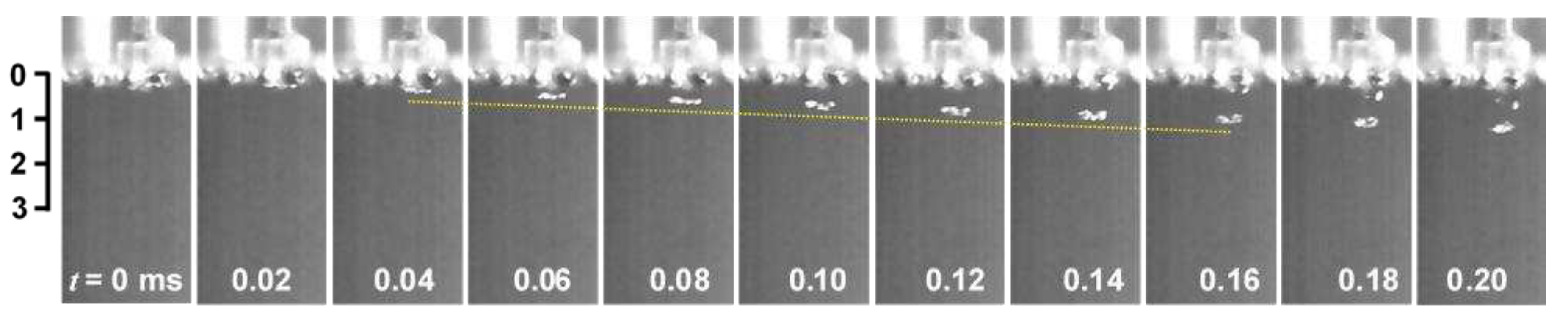
Figure 13 shows the aspect of a vortex cavitation that was injected by the piezo actuator around the submerged water jet. As shown in Figure 13, the water jet was injected vertically downward by the piezo actuator. As shown in Figure 13, a rig vortex cavitation, whose diameter was about 0.6 mm, was observed as a white one as the light source was placed at the same side of the camera. In order to estimate the shedding speed of the ring vortex cavitation, a yellow dotted line was illustrated near the ring vortex cavitation. When the shedding velocity of the ring vortex cavitation was obtained at t = 0.04 ms to 0.16 ms, it was found to be about 5.3 m/s. The aspect of the water jet was determined in order to roughly estimate the jet velocity of the water jet, as shown in Appendix A. The jet velocity was about 5–11 m/s. It was reported that the jet velocity of the high-speed closure of a bioinspired claw reached an asymptotic value in the range of 16 – 17.5 m/s [76]. In addition, the water jet velocity of a snapping claw was found to be 6.5 ± 1.6 m/s [16], and this might be the velocity of the cavitating region with respect to the schematic drawing in the reference of [16]. As such, it can be said that a developed system that uses a piezo actuator can create a ring vortex cavitation by injecting a pulsed water jet in water. However, the volume of the cavitation was found to be considerably smaller than that of the pistol shrimp. One of the reasons for this was that the water jet velocity was not high enough. In addition, the outlet geometry of the nozzle should also be optimized.
4. Conclusions
In order to examine the possibility of developing a novel cavitation generator for mechanical surface treatment, i.e., cavitation peening, a production mechanism for the cavitations caused by a pistol shrimp, i.e., alpheus randalli, was quantitively investigated. As such, two types of cavitation generators were developed. The results obtained can be summarized as follows:
- Pistol shrimps create a cavitation bubble by producing a pulsed water jet, which is generated by the closing of their claws. With respect to the sample pistol shrimp, the volume of the concavo-convex mating area that was required to generate the pulse jet was about 0.35 mm3.
- The size of the cavitation bubble, which was estimated by monitoring the noise, was about 3 mm in diameter, and the volume was 30 times larger than that of the pulsed water jet.
- The required speed for the pulsed water jet to create a cavitation bubble was found to be about 10 m/s.
- The aggressive intensity of the cavitation collapse caused by the pistol shrimp was larger than that of the pulsed laser, even when at an equivalent cavitation volume. This is due to the cushion effect of the pistol shrimp being lesser than that of the pulsed laser.
- The energy efficiency to create a cavitation by a pistol shrimp via a pulsed water jet is about 1,000 times better than that of a pulsed laser.
- A pulsed laser can generate a pulsed water jet, which can thus create cavitations.
- The cavitation generator was realized by using a piezo actuator, which was designed to mimic the mechanism of a pistol shrimp. The ring vortex cavitation around the pulsed water jet was also observed.
Author Contributions
H.S.: conceptualization, methodology, resources, investigation, formal analysis, visualization, project administration, funding acquisition, and writing—original draft. M.T.: investigation, data curation, and visualization. T.T.: conceptualization, data curation, and writing—review and editing. M.Y.: conceptualization, writing—review and editing, and supervision.
Funding
This research was partly supported by JSPS KAKENHI (grant numbers: 23H01292 and 22KK0050).
Institutional Review Board Statement
Not applicable.
Conflicts of Interest
The authors declare no conflicts of interest.
Appendix A
In order to estimate the velocity of a water jet from the developed piezo actuator system, the aspect of the pulsed water jet produced by the piezo actuator was observed, as shown in Figure A1. In Figure A1, the yellow lines of the front edge of the pulsed water jet are illustrated, which can be used to estimate the jet velocity. The velocity of the front edge of the jet was 4.9 m/s for t = 0.02 – 0.12 ms and 11.0 m/s for t = 0.12 – 0.20 ms.
Figure A1.
Aspect of a pulsed water jet that was generated by a piezo actuator.

References
- Brennen, C.E. Cavitation and bubble dynamics, Oxford University Press, 1995.
- Knapp, R.T.; Daily, J.W.; Hammitt, F.G. Cavitation, McGraw-Hill, 1970.
- Versluis, M.; Schmitz, B.; von der Heydt, A.; Lohse, D. How snapping shrimp snap: Through cavitating bubbles. Science 2000, 289, 2114–2117. [Google Scholar] [CrossRef] [PubMed]
- Lohse, D.; Schmitz, B.; Versluis, M. Snapping shrimp make flashing bubbles. nature 2001, 413, 477–478. [Google Scholar] [CrossRef] [PubMed]
- Lillis, A.; Perelman, J.N.; Panyi, A.; Aran Mooney, T. Sound production patterns of big-clawed snapping shrimp (alpheus spp.) are influenced by time-of-day and social context. J Acoust Soc Am 2017, 142, 3311. [Google Scholar] [CrossRef]
- Yang, Y.; Qin, S.; Di, C.; Qin, J.; Wu, D.; Zhao, J. Research on claw motion characteristics and cavitation bubbles of snapping shrimp. Appl Bionics Biomech 2020, 2020, 6585729. [Google Scholar] [CrossRef]
- Larsen, O.N.; Reichmuth, C. Walruses produce intense impulse sounds by clap-induced cavitation during breeding displays. R Soc Open Sci 2021, 8, 210197. [Google Scholar] [CrossRef] [PubMed]
- Song, Z.; Salas, A.K.; Montie, E.W.; Laferriere, A.; Zhang, Y.; Aran Mooney, T. Sound pressure and particle motion components of the snaps produced by two snapping shrimp species (alpheus heterochaelis and alpheus angulosus). J Acoust Soc Am 2021, 150, 3288. [Google Scholar] [CrossRef]
- Kingston, A.C.N.; Woodin, S.A.; Wethey, D.S.; Speiser, D.I. Snapping shrimp have helmets that protect their brains by dampening shock waves. Curr Biol 2022, 32, 3576–3583 e3573. [Google Scholar] [CrossRef] [PubMed]
- Dinh, J.P.; Patek, S.N. Weapon performance and contest assessment strategies of the cavitating snaps in snapping shrimp. Functional Ecology 2022, 37, 327–342. [Google Scholar] [CrossRef]
- Patek, S.N.; Korff, W.L.; Caldwell, R.L. Biomechanics: Deadly strike mechanism of a mantis shrimp - this shrimp packs a punch powerful enough to smash its prey's shell underwater. Nature 2004, 428, 819–820. [Google Scholar] [CrossRef]
- Patek, S.N.; Caldwell, R.L. Extreme impact and cavitation forces of a biological hammer: Strike forces of the peacock mantis shrimp odontodactylus scyllarus. J Exp Biol 2005, 208, 3655–3664. [Google Scholar] [CrossRef] [PubMed]
- Li, X.; Li, X.; Hou, X.; Li, Y.; Meng, Y.; Ma, L.; Tian, Y. Mantis shrimp-inspired underwater striking device generates cavitation. J Bionic Eng 2022, 19, 1758–1770. [Google Scholar] [CrossRef]
- Amini, S.; Tadayon, M.; Chua, J.Q.I.; Miserez, A. Multi-scale structural design and biomechanics of the pistol shrimp snapper claw. Acta Biomater 2018, 73, 449–457. [Google Scholar] [CrossRef] [PubMed]
- Au, W.W.L.; Banks, K. The acoustics of the snapping shrimp synalpheus parneomeris in kaneohe bay. J Acoustical Soc America 1998, 103, 41–47. [Google Scholar] [CrossRef]
- Herberholz, J.; Schmitz, B. Flow visualisation and high speed video analysis of water jets in the snapping shrimp (alpheus heterochaelis). J Comparative Physiology A 1999, 185, 41–49. [Google Scholar] [CrossRef]
- Anker, A.; Ahyong, S.T.; Noël, P.Y.; Palmer, A.R. Morphological phylogeny of alpheid shrimps: Parallel preadaptation and the origin of a key morphological innovation, the snapping claw. Evolution 2006, 60, 2507–2528. [Google Scholar] [CrossRef]
- ASTM G32 (2021), Standard test method for cavitation erosion using vibratory apparatus. ASTM standard 2023, 03.02.
- ASTM G134 (2023), Standard test method for erosion of solid materials by a cavitating liquid jet. ASTM standard 2023, 03.02.
- Soyama, H.; Korsunsky, A.M. A critical comparative review of cavitation peening and other surface peening methods. J Mater Process Technol 2022, 305, 117586. [Google Scholar] [CrossRef]
- Delosrios, E.R.; Walley, A.; Milan, M.T.; Hammersley, G. Fatigue-crack initiation and propagation on shot-peened surfaces in A316 stainless-steel. Int J Fatigue 1995, 17, 493–499. [Google Scholar] [CrossRef]
- Wang, S.P.; Li, Y.J.; Yao, M.; Wang, R.Z. Compressive residual stress introduced by shot peening. J Mater Process Technol 1998, 73, 64–73. [Google Scholar] [CrossRef]
- Wagner, L. Mechanical surface treatments on titanium, aluminum and magnesium alloys. Mater Sci Eng A 1999, 263, 210–216. [Google Scholar] [CrossRef]
- Torres, M.A.S.; Voorwald, H.J.C. An evaluation of shot peening, residual stress and stress relaxation on the fatigue life of AISI 4340 steel. Int J Fatigue 2002, 24, 877–886. [Google Scholar] [CrossRef]
- McClung, R.C. A literature survey on the stability and significance of residual stresses during fatigue. Fatigue Fract Eng Mater Struct 2007, 30, 173–205. [Google Scholar] [CrossRef]
- Harada, Y.; Fukauara, K.; Kohamada, S. Effects of microshot peening on surface characteristics of high-speed tool steel. J Mater Process Technol 2008, 201, 319–324. [Google Scholar] [CrossRef]
- John, M.; Kalvala, P.R.; Misra, M.; Menezes, P.L. Peening techniques for surface modification: Processes, properties, and applications. Materials 2021, 14, 3841. [Google Scholar] [CrossRef] [PubMed]
- Kikuchi, S.; Minamizawa, K.; Arakawa, J.; Akebono, H.; Takesue, S.; Hayakawa, M. Combined effect of surface morphology and residual stress induced by fine particle and shot peening on the fatigue limit for carburized steels. Int J Fatigue 2023, 168, 107441. [Google Scholar] [CrossRef]
- Bagherifard, S.; Guagliano, M. Fatigue behavior of a low-alloy steel with nanostructured surface obtained by severe shot peening. Eng Fract Mech 2012, 81, 56–68. [Google Scholar] [CrossRef]
- Bagherifard, S.; Beretta, N.; Monti, S.; Riccio, M.; Bandini, M.; Guagliano, M. On the fatigue strength enhancement of additive manufactured AlSi10Mg parts by mechanical and thermal post-processing. Mater Des 2018, 145, 28–41. [Google Scholar] [CrossRef]
- Bag, A.; Delbergue, D.; Ajaja, J.; Bocher, P.; Levesque, M.; Brochu, M. Effect of different shot peening conditions on the fatigue life of 300 M steel submitted to high stress amplitudes. Int. J. Fatigue 2020, 130, 105274. [Google Scholar] [CrossRef]
- Kumar, C.S.; Chattopadhyay, K.; Singh, V.; Mahobia, G.S. Enhancement of low-cycle fatigue life of high-nitrogen austenitic stainless steel at low strain amplitude through ultrasonic shot peening. Mater Today Commun 2020, 25, 101576. [Google Scholar] [CrossRef]
- Maleki, E.; Bagherifard, S.; Bandini, M.; Guagliano, M. Surface post-treatments for metal additive manufacturing: Progress, challenges, and opportunities. Addit Manuf 2021, 37, 101619. [Google Scholar] [CrossRef]
- Miao, H.Y.; Demers, D.; Larose, S.; Perron, C.; Levesque, M. Experimental study of shot peening and stress peen forming. J Mater Process Technol 2010, 210, 2089–2102. [Google Scholar] [CrossRef]
- Bagherifard, S.; Ghelichi, R.; Guagliano, M. Numerical and experimental analysis of surface roughness generated by shot peening. Appl Surf Sci 2012, 258, 6831–6840. [Google Scholar] [CrossRef]
- Soyama, H. Comparison between the improvements made to the fatigue strength of stainless steel by cavitation peening, water jet peening, shot peening and laser peening. J Mater Process Technol 2019, 269, 65–78. [Google Scholar] [CrossRef]
- Zhou, J.; Retraint, D.; Sun, Z.; Kanoute, P. Comparative study of the effects of surface mechanical attrition treatment and conventional shot peening on low cycle fatigue of A 316L stainless steel. Surf Coat Technol 2018, 349, 556–566. [Google Scholar] [CrossRef]
- Soyama, H.; Chighizola, C.R.; Hill, M.R. Effect of compressive residual stress introduced by cavitation peening and shot peening on the improvement of fatigue strength of stainless steel. J Mater Process Technol 2021, 288, 116877. [Google Scholar] [CrossRef]
- Kumagai, M.; Curd, M.E.; Soyama, H.; Ungár, T.; Ribárik, G.; Withers, P.J. Depth-profiling of residual stress and microstructure for austenitic stainless steel surface treated by cavitation, shot and laser peening. Mater Sci Eng A 2021, 813, 141037. [Google Scholar] [CrossRef]
- Langdon, G.S.; Schleyer, G.K. Unusual strain rate sensitive behaviour of AISI 316L austenitic stainless steel. J. Strain Anal. Eng. Des. 2004, 39, 71–86. [Google Scholar] [CrossRef]
- Clarke, K.D.; Comstock, R.J.; Mataya, M.C.; van Tyne, C.J.; Matlock, D.K. Effect of strain rate on the yield stress of ferritic stainless steels. Metallurgical and Materials Trans A 2008, 39, 752–762. [Google Scholar] [CrossRef]
- Jiao, Y.F.; Hou, Y.L. Dynamic mechanical properties of austenitic 304L stainless steel with different strain rates. Functional Materials 2020, 27, 93–99. [Google Scholar]
- Husain, A.; La, P.; Hongzheng, Y.; Jie, S. Molecular dynamics as a means to investigate grain size and strain rate effect on plastic deformation of 316 L nanocrystalline stainless-steel. Materials 2020, 13, 3223. [Google Scholar] [CrossRef] [PubMed]
- Soyama, H. Cavitating jet: A review. Appl Sci 2020, 10, 7280. [Google Scholar] [CrossRef]
- Soyama, H. Luminescence intensity of vortex cavitation in a venturi tube changing with cavitation number. Ultrason. Sonochem. 2021, 71, 105389. [Google Scholar] [CrossRef] [PubMed]
- Kawanami, Y.; Kato, H.; Yamaguchi, H.; Maeda, M.; Nakasumi, S. Inner structure of cloud cavity on a foil section. JSME Inter J 2002, 45B, 655–661. [Google Scholar] [CrossRef]
- Dular, M.; Petkovšek, M. On the mechanisms of cavitation erosion – coupling high speed videos to damage patterns. Exp Therm Fluid Sci 2015, 68, 359–370. [Google Scholar] [CrossRef]
- Soyama, H.; Iga, Y. Laser cavitation peening: A review. Appl Sci 2023, 13, 6702. [Google Scholar] [CrossRef]
- Soyama, H. Laser cavitation peening and its application for improving the fatigue strength of welded parts. Metals 2021, 11, 531. [Google Scholar] [CrossRef]
- Gu, J.Y.; Luo, C.H.; Ma, P.C.A.; Xu, X.C.; Wu, Y.; Ren, X.D. Study on processing and strengthening mechanisms of mild steel subjected to laser cavitation peening. Appl Surf Sci 2021, 562, 150242. [Google Scholar] [CrossRef]
- Soyama, H.; Kuji, C.; Liao, Y. Comparison of the effects of submerged laser peening, cavitation peening and shot peening on the improvement of the fatigue strength of magnesium alloy AZ31. J Magnesium Alloys 2023, 11, 1592–1607. [Google Scholar] [CrossRef]
- Peyre, P.; Fabbro, R.; Merrien, P.; Lieurade, H.P. Laser shock processing of aluminium alloys. Application to high cycle fatigue behaviour. Mater Sci Eng A 1996, 210, 102–113. [Google Scholar] [CrossRef]
- Hatamleh, O.; Lyons, J.; Forman, R. Laser and shot peening effects on fatigue crack growth in friction stir welded 7075-T7351 aluminum alloy joints. Int J Fatigue 2007, 29, 421–434. [Google Scholar] [CrossRef]
- Telang, A.; Gnaupel-Herold, T.; Gill, A.; Vasudevan, V.K. Effect of applied stress and temperature on residual stresses induced by peening surface treatments in alloy 600. J Mater Eng Perform 2018, 27, 2796–2804. [Google Scholar] [CrossRef]
- Mao, B.; Liao, Y.L.; Li, L. Abnormal twin-twin interaction in an Mg-3Al-1Zn magnesium alloy processed by laser shock peening. Scr Mater 2019, 165, 89–93. [Google Scholar] [CrossRef]
- Yang, F.; Liu, P.; Zhou, L.; He, W.; Pan, X.; An, Z. Review on anti-fatigue performance of gradient microstructures in metallic components by laser shock peening. Metals 2023, 13, 979. [Google Scholar] [CrossRef]
- Li, Y.; Geng, J.; Wang, Z.; Shao, Z.; Zhang, C.; Chen, D.; Wang, H. Thermal evolutions of residual stress and strain hardening of GH4169 Ni-based superalloy treated by laser shock peening. Surf Coat Tech 2023, 467, 129690. [Google Scholar] [CrossRef]
- Ye, Y.; Zhang, Y.; Huang, T.; Zou, S.; Dong, Y.; Ding, H.; Vasudevan, V.K.; Ye, C. A critical review of laser shock peening of aircraft engine components. Adv Eng Mater 2023, 2201451. [Google Scholar] [CrossRef]
- Sano, Y.; Obata, M.; Kubo, T.; Mukai, N.; Yoda, M.; Masaki, K.; Ochi, Y. Retardation of crack initiation and growth in austenitic stainless steels by laser peening without protective coating. Mater Sci Eng A 2006, 417, 334–340. [Google Scholar] [CrossRef]
- Yoda, M.; Chida, I.; Okada, S.; Ochiai, M.; Sano, Y.; Mukai, N.; Komotori, G.; Saeki, R.; Takagi, T.; Sugihara, M.; Yoriki, H. Development and application of laser peening system for PWR power plants. Proc 14th Inter Conf Nuclear Eng 2006, 419–424. [Google Scholar]
- Sano, Y. Quarter century development of laser peening without coating. Metals 2020, 10, 152. [Google Scholar] [CrossRef]
- Sano, Y.; Akita, K.; Sano, T. A mechanism for inducing compressive residual stresses on a surface by laser peening without coating. Metals 2020, 10, 816. [Google Scholar] [CrossRef]
- Kaufman, J.; Špirit, Z.; Vasudevan, V.K.; Steiner, M.A.; Mannava, S.R.; Brajer, J.; Pína, L.; Mocek, T. Effect of laser shock peening parameters on residual stresses and corrosion fatigue of AA5083. Metals 2021, 11, 1635. [Google Scholar] [CrossRef]
- Sasoh, A.; Watanabe, K.; Sano, Y.; Mukai, N. Behavior of bubbles induced by the interaction of a laser pulse with a metal plate in water. Appl Phy A 2005, 80, 1497–1500. [Google Scholar] [CrossRef]
- Soyama, H.; Sekine, Y.; Saito, K. Evaluation of the enhanced cavitation impact energy using a PVDF transducer with an acrylic resin backing. Measurement 2011, 44, 1279–1283. [Google Scholar] [CrossRef]
- Soyama, H. Key factors and applications of cavitation peening. Inter J Peen Sci Technol 2017, 1, 3–60. [Google Scholar]
- Sano, Y.; Kato, T.; Mizuta, Y.; Tamaki, S.; Yokofujita, K.; Taira, T.; Hosokai, T.; Sakino, Y. Development of a portable laser peening device and its effect on the fatigue properties of HT780 butt-welded joints. Forces in Mechanics 2022, 7, 100080. [Google Scholar] [CrossRef]
- Takahashi, N.; Kugimiya, T.; Seki, T.; Terao, K.; Kunoh, T.; Mizuno, M. Application of ultrasonic cavitation to metal working and surface-treatment of mild-steel. JSME Inter J 1987, 30, 1229–1236. [Google Scholar] [CrossRef]
- Rawers, J.C.; McCune, R.A.; Dunning, J.S. Ultrasound treatment of centrifugally atomized 316 stainless steel powders. Metallurgical Transactions A 1991, 22A, 3025–3033. [Google Scholar] [CrossRef]
- Nakagawa, M.; Watanabe, T. Introducing compressive residual stress on metal surfaces by irradiating ultrasonic wave with a horn in water : Surface modification by irradiating ultrasonic wave in liquid (report 1). Quarterly Journal of Japan Welding Society 2004, 22, 587–594. [Google Scholar]
- Toh, C.K. The use of ultrasonic cavitation peening to improve micro-burr-free surfaces. Int J Adv Manuf Technol 2007, 31, 688–693. [Google Scholar] [CrossRef]
- Gao, Y.B.; Wu, B.X.; Liu, Z.; Zhou, Y.; Shen, N.G.; Ding, H.T. Ultrasonic cavitation peening of stainless steel and nickel alloy. J Manuf Sci Eng 2014, 136, 014502. [Google Scholar] [CrossRef]
- Okada, T.; Iwai, Y.; Hattori, S.; Tanimura, N. Relation between impact load and the damage produced by cavitation bubble collapse. Wear 1995, 184, 231–239. [Google Scholar] [CrossRef]
- Koukouvinis, P.; Bruecker, C.; Gavaises, M. Unveiling the physical mechanism behind pistol shrimp cavitation. Sci Rep 2017, 7, 13994. [Google Scholar] [CrossRef] [PubMed]
- Yin, H.; Zhang, C.; Xu, Y.; Heng, J. Structural design and jet-cavitation mechanism of bioinspired snapping-claw apparatus. J Vibration Eng Technol 2021, 10, 649–666. [Google Scholar] [CrossRef]
- Salinas-Vázquez, M.; Godínez, F.A.; Vicente, W.; Guzmán, J.E.V.; Valdés, R.; Palacios-Morales, C.A. Numerical simulation of a flow induced by the high-speed closure of a bioinspired claw. J Fluids Structures 2022, 113, 103654. [Google Scholar] [CrossRef]
- Tang, X.; Staack, D. Bioinspired mechanical device generates plasma in water via cavitation. Science Advances 2019, 5, eaau7765. [Google Scholar] [CrossRef] [PubMed]
- Tajima, K.; Yagi, K.; Mori, Y. Development of an impulsive motion generator inspired by cocking slip joint of snapping shrimp. Bioinspir Biomim 2023, 18, 066002. [Google Scholar] [CrossRef] [PubMed]
- Rayleigh, L. On the pressure developed in a liquid during the collapse of a spherical cavity. The London, Edinburgh, and Dublin Philosophical Magazine and Journal of Science 1917, 34, 94–98. [Google Scholar] [CrossRef]
- Soyama, H. Effect of nozzle geometry on a standard cavitation erosion test using a cavitating jet. Wear 2013, 297, 895–902. [Google Scholar] [CrossRef]
- Ohl, C.D.; Lindau, O.; Lauterborn, W. Luminescence from spherically and aspherically collapsing laser induced bubbles. Phys Rev Lett 1998, 80, 393–396. [Google Scholar] [CrossRef]
Figure 1.
Pistol shrimp (Alpheus randalli).
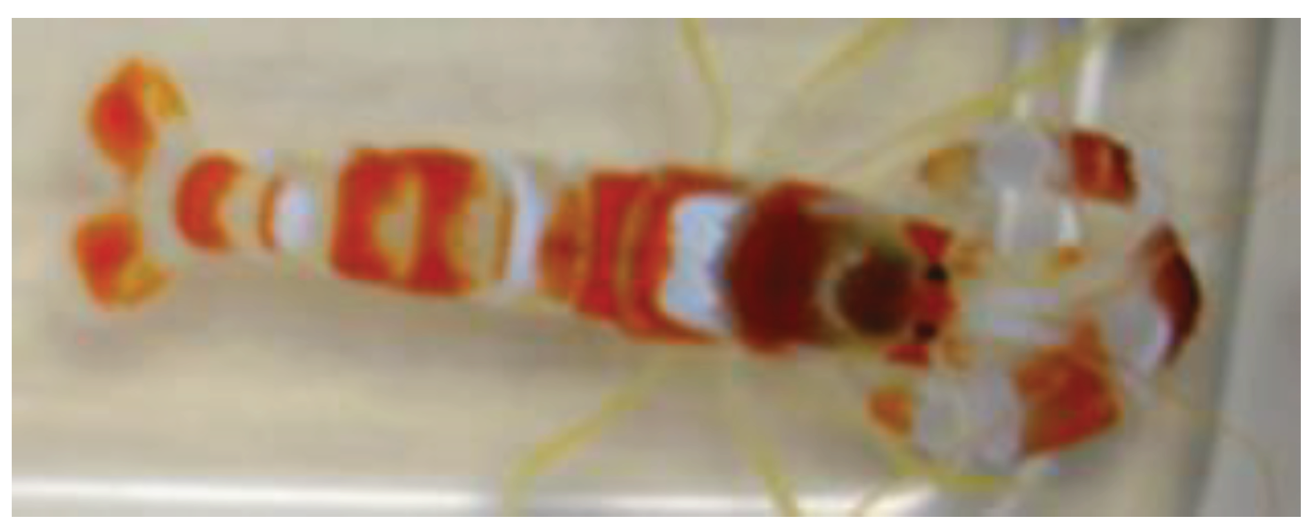
Figure 2.
Claw of the pistol shrimp.
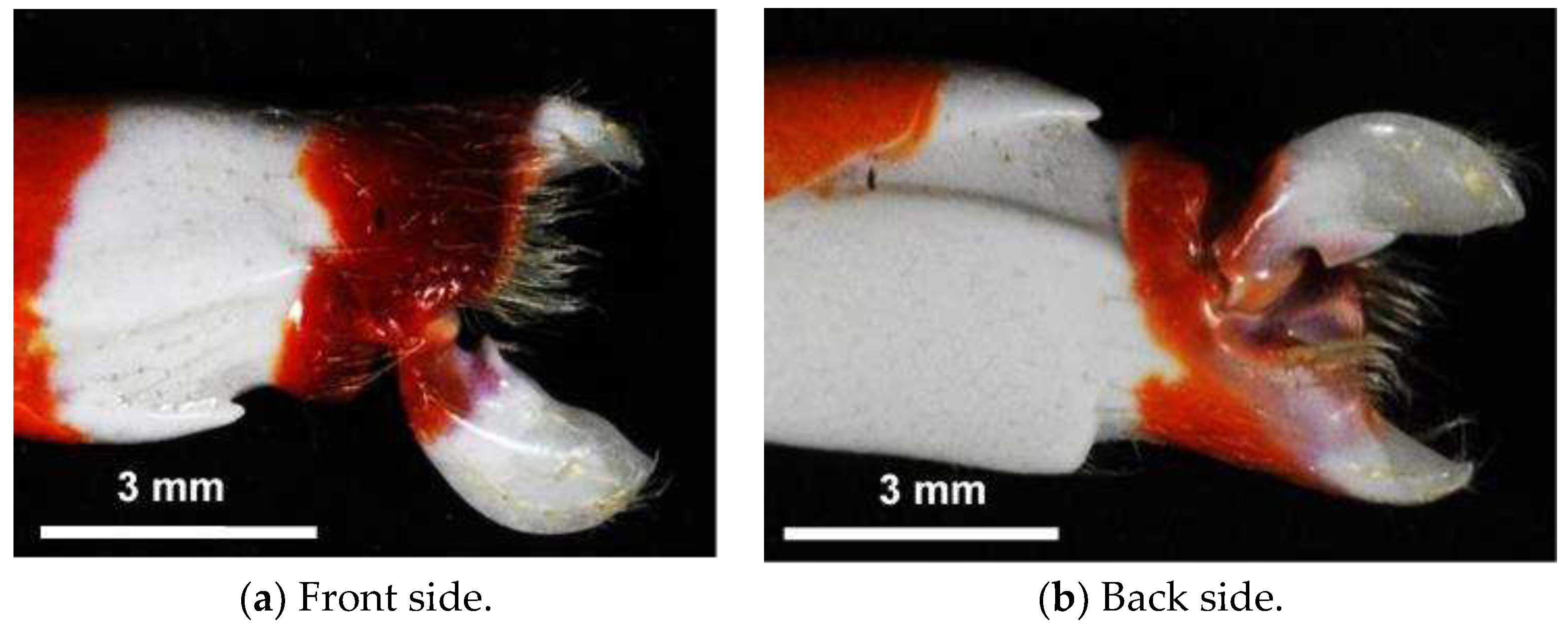
Figure 3.
Schematics of the measurement of noise induced by the pistol shrimp (all of the dimensions are in mm).
Figure 3.
Schematics of the measurement of noise induced by the pistol shrimp (all of the dimensions are in mm).
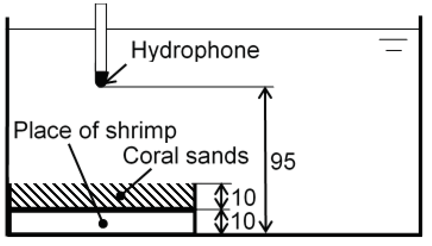
Figure 4.
Top view of a pulsed laser system (λ = 532 nm).
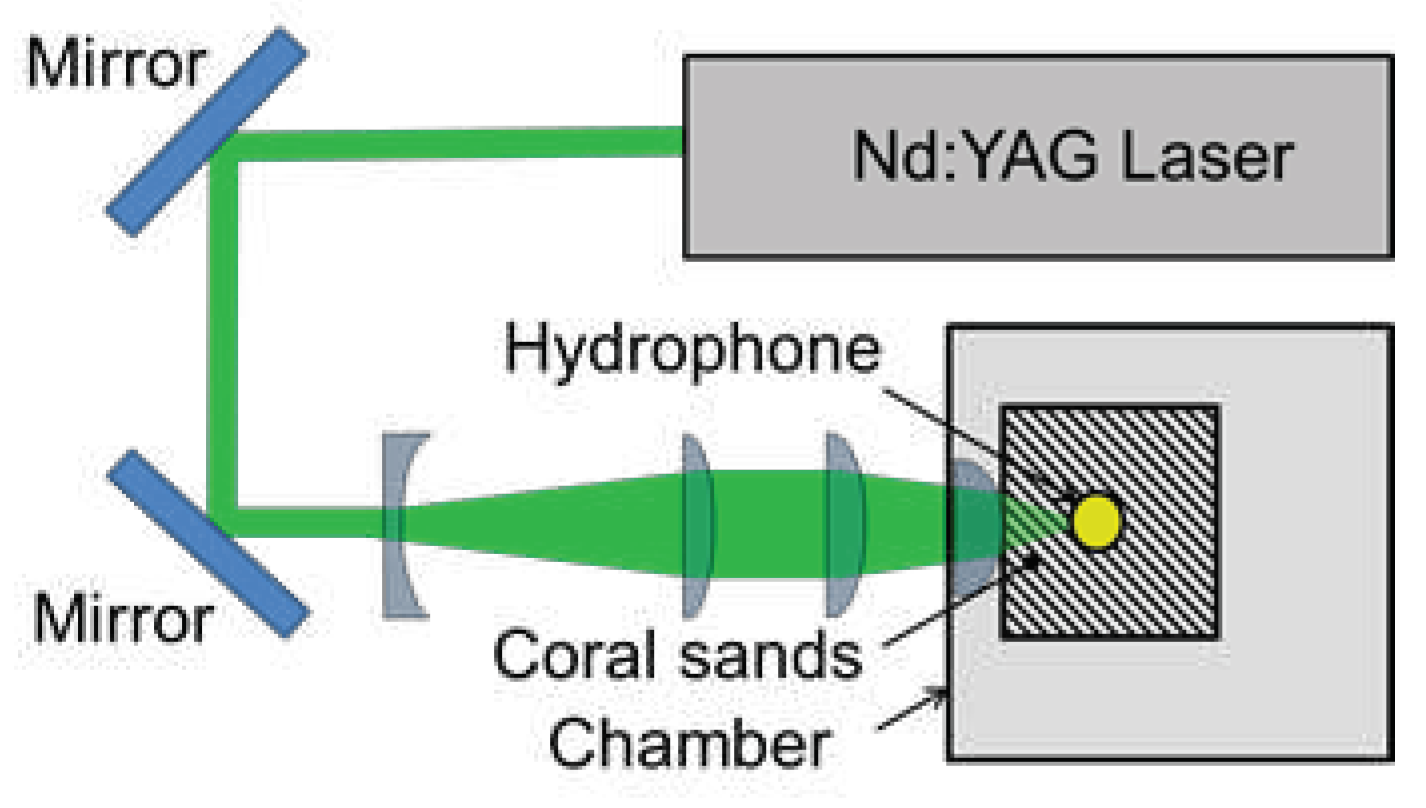
Figure 5.
Schematic diagram of a cavitation generator that uses a pulsed laser (λ = 1,064 nm).
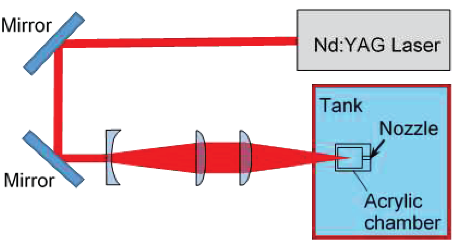
Figure 6.
A cavitation generator that uses a piezo actuator.
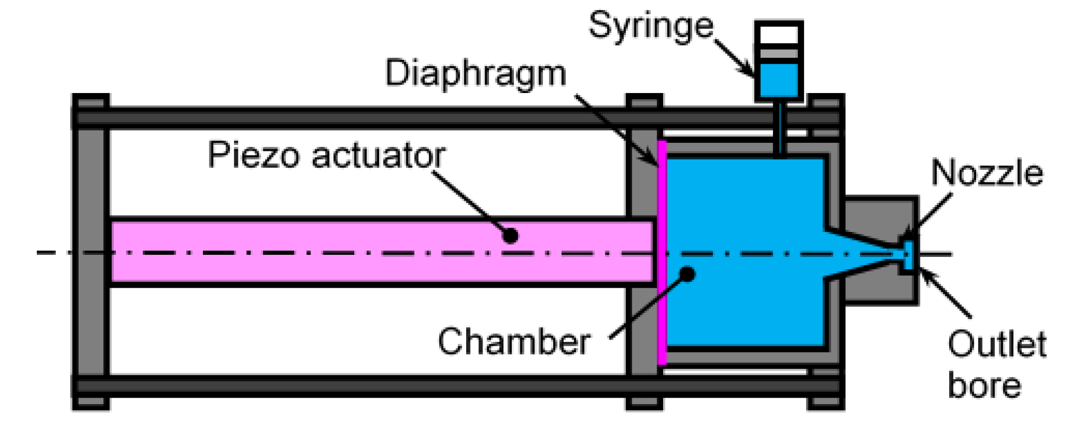
Figure 7.
An μCT image of an opened claw.
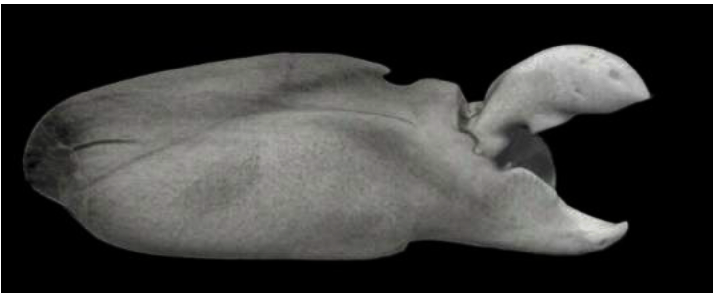
Figure 8.
Cross-section image of a closed claw that was observed by μCT.
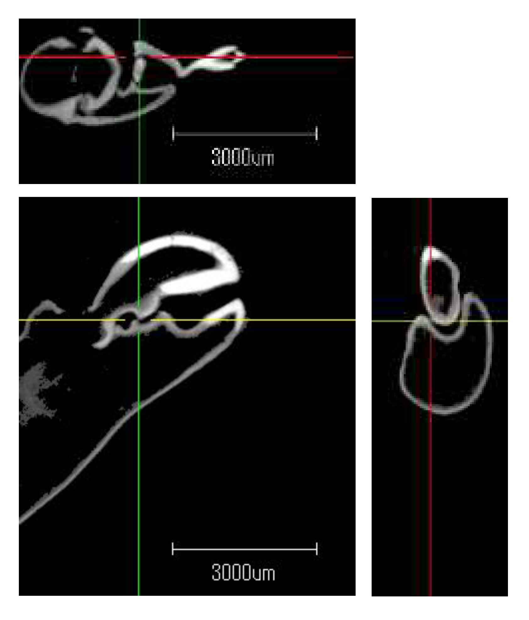
Figure 9.
Noise induced by the pistol shrimp and pulsed laser.
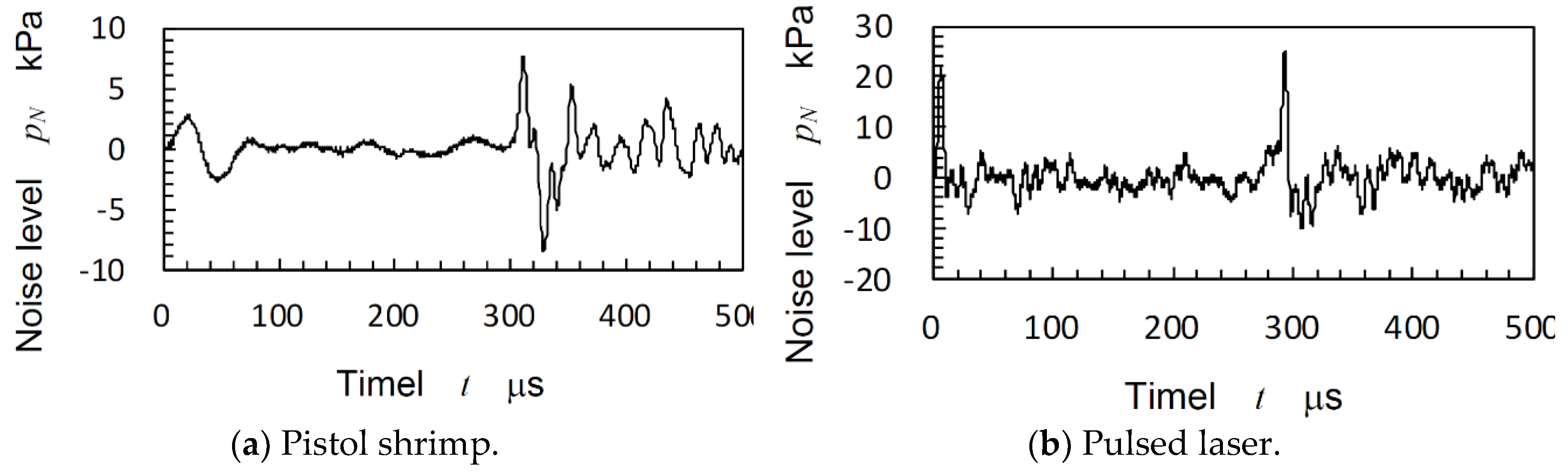
Figure 10.
Relation between the developing time and maximum diameter of the laser cavitation.
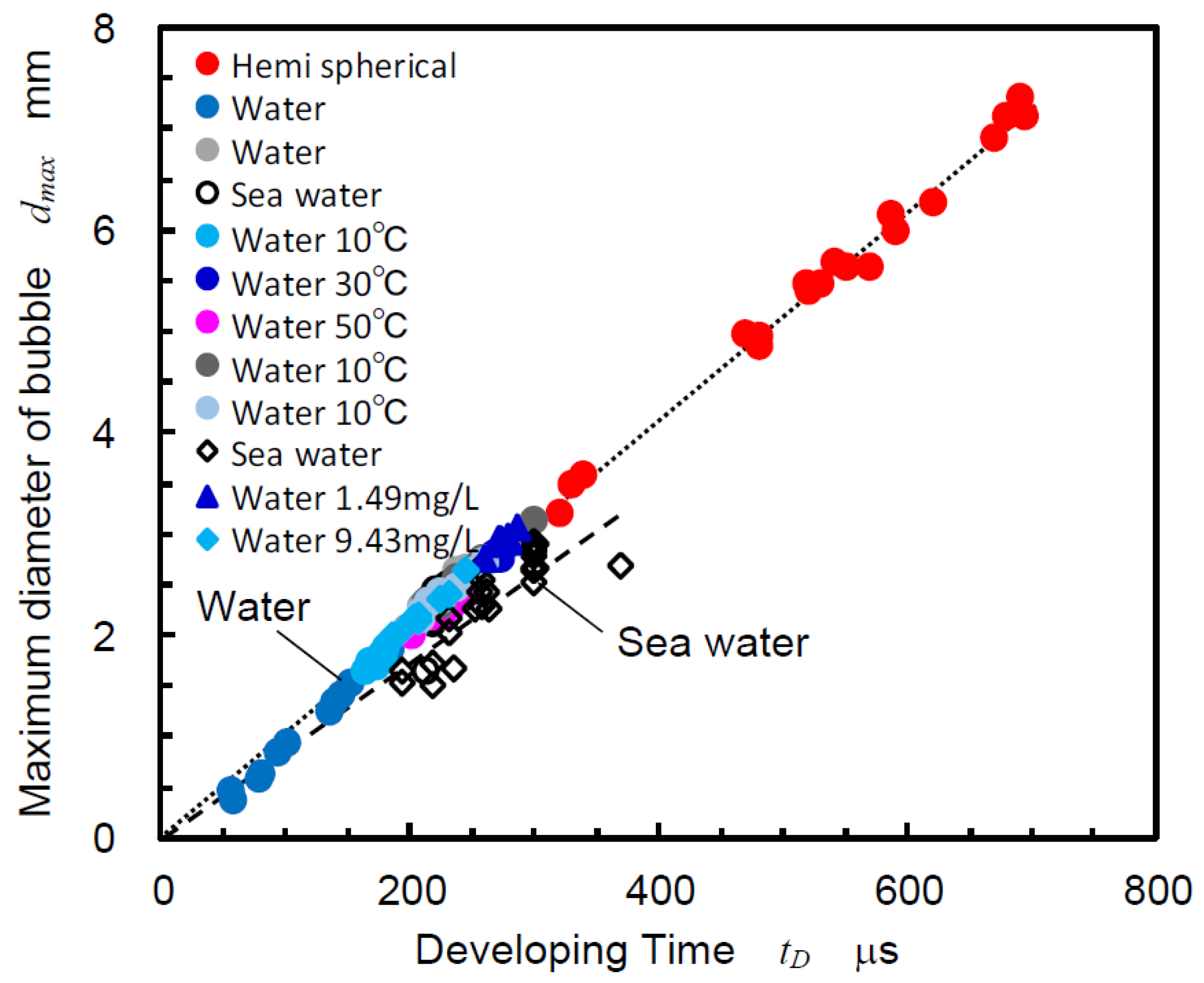
Figure 11.
Comparison of the noise level at bubble collapse between the shrimp and pulsed laser.
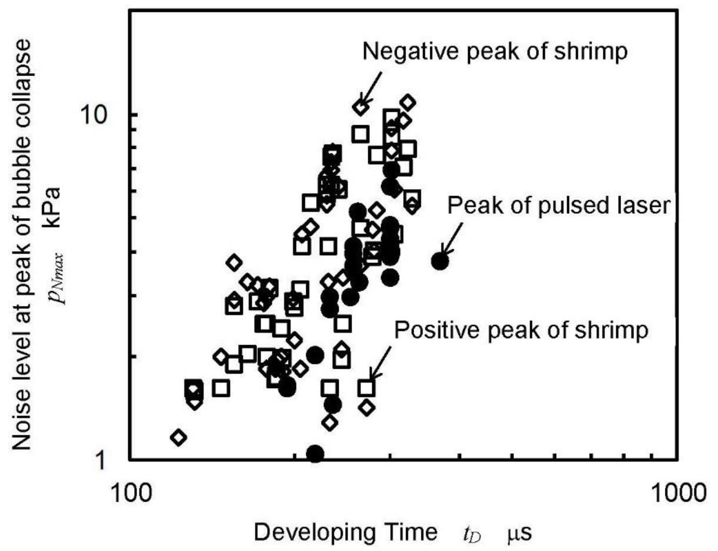
Figure 12.
Aspect of the cavitation induced by submerged pulsed water jets using pulsed lasers.
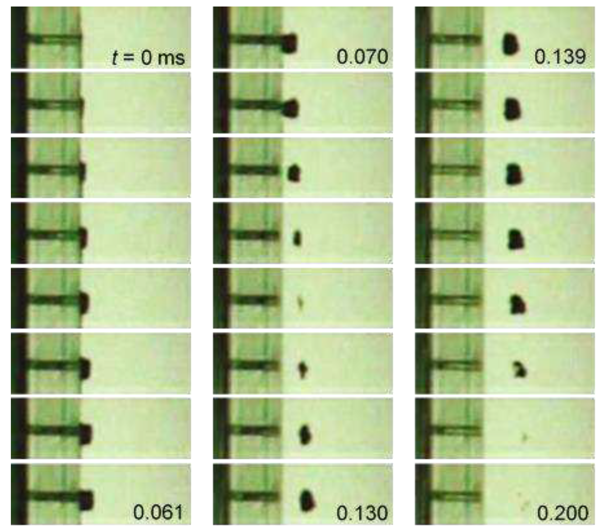
Figure 13.
Aspect of the cavitation induced by a submerged pulse water jet using a piezo actuator.
Disclaimer/Publisher’s Note: The statements, opinions and data contained in all publications are solely those of the individual author(s) and contributor(s) and not of MDPI and/or the editor(s). MDPI and/or the editor(s) disclaim responsibility for any injury to people or property resulting from any ideas, methods, instructions or products referred to in the content. |
© 2023 by the authors. Licensee MDPI, Basel, Switzerland. This article is an open access article distributed under the terms and conditions of the Creative Commons Attribution (CC BY) license (http://creativecommons.org/licenses/by/4.0/).
Copyright: This open access article is published under a Creative Commons CC BY 4.0 license, which permit the free download, distribution, and reuse, provided that the author and preprint are cited in any reuse.


