Submitted:
15 November 2023
Posted:
16 November 2023
Read the latest preprint version here
Abstract
In order to improve the stiffness of the flexible robot,this paper proposes a variable-stiffness elastic actuator to improve the rigidity of flexible robots. The actuator integrates the working principles of a pneumatic drive, wedge structure, and particle blockage. the tensile stiffness of the actuator is nonlinearly negatively correlated with the air pressure because of the structural and material properties.The compressive stiffness and lateral stiffness increases nonlinearly as air pressure increases, being 3and 121 times greater at 0.17 MPa compared to 0 MPa, respectively. Beyond 0.17 MPa, the two stiffness of the actuator experiences incremental growth due to wedge impedance forces.
Keywords:
variable-stiffness
; pneumatic actuation
; elastic actuator
; flexible robot
1. Introduction
Flexible robots have broad application prospects in the field of service robots because of their driving flexibility, unstructured environmental adaptability and human-computer interaction security. Researchers have conducted in-depth research on flexible robots, making full use of elastic or soft materials to achieve flexibility, and unstructured environmental adaptability of flexible robots. However, the traditional flexible robot has low stiffness and weak bearing capacity, which limits the application of flexible robot to a certain extent.
In order to improve the stiffness of flexible robots, researchers have proposed variable-stiffness technology. variable-stiffness structure is introduced into the design of flexible robots to improve their stiffness and bearing capacity and expand their application range. At present, the common variable-stiffness technologies include particle blocking, structural interference and variable-stiffness materials.The particle blocking variable-stiffness technology developed in the early stage is mostly realized by vacuum negative pressure. The most typical case is the particle blocking variable-stiffness gripper designed by Amend et al. The outer side of the gripper is a film made of soft material, and the inner part is filled with particles in the flow state. Therefore, the inclusion of the clamping object is relatively strong, and the shape can be adjusted independently to adapt to various objects. HUA proposes a flexible variable-stiffness manipulator, which uses the negative pressure extraction method to achieve particle blockage. The bending angle is 86 °, and the maximum grasping force is 11.89 N. Li developed a piston-type particle blocking variable-stiffness manipulator claw. The outer membrane is filled with particles, and the piston pushes the particles to achieve the blocking state. The bending deformation and variable-stiffness function of the manipulator claw are realized by controlling the particle filling volume and the piston driving force.Hiroya 's team proposed an electrostatic layer adsorption layered interference variable-stiffness technology, which increases the adsorption force of the thin layer through the change of the electric field to increase the stiffness. Giannaccini 's team also developed an antagonistic variable-stiffness flexible arm based on the antagonistic principle. The pressure gradient of the three groups of contracted artificial muscles is used to realize the spatial bending deformation of the flexible arm, and the pressure of the elongated artificial muscle is applied to realize the stiffness change . Wang developed a three-finger flexible gripper using shape memory polymer. The finger has strong fluidity at high temperature and can adapt to various shape objects. After grasping the object, it is treated at low temperature to improve the stiffness of the gripper. The stiffness of the gripper can be increased by 54 times by adjusting the temperature.
In summary, the variable-stiffness technology has a large range of stiffness changes, but the bearing capacity is still insufficient. In this paper, a variable-stiffness elastic actuator is proposed by combining the working principle of pneumatic drive, wedge structure and particle blocking. It has the advantages of on-line adjustment of stiffness, large range of variable-stiffness, compact structure and fast response. It solves the problem of insufficient stiffness and weak bearing capacity of pneumatic flexible arm, and improves the posture retention ability of flexible arm.
2. Theory and Design
The variable-stiffness elastic actuator is composed of multiple components arranged coaxially, comprising a pressurized airbag, filling particles, a constrained airbag, and a constrained spiral tube, as illustrated in Figure 1. The core components are installed coaxially. A stepped sealing plug is situated above the pressurized airbag and anchored to the upper-end cover to ensure an airtight seal. A through-hole in the middle of the lower sealing plug connects to a pneumatic joint, serving as the inlet for pressurized gas. When subjected to air pressure, the pressurized airbag initially undergoes radial expansion due to its inherent structural and material properties. Axial elongation occurs after the radial deformation reaches its limits. Filling particles are placed between the pressurized and constrained airbag, mainly to facilitate the ’ return to their initial positions after depressurization. At the same time, deformation between the constrained and the pressurized airbags ensures even distribution of the filling particles during the actuator's elongation. The constrained spiral tubes are interlocking, allowing for elongation, compression, and bending movements. These tubes fully constrain the internal airbag, preventing any instability. The extent of their elongation determines both the elongation and bending angle of the variable-stiffness elastic actuator. As the spiral tube elongates or bends, the volume of the inner wall grooves in the nested structure varies in tandem with these changes.
The variable-stiffness principle underlying the actuator is depicted in Figure 2. In its initial state (Figure 2a), the pressurized airbag is unpressurized, allowing the filling particles to flow dynamically, and the groove in the spiral tube is half open. When the variable-stiffness elastic actuator is pressurized, the filling particles are squeezed into blocked state, and the groove enlarges as the actuator elongates axially.The filling particles and constrained airbag become embedded in this expanded groove to form a wedge structure. At this time, the axial force is applied to the actuator, as illustrated in Figure 2b, when the axial force is pressed down to the actuator, the reason for the change in the stiffness includes blocked particle and wedge impedance force. When the axial force is pulled up the actuator,there’s no wedge impedance force, so the variable-stiffness principle is only based on particle blockage. When the lateral force is applied to the actuator, as shown in Figure 2c, the wedge structure on the tension side of the constraint spiral tube does not produce impedance force, and the wedge impedance force exists on the compression side. The reason for the change in the stiffness includes blocked particle and the wedge impedance force on the compression side of the spiral tube.
3. Theoretical modeling
The variable-stiffness elastic actuator is applied to the flexible arm as a driving device and realize the variable-stiffness function of the flexible arm at the same time. During the movement of the flexible arm, the actuator mainly bears axial force and lateral force. Therefore, the anti-tensile, anti-compressive and lateral stiffness are mainly studied.
3.1. Anti-tensile stiffness at any position of variable-stiffness elastic actuator
As illustrated in Figure 3, the actuator undergo axial elongation due to applied air pressure. In this state, a axial force Fz is applied at the center of the upper-end cover, causing the actuator to elongate and deform As a result, the center point of the upper-end cover moves along the axis direction. The internal friction contributing to the impedance moment mainly includes frictional interactions in various regions: between the constrained airbag and the spiral tube, among the filling particles and the constrained airbag, and finally, between the filling particles and pressurized airbag. The constrained airbag , pressurized airbag and spiral tube generate deformation impedance force.
The static equilibrium equation of the variable-stiffness elastic actuator is as follows:
In the formula, is the driving force, is the friction impedance forces between the constrained airbag and the constrained spiral tube, between the filling particles, between the filling particles and the constrained airbag, and between the filling particles and the pressurized airbag, is the axial deformation impedance force of constrained airbag, pressurized airbag and constrained spiral tube.
- Driving force
The driving force is given by:
where represents the air pressure applied to the pressurized airbag, denotes the cross-sectional area of the cavity after the pressurized airbag has deformed.
Both the constrained and pressurized airbags are fabricated from silicon-fluorine rubber—a highly elastic and incompressible material—ensuring that the annular volume remains constant after deformation. The constrained spiral tube is made of a rigid material, so its internal cross-sectional area remains unchanged before and after deformation. Consequently, any volume change in the inner cavity of the constrained spiral tube directly reflects the volume change in the inner cavity of the pressurized airbag.
where represents the cross-sectional area of the inner wall of the spiral tube. denotes the initial effective length of the variable-stiffness elastic actuator. symbolizes the initial cross-sectional area of the cavity in the pressurized airbag.
where stands for the diameter of the inner wall of the spiral tube.
where represents the initial diameter of the inner wall of the pressurized airbag.
The effective working area of the pressurized airbag is defined by the cross-sectional area of its cavity.
Substituting Equation (6) into Equation (2), the driving force is
- 2.
- Friction impedance Force
As the actuator expands under pressure, a positive pressure is generated on the inner wall surface of the pressurized airbag, generating a friction impedance force among the actuator's components. (Figure 4).
Where, is the pressure on the micro-unit inner wall surface of the pressurized airbag, represents the area of the micro-unit side after the airbag is pressurized and deformed. represents the annular angle of the micro-unit on the inner wall surface. denotes the height of the micro-unit on the inner wall surface.
The friction force between the constrained airbag and the spiral tube is:
Where is the friction coefficient between the constrained airbag and spiral tube,
The axial friction force among the filling particles is
Where, signifies the friction coefficient between the particles, denotes the particle correction coefficient,
The friction force among the constrained airbag and particles is
Where, is the friction coefficient between particles and constrained airbag.
The friction between particles and pressurized airbag is
Where, is the friction coefficient between particles and pressurized airbag.
- 3.
- Deformation impedance force
The variable-stiffness elastic actuator moves ∆L axial elongation under the action of external force Fz. According to the principle of elastic deformation [18], the axial deformation impedance force of the constrained airbag is
where denotes the elastic modulus of the airbag, stands for the annular cross-sectional area after deformation of the constrained airbag
The annular volume remains unchanged before and after the deformation of the pressurized airbag.
Where, is the initial diameter of the outer wall of the constrained airbag, is the initial diameter of the inner wall of the constrained airbag.
The axial deformation impedance force of the constrained airbag under the action of air pressure Pa and external force Fz is obtained by combining Equations (13) and (14).
The axial deformation impedance force of the pressurized airbag is
Where, stands for the annular cross-sectional area after deformation of the airbag, denotes the initial outer diameter of pressurized airbag, is the initial diameter of the inner wall of pressurized airbag.
The impedance force generated of the constrained spiral tube is smaller than the above force and can be ignored. Therefore, the axial elongation of the variable-stiffness elastic actuator under the action of Fz is
The anti-tensile stiffness of the variable-stiffness elastic actuator is
When , the anti-tensile stiffness is calculated according to Equation (18). When , the variable-stiffness elastic actuator reaches the maximum elongation, and the anti-tensile stiffness depends on the anti-tensile strength of constrained spiral tube.
3.2. Anti-compressive stiffness at any position of variable-stiffness elastic actuator
As illustrated in Figure 5, the actuator undergo axial elongation due to applied air pressure. In this state, a axial force F-z is applied at the center of the upper-end cover, causing the actuator to elongate and deform As a result, the center point of the upper-end cover moves along the axis direction. At this time, the internal friction contributing to the impedance moment mainly includes frictional interactions in various regions: between the constrained airbag and the spiral tube, among the filling particles and the constrained airbag, and finally, between the filling particles and pressurized airbag. The constrained airbag , pressurized airbag and spiral tube generate deformation impedance force. The wedge impedance force Fj is generated by filling particles and constrained airbag in the spiral groove.
According to the static equilibrium equation,
- Driving Force
The variable-stiffness elastic actuator is compressed under the action of external force, and the air pressure value remains unchanged. Therefore, when the elongation changes to , the cross-sectional area of the inner cavity changes. According to Equation (7),
- 2.
- Friction impedance force
The friction force between constrained airbag and spiral tube is constrained to be
The axial friction force among the filling particles is
The friction force among particles and constrained airbag is equal to
The friction between particles and pressurized airbag is
- 3.
- Deformation impedance force
According to the Equation (15), the deformation impedance of constrained airbag is obtained as
According to the Equation (16), the deformation impedance of pressurized airbag is
- 4.
- Wedge impedance moment
The magnitude of the wedge resistance force is influenced by the volume of the filler particles and the depth to which the constrained airbag is embedded in groove. When the embedded depth of the filled particles is less than the radius of the particles (Figure 6a), the force model can be analyzed using wedge clamping mechanisms, as depicted in Figure 6d. When the filling particles are completely embedded in the groove (Figure 6b), the force model is as shown in Figure 6e. Essentially, the force magnitude depends on the anti-compressive strength of the embedded particles and the constrained airbag within the groove.
The force exerted by the pressurized airbag on unit filling particles, when their embedding depth is less than the particle radius, is presented in Figure 6c and defined as:
where F denotes the pressure applied to a unit of particles by the pressurized airbag,r represents the radius of the unit filled particle.
For simplicity, we assume a uniform interaction force among the filling particles and designated this uniform force as F. These particles, along with the constrained airbag, are embedded in the groove of the spiral tube, functioning as a wedge clamping mechanism (Figure 6d). The corresponding wedge resistance force is:
where denotes the friction angle, represents the wedge lift angle, associated with the inlet pressure or particle embedding depth.
Therefore,
Therefore, the relationship between the elongation and the external force is
Where, Nk is the total number of particles embedded in the groove.
When the embedded groove depth of the filling particles is less than the particle radius, the anti-compressive stiffness of the variable-stiffness elastic actuator is
When , the anti-compressive stiffness of the variable-stiffness elastic actuator is calculated according to Equation (31). When , The filling particles are completely embedded in the groove of the spiral tube, and the anti-compressive stiffness depends on the anti-compressive strength of filling particles and constrained airbag in the embedded groove.
3.3. Lateral stiffness at any position of variable-stiffness elastic actuator
The lateral stiffness of a flexible robot is generally considered to be weak. Therefore, when integrating a variable-stiffness actuator into such a robot, the focus predominantly shifts to studying the lateral stiffness. Figure 7a illustrates the bending model of the variable-stiffness elastic actuator, which undergo axial elongation due to applied air pressure. In this state, a lateral force Fx is applied at the center of the upper-end cover, causing the actuator to bend and deform As a result, the center point of the upper-end cover moves in the direction of Fx. When subjected to this external load Fx, the variable-stiffness elastic actuator behaves akin to a cantilever beam: it elongates on its left side and compresses on the right. This deformation produces a friction resistance moment at the upper-end cover of the actuator. The various components—constrained airbags, pressurized airbags, and spiral tubes—contribute to deformation resistance moments. Additionally, a wedge resistance moment forms on the compressed side of the spiral tube. It is worth noting that while the driving force has an effect on the local lateral stiffness of the actuator, it does not significantly influence the overall lateral stiffness.
According to the moment balance equation of the upper cover:
Where, is the impedance moment due to the external force Fx, is friction-induced resistance moment, is the deformation impedance moment, is the wedge impedance moment.
- External moment
The driving moment generated by the external load Fx is
- 2.
- Friction impedance moment
Considering the bending geometry of the actuator shown in Figure 8, the end-face rotation angle is
The bending radius of curvature is
When the actuator is subjected to the external force Fx, the left side of the pressurized airbag elongates, while the right side compresses. The inner wall diameter remains unchanged. The elongated length on the left side of the inner wall of the pressurized airbag is:
The length on the right side of the pressurized airbag is
The force arms of the friction impedance moment are different due to the different diameters of the constrained airbag, pressurized airbag and constrained spiral tube. And each friction force is different in the circumferential range, as shown in Figure 7b.
Therefore,
Where, is the outer wall diameter of the pressurized airbag after deformation, , is the inner wall diameter of the constrained airbag after deformation, .
- 3.
- Deformation impedance moment
The deformation of the annular section of constrained airbag and pressurized airbag is stable because of the radial constraint of constrained spiral tube. Under the action of external force, the actuator behaves according to the plane-bending model of an elastic beam. According to the Euler-Bernoulli beam theory, the axial deformation impedance moment generated by constrained airbag is [19].
The axial deformation impedance moment generated by pressurized airbag under the action of external force is
Therefore, the relationship between the bending angle and the external force is
The lateral stiffness of the variable-stiffness elastic actuator is
When , the lateral stiffness is calculated according to Eq.(44). When , the impedance moment of the wedge depends on the anti-compressive strength of the filling particles and constrained airbag in the right embedded groove.
4. Experimental analysis
The variable-stiffness elastic actuator serves as the core component of a flexible robot, playing a crucial role in determining the overall performance of the flexible robot. One experimental analysis sheds light on the elongation and stiffness of the variable-stiffness elastic actuator, providing the basis for the subsequent development of flexible arm joints. Table 1 details the structural parameters of the actuator. Specifically the pressurized and constrained airbags are made from silicon-fluorine rubber tubes, the constrained spiral tube is made from 304 stainless steel, and diamond sand with a 1 mm diameter is used as the filler material.
4.1. Anti-tensile stiffness experiment
The experimental principle of the anti-tensile stiffness of the variable-stiffness elastic actuator is shown in Figure 9a, and the corresponding experimental device is shown in Figure 9b. Seven limiting surfaces are set according to its elongation during the experiment. The elongation range is 0-30 mm, the increment is 5 mm, and the corresponding air pressure range is 0-0.21 MPa. The anti-tensile stiffness experiment was carried out for each limit surface. The horizontal movement of the digital push-pull meter was driven by a linear slide. A fixed axial tension of 10 N was applied to the actuator to generate axial displacement. The laser displacement sensor was used to measure the displacement of the actuator.
After introducing the driving force correction coefficient KA = 1.43, the theoretical curve of the anti-tensile stiffness of the variable-stiffness elastic actuator is consistent with the change trend of the experimental data (Figure 10), indicating that the theoretical model can reflect the variation of the anti-tensile stiffness with the air pressure. The anti-tensile stiffness of the actuator decreases nonlinearly with the increase of air pressure, which is mainly affected by structural and material properties. However, under the same air pressure, the stiffness of the actuator is greatly improved compared with the artificial muscle actuator without variable stiffness structure.The anti-tensile stiffness at the initial position is 1101N / m, and the anti-tensile stiffness at 0.21 MPa is 641N / m. When the air pressure exceeds 0.21 MPa, the actuator reaches the maximum elongation, and the anti-tensile stiffness of the actuator depends on the anti-tensile strength of the spiral tube.
4.2. Anti-compressive stiffness experiment
The anti-compressive stiffness experiment is carried out by using the experimental principle and experimental device shown in Figure 9. When the pressure is 0.17 MPa, the filling particles are completely embedded in the groove of the spiral tube, the anti-compressive stiffness of the actuator depends on the anti-compressive strength of the filling particles. Therefore, the pressure range is 0-0.17 MPa during the experiment. Five limiting surfaces are set according to the elongation, and the elongation range is 0-18 mm.
After introducing the correction coefficient, the theoretical curve of the anti-compressive stiffness is consistent with the trend of the experimental data (Figure 11). The anti-compressive stiffness of the actuator increases nonlinearly with the increase of air pressure, because the elongation increases, the embedded depth of the particles becomes larger, and the impedance moment of the wedge increases. The anti-compressive stiffness at the initial position is 1230N / m, and the anti-compressive stiffness at 0.17 MPa is 3694N / m, which is 3 times of the initial position. When the air pressure exceeds 0.17 MPa, the stiffness saw incremental gains, driven by anti-compressive strength of the fully embedded filler particles within the spiral groove.
4.3. Lateral stiffness experiment
We conducted a lateral stiffness experiment on the variable-stiffness elastic actuator, as detailed in Figure 12. To mitigate gravitational effects, the actuator was oriented vertically, while a digital push-pull meter was placed horizontally. The actuator’s air pressure was controlled within a range of 0 to 0.17 MPa, corresponding to an elongation range of 0 to 18 mm. For each of the five defined limiting surfaces, we performed a lateral stiffness test. A fixed external force of 10 N was applied to the upper cover of the variable-stiffness elastic actuator, inducing deformation in the device.
After introducing the driving-force correction coefficient, the theoretical curve for lateral stiffness closely matched the experimental data (Figure 13). Under air pressures below 0.17 MPa, the lateral stiffness increased nonlinearly due to a corresponding increase in elongation, embedded particle depth, and wedge resistance moment. Starting from an initial stiffness of 1.65 N/m, the lateral stiffness surged to 201.3 N/m at an air pressure of 0.17 MPa—a121 times increase. When the pressure exceeds 0.17 MPa, the stiffness saw incremental gains, driven by anti-compressive strength of the fully embedded filler particles within the spiral groove.
5. Conclusions
In summary, by combining the working principle of particle blocking, wedge structures, and pneumatic driving, we developed a variable-stiffness elastic actuator with notable advantages: online stiffness tuning, a broad variable-stiffness range, compact structure, and rapid response time. We established theoretical models for anti-tensile stiffness, anti-compressive stiffness and lateral stiffness and established them using related experimental tests.
- (1)
- The anti-tensile stiffness of the actuator decreases with the increase of the air pressure when the air pressure is less than 0.21 MPa, the anti-tensile stiffness is very large, depending on the anti-tensile strength of the spiral tube when the air pressure is greater than 0.21 MPa.
- (2)
- The anti-compressive stiffness increases with the increase of air pressure.When the air pressure is 0.17 MPa, the stiffness is three times that when the air pressure is 0 MPa , and the anti-compressive stiffness depends on the anti-compressive strength of the filling particles when the air pressure exceeds 0.17 MPa.
- (3)
- The lateral stiffness increases nonlinearly positively correlated with air pressure.When the air pressure is 0.17 MPa, the stiffness is 121 times higher than that when the air pressure is 0 MPa, and this stepwise increase in stiffness continued beyond this pressure point.
- (4)
- The variable-stiffness elastic actuator can be applied to flexible robots, which can be used as a driving device, and also be as a variable-stiffness device to realize the integration of the structure and driving device, while improving the stiffness of the robot.
Author Contributions
Conceptualization, H.P. and X.W.; methodology, H.P. and D.G.; software, H.P. and W.X.; validation, H.P.; formal analysis, H.P. and W.X.; investigation, H.P. and X.W.; resources, X.W.; data curation, W.X.; writing—original draft preparation, H.P. ; writing—review and editing, D.G. and X.W.; visualization, H.P. ; supervision, D.G.; project administration, D.G.; funding acquisition, X.W. All authors have read and agreed to the published version of the manuscript.
Funding
This work was supported by the Science and Technology Research Project of the Jilin Provincial Department of Education No. JJKH20210034KJ.
Institutional Review Board Statement
Not applicable.
Informed Consent Statement
Not applicable.
Data Availability Statement
The data presented in the study are available on request from the corresponding author.
Acknowledgments
The authors would also like to thank the anonymous reviewers for their constructive comments.
Conflicts of Interest
The authors declare that they have no conflict of interest.
References
- Wang, C.J.; Qi Y.J. Application of soft robots in the medical field. Chinese Journal of Medical Physics 2022, 39 (07), 898-906.
- Gu, Y.X.; Zhou, J.H., Yin D.; et al.A review of bionic soft actuators.Mechanical science and technology 2023, 1-10.
- Ren, Z.J.; Kim, S.; Ji, X.; et al. A high-lift micro-aerial-robot power by low-voltage and long-endurance dielectric elastomer actuator. Advanced Materials 2022, 34(7), 2106757.
- Hu, J.; Nie, Z.; Wang, M.; et al. Springtail-inspired Light-driven Soft Jumping Robots Ba sed on Liquid Crystal Elastomers with Monolithic Three-leaf Panel Fold Structure. Angewandte Chemie International Edition 2023, 62(9), e202218227.
- Li, W.; Hu, D.;Yang, L. Actuation Mechanisms and Applications for Soft Robots: A Comprehensive Review. Applied Sciences 2023, 13(16). [CrossRef]
- Dong, Y.; Li, B. The Opportunities and Challenges for the Rising Star of Soft Robots. Applied Sciences 2023,13(16). [CrossRef]
- Yang, G. The key technology of modular variable-stiffness compliant robot. Ningbo Institute of Materials Technology and Engineering, Chinese Academy of Sciences, Zhejiang , 2022-08-23.
- Li, X. Design and control of variable-stiffness flexible drive joint. Level of Thesis, Tianjin University of Technology, Tianjin, 2022.
- Zhao, X.M. Design and control of variable-stiffness space flexible continuum robot system. Level of Thesis, Harbin Institute of Technology, Harbin, 2022.
- Zhao, X.D. Study on flexible gripper driven by controllable variable-stiffness liquid crystal elastomer. Level of Thesis, North University of China, Taiyuan, 2023.
- Amend, J.R. A Positive Pressure Universal Gripper Based on the Jamming of Granular Material. IEEE Transactions on Robotics 2012, 28(2), 341-350. [CrossRef]
- Hua, C. Research on a variable-stiffness soft manipulator. Level of Thesis, Nanjing Forestry University, Nanjing, 2021.
- Li, Y.; Chen, Y.;Yang, Y.; et al. Soft Robotic Grippers Based on Particle Transmission. IEEE/ASME Transactions on Mechatronics 2019, 24(3), 969-978. [CrossRef]
- Hiroya, I.; Kevin, K.; Minoru, T. A variable-stiffness dielectric elastomer actuator based on electrostatic chucking. Soft Matter 2017, 13, 3440-3448.
- Giannaccini, M.E.; Xiang, C.; Atyabi, A.; et al. Novel Design of a Soft Lightweight Pneumatic Continuum Robot Arm with Decoupled variable-stiffness and Positioning. Soft Robotics 2018, 5(1), 54-70. [CrossRef]
- Wang, W.; Ahn, S.H. Shape Memory Alloy-Based Soft Gripper with variable-stiffness for Compliant and Effective Grasping. Soft Robotics2017, 20160081. [CrossRef]
- Firouzeh, A.; Paik, J. Grasp Mode and Compliance Control of an Underactuated Origami Gripper Using Adjustable Stiffness Joints. IEEE/ASME Transactions on Mechatronics 2017, 22(5), 2165-2173. [CrossRef]
- Freckley, P.K.; Payne, A.R. Theory and practice of rubber application in engineering .Chemical Industry Press, Beijing, 1985.
- Zhang, T.R.; Chao, X.J.; Guo L.H.; et al. Mechanics of Materials. Chongqing University Press, Chongqing, 2018.
- Geng, D X. Bidirectional active bending pneumatic flexible joint and its application in mechanical hand. Level of Doctor, Jilin University, Changchun, 2011.
Figure 1.
The structure of variable-stiffness elastic actuator and constrained spiral tube: (a) Physical object ; (b) Structure.
Figure 1.
The structure of variable-stiffness elastic actuator and constrained spiral tube: (a) Physical object ; (b) Structure.
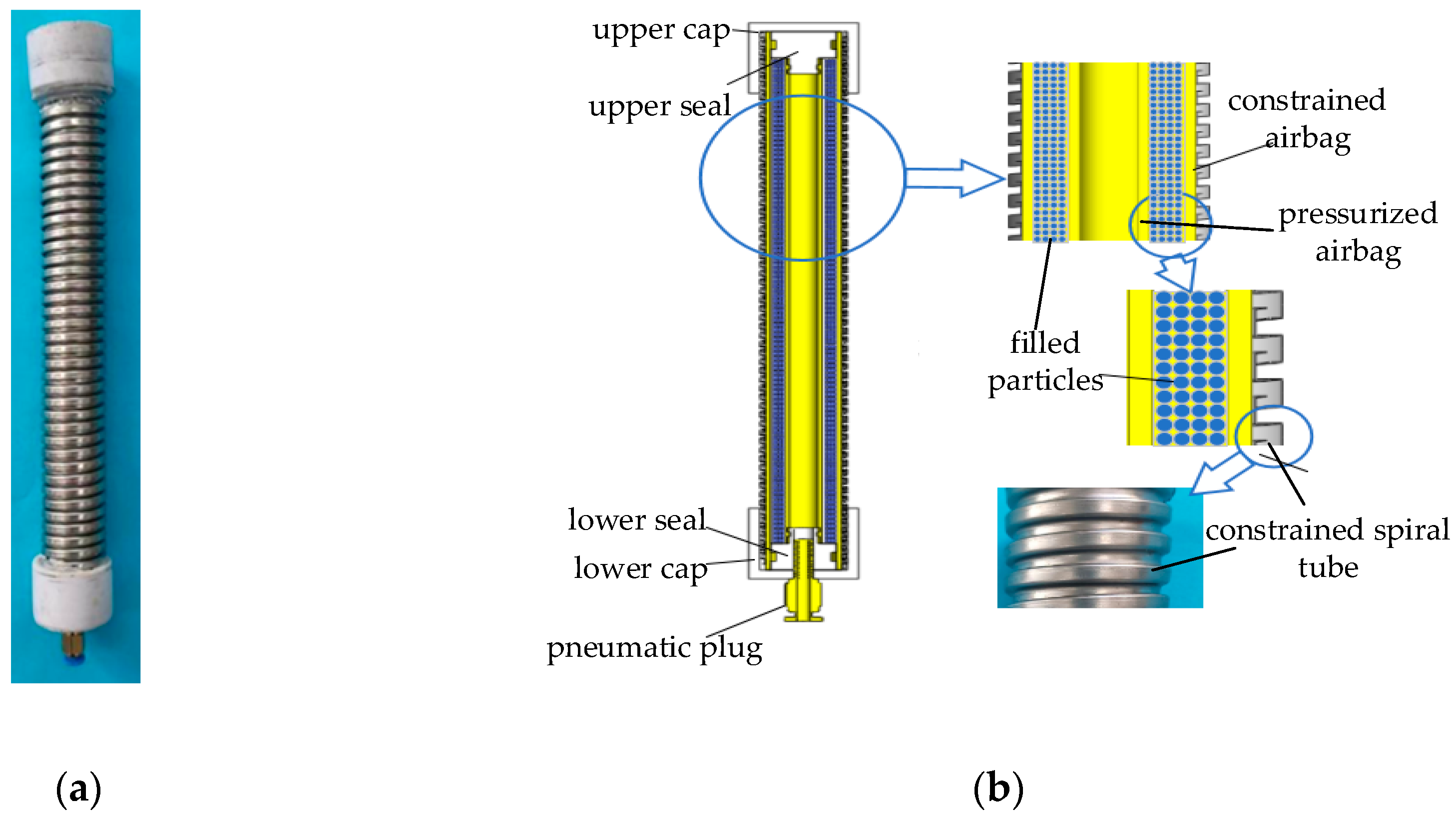
Figure 2.
variable-stiffness principle of variable-stiffness elastic actuator: (a) initial state; (b) elongation under axial force; (c) elongation under lateral force.
Figure 2.
variable-stiffness principle of variable-stiffness elastic actuator: (a) initial state; (b) elongation under axial force; (c) elongation under lateral force.
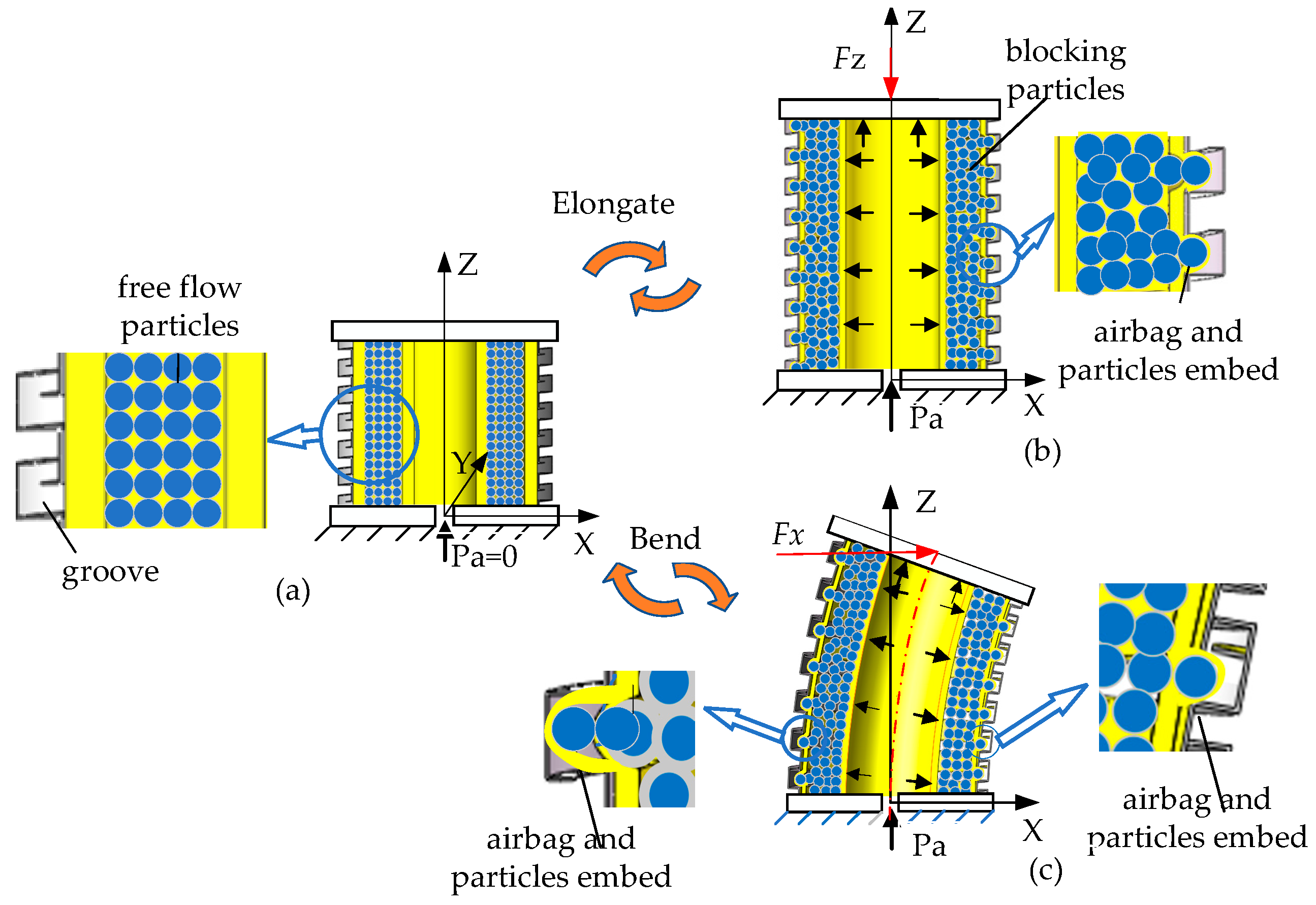
Figure 3.
Force analysis of variable-stiffness elastic actuator.
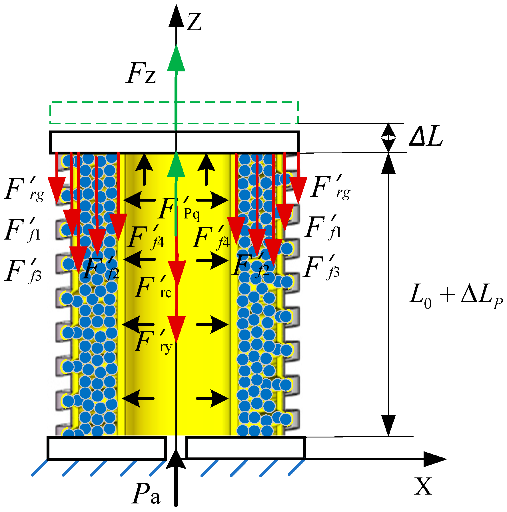
Figure 4.
The friction analysis of variable-stiffness elastic actuator
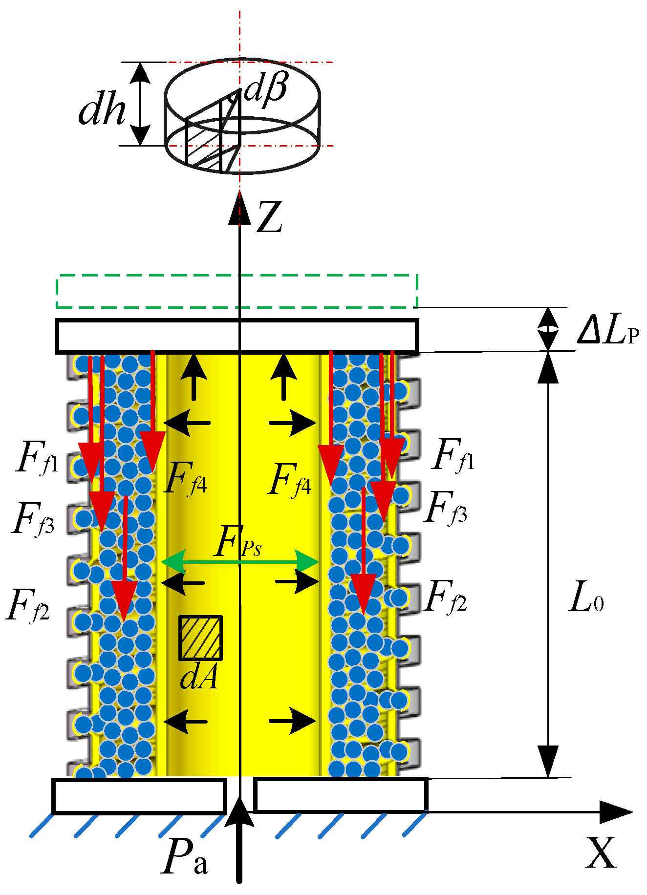
Figure 5.
Force analysis of variable-stiffness elastic actuator.
Figure 6.
Figure 6. Mechanism analysis of wedge impedance force:(a) Embedded volume of particles is less than half; (b) Particles are completely embedded; (c) Force analysis of unit filled particles; (d) Resistance force analysis of wedge mechanism; (e) Force analysis of completely embedded particles.
Figure 7.
Bending force model of variable-stiffness elastic actuator: (a) forced model; (b) Force arm model.
Figure 7.
Bending force model of variable-stiffness elastic actuator: (a) forced model; (b) Force arm model.
Figure 8.
Bending geometric relationship of variable-stiffness elastic actuator.
Figure 9.
anti-tensile ( anti-compressive ) stiffness experimental system: (a) Experimental principle; (b) Experimental device.
Figure 9.
anti-tensile ( anti-compressive ) stiffness experimental system: (a) Experimental principle; (b) Experimental device.
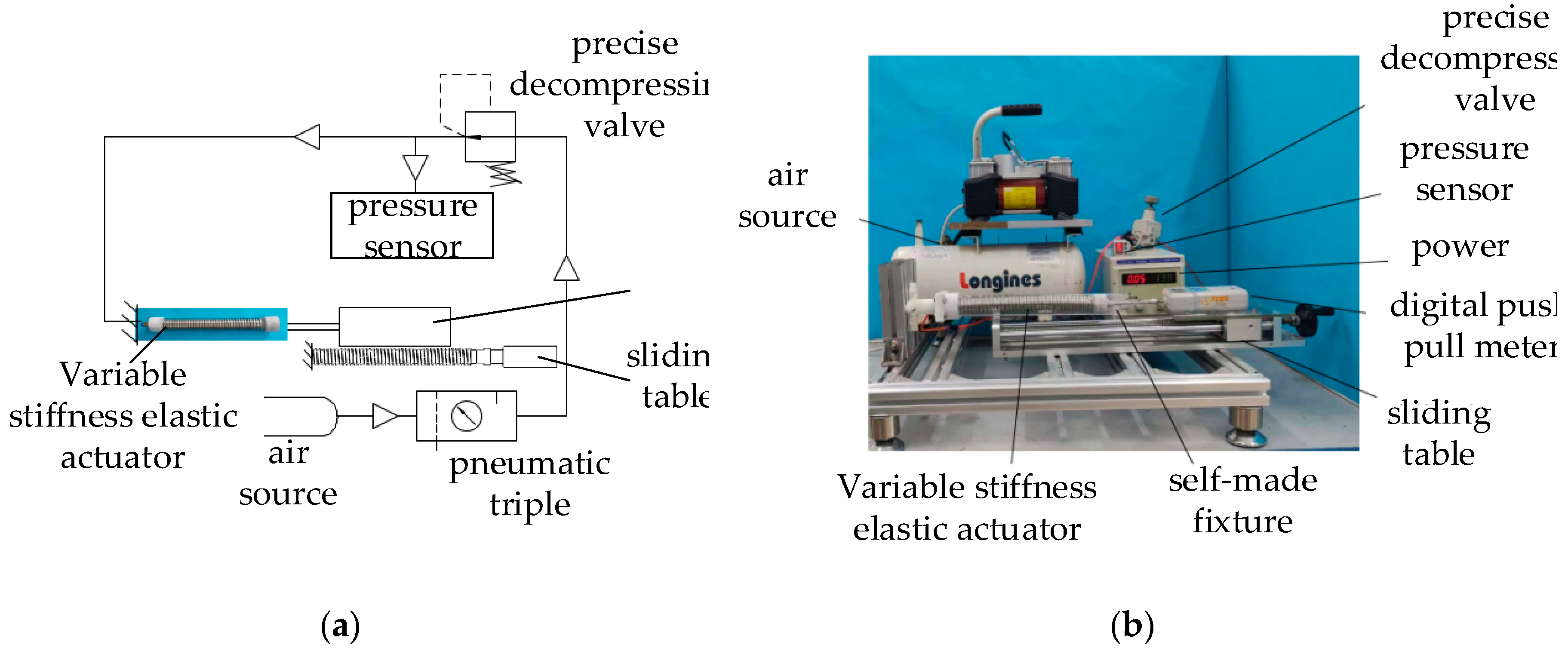
Figure 10.
Comparison of theory and experiment of anti-tensile stiffness.
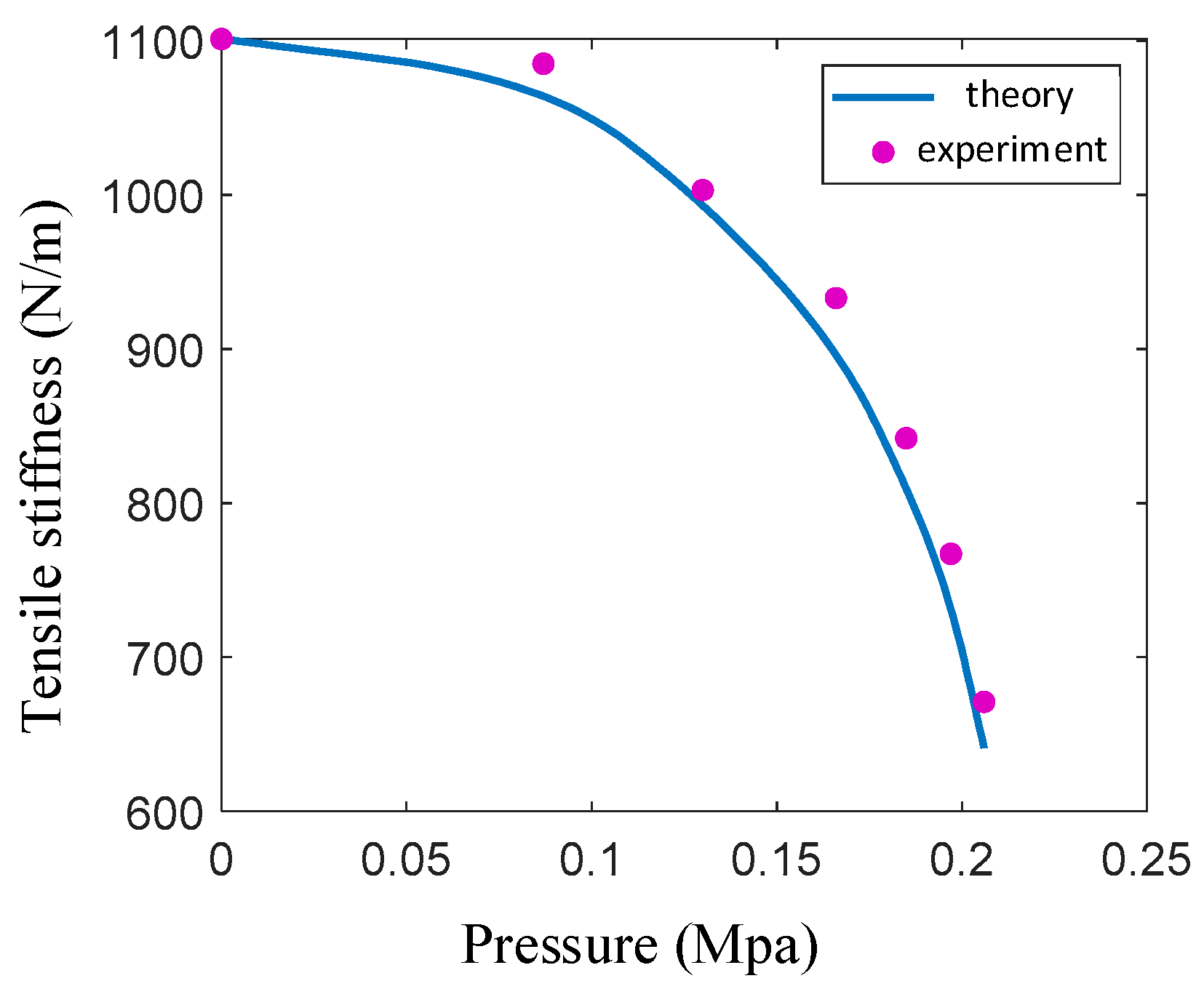
Figure 11.
Comparison of theory and experiment of anti-compressive stiffness.
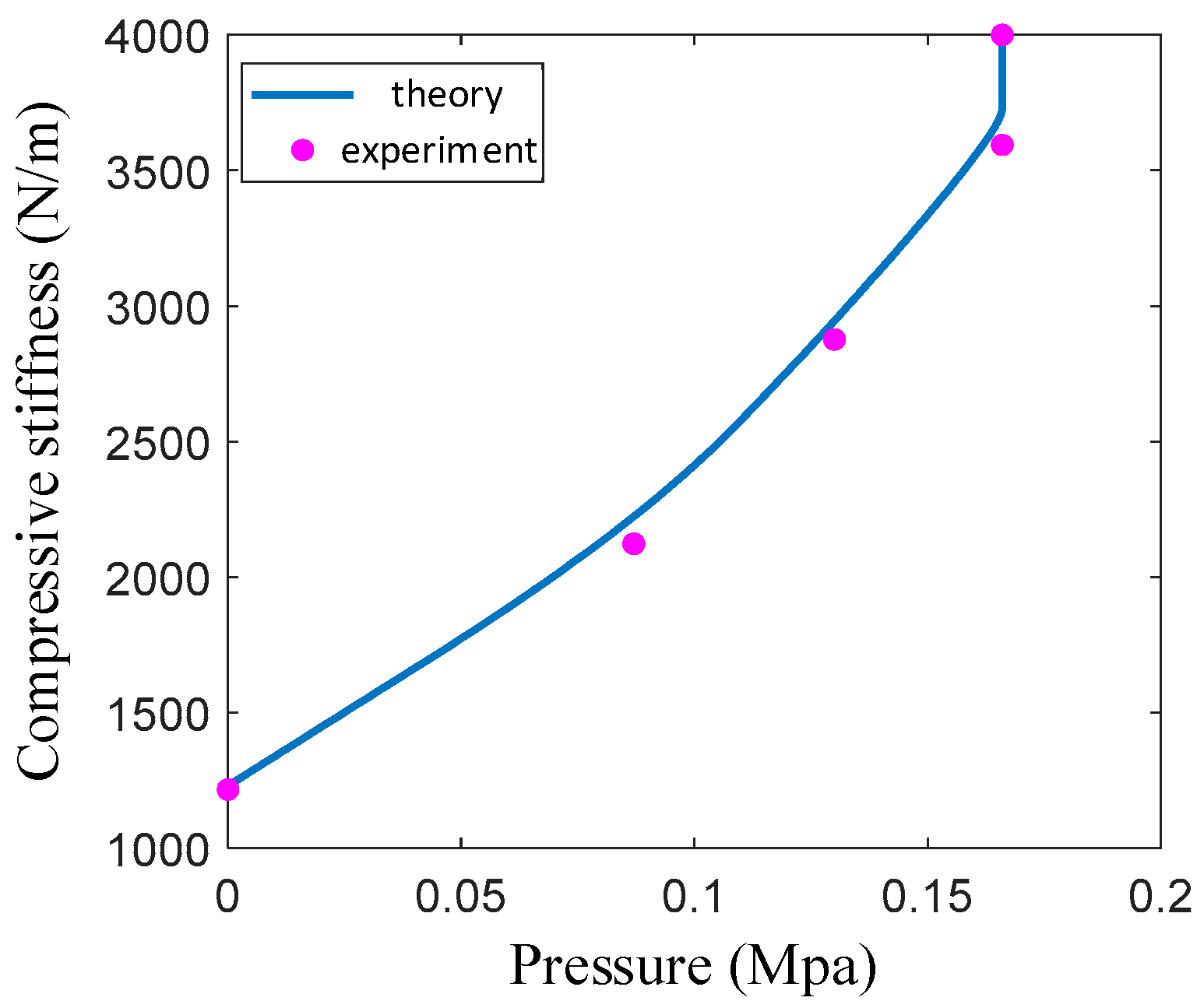
Figure 12.
Transverse stiffness experimental system of variable-stiffness elastic actuator: (a) Experimental principle: (b) Experimental device.
Figure 12.
Transverse stiffness experimental system of variable-stiffness elastic actuator: (a) Experimental principle: (b) Experimental device.
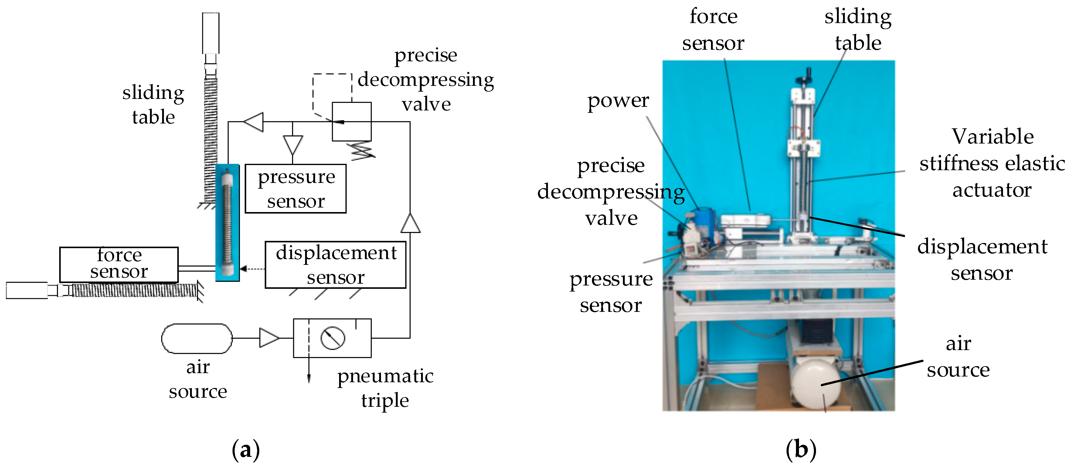
Figure 13.
Comparison of theoretical and experimental lateral stiffness.
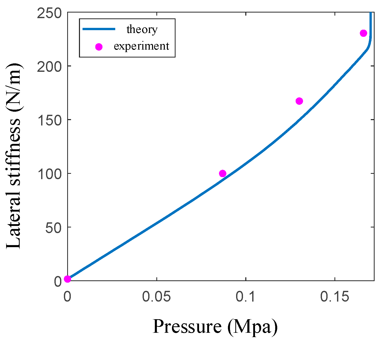

Table 1.
Structural parameters of variable-stiffness elastic actuator.
| parameter name | value | unit |
|---|---|---|
| Overall length | 230 | mm |
| Effective length of airbag | 180 | mm |
| Diameter of pressurized airbag | 8*12 | mm |
| Diameter of constrained airbag | 20*24 | mm |
| Diameter of constrained spiral tube | 25*29 | mm |
| Elastic modulus of airbag | 1.042 | Mpa |
Disclaimer/Publisher’s Note: The statements, opinions and data contained in all publications are solely those of the individual author(s) and contributor(s) and not of MDPI and/or the editor(s). MDPI and/or the editor(s) disclaim responsibility for any injury to people or property resulting from any ideas, methods, instructions or products referred to in the content. |
© 2023 by the authors. Licensee MDPI, Basel, Switzerland. This article is an open access article distributed under the terms and conditions of the Creative Commons Attribution (CC BY) license (http://creativecommons.org/licenses/by/4.0/).
Copyright: This open access article is published under a Creative Commons CC BY 4.0 license, which permit the free download, distribution, and reuse, provided that the author and preprint are cited in any reuse.


