Submitted:
13 November 2023
Posted:
14 November 2023
You are already at the latest version
Abstract
The possibility of a shock wave recovery at a discrete closed interface with a heated gas has been investigated. A two-dimensional model applied to conditions of optical discharges featuring spherical, elliptical, and drop-like configurations demonstrated that non-symmetry in the shock refraction contributes to the specific mechanism of recovery other than simply its compensation. Even though the full restoration of the hypersonic flow state doesn’t occur in a strict sense of it, clear reverse changes toward the initial shape of the shock front eventually take place, thus creating an appearance of a full recovery seen in experiments. From analysis for different interfaces symmetries, the factors determining the recovery dynamics are identified. The results are directly applicable to the problem of energy deposition into a hypersonic flow, however it can be useful anywhere else where the flow modifications following the interaction are important. The dimensionless form of the equations allows applications on any scale other than that demonstrated for the optical discharges.
Keywords:
Plasma Dynamics
; Hypersonic flow
; Shock waves
; Shock refraction
; Shock Recovery
I. Introduction
Shocks interacting with gas inhomogeneities is the research topic having a wide range of applications because of its strong effect on a hypersonic flow. Creating a plasma region in the flow upstream of the body can work similarly to a physical spike thus effectively reducing the wave drag. The forces due to pressure and density redistribution resultant from a plasma being applied locally around the vehicle allow means of effective control of its motion in a hypersonic flight, thus eliminating additional mechanical parts on the vehicle [1]. Other features of the interaction, such as acceleration and weakening of the shock front, are helpful in solution of the sonic boom reduction problem [2], in combustion for optimized ignition dynamics [3,4], and in astrophysics for explanation of the process observed during a supernova explosion [5].
Modifications to the hypersonic flow as the result of the interaction can be done in a predetermined way and includes both, the shock wave structure and the gas state in the media behind the shock. In the applications, the gaseous media within and outside of the inhomogeneity is typically of the same nature but of different gas properties, such as temperature or density. Another class of problems includes isothermal gas conditions and thin film bubbles filled with a gas of a sort different from that of the environment, and it is sometimes combined with the non-isothermal gas conditions. The gas inside an inhomogeneity is usually heated using energy deposition via an RF, microwave, or optical discharges, with pulsed methods of application typically being more efficient than continuous at an appropriate repetition rate. Focused electron beam or localized combustion are among other efficient ways of energy deposition.
In this work, a particular problem of a shock interacting with a closed thermal discontinuity created in a discharge will be considered. It will be mainly focused on modification of the hypersonic flow state as the shock is passing through a volume of heated gas or plasma floating in a gaseous environment of different state properties. Being applied to optical discharges, this would correspond to later phases when expansion of the heated spot slows down. Given the equal gas pressures across the interface, the problem equally corresponds to the interaction with a density discontinuity. To facilitate the geometries most common for experiments, the model will be numerically applied to a planar shock front interacting with interfaces of round shapes.
A complex phenomena arising from the interaction includes intensive modifications to the supersonic flow and to the structure of the heated volume of gas. In case of a regular refraction, upon the incidence of a shock on a heated volume of gas, the shock front splits, with one portion being transmitted through the hot spot, and another one reflected off the interface. When inside the heated medium, the shock front is accelerated, becomes increasingly distorted and weakened, until it becomes less and less identifiable. In case of a bow shock formed in front of a moving body, the shock displaces away from the body in the presence of heating. Re-distribution of the flow parameters following the shock front deformations and strong local reduction of the gas pressure, results in an intensive vortex system setting at the interface. The positive dynamics in the vortex intensity in the aftershock flow suggests not only interface but volume effects as well [6,7]. The sucking effect caused by the pressure redistribution is responsible for a strong distortion and eventual collapse of the heated region span by a non-linearly intensified vortex system. In case of irregular refraction, additional structures feature a triple point with reflected shocks and a Mach stem formed in front of the interface. The model developed here will be specifically focused on the flow inside the hot spot and behind it, thus the irregular structures can be assumed as superimposed on the picture of a regular refraction.
The wave propagating through the heated medium inside the spot generates an internally reflected shock at the impact with the interior of the exit part of the interface, and a shock wave emerging from the hot spot into the outside environment. In experiments, upon exiting the heated spot or during the discharge on-off times, the changes in the hypersonic flow persist for some time in the form of time delays in the effects on the flow and a finite pressure rise time. After fully crossing the hot region, the shock front distortion produced inside the heated region is often followed with the front’s full or partial restoration to the shape initially present at the incidence [8,9,10,11,12].
In describing the front modifications following the shock’s crossing of the heated spot, a model [6] based on the shock refraction mechanism will be used here. In accordance to the model and assuming symmetry in the interaction that includes both the geometry and the gas state across the interface, intuitively the reasons for the recovery seem obvious. However, the fact that the full front restoration is observed not under all circumstances renders looking into the problem in more detail. Considering a planar incident shock front and a discrete type of a curved interface separating the same gas of different properties would allow elimination of a number of non-essential factors, an advantage of obvious comparison, and more straightforward relating of the results to the conditions of most experiments. Under the condition of equal gas pressure on both sides of the interface, the problem is equivalent to the case when the unshocked gas density inside the spot ρ2 is less than that in the gaseous environment ρ1 and that, in terms of Atwood number , is the light gas bubble case of A < 0.
In the model described below, a closed interface enveloping the heated volume of gas will be functionally split into two parts further called as the entrance and the exit semi-interfaces, that in general will be of different shapes. They are distinctly defined by the temperature step experienced by the shock during their crossing. Then the entrance semi-interface is characterized as the one crossed by the shock from colder gas into the heated one, and thus the interaction will be of the slow-fast type. At the exit part, the temperature step is opposite and the shock refraction proceeds in accordance to the fast-slow scenario. Because the processes that occur at each of the interfaces are fundamentally different, two separate solutions should be obtained. Considering an interface of arbitrary shape but having an axial symmetry along the shock’s incidence direction, the problem becomes two-dimensional and thus can be applicable to the cylindrical, spherical and elliptical (in the plane of symmetry) geometries. In the following examples, the model relations will be numerically applied to symmetric as well as to non-symmetric configurations.
II. Interaction at the Front Interface
In this section, the evolution of the shock front at the entrance of a heated volume of gas will be investigated. This first phase of the interaction is limited with the moment of time when the first point on the distorted front propagating inside the hot spot reaches the exit portion of the interface. In the Figure 1, an initially planar shock front (green vertical line on the left) is moving from left to right with constant horizontal (along the x-direction) velocity V1. The shock is incident on an interface of arbitrary shape (black curve) that separates the hot gas with temperature T2 inside the heated spot from the cold ambient gas of temperature T1. It will be assumed that the gas parameters are distributed uniformly on both sides of the interface and the indices 1 and 2 are referred to the cold and hot media accordingly. The local angle of incidence α1of the shock at the interface will be defined as the angle between the shock velocity vector V1 and the normal to the interface at the point of incidence.
At the moment of time t = 0 the first point on the front starts interacting with the interface (on the symmetry axis), and later the interaction point moves along the interface up. At the moment of crossing the interface, the total shock velocity experiences a jump from V1 to V2 that includes both, its value and the direction. The jump is locally dependent, thus the velocity change, together with the time-delay due to the curvature, result in the shock front distortion that continuously increases as the entire front crosses the interface and proceeds further through the heated medium.
The problem of a shock refraction in spherically or cylindrically symmetrical case has been already considered in [6], and the approach can be readily extended here for an arbitrary interface geometry. At the entrance, the shock refraction results in rotation of the velocity vector by the refraction angle γ2 that is a function of the local incidence angle α1 and the temperature step. In the slow-fast scenario taking place at the entrance interface, the x-component of the shock velocity increases from V1 to V2x because of a higher speed of sound, thus resulting in the horizontal stretching of the front. At the same time, from the continuity principle for the tangential components of the velocity, the refracted shock acquires a local vertical component of the velocity V2y pointing toward the symmetry axis and giving rise to the shock distortion in the second direction.
The equations describing the front modification can be derived by following a path of an infinitely small element of the incident front, starting from the moment the first front’s portion touches the heated spot. The components of the front deformation (denoted as X and Y in Figure 1) will be defined in the reference frame moving with the velocity V1, i.e. as the difference in the travel distances in cold and hot media. For a planar incident front, the deformation vector components (X,Y) are equivalent to the front stretching in both directions. Because of the local incidence angle, both deformations are dependent on the initial position of the front’s element relative to the interface (labeled with i in the Figure 1) having the coordinates (x, y). The coordinate x is the function of the travel time to the interface t0 that is counted from the moment when the front is positioned at the origin of the coordinate system, i.e.,
x = V1 t0
The coordinates (x, y) are related to each other with the equation of the entrance semi-interface curve
assuming it as a continuous and smooth function of x in the domain determined by the dimensions of the heated spot.
y = β1(x),
From geometrical considerations, a relationship between the front deformation (X, Y) and the coordinates of the point of contact (x, y) at a moment of interaction time t > t0
where . The refraction angle γ2 (x) is determined by the local incidence angle and the gas conditions across the interface,
where , , and is the ratio of normal components of the Mach number [6]. The incidence angle function α1(x) is determined by the equation of the interface (2),
or can be more conveniently expressed in another form, via the first and second derivatives of β1(x) with respect to x as
The ratio of normal components of the Mach numbers appearing in the factor ε2 in Equation (5) is obtained from the solution of the shock refraction equation [13], assuming that under the conditions at the entrance interface the wave reflected off the interface is a rarefaction wave. In ideal gas, the Mach number ratio is the function of the incident shock Mach number M1, the temperature step and the specific heat ratios k1 and k2.
In relating the front distortion produced at a specific location on the interface to its coordinate, the evolution process can be described in terms of instantaneous rate of its change along the interface at a point (x,y). The directional derivative of the vector field = <X, Y> will be given by the dot product of the unit vector along the interface line and the gradient of deformation
, where is the tensor product.
Considering this along one of the basis vectors, m, i.e., ,
On the (x,y)-plane, the gradient (8) is the 2×2 matrix ∂i Ωj
where ∂i = ∂/xi, and since x and y are related coordinates, only two components of the matrix are independent. Choosing , we come up with the following components to consider,
and the remaining two components and can be determined from the pair (11) using (2) and the relation . Finally, accounting for (1), the deformation rate can be expressed in terms of the time t0 by re-scaling the coordinates with V1.
The rate equations can be derived by following a path of a small element of the incident planar shock front of the width dy located around the coordinate (0,y). It is assumed that the front element is hitting the interface at the location around (x, y) = (β1-1(y), y) and the width of the interface element involved in the interaction, in the second direction, .
Being interested in the shock front state at a number of fixed times t > t0, where t0 = x/V1 is the local time of approaching the interface, the time t can be included in the rate equations as a parameter. Then, for a pair of points on the incident front distant from each other by dy and that are hitting the interface at the locations distant by dx, resulting variation of the incidence angle dα will cause variations in the shock speed ratio dυ21 and refraction angle dγ. Variations in the parameters dυ21 and dγ cause corresponding deformation of the front dδ = (dX, dY), that can be determined using the Equations (3) and (4). Neglecting the second and higher order terms containing differentials dx, dy, dυ21, dα1, dγ2, the two components of the deformation are
Choosing the x-coordinate in the analysis, the rates (11) take the form
and the transition to the related coordinate y can be done via , or for the travel time to the interface using .
The variables γ2 and υ21 are dependent on the local incidence angle α1, and, according to Equations (6) and (7), are the functions of the interaction point coordinates (x,β1(x)) and the gas parameters on both sides of the interface, i.e., γ2 = γ2(x, t0, T21, k1, k2) and υ21 = υ21 (x, t0, T21, k1, k2). Assuming the gas parameters are fixed (uniformly distributed), the temperature ratio can be taken as a constant factor. Then the derivatives of γ2 and υ21 are split as follows
where the derivative appearing in both relations is the function of x only and is determined from the Equation (7)
The second factor in the Equation (16) can be obtained by differentiating Equation (5) with respect to x that, together with (5), yields
where α1 (x) and γ2 (x) are determined by Equations (7) and (17).
The derivative dυ21/dα1 in Equation (16) is found by expressing the total shock velocity V2 in terms of its normal and tangential components and using the property of continuity for the tangential components at the interface, that yields
Together with Equation (5), this can be expressed through the incidence angle
from which we obtain
Finally, inserting the results for derivatives , , and in the Equations (14) and (15), the rates can be expressed explicitly as functions of x and t.
II. Interaction at the Back Interface
At the exit, upon reaching the back interface, the shock experiences the second refraction into the cooler environment. The exit interface will be defined here as separating the hotter medium “2” with temperature T2 and a medium “3” with temperature T3 < T2. The interface shape, assumed to be arbitrary and different from the entrance one, will be described with the equation
y3 = β3(x3)
In case of homogeneous parameter distribution in the medium surrounding the spot, the media “1” and “3” will be same, however a separate labeling will be kept for generality to include the possibility of substantial gradients present in the gas. In the following equations, the index “3” will be attributable to parameters and processes that occur in contact with the back interface or behind it. This includes the incidence angle α3, shock velocity V3, Mach number M3, and refraction angle γ3, as illustrated in Figure 2.
In the diagram below, the green curve on the left is the shock front distorted during its refraction at the front interface, at the moment it has just finished crossing it entirely. The front immediately begins its interaction with the back part of the interface (black bold curve) starting with its top portion, and this is the moment the time t3 starts counting. Due to the second refraction, the shock velocity vector instantly changes from V2 to V3. The green curve on the right is the result of shock refraction at the exit from the hot spot, at a moment of time t3 > 0, when the small element “i” on the initial front reaches the back interface. At this moment the transmission into the medium 3 is only partial, with some portion of the front still approaching the interface.
Because of a lower value of the speed of sound in the medium 3, the magnitude of the velocity vector V3 will be less than V2,. This, combined with the orientation of the back interface being opposite to the incident one (concave vs convex), results in the rotation of the shock velocity vector toward the symmetry axis again. The angle of refraction into the medium 3 can be determined using the continuity property for the tangential component of the shock velocity on the back interface, similarly to the way it was done for γ2. Then, using the definition of the angles given in Figure 2,
where
Modifications of the shock front produced at the back interface will be described with the distortion vector = <X3, Y3>. Its components are defined relative to the flat portion of the front undisturbed by the heated medium, as shown in the schematic diagram of Figure 3. Similarly to that for vector , the components of are defined in the reference frame moving with the velocity V1.
The evolution of the shock front with time will be the main point of interest in this setion. The equations for each component of the front distortion will be obtained by relating the coordinates of a point (xi, yi) on the initial front with its coordinates (X3, Y3) for the front profile exiting through the back interface. Accounting for the initial distortion of the front (xi, yi) acquired at the entrance of the spot, the net distortion vector components at the exit will be δ3x = X3 – xi and δ3y = Y3 - yi.
Similarly to the procedure described in section I, the equations will be derived by tracing a path of a small element i on the initial front (t3 = 0) with time. As shown in the diagram, starting from its initial position (xi, yi), the element is crossing the back interface at the point (x3,y3) and continues its motion behind the spot with the components X3 and Y3.
From geometrical considerations and in accordance to the definitions of the variables given in the Figure 3, the relationship between the coordinates of the initial shock front (xi, yi) and that outside of the spot, (X3, Y3), can be found as follows
Here , the coordinate of the point of interaction x3 is the solution of the following equation
and the set (xi, yi) is determined by the Equations (3) and (4) assuming xi = X, yi = Y. Similarly to the way it was done for the ratio υ21, the shock velocity jump at the back interface
or alternatively
The Equations (25) and (26) can be rewritten in a dimensionless form if all the distances are normalized to one of the interface dimensions, say b3, and the time ‒ to its characteristic value , resulting in
where the bar means the value’s dimensionless equivalent.
III. Shock’s Interaction with a Closed Interface
Heated gas volumes of nearly spherical, elliptical, or drop-like shapes and elevated gas temperatures common for optical discharges are among the characteristics capable of supporting significant refraction effects [14,15]. The symmetry inherent to those shapes will be used in the examples below to numerically demonstrate the extent to which the shock recovery is possible. In exploring the factors controlling the recovery dynamics, partially asymmetrical shapes made of a pair of different semi-elliptical interfaces will be explored. Assuming the uniform gas parameter distribution, the ideal gas conditions, and fixed values of the incident Mach number M1 and heating strength T21, variation in the refraction strength can be narrowed to only one factor related to the interface curvature. This can be controlled by the degree of longitudinal stretching of the interface, and the level of heating will be kept intensive enough for significant refraction while still allowing the ideal gas approximations.
In the following examples, the model relations (3), (4) and (30) will be used in a dimensionless form, however it must be kept in mind that the ratios and entering the factors ε2 (M1, γ1, γ2 ) and ε3 (M1, γ1, γ2 ) are M1-dependent, and thus the incident shock Mach number must still be specified. For easier comparison, all the interface geometries will be tested for the same Mach number of the incident shock M1 = 3.5. The process of crossing of a spot of heated gas by the shock will be split into two subsequent phases, in accordance to the model presented above. During the first phase that occurs at the entrance part of the interface, the initially planar shock refracts into the heated medium and the shock parameters experience instant changes at the interface. This phase also includes the shock’s propagation through the hot medium during which the front experiences a continuous distortion. The second phase starts locally at a moment of time tc, when a front element strikes the interior of the back part of the interface. During this phase, the shock experiences the second refraction into a cooler medium and, after breaking free out of the bubble, still continues its distortion, presumably back, closer to its original plane shape.
Two separate problems corresponding to those phases are connected to each other through the solution of the first problem at the entrance interface {X2(x), Y2(x)} obtained from Equations (3) and (4), being the initial condition for the second problem {xi, yi} in Equation (30), i.e.,
{at t = tc, xi = X2(x), yi = Y2(x) }
The connection, being local, corresponds to the instant of time t and the coordinate of the interaction point (x3, y3) at the back interface. This yields the solution {X3(x), Y3(x)} for the shock front propagating behind the full closed interface at the times t > tc + ta. The local time ta accounts for the travel of a shock front element inside the hot spot to the exit interface that, in the notations depicted in the Figure 3, is determined as . The time domain for the final solution is t3 = t – tc, t3 > max[ta], where the full time t is counted starting from the first moment the initially plane shock front hits the entrance interface.
From the equation of a tangent line at a point on an ellipse
the incidence angle at the entrance part of the interface
Accounting for the rotation of the velocity vector at the entrance of the heated medium, the incidence angle at the back interface
Then the Equation (27) for the coordinate of the interaction point at the back interface x3 takes the form
where (xi yi) is the coordinate of corresponding shock front element at the time t3 = 0 (Figure 3). Here the ellipse’s major semi-axes are denoted as a1 and a3 for the incident and exit portions accordingly, and minor semi-axes are equal, i.e., b1 = b3 = b. Of the three solutions to Equation (35), the one satisfying the boundary conditions,
gives the local coordinate for the shock element crossing the back interface.
The factors and entering the Equations (5), (18) and (23) are the functions of the gas parameters on both sides of the interface, the incident wave Mach number, and the degree of the interface sharpness [7] only. Since the factors are not geometry dependent, they will enter the equations as constants.
In determining the ratios and , qualitatively different processes taking place at the two semi-interfaces must be considered. In accordance to [13,16], in case of moderate gas heating and no dissociation, the nature of the wave reflected off an interface is determined by the temperature step across an interface only. In the slow-fast scenario of the interaction present at the entrance interface, i.e., when T21 > 1, and when M1 is not very close to the unit [16], the reflected wave is a rarefaction wave. Assuming the interface is sharp, the normal component of the Mach number M2n is determined from the solution of the corresponding refraction equation (A1) given in the Appendix. With the known value of the incident shock Mach number M1, the ratio M(n)21 can be determined at every point of interaction. At the back interface T32 < 1, and the interaction proceeds in the fast-slow scenario in which the reflected wave will be a shock. In this case the Mach number ratio is obtained from the Equation (A2) in the Appendix. Having M2n known from the solution to the previous equation, it is solved for M3n and the corresponding ratio is determined. In case the parameter distribution in the surrounding medium is uniform, T1 = T3 and the specific heat ratios k1 = k3 are taken.
Both solutions M2n(M1n) and M3n(M2n) obtained for diatomic nitrogen at T1=300 K, T2 = 2000 K, and M1 = 3.5, and assuming the gas pressure atmospheric, are presented in Figure 4.
The Mach number experiences a jump down at the entrance of the heated spot (plot a), i.e., M(n)21 < 1, and the ratio’s behavior is opposite at the exit of the spot where M(n)32 > 1 (plot b). The solutions represent nearly straight lines, and thus the ratios can be approximated as linear functions.
Now, with the values and in place, the solution for the shock front distortion is obtained using the system of Equations (3)–(6) and (20) at the entrance, and (24), (30) and (34)–(36) at the back interface, being connected with the condition (31). In the next paragraphs, the shock distortion followed with its recovery will be numerically tested for several interface geometries.
IV. The Case of Spherical Symmetry
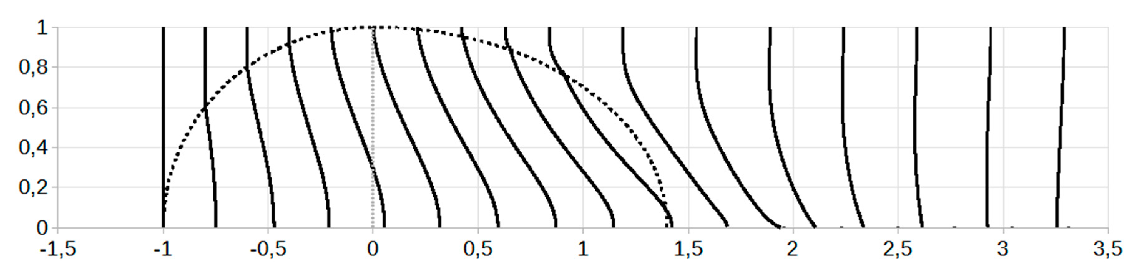
A spherical interface features the symmetry as one of the conditions necessary for the full front recovery. The results of numerical simulation presented in the Figure 5 are obtained using the relations (3)–(6) and (20) and (24), (30) and (34)–(36) with the ellipse major semi-axes taken equal, b = a1 = a3, for a shock of M1 = 3.5 propagating in diatomic nitrogen gas of T1 = 300 K, T2 = 2000 K, and T3 =T1. On the graph, the curves demonstrate transformation of the initially planar shock front, moving from left to right, during its transition through a spherical hot spot.
The coordinates of the shock profiles (X,Y) at the entrance, and (X3,Y3) at the exit, are normalized to the distance b. The curves correspond to a number of dimensionless times
where τ = a3/V1 is the characteristic time. The sequence of the distorted fronts is presented as three bunches of curves highlighting critical moments of the interaction. The first bunch (6 curves crossing the entrance interface) is plotted through the equal time intervals of Δnτ = 0.2, for the next three curves crossing the exit interface the interval Δnτ= 0.15, and Δnτ= 0.3 for those propagating free behind the spot.
nτ = tτ /τ
The graph demonstrates an increasing distortion of the shock front at the entrance until the first front element strikes the interior of the exit interface (first 8 curves). During this phase, the central part of the front (next to the longitudinal axis of symmetry) is mostly affected due to incidence angles and longer interaction times. When the front reaches back interface, the interaction conditions change. Contrary to the situation at the entrance, when the front begins interaction at the central area (y ≈ 0), at the exit the front crosses the interface starting from the periphery (the sphere pole, y ≈ 1). Due to longer interaction times with a cooler gas, a delay in the propagation for these front elements relative to the rest of the front results in its gradual flattening, while the front’s central part still continues its stretching in the same direction. The net result during this phase is a more distorted front to the degree that keeps increasing for the entire time of exiting through the back interface.
After the shock breaks free out of the hot spot, even the condition of the uniform gas parameter distribution in the surrounding medium does not preclude the front deformations from continuing. While the x-component of the shock velocity can be partially compensated in the transition to a medium with a lower speed of sound, the non-zero and locally dependent vertical component of the velocity drives the front distortion further. As it is seen in the Figure 5, starting from the periphery, the increasingly larger portions of the front start to transform back to its original shape owing to the motion of already flattened elements toward the center. The increasing flattening of the front can be also seen by tracing the inflection point on the curves that is steadily approaching the symmetry axis. Finally, at the distance approximately twice the spot size, the entire front becomes perfectly flat thus reaching its full “restoration”. This moment is not shown in the figure to keep a meaningful scale, however the last few curves clearly show the trend. Thus, in the spherical geometry of the interaction, the front recovery time is longer but comparable to the time of distortion attained during its propagation inside the heated medium.
Regardless of the anti-symmetry in the gas conditions at the entrance and the exit of the heated spot (T2/T1 > 1 and T3/T2 < 1), the interface’s opposite orientations (curvature sign and value) result in the rotation of the velocity vectors V2 and V3 in the same direction, toward the longitudinal symmetry axis. As the consequence, after crossing the back interface, a larger vertical component of the velocity V3y (Figure 6f) gives rise to an intensive motion of the front elements from the periphery to the symmetry axis. Thus flipping of the total interface’s action on the flow twice results in the front refraction in the same direction. In cases of strong enough refraction, the intensified transversal motion of the front elements can result in the central parts of the front collapsing at the symmetry axis. With both outcomes however, this motion component is able to support the “recovery” of the front to its original shape by closing the disturbance “hole” with increasingly flattened periphery portions of the front coming toward the symmetry axis.
The shock parameter distribution along the interface (its y-coordinate) presented in Figure 6 provide the details that support the data above. As the plot of Figure 6A shows, the value of the refraction angle γ3 at the exit always exceeds γ2. The main reason for this is the difference in the values of the angle of incidence on the two semi-interfaces, where at the entrance the shock is incident horizontally, while at the exit it strikes the interface under the angle γ2.. This increases the effective incidence angle from αentr = α1 at the entrance to αexit = α3 + γ2 at the exit (Figure 6b) resulting in a larger angle γ3. With the incidence angles being largest in the middle area closer to the symmetry axis and tending to zero at the periphery, a larger normal component of the shock velocity more strongly contributes to the effect in proximity to the axis. The specific distribution of the incidence angles result in the refraction angle peaking near the symmetry axis of the hot spot.
The shock velocity jump υ32 across the exit interface is found to be not that intense compared to the inverse of υ21 at the entrance (Figure 6c). Thus, even in the case of full symmetry across the interface (geometry and the gas state), the velocity ratios υ21 and υ32 are not reciprocals. Fundamentally different processes that occur at the two interfaces during the shock reflection (reflected shock or rarefaction wave), the shift in the incidence angles, and corresponding shock energy losses are the reasons for non-symmetrical distributions for the Mach number ratios (Figure 6d) and the shock velocities.
Regardless of the visible “recovery” seen in the front shape, the intensity of the shock emerging from the hot spot is remarkably reduced due to losses associated with the two consecutive reflections. For a particular set of flow parameters used in Figure 6, the absolute value of the shock velocity V3 at emergence from the heated spot (on the symmetry axis) is reduced compared to its initial value V1 at the entrance by the factor of 0.7 (plot e). The effect is common for the rest of the front surface however continuously weakening in the off-axis area and vanishing to none at the periphery. The loss of shock intensity can also be noticed in the last 4 curves in the Figure 5, where the front portions gone through the spot increasingly fall behind with its outside part undisturbed by the interaction. Variation in the amount of reflected energy, being dependent on the normal component of the shock velocity, results in the losses being highest at the symmetry axis. They are continuously diminishing as the point of interaction approaches the periphery where the incidence angle tends to zero.
It can be concluded then that, regardless of the possibility of a shape recovery, in a strict sense of it the shock disturbance by the heated spot is not fully reversible. Even with significant development of the front back to its original shape in the longitudinal direction, the mechanism of the front “recovery” turns out to be not of a pure compensation type. The appearance of return to the original front shape occurs as the result of collapsing of the perturbed portion of the front at the symmetry axis and its replacement with centripetally moving flattened portions of the front from the periphery. In accordance to Figure 6f, the middle portion of the front is the one most heavily involved in the centripetal motion. The re-arrangement of the flow ceases at the sphere poles, thus preventing the undisturbed portions of the front from participation in the process. As the result, the “hole” in the flow created as a disturbance to the front by the hot spot, eventually closes by overlapping with increasingly flattened portions of the front meeting each other at the symmetry axis.
V. The Dynamics of the Front Deformation
With the purpose of tracing how quickly the front deforms as the point of interaction moves along the interface curve (on the plane), an analysis of its dynamics will be done in terms of deformation rates defined in section I. Information on this property is important because of the tendency of an intense vorticity generation in the post-shock flow tied to the locations of inflection points corresponding to the most rapid/steep changes of the shock profile. The vorticity is triggered at the interface with a heated gas volume, however it is the plasma parameter distribution inside it that distinctively determines the vortex intensity, size, and the growth rate [17]. Depending on the application requirements, finding the locations producing the most intensive front modifications can be important whether the vorticity production is ether a desired outcome or an unwelcome side effect.
In this connection, the matrix components (ℜxx, ℜxy) describing the changes in the front deformation will be tied to the interaction point coordinate, with the purpose of locating the rate’s maximum and minimum values. Because of the relationship (1) between the front displacement and the time of approaching the interface, the interaction point coordinates (x,y) and the time t0 are interchangeable, and thus differentiation in the equations can be considered with respect to either of them.
First considering the interaction at the spot entrance and choosing the coordinate x as the variable, we use the equation of an ellipse centered at x = a
and Equation (6) to determine
and, using (5) or (17), the derivative is obtained. Then, from Equations (18)–(21), the factors , and are determined as functions x and t, and finally the rate components ℜxx and ℜxy are obtained from the Equations (14) and (15). To trace the changes at later times, when some portions of the shock profile are traveling free behind the spot, the relations can be numerically run at several instants of time using the time t as a parameter.
In the Figure 7, the components ℜxx (graph a) and ℜxy (graph b) were determined for the case of a spherical interface, a = b. The rate components are plotted vs the dimensionless coordinate x/a, at the same instants of time and the shock and gas parameters as in Figure 5 and Figure 6. On both graphs, the time sequence is from lower to upper curve and each curve corresponds to a dimensionless time starting at nτ = 0.2 through the equal intervals of Δnτ = 0.2.
In accordance to the results in Figure 7a, the values of the rate component ℜxx are highest near the symmetry axis (x = 0) and diminishing to zero at the periphery of the hot spot. The rate exhibit a positive dynamics that is linear along the whole interface. The highest values of another component, ℜxy (graph b), are also located around the symmetry axis. They sharply drop in the middle area and then slowly decrease to zero as the interaction point moves toward the periphery. With time, the rate decreases in the area around the axis. In the middle area it saturates at a limited level that tends to zero as the interaction point approaches the sphere pole. Thus the graphs show that, during the shock’s crossing the entrance interface, the front experiences the most fast/steep deformations in both directions near the spot’s symmetry axis. As the interaction progresses moving the interaction point toward the periphery, the rates have a tendency of gradual decrease. They both eventually cease to zero at the sphere’s poles thus satisfying the boundary conditions.
Similarly to the analysis done at the spot’s entrance, the rates describing the front restoration at the exit can be obtained. The purpose of the analysis will be locating the points on the exit interface critically responsible for the front recovery. The rate components at the exit labeled as (ℜ(E)xx, ℜ(E)xy) can be determined using the approach of section II, by varying Equation (29) with dx3 along the exit interface. Neglecting the quadratic and higher order terms containing variable deviations dx, dx3, dα, dγ, dυ in the equations and in the Taylor series expansion of the functions, we obtain
Alternatively, the rates can be obtained directly by differentiation of Equations (25) and (26) with respect to x3, resulting in bulkier expressions presented in the Appendix III.
Here in the system of equations
the derivatives of the shock refraction parameters are determined from Equation (18) as
and from (29)
The factors and are obtained from the expressions (14) and (15) that are functions of x1, with the substitution x1 ≡ x and via the transition . Finally, using the above results, we obtain the derivative in (45) via
The scale factor relating the coordinates of the interaction point at the entrance and then at the exit interfaces, is obtained using the geometrical relationship
from which
Thus the locations of the events that occur at the exit from the spot can be traced back to the original coordinate of a small front element of the incident shock. Using the Equation (5) for an elliptical interface at the entrance, and that at at the exit
The Equation (47) can be solved for x3 from which the derivative is obtained. Applying this to a sphere (a1 = a3 = b) of 0.5 mm diameter, the derivative can be obtained in a numerical form as the function of x1
that will be used later in the example below. Finally, using this function in the Equations (41) and (42), the components of the front deformation rates ℜ(E)xx (graph a) and ℜ(E)xy (graph b) at the exit are obtained.
The results of numerical simulation for the rates vs the coordinate y3 of the point of interaction are presented in Figure 8. They are obtained for the same flow conditions as in Figure 5 and Figure 7, at several instants of dimensionless time n3 between 0.2 and 1.8 through the equal intervals of 0.4, where n3 = t3/τ and τ = b3/V1. In the plots, the coordinate y3 is normalized to b3. The curves correspond to a few moments of the shock’s crossing the exit interface (nt < 1) and when it propagates free in the cooler medium behind the spot (nt > 1). The time sequence for the curves is from lower to upper curve in the graph (a), and from upper to lower in the graph (b).
Similarly to that at the entrance, the front deformation rates here are tied to the coordinates (x3,y3) of the interaction point as it moves along the exit interface curve. The purpose of the analysis is finding the locations (x3m, y3m) on the interface producing the most rapid reverse changes of the shock front. Using the relationship (47), those locations can be traced back to the corresponding coordinates (x1m, y1m) at the entrance interface, thus revealing the role of every particular portion of the entire interface in the effectiveness of the front perturbation.
The negative rates ℜ(E)xy in the Figure 8b reflect the fact that the front element’s motion in this direction is still down to the symmetry axis, and its increasing absolute values with time point at a positive dynamics in this direction. The rate values, being significantly higher at locations near the sphere pole (y3→0), identify the periphery and a middle portion of the interface as producing the most rapid front modifications.
The beginning of the front recovery process is seen in the Figure 8a, where the curves for ℜ(E)xx cross the zero line. The rate’s negative values during the first moments of the front’ exit describe gradual flattening of the front at its periphery, and the transition to positive values reflects the fact of its widening at a later time (Figure 5). Reversing the sign of the rate’s values confirms the delay in propagation of the periphery parts of the front relative to that at its center (Figure 5). As the point of interaction slides down toward the symmetry axis (y3→1), the deformation rates ℜ(E)xx decrease and then become negative, thus confirming the progressive flattening of the front near the symmetry axis. In Figure 5, the process of the front recovery can be also traced looking at the inflection point steadily moving down the curves toward the symmetry axis, with its coordinate corresponding to that of crossing the zero line in Figure 8a.
VI. Elliptical Interface Stretched Transversely
In identifying parameters controlling the front recovery dynamics, the effect of the interface geometry will be explored. Compared to a circular, an elliptical interface stretched in the transverse direction (a1 = a3 = a, b>a) will effectively decrease the interface curvature while still keeping the factor of symmetry. The curvature affects the intensity of the refraction effect via two factors, the local incidence angle and the time of interaction with the heated medium. Thus the question is whether the softer refraction will be able to accomplish the full recovery and if, how it affects the recovery time. Since such a shape is most common for optical discharges, the analysis results can be validated using available experimental data.
The results of numerical simulation done for a shock interacting with a transversely oriented elliptical interface are presented in the Figure 9. The shock profiles were obtained using the system of Equations (3)–(6), (20), (24), (30) and (34)–(36) under the same flow and gas conditions as in the case of sphere. In the figure, the fronts entering the hot spot correspond to dimensionless times starting at nτ = 0.2 through the equal intervals of Δn τ = 0.2. For the next four fronts crossing the back interface Δnb = 0.1, and for the rest propagating free behind the spot Δnb = 1.0. The coordinates of the profiles (X,Y) are normalized to b, and the ratio for the major semi-axes of the ellipse b/a = 5/2.
Compared to the case of spherical symmetry (Figure 5), the results predictably demonstrate that a softer refraction on a less curved interface produces a weaker distortion of the front propagating inside the hot spot. Upon emergence from the spot, the full front flattening still occurs but much later, at the distance at least 3 times longer than the characteristic length b (not shown in the picture because of optimal scale). Note the front distortions during its free motion behind the spot being much larger compared to those acquired inside the spot. Thus restoration of the front shape in this case takes significantly longer than for its distortion. The front’s collapsing on the symmetry axis also occurs later than in the spherical case, starting at x = 2.25. Consequently the transverse stretching of the interface delays the front recovery, in the proportion to the degree of stretching.
In discussing the reason for this, seemingly a softer refraction on a less curved interface resulting in a weaker front distortion inside the spot should shorten its recovery time outside the spot (relative to its characteristic time). However, considering the key role of the vertical component of the velocity in the recovery mechanism, a relatively longer pass of the front elements in the y-direction (proportional to the stretching degree) is the deciding factor contributing to longer recovery.
VII. Asymmetrical Interface Stretched Longitudinally
An asymmetrical interface made of two semi-ellipses of different semi-minor axis lengths can model drop-like shaped spots often observed in optical discharges. As a particular case and for easier comparison, the entrance part of the interface will be kept of a circular shape (a1 = b) to produce the initial front distortions identical to those in Figure 5. The exit part of the interface will be taken as elliptical, now stretched in the longitudinal direction. The ellipse’s semi-major to semi-minor axes ratio b/a3 = 5/7 will provide stretching 3.5 times more compared to that in Figure 9.
Based on the previous results, a stronger refraction on a more curved interface and a smaller ratio of the front element paths in transversal vs longitudinal directions, suggests expecting shorter recovery times. In Figure 10, the curves crossing the entrance interface correspond to several dimensionless times through the equal intervals of Δnτ = 0.2 (first 6 curves), Δnb = 0.15 for the next four exiting through the back interface, and Δnb = 0.25 for those propagating freely behind the spot. The profile coordinates (X3,Y3) of the front behind the spot are normalized to the distance b and correspond to the same flow conditions as in Figure 9.
The graph demonstrates that a longitudinally stretched interface supports much faster recovery owing to a relatively shorter travel distance for the front elements in the transverse direction. Compared to the previous results in Figure 5 and Figure 9, the shock emerging from the spot collapses at the axis earlier, at a distance of approximately ½b. The front attains visible flattening also earlier, and becomes fully restored at the distance equal to the spot size a1 + a3 (almost there on the graph).
VIII. Conclusions and Discussion
In this work, the possibility of a shock front recovery at a discrete closed, concave-convex interface with a thermal inhomogeneity has been investigated. The main points of interest were the mechanism of shock recovery, the factors determining whether it is full or partial, and the parameters controlling the recovery dynamics, including the recovery time. Considering one-axis or a full symmetry, a two-dimensional model of the interaction has been developed and then applied in a number of examples. Diatomic nitrogen gas of ambient temperature T1 =300 K heated to 2000 K inside a closed interface, and the uniform gas parameter distribution has been used as a model medium of interaction. The ideal gas approximation appropriate for such conditions allowed elimination of a number of secondary factors, however real-gas and non-equilibrium effects often accompanying this type of interaction can be readily accounted for in the case of higher temperatures, specific sort of gas, or the presence of impurities, as was done for ex. in [13,18,19].
The solution to the problem has been split into two parts, each considering the interaction with the entrance and exit semi-interfaces separately, with the flow parameters being tailored at the junction between the interfaces. The model allows solution at extended times, after the shock front leaves the heated spot and continues its propagation free in the cooler surrounding medium. An incident shock wave of a planar geometry has been chosen for its symmetry, obvious comparison, and because of the prevalent experimental data available in the literature. However extending the model for other shock geometries does not take much difficulty, for ex. using the approaches described in [6]. For illustration purpose and to explore the possibility of controlling the recovery, the model relations have been applied to the conditions common for optical discharges featuring spherical, elliptical, and drop-like configurations. From analysis of interaction with different shapes, the interface stretching degree has been found among the factors controlling the recovery time. In the case of full symmetry in the interaction, an analysis of the dynamics in the front distortion has been made with the purpose of identifying locations on the interface responsible for the most rapid front modification. The dimensionless form of the equations makes it applicable to the problems of any other scales.
One of the most interesting take outs of the research is the non-symmetrical nature of the shock refraction taking place at a closed concave-convex interface. It was demonstrated that, even in the case of totally symmetrical conditions across the interface, the specific mechanism of the shock recovery is something other than simply its compensation. In a strict sense of it, the full restoration of the shock occurs neither at the moment of shock’s emergence from the spot, nor at a later time. At the same time, clear reverse changes toward the initial front shape eventually take place thus creating an appearance of a full recovery seen in experiments.
Another important fact following from the model is that after the shock leaves the discharge, its front distortion does not stop but still continues for an extended period of time comparable to the time of the shock-spot interaction. The impulse given to the front in the transverse direction, characterized by the shock velocity components V2y and V3y, initiates motion of the front elements toward the longitudinal symmetry axis until the central part of the front collapses on the axis. After that, the continuing motion of increasingly flattened portions of the front from the periphery toward the symmetry axis eventually returns the front to its original planar shape by closing at the spot’s center.
At the periphery, a weaker refraction characterized by relatively small y-components of the shock velocity and tending to zero at the sphere pole, makes compensation of the front portions in the x-direction quite effective. The x-component of the front distortion, thus almost unaffected by the transversal motion at this location, results in the front’s continuous flattening with time. With the transversal component of the motion being present, the front’s shape restoration is finished as soon as the last front element (at the pole) reaches the symmetry axis, thus filling the gap of disturbance. Consequently, the appearance of return to the original front shape occurs as the result of elimination of the disturbed patch of the front in its collapse on the symmetry axis, followed by its replacement with centripetally moving periphery flattened portions of the front. The “hole” created as a disturbance to the front eventually closes by overlapping with its external front portions.
However, defining the recovery strictly, a number of factors that take place differently on the two parts of a fully symmetrical interface contribute to preclude the return of the shock to its original state. First, the losses of the shock energy associated with the two consecutive reflections off the interface prevent the shock from its full restoration in terms of intensity. In addition, the permanent loss of the hypersonic flow state occurs because of three major factors. First, the fundamentally different nature of the waves reflected off the two semi-interfaces result in the jump of local shock velocity υ32 at the exit being not that intense compared to the inverse of υ21 at the entrance of the spot, and thus, even under the condition of the full symmetry, the velocity ratios υ21 and υ32 are not reciprocals. The difference in the incidence angles αentr = α1 and αexit = α3 + γ2 due to a non-zero refraction angle γ2 is the second reason. However the key, and the strongest factor in the forever loss of the flow state is non-symmetry in the shock refraction. The opposite orientation of the two semi-interfaces, together with the opposite temperature steps across them, flip the symmetry twice thus turning the velocity vector at both interfaces in the same direction. This results in the y-component of the velocity never being compensated but rather increased at the exit from the spot. The finding immediately suggests that, if there is a desire to directly compensate the front shape, a closed convex-to-convex or concave-to-concave interface will do the job.
From the analysis of interaction with different symmetrical and non-symmetrical elliptical interfaces, the degree of their stretching is found to be among the factors controlling the recovery time. Orientation of the stretching affects the recovery dynamics mostly via the path lengths ratio in the transverse vs longitudinal directions. Compared to the transverse orientation, the longitudinal stretching results in much faster recovery owing to a relatively shorter pass for the front elements from the periphery to the center. Compared to the spherical case, both orientations result in the recovery times directly proportional to the degree of the interface stretching. Thus it can be concluded that, regardless of the shape or orientation of the interface stretching, the front recovery will always occur and it is only a matter of time when. It follows then that it could be that a partial front recovery is recorded in some experiments simply because of too short observation time.
The key statements following from the model, such as the front’s alterations continuing well after it leaves the spot, and the shock’s overstretching followed by its collapse at the symmetry axis, are in a good agreement with experimental observations in discharges of various types [8,11,12,13,14]. For example in ref. [8], the effect of plasma was found to be not confined to the vicinity of a heated gas region but rather it influenced a larger region of the flow field. The front’s continuous changes were observed for extended times (on the order of 1 ms) after it emerged from the heated area or the discharge was switched off. The reported alterations of the shock wave structure inside the hot spot also include the change of the shock front shape, its upstream displacement with a larger shock angle, and tumultuous and highly diffused form of the shock front until its full or partial elimination in the discharge central area [11,12,13,14]. As it was shown in the examples above, the exact time of the front recovery is dependent on the spot’s shape, its size, and the heating strength T2/T1, thus, in relating it to the experimental data, the spot’s dimensions have to be scaled in. In any case though, the recovery times being on the order of the times of shock’s transition through the hot spot, agree well with the observations.
In discussing simplifications imposed on the model, the following factors limiting its validity must be taken into consideration. First, at the higher level of heating and in certain gases, the excitation of slower degrees of freedom in the gas can result in the jump parameter ratios for the shock be substantially different from its ideal gas equivalents. For example, in diatomic nitrogen gas at 3000 K, there will be an 11% increase in density jump across a shock, and a 17% temperature and an 11% pressure decrease, compared to the levels predicted by Rankine–Hugoniot relations [13]. This noticeably influences the shock refraction strength and the flow modifications through the Mach number ratio M(n)21 = M2n/M1n that now should be determined from the shock refraction equations modified for the real-gas effects. With those corrections, the interface reflectivity decreases resulting in 12% more intense shock transmission. The coordinate of the transition point determining the character of reflected wave also shifts, being quite sensitive to the incident shock strength and the sort of gas [13].
In this connection, the sort of gas as a working medium is also a factor. In certain gases and under specific range of conditions, the energy content of inert degrees of freedom can vary greatly, affecting the rates of their excitation dramatically. For example, in O2 and N2 at very low pressures, considerable dissociation can result in the density jump across a shock exceeding the maximum ideal diatomic value of 6 by several times, up to the value of 25. The presence of even a minuscule amount of impurities, such as water vapor, may significantly alter the chemical reaction rates that sometimes flip the tendency in the excitation rate dynamics to opposite of that in a pure gas [20]. While in pure gases dissociation in N2 or O2 molecules can be conveniently disregarded because of their uniquely large mean free paths compared to that for vibrations, collisions with water molecules at room temperature are very effective in exciting vibrations of O2 molecules. At just at 1% of water in the air, the collisions with H2O will be 3 times as effective as all the nitrogen. In the mix, the collisions with water molecules are more effective than those with N2 at 500 K, but less effective at those higher than 700 K. The effect is due to the relaxation time quickly decreasing with temperature for collisions with N2 and much slower for collisions with water molecules [21].
The way different types of discharges can heat the gas is another factor to consider. For example, in the microwave discharge, the contribution of rotational–vibrational bands of molecular nitrogen considerably prevails over that of atomic line spectrum [22] and the pulse-repetitive discharges can feature much stronger dissociation processes [21]. And the specifics of discharges combined with sort of gas provide a full spectrum of intermediate outcomes. For example, in metastable oxygen, colder discharges tend to produce molecules, while at higher temperature conditions atomic oxygen prevails. At the same time, when using the He/O2 mixture, the microwave cavity discharges favor molecular production, but an arc-seeded microwave torch in air shows preference for atomic production [23].
When the gas heating level is increasing, the presence of non-equilibrium in the gas state also affects the interaction. In N2 it starts at around 5000 K, however, given a complicated dependence on the sort of gas, this number can vary greatly. Because of the lag in achieving the equilibrium state, a zone of variable specific heat with continuously changing gas parameters forms behind the shock front. An extended structure acquired by the front is important to consider when the spot dimensions become comparable to that of the structure. In addition to the gas temperature, the effect is also dependent on the shock’s Mach number. Thus, considering a curved interface, the parameter distribution and the local width of the relaxation zone, being dependent on the normal component of the Mach number, is affected through the incidence angle. For moderate-to-strong shock intensities, the width of the zone of variable specific heat is on sub- to mm scale, i.e. at the scale common for optical discharges. If an extended shock structure is already present at the incidence, the effect on the zone during the shock transmission is its narrowing near the poles of a spherical or elliptical interface [19]. For both, the reflected and transmitted portions of the shock, their structure is affected by the interaction in which the relaxation zone parameters past each of the waves evolve differently compared to that in the incident wave [24]. In the reference, a slow-fast case of the interaction with a shock of M = 3.5 was considered in non-dissociating N2 gas heated to 5000 K/10,000 K across the interface. At normal incidence and in the planar geometry, the relaxation time for the transmitted wave was up to 50% shorter and the relaxation depth for both waves is significantly reduced, thus resulting in a weakened shock structure. It follows then that, under intensive heating conditions, an extended shock structure locally affected by the interaction will be superimposed on the continuously distorted front.
Next, in reality the presence of discrete interfaces is rather rare. However this approximation was used in the model for the purpose of clearer demonstration, because of the interface’s ability to effectively reflect shock waves. For interfaces of final widths, the corrections associated with this property can be done using, for ex., the procedure described in [25]. Softer interfaces characterized by a continuous distribution of gas parameters over an extended distance, reflect less effectively thus allowing higher transmission of the shock [13]. Consequently, because of lower losses of the shock energy at the two semi-interfaces, the shock fronts will be distorted more intensively during intermediate phases of the interaction, however upon emergence the delay between the central and periphery parts of the front will be less pronounced.
The uniform gas parameter distribution is another simplifying factor used in the model to ensure the symmetry deemed necessary for the full recovery. In the applications featuring non-uniform conditions inside the heated spot, the approach [6] developed for a number of distributions common for laboratory or astrophysics conditions can be utilized. Since the parameter distribution does not change conditions at the interface, only the Equations (3), (4), (25) and (26) describing the shock propagation in the media need to be replaced. In connection to this, it should be noted that a significant deflection of the gas parameter distribution from longitudinally symmetrical could indeed result in only partial front recovery.
Finally, at the entrance the domain of the functions in the model was limited with the spot’ dimensions, thus leaving other flow elements following the interaction out of consideration. The irregular refraction pattern that can be present in the flow picture includes the triple point, the Mach stem, a reflected wave, and a transmitted precursor shock [26,27] formed at the entrance of the spot. The Mach stem formation was not included in consideration here because it forms outside of the hot spot and thus does not appear to be critically affecting the shock propagating inside it and after its emergence from the spot.
The results of the investigation are applicable to the field of thermal energy deposition into a hypersonic flow, most commonly employed in aerospace for vehicle control and for wave drag and sonic boom reduction problems. While for this type of problems most of the analysis available in the literature was done at the spot’s entrance or inside it, this research adds further details of the flow modification after shock’s passing through the spot. Thus the conclusions of this work can also be found useful in the flame-shock interaction, combustion, astrophysics, and fusion research. Because of a largely thermal nature of the shock refraction mechanism, the results are applicable to both, plasma and charge-neutral heated gases. The dimensionless form of the equations allows applications on any scale other than that demonstrated for the optical discharges.
Appendix
A1. Shock refraction equation used in section II to determine the Mach number ratio in the slow-fast scenario taking place at the entrance of the hot spot, when the reflected wave is a rarefaction wave:
In the equation, , and k1, k2, are the specific heat ratios in the corresponding media.
A2. Shock refraction equation used in section II to determine the Mach number ratio in the fast-slow scenario taking place at the exit of the hot spot, when the reflected wave is a shock:
In the equation, , and k2, and k3 are the specific heat ratios in the corresponding media.
A3. The rate matrix components obtained by differentiating Equations (25) and (26)
References
- D. Bushnell, Shock wave drag reduction, Ann. Rev. Fluid Mech., 2004.36:81-96,2004. [CrossRef]
- C. Sandu, R.-C. Sandu and C.-T. Olariu, Sonic Boom Mitigation through Shock Wave Dispersion, From the edited volume Environmental Impact of Aviation and Sustainable Solutions, Edited by Ramesh K. Agarwal. in combustion for optimized ignition dynamics. [CrossRef]
- Y. Wang, Y. Qi, S. Xiang, R. Mével, and Z. Wang, Shock Wave and Flame Front Induced Detonation in a Rapid Compression Machine, Springer, September 2018Shock Waves 28(1). [CrossRef]
- C. Huete, A. L. Sánchez, F. A. Williams, J. Urzay, Diffusion-flame ignition by shock-wave impingement on a supersonic mixing layer, Journal of Fluid Mechanics, December 2015. [CrossRef]
- Ya. B. Zeldovich, Yu. P. Raizer, Physics of Shock waves and High-Temperature Hydrodynamic Phenomena, Academic Press, New York and London, 1967.
- Markhotok, “Wave Drag Modification in the Presence of Discharges”, a book chapter in “Compressible flows and shock waves”, IntechOpen, September 27, 2019. [CrossRef]
- Markhotok, S. Popovic, Refractive phenomena in the shock wave dispersion with variable gradients, J. Appl. Phys., 107(12), pgs. 123302 – 123302-4, July 2010. [CrossRef]
- V. I. Khorunzenko, D.V. Roupassov, A. Y. Starikovskii, Hypersonic flow and shock wave structure control by low temperature nonequilibrium plasma of gas discharge, 38th AIAA/ASME/SAE/ASEE Joint Propulsion Conference & Exibition, 2002, Indianapolis, AIAA 2002-2497.
- S. Kuo, I. Kalkhoran, D. Bivolaru, L. Orlik, Observation of shock wave elimination by a plasma in Mach-2.5 flow, Phys. of Plasmas, V.7, N.5, May 2000, pp.1345-1348.
- E. I. Andriankin, A.M. Kogan, A.S. Kompaneets, V.P. Krainov, Propagation of a strong explosion in an inhomogeneous atmosphere, PMTF, v.6, 1962.
- R. Adelgren, H. Yan, G. Elliot, and D. Knight, Localized flow control by laser deposition applied to Edney IV shock impingement and intersecting shocks, Ext. Abstr. for Jan. 2003 AIIAA Aerosp. Sci. Meet., Reno, NV.
- Sasoh, T. Ohtani, and K. Mori, Pressure Effect in shock-wave-plasma interaction induced by a focused laser pulse, PRL 97, 205004 (2006).
- Markhotok, The Effect of Gas Nonideality on the Interface Reflectivity When Interacting With a Shock Wave, IEEE Transactions on Plasma Science. 48, Issue 11, Nov. 2020, pgs. 3759-3767. [CrossRef]
- Y.L. Chen and J.W.L. Lewis, Visualization of laser-induced breakdown and ignition, Optics Express Vol. 9, Issue 7, pp. 360-372 (2001). [CrossRef]
- Andrea Alberti et al, Collinear dual-pulse laser optical breakdown and energy deposition, J. Phys. D: Appl. Phys. 53 205202, 2020.
- S. Patterson, The reflection of a shock wave on a gaseous interface, Proc. Phys. Soc., V., vol. 61, no. 2, pp. 119–121, 1948.
- Markhotok, A mechanism of vorticity generation in a supersonic flow behind an interface, Fluid Dyn. Res. 50, N. 4 (2018). [CrossRef]
- J. Zuckerwar, Handbook of the speed of sound in real gases, V.1 Theory, Academic Press, An imprint of Elsevier Science.
- Markhotok, Nonequilibrium Factor in the Structure of a Curved Shock Wave Refracted Into an Intensively Heated Medium, IEEE Transactions on Plasma Science, January 2022. [CrossRef]
- G. Gaydon and I. R. Hurle, The Shock Tube in High-Temperature Chemical Physics, New York, NY, USA: Reinhold, 1963.
- H. A. Bethe and E. Teller, Deviations From Thermal Equilibrium in Shock Waves, Report by H. A. Bethe, Cornell University, Itaka, NY in Collaboration With E. Teller. Washington, DC, USA: George Washington Univ., Engineering Research Institute, Univ. Michigan, Ann Arbor. Photocopy. Ann Arbor, Mich. Univ. Microfilms, 1961.
- M. Nikoli, G. C. Herring, and R. J. Exton, Electron density measurements in a pulse-repetitive microwave discharge in air, J. Appl. Phys., vol. 110, no. 11, Dec. 2011, Art. no. 113304. [CrossRef]
- S. Popovic, M Rašković, S. P. Kuo, L Vušković, Reactive oxygen emission from microwave discharge plasmas, J. Phys., Conf. Ser., vol. 86, Nov. 2007, Art. no. 012013. [CrossRef]
- Markhotok, The Post-Shock Nonequilibrium Relaxation in a Hypersonic Plasma Flow Involving Reflection off a Thermal Discontinuity, Plasma 6 (1):181-197, March 2023. [CrossRef]
- Markhotok, S. Popovic, Shock wave refraction enhancing conditions on an extended interface, Phys. Plasmas 20, issue 4, 2013.
- Henderson L.F, On the refraction of shock waves, J. Fluid Mech. 198,365-386.
- Henderson L.F. The refraction of a plane shock wave at a gas interface, J. Fluid Mech. 26, 607-637.
Figure 1.
The initially planar shock wave (green vertical line) incident on the interface (black curve) with velocity V1, from left to right, undergoes a distortion (green curve) at a moment of time t0. Due to symmetry, only the upper half of the interaction picture is shown.
Figure 1.
The initially planar shock wave (green vertical line) incident on the interface (black curve) with velocity V1, from left to right, undergoes a distortion (green curve) at a moment of time t0. Due to symmetry, only the upper half of the interaction picture is shown.
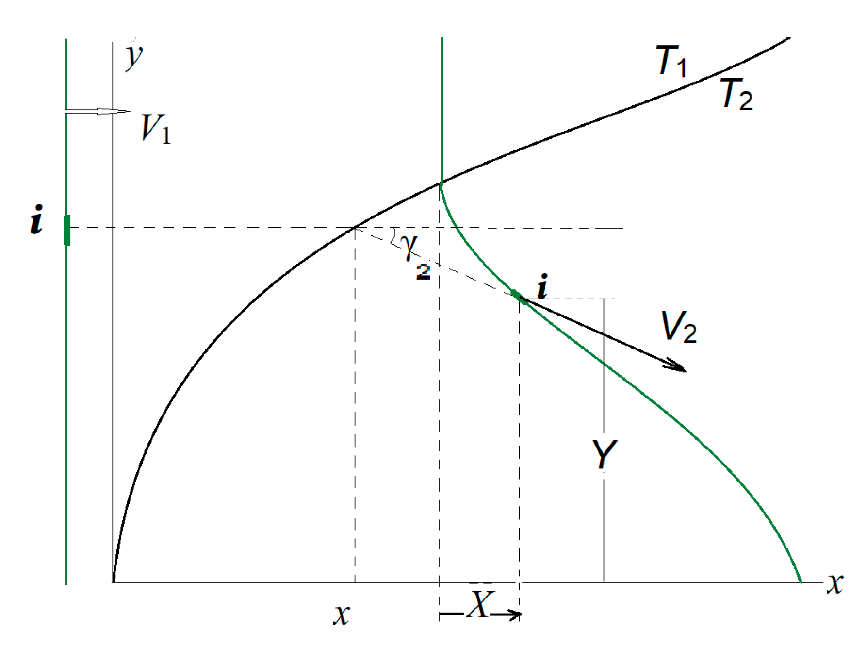
Figure 2.
A shock front interacting with the back interface (black solid curve) during its partial exiting into the cooler surrounding. It starts from the initial position (left green) followed with further front distortion (right green).
Figure 2.
A shock front interacting with the back interface (black solid curve) during its partial exiting into the cooler surrounding. It starts from the initial position (left green) followed with further front distortion (right green).
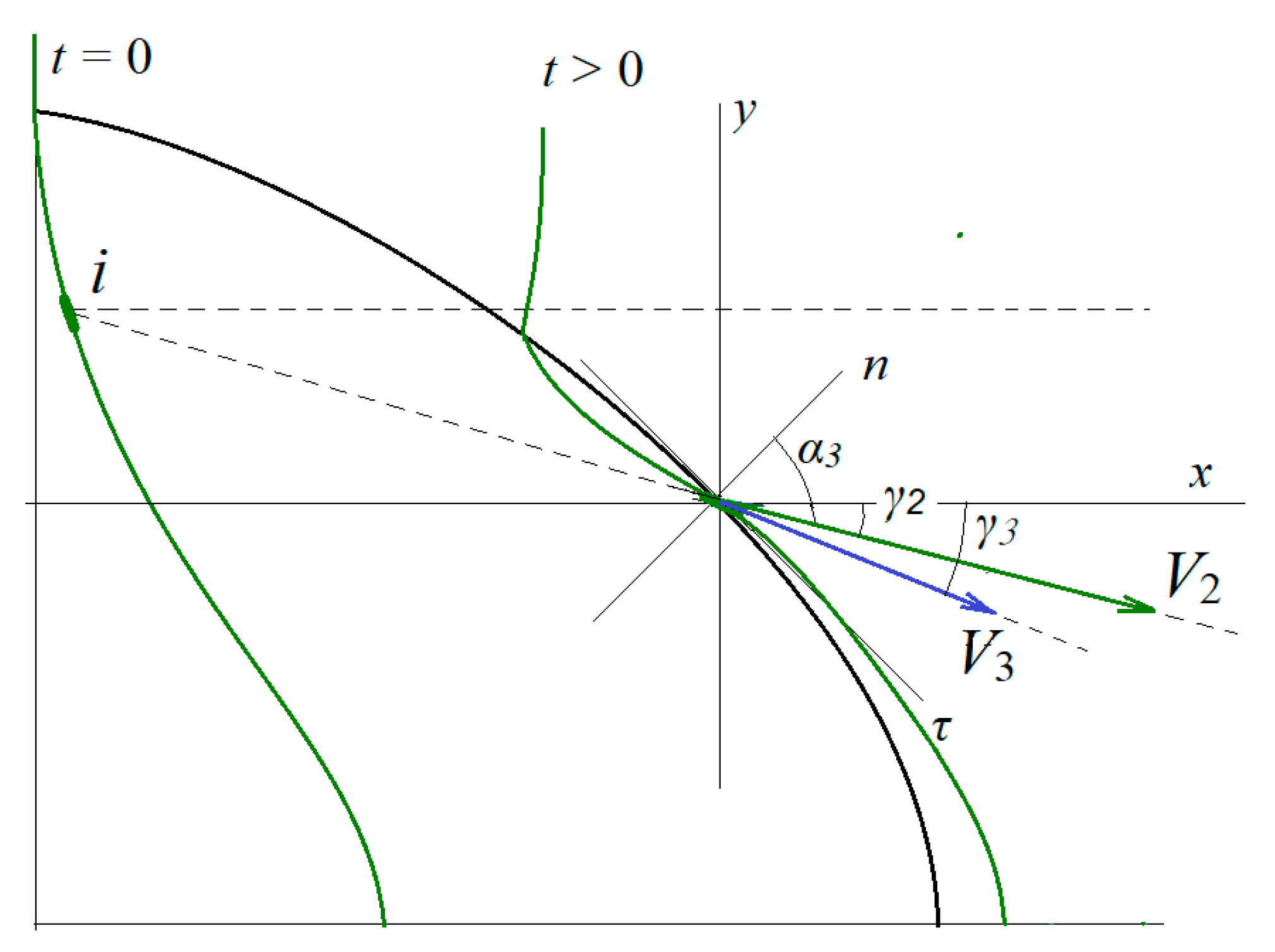
Figure 3.
Shock front modification as the result of its refraction at the back interface. A small element of the initial front with coordinates (xi, yi) ends up at the location (X3, Y3) at the moment of its emergence from the heated spot.
Figure 3.
Shock front modification as the result of its refraction at the back interface. A small element of the initial front with coordinates (xi, yi) ends up at the location (X3, Y3) at the moment of its emergence from the heated spot.
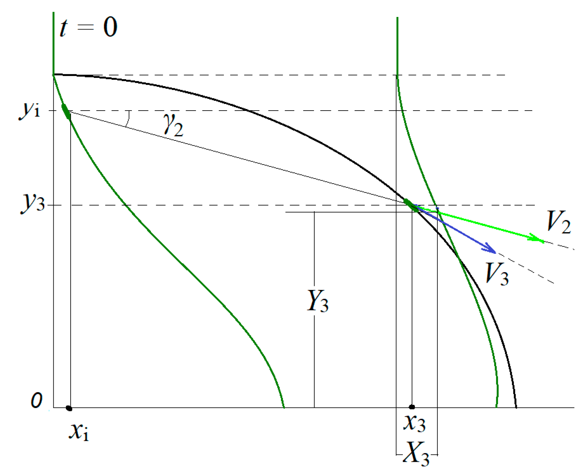
Figure 4.
(a) The normal component of the Mach number M2n vs M1n, at the entrance part of the interface. (b) The component M3n vs M2n at the back interface. Diatomic nitrogen at T1 = 300 K, T2 = 2000 K, M1 = 3.5, p = patm.
Figure 4.
(a) The normal component of the Mach number M2n vs M1n, at the entrance part of the interface. (b) The component M3n vs M2n at the back interface. Diatomic nitrogen at T1 = 300 K, T2 = 2000 K, M1 = 3.5, p = patm.
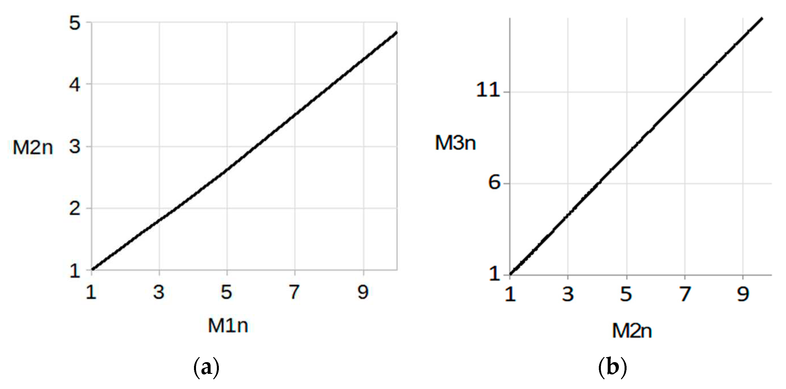
Figure 5.
Distortion of a shock front in (x,y) plane as it crosses a spherical hot spot, from left to right. The curves correspond to dimensionless times through the equal intervals of Δnτ = 0.2 for the first 6 curves, Δnb= 0.15 for the next three crossing the back interface, and Δnb= 0.3 for those propagating freely behind it. Diatomic nitrogen gas at T1=300 K, T2 = 2000 K, M1 = 3.5.
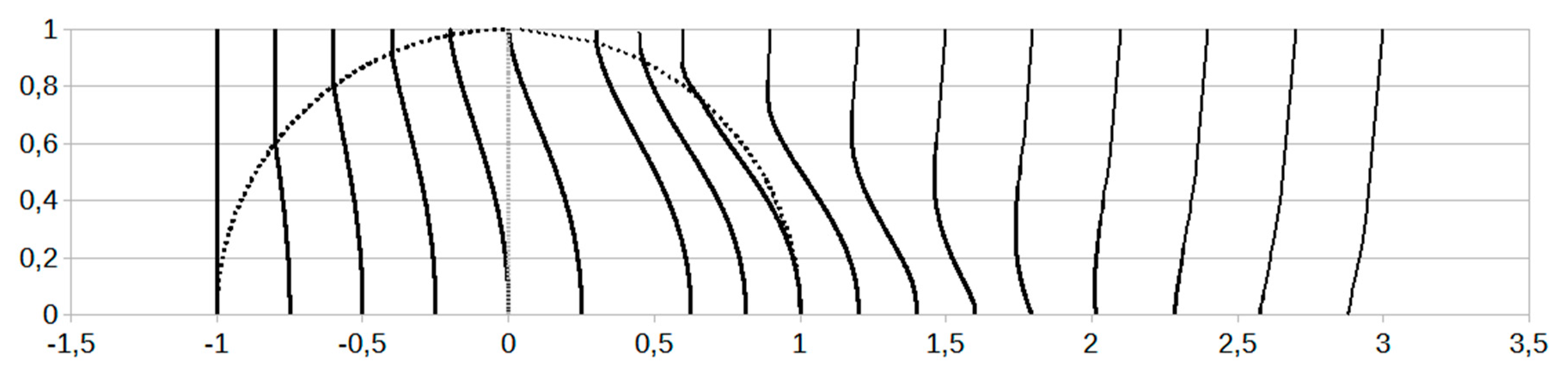
Figure 6.
Shock parameter distribution along the interface (its dimensionless coordinate y). (a) Refraction angles γ2° (dashed curve) and γ3° (solid). (b) Incidence angles α2° (dashed) and α3° (solid). (c) Shock velocity ratios, υ21 (dashed) and υ32 (solid). (d) Mach numbers M2 (dashed) and M3 (solid). (e) Shock velocity V3 normalized to V1. (f) V2y (dashed) and V3y (solid) components of the shock velocities. Diatomic nitrogen gas at T1 = 300 K, T2 = 2000 K, M1 = 3.5.

Figure 7.
The components of the deformation rate matrix ℜxx (graph a) and ℜxy (graph b) at the entrance of a spherical heated spot vs the dimensionless coordinate x/a. The shock and gas conditions are the same as in the previous figure. In both graphs, the time sequence is from lower to upper curve and each curve corresponds to a dimensionless time starting at nτ = 0.2 through equal intervals of Δnτ = 0.2.
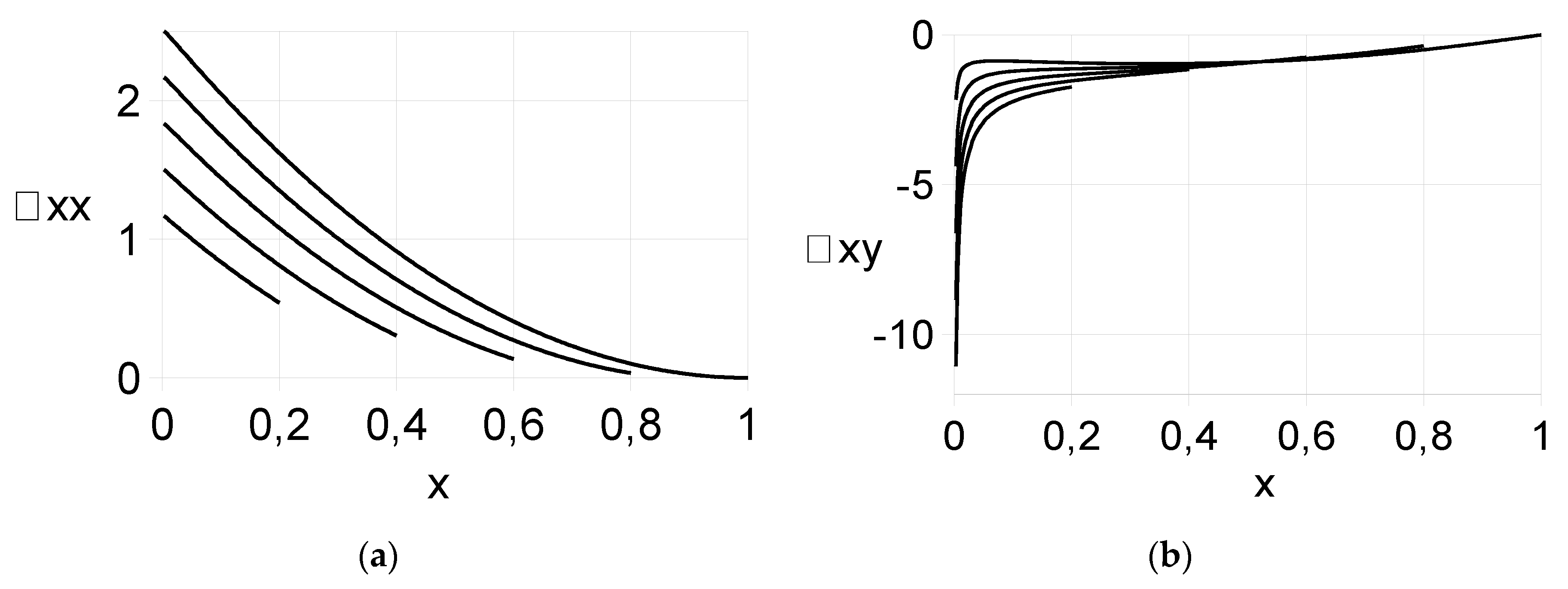
Figure 8.
The rate components ℜ(E)xx (graph a) and ℜ(E)xy (graph b) vs y3 at the exit from the spherical spot and behind it. The curves correspond to dimensionless times n3 between 0.2 and 1.8 through the equal intervals of 0.4. The time sequence is from lower to upper curve in graph (a), and from upper to lower in graph (b).
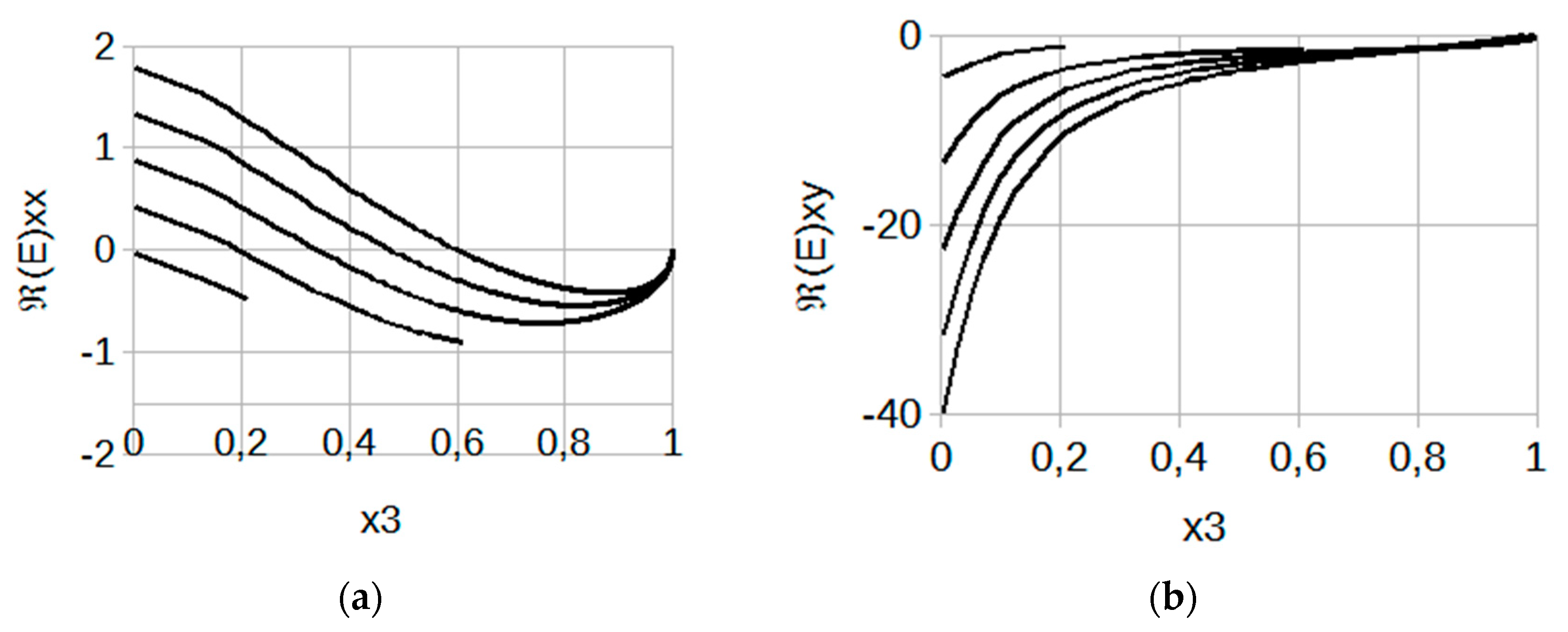
Figure 9.
Shock front distortion as it crosses a hot spot of an elliptical cross section oriented transversely, followed by its recovery after emergence from the spot. The fronts entering the spot correspond to times starting at nτ = 0.2 through the equal intervals of Δnτ = 0.2, for those exiting the spot Δnb = 0.1, and for the rest outside of the spot Δnb = 1.0. The profile coordinates are normalized to b, and b/a = 5/2. Diatomic nitrogen at T1=300 K, T2 = 2000 K, M1 = 3.5.
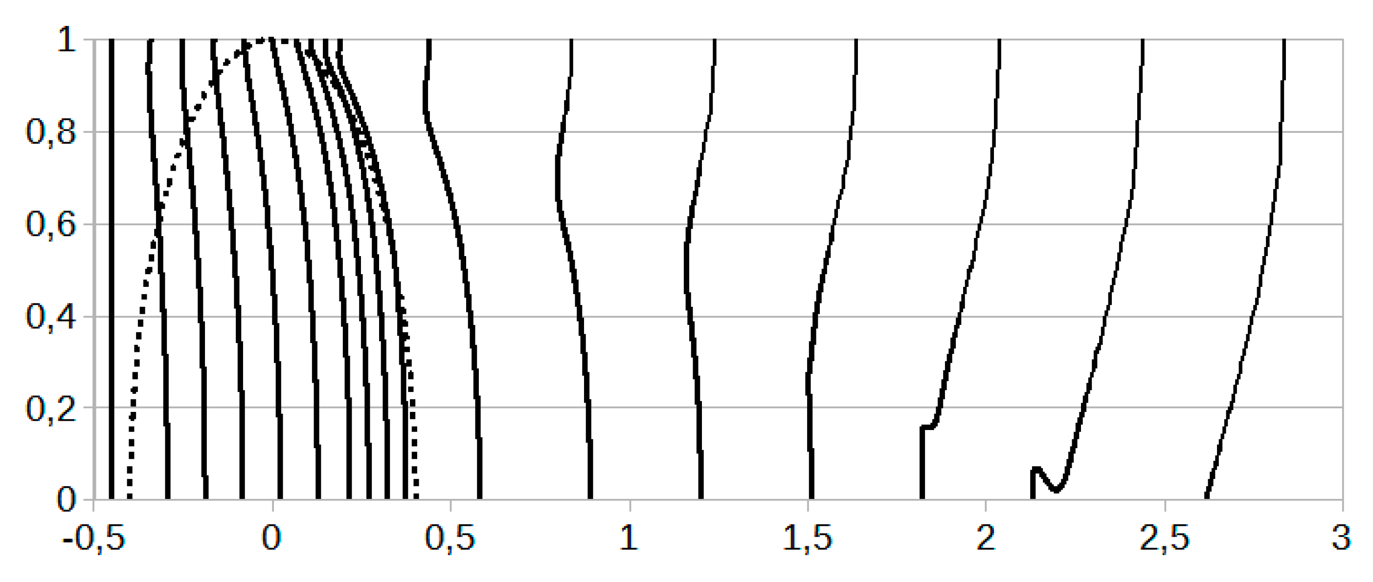
Figure 10.
Front distortion as the shock crosses a drop-like shaped heated spot. The profiles correspond to several instances of dimensionless time through the equal intervals of Δnτ = 0.2 (first 6 curves at the entrance), Δnb = 0.15 (next 4 fronts at the exit), and Δnb = 0.25 for those moving free behind the spot. The profile coordinates are normalized to b, and b/a3 = 5/7. Diatomic nitrogen at T1 = 300 K, T2 = 2000 K, M1 = 3.5.
Disclaimer/Publisher’s Note: The statements, opinions and data contained in all publications are solely those of the individual author(s) and contributor(s) and not of MDPI and/or the editor(s). MDPI and/or the editor(s) disclaim responsibility for any injury to people or property resulting from any ideas, methods, instructions or products referred to in the content. |
© 2023 by the authors. Licensee MDPI, Basel, Switzerland. This article is an open access article distributed under the terms and conditions of the Creative Commons Attribution (CC BY) license (http://creativecommons.org/licenses/by/4.0/).
Copyright: This open access article is published under a Creative Commons CC BY 4.0 license, which permit the free download, distribution, and reuse, provided that the author and preprint are cited in any reuse.


