
Submitted:
07 November 2023
Posted:
08 November 2023
You are already at the latest version
Abstract
As the general acceptance of fiber-reinforced polymer (FRP) in the concrete construction industry continues to rise, it is increasingly imperative that the crack width of FRP reinforced concrete members of pavement and girder be predicted with good accuracy due to strengthening of RC pavement, slabs or beams structures using FRP is known to control crack width. However, no specific provisions are provided by most international design codes for predicting crack width in FRP reinforced concrete flexure members. In this paper, five formulas for predicting the crack width for FRP reinforced structures are derived from three common computational theories which including statistical method, comprehensive theory, and bond-slip theory. The formula of statistical method is simplest, but the parameters depend on much sample data. The comprehensive and slippage theory based on semi-empirical statistical crack spacing are obtained through the calculation of non-uniformity coefficient of strain. The comprehensive and slippage theory based on semi-empirical axial force balance are obtained through the calculation of tensile reinforcement factor. The comparative analysis of performance of five formulas is carried out. The results indicate that the formula from comprehensive theory based on semi-empirical statistical crack spacing is recommended for predicting the crack width of FRP reinforced concrete flexural structure.
Keywords:
highway structure
; concrete pavement
; concrete girder
; crack width
; FRP
; cracks spacing
; comprehensive theory
1. Introduction
Crack control is an important serviceability criterion in the design of RC highway structures including girder and pavement structure. Cracking of concrete is related to its limited tensile deformation capacity, and is usually expected to develop in RC members under service loads during the lifetime of the structure. However, there should be some control over the width and distribution of structural cracks in order to maintain the aesthetics of the structure, protect the internal steel reinforcement especially when subjected to aggressive environments, and reduce the risk of debonding of the FRP external reinforcement.
The application of externally bonded FRP reinforcements for the flexural strengthening of RC members is becoming popular worldwide. The purpose of FRP strengthening is to increase the ultimate capacity or improve service conditions. Generally, RC members strengthened with FRP laminates have smaller and closely spaced cracks compared with the unstrengthened beams and pavement structure, either considering the same service load or considering the same tension level in the steel. This is due to the additional tension stiffening of the reinforcement that reduces the crack spacing.
The large number of experimental tests on RC elements strengthened by externally bonded FRP laminates and sheets available in the literature focused on studying the flexural behavior at ultimate conditions [1–13]. Only limited studies dealt with predicting the crack width of FRP-strengthened beams [14–17]. In this paper, formulas for predicting the crack width in flexure RC members from leading international codes and design guidelines are presented. Five formulas for predicting the crack width for FRP reinforced structures are derived from three common computational theories which including statistical method, comprehensive theory, and bond-slip theory. The resulting prediction formulas are evaluated by comparison with the results from the conducted experimental data. In addition, the recommended formula for predicting the crack width for FRP reinforced structures is given.
2. Conventional methods
At present, there are many methods for calculating the width of structural cracks in different codes. But there is rarely special recommended formula for predicting the crack width for FRP reinforced structures. The conventional solution is to make FRP equivalent to steel bar through elastic modulus ratio.
A total of 98 components from references [17–29] were selected and a comparison of methods form eight specifications is carried out. The details of predicting the crack width for FRP reinforced structures form above references are shown in Table 1. The calculation results of predicting the crack width for FRP reinforced structures from different codes are shown in Figure 1.

Table 1.
Collection of different test results.
| Ref. | Test number | Crack width | Ref. | Test number | Crack width | Ref. | Test number | Crack width |
|---|---|---|---|---|---|---|---|---|
| Huang [17] |
1 | 0.3 | Wu [18] |
one layer -1 | 0.07 | Feng [20] |
BF I-2-1 | 0.10 |
| 2 | 0.3 | one layer -2 | 0.18 | BF I -3-1 | 0.14 | |||
| 4 | 0.3 | three layer -1 | 0.05 | BF I -4-1 | 0.11 | |||
| 6 | 0.3 | three layer -2 | 0.09 | BF I -2-2 | 0.24 | |||
| 8 | 0.3 | You [19] |
CFRP-1-34 | 0.18 | BF I -3-2 | 0.20 | ||
| 9 | 0.3 | CFRP-2-48 | 0.17 | BF I -4-2 | 0.16 | |||
| 13 | 0.3 | CFRP-3-53 | 0.14 | BF I -2-3 | 0.40 | |||
| 15 | 0.3 | GFRP-1-31 | 0.19 | BF I -3-3 | 0.27 | |||
| Wu [21] |
CL25-2C-8.4 | 0.06 | GFRP-2-37 | 0.1 | BF I -4-3 | 0.21 | ||
| CL25-2G-8.5 | 0.14 | GFRP-3-44 | 0.1 | Hu [24] |
BM0 | 0.09 | ||
| CL25-2C-12 | 0.16 | Ahmed [23] |
ST-S-1 | 0.14 | Zhang [22] |
JL1-30 | 0.05 | |
| CL25-2G-10.8 | 0.22 | ST-S-2 | 0.23 | JL2-30 | 0.05 | |||
| Liew [26] |
AB-G1-1m | 0.21 | Alam [25] |
C1 | 0.16 | JL3-30 | 0.05 | |
| AB-G1-3m | 0.2 | C2 | 0.14 | YL1-30 | 0.18 | |||
| AB-G1-6m | 0.18 | C3 | 0.28 | YL2-30 | 0.10 | |||
| AB-G1-1y | 0.17 | Monica [27] |
CFB_01_60 | 0.1 | JL1-40 | 0.08 | ||
| AB-G2-1m | 0.13 | AFB_01_60 | 0.1 | JL2-40 | 0.05 | |||
| AB-G2-3m | 0.09 | CFB_02_60 | 0.06 | JL3-40 | 0.08 | |||
| AB-G2-6m | 0.07 | AFB_02_60 | 0.1 | YL1-40 | 0.23 | |||
| AB-G2-1y | 0.1 | GFB_02_60 | 0.1 | YL2-40 | 0.13 | |||
| OB-G1-1m | 0.25 | CFB_01_100 | 0.4 | JL1-50 | 0.10 | |||
| OB-G1-3m | 0.17 | AFB_01_100 | 0.4 | JL2-50 | 0.10 | |||
| OB-G1-6m | 0.1 | CFB_02_100 | 0.15 | JL3-50 | 0.10 | |||
| OB-G1-9m | 0.15 | AFB_02_100 | 0.2 | YL1-50 | 0.25 | |||
| OB-G1-1y | 0.11 | GFB_02_100 | 0.2 | YL2-50 | 0.15 | |||
| CB-G1-6m | 0.18 | Abdulaziz [28] |
PL-1-0.6 | 0.24 | Hua [29] |
CW1 | 0.35 | |
| CB-G1-1y | 0.09 | PL-1-0.3 | 0.35 | CW2 | 0.38 | |||
| OB-G2-1m | 0.18 | PL-2-0.6 | 0.36 | CW3 | 0.25 | |||
| OB-G2-3m | 0.1 | S-3-0.2 | 0.39 | DW1 | 0.43 | |||
| OB-G2-6m | 0.16 | PL-1-0.6-1 | 0.2 | DW2 | 0.41 | |||
| OB-G2-9m | 0.14 | PL-1-0.3-1 | 0.2 | DW3 | 0.3 | |||
| OB-G2-1y | 0.08 | PL-2-0.6-1 | 0.25 | / | ||||
| CB-G2-6m | 0.08 | S-3-0.2-1 | 0.24 | |||||
| CB-G2-1y | 0.06 | / | ||||||
The Figure 1 shows that the conventional calculation methods of codes are not very suitable to FRP reinforced structure. The results of predicting the crack width for FRP reinforced structures have a highly discrete feature. The reason is that calculations of crack width are used semi-empirical models and many parameters are derived from the test or statistical results of actual structure without FRP. Therefore, it is necessary to investigate a reasonable method of predict the crack width for FRP reinforcement structure.
3. Statistical methods
Statistical analysis is a common method to deal with crack problems. It is assumed that the total crack width is consisted of two parts which is initial crack width before reinforcement and additional crack width. The total width w can be written as
where w0 is initial crack width and Δw is additional crack width.
w=w0+Δw
The initial crack width is given by
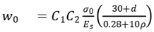 where σ0 is stress of steel bar, ρ is steel ration, Es is elastic modulus of steel bar, d is diameter, C1 is shape factor of steel bar, C2 is structural stress characteristic coefficient.
In a similar way, it can be assumed that the value of additional crack width has the same expression as
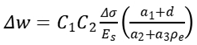 where ρe is equivalent ration after FRP reinforcement, Δσ is increased stress after FRP reinforcement, a1, a2 and a3 are parameters to be determined.
The parameters zexp and z are defined as follows

 where wexp is the measured crack width from experiments.
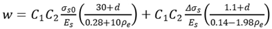
The parameters a1, a2, and a3 are the most appropriate values that minimize the formula . The fitting parameters are determined by the data measured form the references. The final formula is as follows
4. Semi-empirical theory based on statistical crack interval
4.1. Crack interval based on statistical approaches
Above result has shown that there was a positive correlation between crack spacing and cover thickness, and between crack spacing and ration of reinforcement diameter to reinforcement ratio. It is assumed that the crack spacing can be a formula as follows
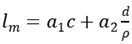 where c is thickness of concrete cover, a1 and a2 are the calculation parameters that can be obtained by least-squares fitting procedure through the experimental data, and a1 is 1.46, and a2 is 0.03.
4.2. Non-uniformity coefficient of strain
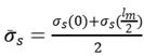
Concrete is not ideal homogeneous material and the problem will be very complicated if the stress is too much focused at each point. Using average stress is an efficient method. Non-uniformity coefficient of strain of reinforced concrete structure can be written as
 where is average strain of reinforcement, is steel strain of fracture section.
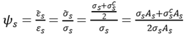
Similarly, non-uniformity coefficient of strain of FRP concrete was defined by the following expression.
 where is average strain of FRP, is FRP strain of fracture section.
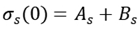
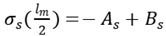
For reinforced concrete members, the stress of steel bar is very high at the crack, going down to both sides. Because of the characteristic of bonding failure, the bonding stress is zero at the crack. So it is assumed that the stress of steel bar between two cracks can be written as
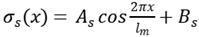 where lm is crack spacing, x is the distance from the crack to any point between two cracks, As and Bs are calculation parameters.
Average stress of steel bar between cracks can be written as
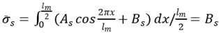
And
So
Obtain
In the same way, it can be drawn for FRP structure
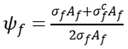 where is stress of FRP between two cracks.
The tensile force between the cracks is shown in Figure 3.
According to the principle of axial force balance, there is a formula as
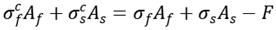
There is an assumption
Substitute Eq. (17) to Eq. (18), obtain
There is an equilibrium condition
So
4.3. Calculation of fracture width by comprehensive theory
There is an assumption that the crack is a triangular shape, and the width reaches maximum on the concrete surface and zero at the neutral axis, which is shown in Figure 4.
The crack width at the bottom of the beam and pavement structure consists of two parts, CD and DE, where , . The average width of crack can be written as
 where xc is concrete compression height, x is relative height of compression zone.
There is a relationship between compression height and relative height of compression zone for C50 concrete in normal structure where x=0.8 xc . The formula can be written as

The average width of crack can be written as
The maximum width of the crack can be written as
 where as is expanded coefficient that is determined by least square method.
4.4. Calculation of fracture width by slippage theory
Similar to reinforced concrete structure .It is assumed that the development of cracks is due to relative slippage between FRP and concrete on the bottom of the beam and the pavement structure.
The average width of crack can be written as

The maximum width of the crack can be written as
 where is expanded coefficient that is determined by least square method, the value of is assumed to be 1.04.
5. Semi-empirical theory based on bond stress theory
5.1. Crack spacing based on axial force balance
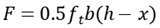
According to axial force balance theory in crack prediction, there is an equation that can be written as
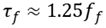
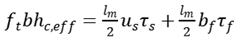 where is compressive strength of concrete, b is width of section, is effective tension height, and is bond stress of steel bar and FRP, and is perimeter of steel bar and FRP. And
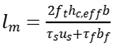

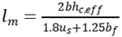
Crack spacing can be expressed as
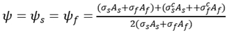
5.2. Tensile reinforcement factor ζ
When the tension of the reinforced concrete member beyond the specified limitation, the concrete is cracking. The cracking section of the concrete is out of work, but the concrete between cracks can still bear tension. Tensile reinforcement factor is as follows
 where M is bending moment caused by external load, Mcr is crack load, β is shape coefficient.
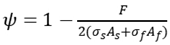
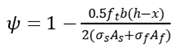
5.3. Calculation of fracture width by comprehensive theory
In the same way as described in section 3.3, the maximum width of the crack can be written as
 where as is expanded coefficient that is determined by least square method, the value of as is assumed to be 1.47.
5.4. Calculation of fracture width by slippage theory
In the same way as described in section 3.3, the maximum width of the crack can be written as
 where af is expanded coefficient that is determined by least square method, the value of af is assumed to be 1.41.
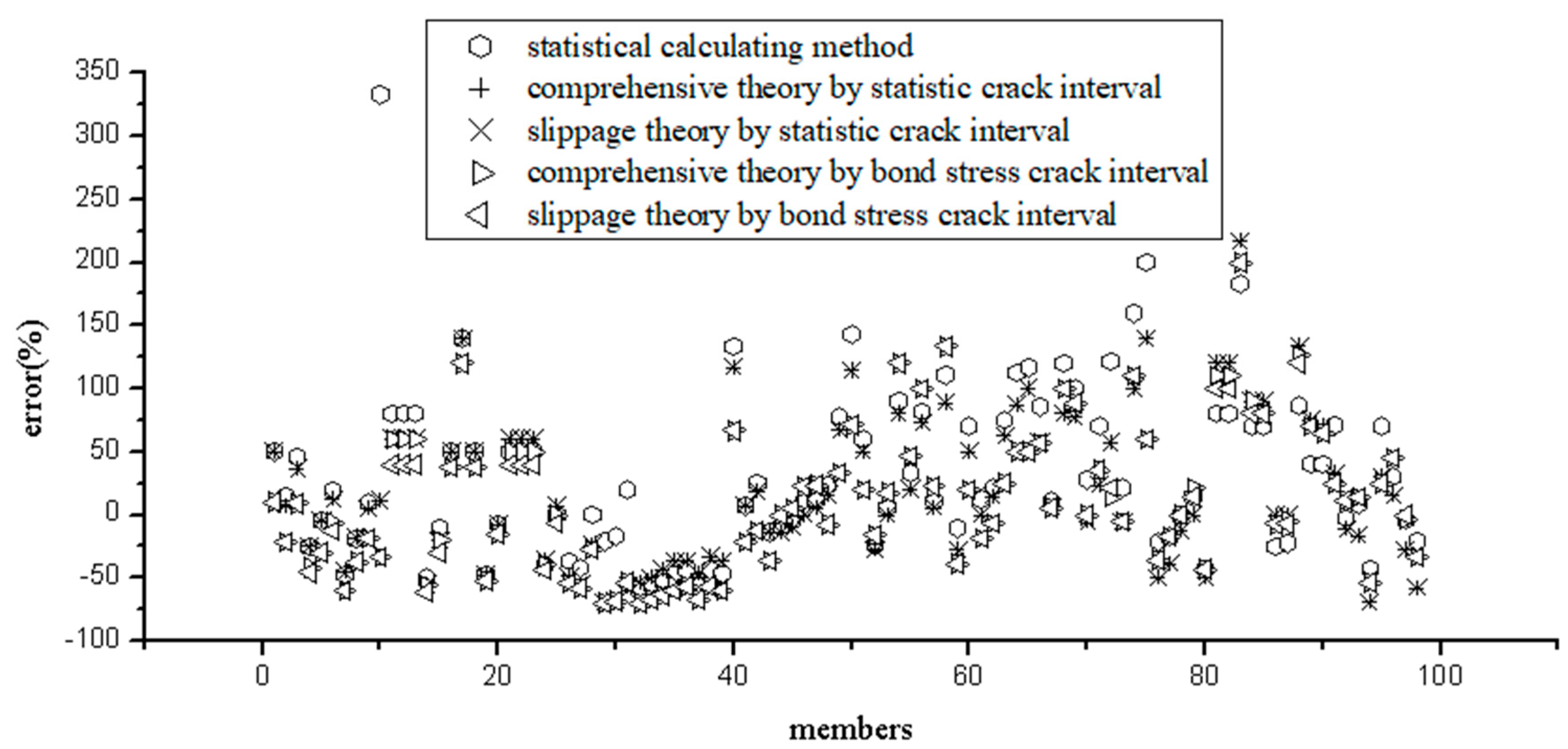
6. Comparison of different formulas
There are three computational theories of crack width in FRP structure, based on which five formulas are derived. These formulas are applied to the above model tests, the comparison and analysis of calculation results are shown in Figure 8. We can see from Figure 8 that (1) the results of different methods are very close except statistical calculating method; (2) distribution of errors is very similar, mostly concentrated at ±50 %. Although the statistical calculating method is the closest to the measured value, the calculation parameters will depend on the sample size, which not very accurate in theory, but just as a simple way to deal with the problem.
In general, the other four formulas are all available for predicting of crack width for FPR structure. Using trigonometric function to simulate the stress unevenness coefficient is more meaningful than axial force balance in point view of theory. Meanwhile, comprehensive theory covers more factors than slippage theory. Therefore, the equal (25) of prediction of crack width by comprehensive theory based on statistical crack interval is recommended as the most suitable calculation method.
7. Conclusions
This paper presents five different formulas based on three common theories which including statistical method, comprehensive theory, and bond-slip theory. The calculating parameters in the formulas come from the test results of different resentences. The applicability performance of five formulas is compared. The following conclusions can be obtained.
(1) The statistical formula is the simplest, the advantage of which has less parameters and is easily applied to predict crack width in FRP reinforced concrete flexure members. However, different test results have great influence on its own formula parameters and the tests on FRP cracks are very limited. This method can only be used as a simple method to solve problems of cracking in FRP reinforced concrete flexure members.
(2) Analysis of crack spacing based on axial force balance is not very accurate in point view of theory because of ignoring the effect of force distance, so the formula based on which is also not very reasonable.
(3) Comprehensive and slippage theory are both widely used in codes or specifications all over the world. There are more calculation factors involved in comprehensive theory. Therefore, the proposed formula for predict crack width in FRP reinforced concrete flexure members is recommended. In brief, the method of comprehensive theory using statistical crack spacing is recommended in predicting crack width in FRP reinforced concrete flexure members.
Author Contributions
L.T., M.C., S.M., L.M., investigation; D.F., Z.Y., writing. All authors have read and agreed to the published version of the manuscript.
Funding
the Fundamental Research Funds for the Central Universities of China (Grant No. 310821161012), the Natural Science Foundation of Jiangsu Province (Grant No. BK20200793).
Data Availability Statement
The data used to support the findings of this study are available from the corresponding author upon request.
Acknowledgments
The authors would like to acknowledge the financial support provided by the Fundamental Research Funds for the Central Universities of China under Grant 310821161012. The help of engineers and technicians in the Key Laboratory of Bridge Detection Reinforcement Technology Ministry of Communications of Chang’an University is highly appreciated. The authors wish to express their sincere thanks to the Natural Science Foundation of Jiangsu Province (Grant No. BK20200793).These supports are gratefully acknowledged. The valuable comments of the anonymous reviewers of the paper are also acknowledged.
Conflicts of Interest
The authors declare no conflict of interest.
References
- Colombi P and G Fava. Experimental study on the fatigue behaviour of cracked steel beams repaired with CFRP plates [J]. Engineering Fracture Mechanics, 2015, 145: 128-142. [CrossRef]
- Ferdous W, et al. Modular assembly of water-retaining walls using GFRP hollow profiles: Components and connection performance [J]. Composite Structures, 2018. 194: 1-11. [CrossRef]
- Gholampour A and Ozbakkaloglu T. Behavior of steel fiber-reinforced concrete-filled FRP tube columns: Experimental results and a finite element model [J]. Composite Structures, 2018. 194: 252-262. [CrossRef]
- Haddad R H and Obaidat Y T. A nonlinear finite element model for shear deficient heat-damaged concrete beams repaired using NSM CFRP strips [J]. Construction and Building Materials, 2018. 170:314-325. [CrossRef]
- Ge W,Zhang J,Cao D,et al. Flexural behaviors of hybrid concrete beams reinforced with BFRP bars and steel bars [J].Construction and Building Materials, 2015, 87: 28-37. [CrossRef]
- Alsayed S H. Flexural behavior of concrete beams reinforced with GFRP bars [J]. Cement and Concrete Composites, 2010, 20(5):460-469. [CrossRef]
- Pecce M, Manfredi G. Cosenza E. Experimental response and code models of GFRP RC beams in bending [J]. Journal of Composites for Construction,2000,4(4):182-190. [CrossRef]
- Rafi M M,Nadjai A,Ali F,et al. Aspects of behavior of CFRP reinforced concrete beams in bending [J].Construction and Building Materials, 2008, 22( 3) : 277-285. [CrossRef]
- Piscesa B, M.M. Attard, and Samani AmK. 3D Finite element modeling of circular reinforced concrete columns confined with FRP using a plasticity based formulation [J]. Composite Structures, 2018. 194: 478-493. [CrossRef]
- Schnerch, D, et al. Proposed design guidelines for strengthening of steel bridges with FRP materials [J]. Construction and Building Materials, 2007. 21(5):1001-1010. [CrossRef]
- Sun W, et al. Impacts of configurations on the strength of FRP anchors [J]. Composite Structures, 2018. 194:126-135. [CrossRef]
- Mias C, Torres L, Guadagnini M, et al. Short and long-term cracking behavior of GFRP reinforced concrete beams [J]. Composites Part B Engineering, 2015, 77:223-231. [CrossRef]
- Tomlinson D, Fam A. Performance of concrete beams reinforced with basalt FRP for flexure and shear [J]. Journal of Composites for Construction, 2014, 19(2):04014036. [CrossRef]
- Aljabar N J, Zhao X L, Al-Mahaidi R, et al. Effect of crack orientation on fatigue behavior of CFRP-strengthened steel plates [J]. Composite Structures, 2016, 152:295-305. [CrossRef]
- Cornetti P, Corrado M, Lorenzis L D, et al. An analytical cohesive crack modeling approach to the edge debonding failure of FRP-plated beams [J]. International Journal of Solids & Structures, 2015, 53(2):92-106. [CrossRef]
- Zheng B and Dawood M. Fatigue crack growth analysis of steel elements reinforced with shape memory alloy (SMA)/fiber reinforced polymer (FRP) composite patches [J]. Composite Structures, 2017. 164: 158-169. [CrossRef]
- Huang, H. Experimental study on normal section bearing capacity of reinforced concrete beam reinforced with carbon fiber sheet [D]. Hunan University, 2001.
- Wu G, An L, Lv Z. study on the flexural reinforcement of reinforced concrete beams with carbon fiber cloth [J]. Building structure, 2000, 30(7):3-6.
- You P, Wang Y, Zhang C. A method for calculating the crack resistance and crack width of a unidirectional plate reinforced with fiber composite materials [J]. 2014, 32(6):100-103.
- Feng J. Calculation of Crack Width and Stiffness of Reinforced Concrete Beams Strengthened with CFRP [D]. Zhengzhou University, 2013.
- Wu J. Experimental study on RC beam strengthened with externally bonded fiber reinforced polymer sheets [D]. Hunan University, 2005.
- Zhang D. Behavior of concrete members strengthened with carbon fiber reinforced plastic sheets [D]. Dalian University of Technology, 2016.
- El-Sayed A K, Al-Zaid R A, Al-Negheimish A I, et al. Long-term behavior of wide shallow RC beams strengthened with externally bonded CFRP plates [J]. Construction & Building Materials, 2014, 51(4):473-483. [CrossRef]
- Hu K, Yue Q, Ye L, et al. Study on bending performance of concrete bridge deck strengthened with carbon fiber cloth [J]. Building Structure, 2000,30(7):44-48.
- Alam M A. Experimental Investigations on U- and L-Shaped End Anchored CFRP Laminate Strengthened Reinforced Concrete Beams [J]. Arabian Journal for Science & Engineering, 2012, 37(4):905-919.
- Liew Y S. Durability of fiber reinforced polymer composites under tropical climate [D]. National University of Singapore, 2003.
- Garcez M, Meneghetti L, Silva Filho L C P D. Structural Performance of RC Beams Poststrengthened with Carbon, Aramid, and Glass FRP Systems [J]. Journal of Composites for Construction, 2008, 12(5):522-530. [CrossRef]
- Abdulaziz I, Al-Negheimish, Ahmed K. EI-Sayed, Rajeh A. Al-Zaid, et al. behavior of wide shallow RC beams strengthened with CFRP reinforcement [J]. Journal of Composites for Construction, 2012, 16(4):418-429. [CrossRef]
- Hua Ming. Flexural stiffness and crack widths of rectangular reinforced concrete beams strengthened with externally bonded CFRP sheets [D]. Southeast university, 2006.
- Code for Design of highway Reinforced Concrete and Prestressed Concrete Bridges and Culverts [S]. JTG D62-2004.
- Code for Design on Reinforced and Prestressed Concrete Structure of Railway Bridge and Culvert [S]. TB 10002.3-2005.
- Design Code for Hydraulic Concrete Structures [S]. SL 191-2008.
- Design Specification for Hydraulic Concrete Structures [S]. DL/T 5057-2009.
- CEB-FIP model code 1990 [S].
- EN.1992-1-1. Eurocode 2: Design of Concrete Structures - Part 1-1: General Rules and Rules for Buildings [S].
- Fib Bulletin 14(2001), FRP as externally bonded reinforcement of RC structures [S]: basis of design and safety concept. TG9.3 2001.
- Code for Design of Strengthening Concrete Structure [S]. GB 50367-2013.
Figure 1.
Comparison of different specifications and test results.
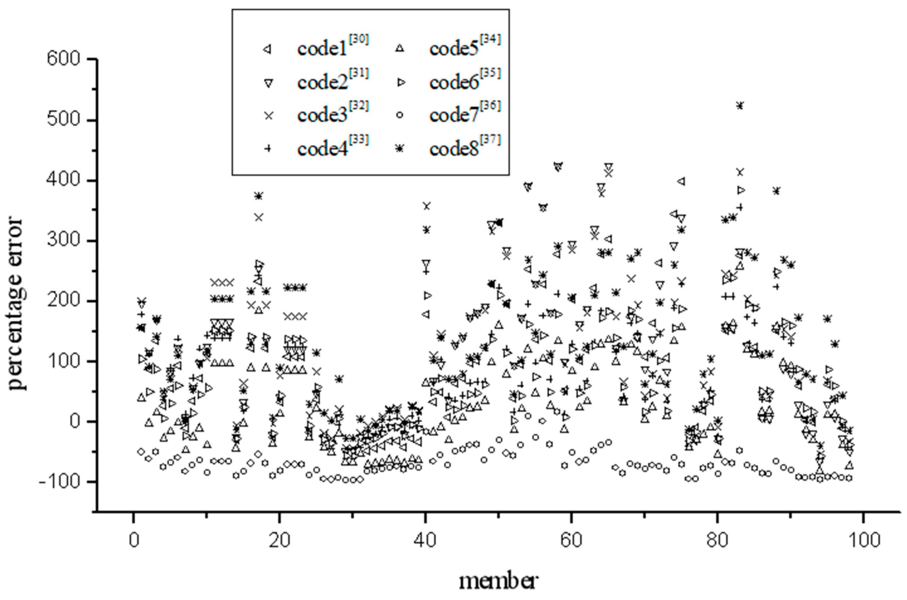
Figure 2.
Comparison between statistical method and measured value of experiment.
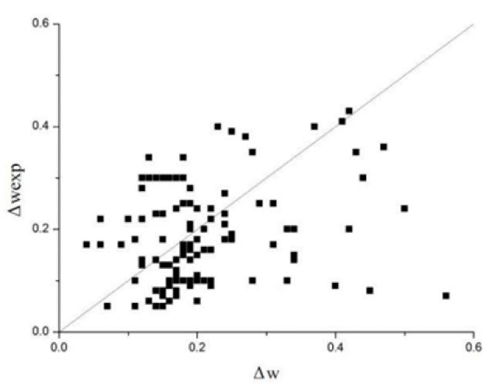
Figure 3.
The tensile force between the cracks.
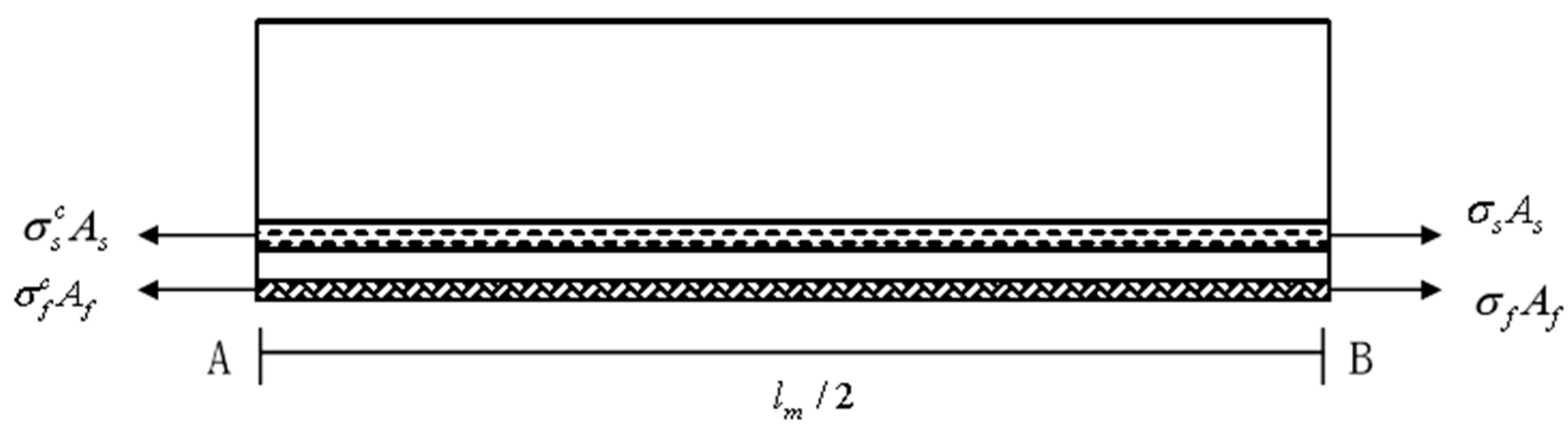
Figure 4.
Crack development diagram.
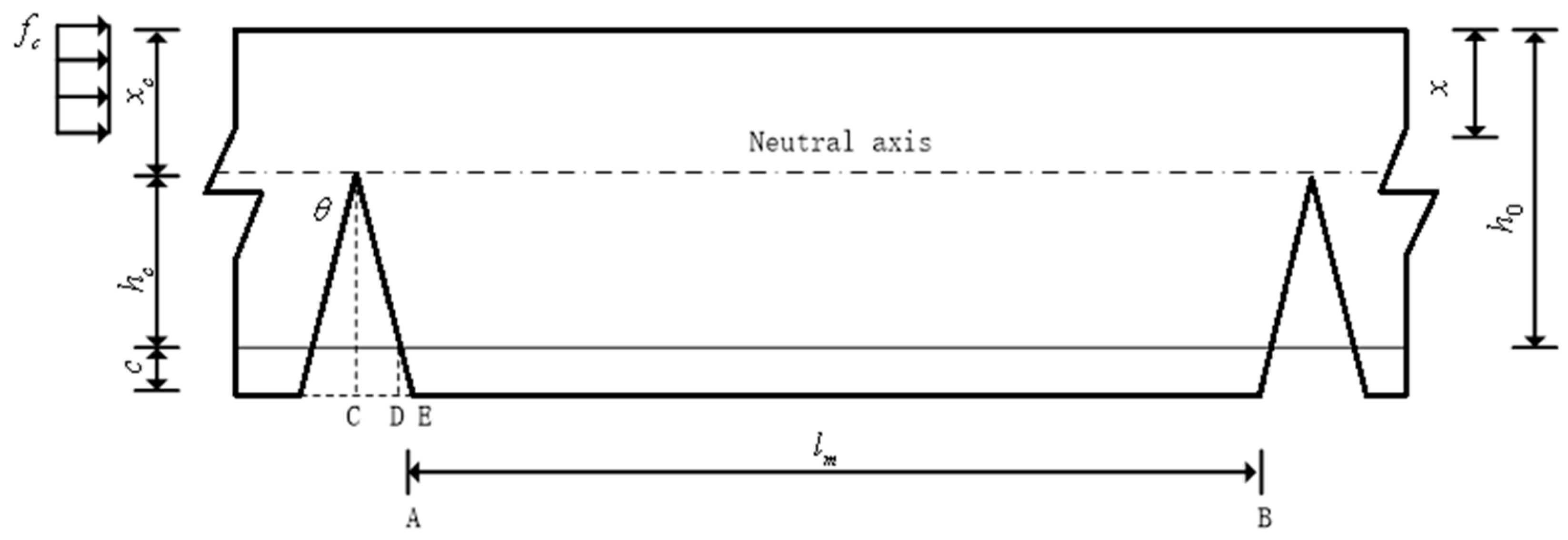
Figure 5.
Comparison between calculated and measured value of experiment.
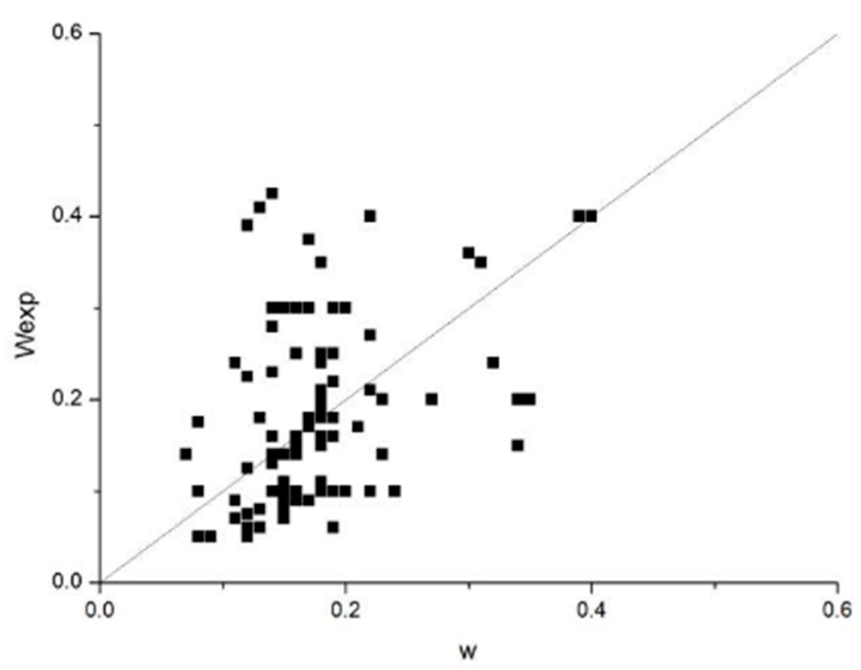
Figure 6.
Comparison between calculated and measured value of experiment.
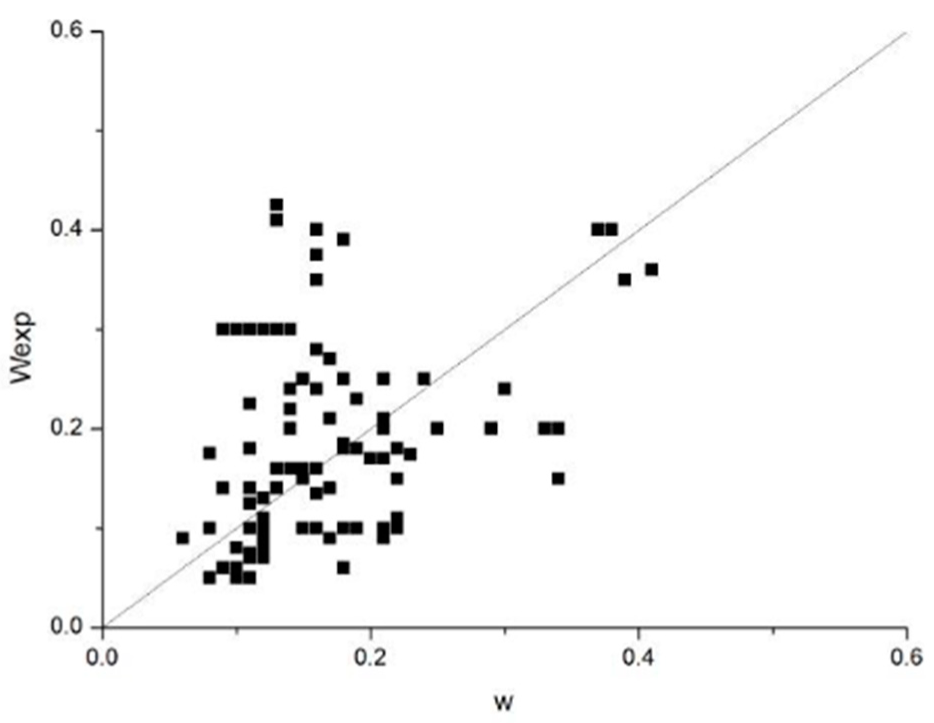
Figure 7.
Comparison between calculated and measured value of experiment.
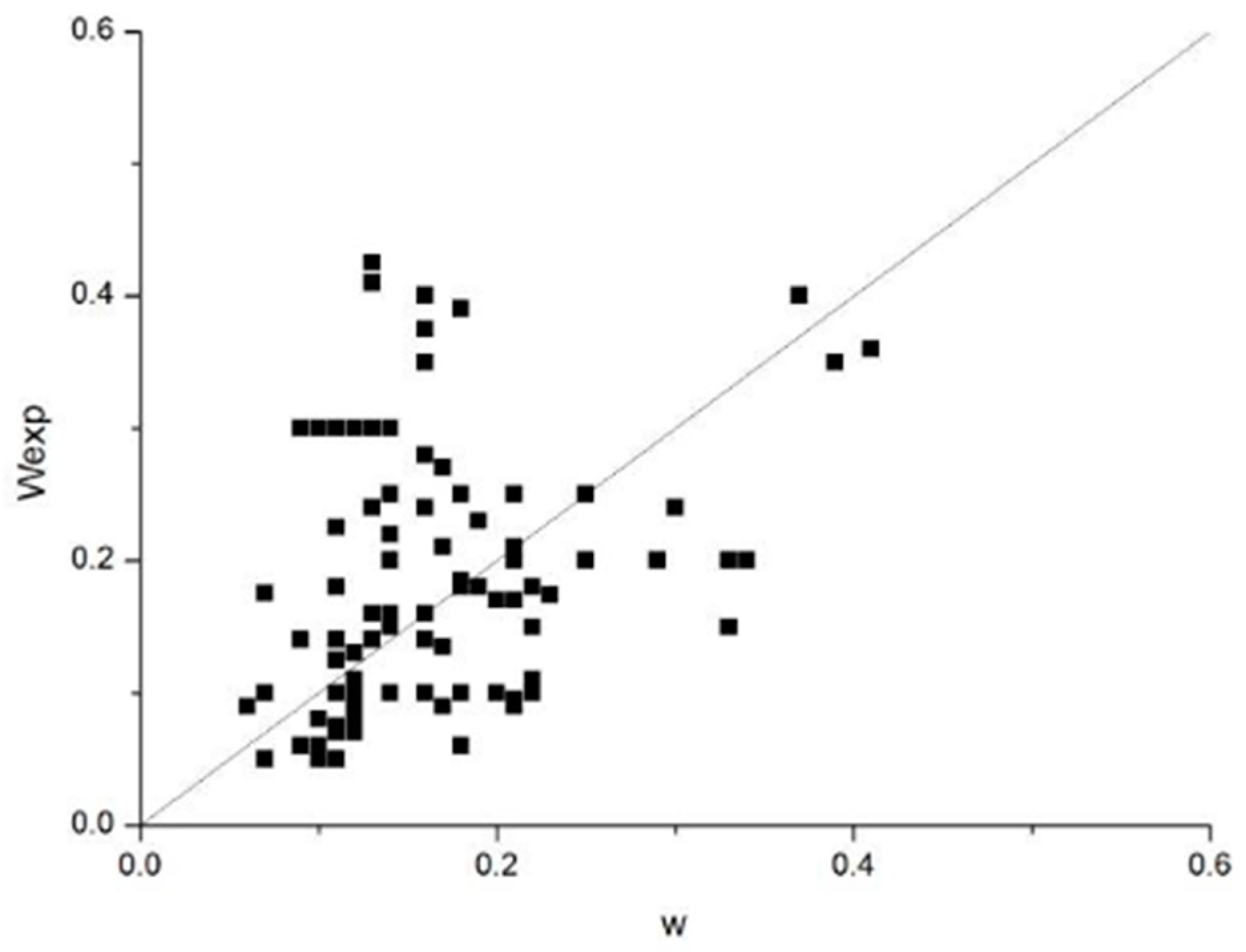
Figure 8.
Comparative analysis of different formulas.
Disclaimer/Publisher’s Note: The statements, opinions and data contained in all publications are solely those of the individual author(s) and contributor(s) and not of MDPI and/or the editor(s). MDPI and/or the editor(s) disclaim responsibility for any injury to people or property resulting from any ideas, methods, instructions or products referred to in the content. |
© 2023 by the authors. Licensee MDPI, Basel, Switzerland. This article is an open access article distributed under the terms and conditions of the Creative Commons Attribution (CC BY) license (http://creativecommons.org/licenses/by/4.0/).
Copyright: This open access article is published under a Creative Commons CC BY 4.0 license, which permit the free download, distribution, and reuse, provided that the author and preprint are cited in any reuse.


