
Submitted:
25 October 2023
Posted:
26 October 2023
You are already at the latest version
Abstract
This article aims to assess, discuss and analyze the disturbances caused by electromagnetic field (EMF) noise of medical devices used nearby living tissues, as well as the corresponding functional control via the electromagnetic compatibility (EMC) of these devices. These are minimally invasive and non-ionizing devices allowing various healthcare actions involving monitoring, assistance, diagnosis and image-guided medical interventions. Following to an introduction of the main items of the paper, the different imaging methodologies are conferred, accounting for their nature, functioning, employment condition and patient comfort and safety. Then the magnetic resonance imaging (MRI) components and their fields, the consequential MRI-compatibility concept and possible image artifacts are detailed and analyzed. Next, the MRI-assisted robotic treatments, the possible robotic external matter introductions in the imager, the features of MRI-compatible materials and the conformity control of MRI-compatibility, are analyzed and conferred. Afterward, the embedded, wearable and detachable medical devices, their EMF perturbation control and their necessary shielding protection technologies are presented and analyzed. Then, the EMC control procedure, the EMF governing equations, the body numerical virtual models, are conferred and reviewed. A qualitative methodology, case study, simple example illustrating the mentioned methodology is presented. The last Section of the paper discussed potential details and expansions of the different notions conferred in the paper, in the perspective of monitoring the disturbances due to EMF noise of medical devices working near living tissues.
Keywords:
EMF noise perturbation
; functional control
; EMC analysis
; devices working close to tissues
; monitoring
; assistance
; diagnosis
; image-guided interventions
; onboard devices
1. Introduction
Electromagnetic fields (EMFs) are used in many everyday equipment. They reflect wide ranges of force and frequency. The environment close to the EMF source devices is subject to their exposure. Unwanted exposure to such fields can cause different types of disturbances and disorders in various areas. One of the most concerned areas is health safety. In this case, the disorder could directly involve body tissues or healthcare diagnostic, detection and intervention devices. Regarding EMF exposure of tissues, most of the affected source devices are characterized by significant stray fields, e.g. wireless devices. Such direct EMF exposure of living tissues can cause different biological effects [1- 6]. The other effect of EMF exposure on health safety is related to medical devices. Such exposure can disrupt several types of health devices. The devices most affected by health problems are those working near body tissues. Two important categories of devices are concerned. The first concerns imaging diagnostic procedures and image-assisted robotic interventions [7- 13]. In such a case, disturbances due to EMF noise mainly concern universal non-ionizing procedures using MRI. The second category concerns body onboard embedded and wearable devices [14-18].
MRI as a diagnostic tool could be disrupted due to its sensitivity to EMF noise. This imager is generally protected against exposure to external fields. However, EMF noise could be triggered due to the introduction of magnetic or conductive material inside or near the imager. This may occur due to objects inserted in the body under test. The consequences would be image artifacts disrupting the diagnosis [19-22]. Considering the case of MRI-assisted robotic interventions, which can be surgical or implanted treatment. These procedures mainly concern situations requiring movement or location control. Thus, the assistance concerned, offers a remarkable means of localization improving the result of medical treatment and allowing precise minimally invasive actions. In this case, the EMF noise disturbance could be, in addition to the body tested, due to the presence of robotic accessories and medical tools within the imager [23- 29].
The EMF noise perturbation of onboard devices is provoked by exposure to external fields (radiation). Embedded and portable devices are often used for ongoing medical assistance or for diagnostic and monitoring purposes. The case of wearable mechanisms corresponding to a passive programmed role as sensing functions, e.g. [30-32]. The wearable biosensors involved behave as non-intrusive tools allowing real-time monitoring of patients, providing sufficient data to establish their health status and can constitute a first diagnosis. Devices integrated into the body can be static passive for permanent monitoring e.g. [17] or active stimulating or assistive tools, e.g. [18]. All of these onboard tools enable diligent, personalized and tailored healthcare. Note that most of these devices may be concerned by the disturbances caused by the patient's body inside the MRI mentioned above.
The different functional disorders of devices due to EMF noise mentioned above should be evaluated and controlled. Thus, a routine of functional control could be practiced on these devices. The functional control at large verify the ability of a device to operate in a specific environment. In the case of EMFs, generally speaking, the increasing complexity and amplified practice of electronic tools have given rise to electromagnetic interference (EMI), which involves various signals emitted in an unsolicited manner. These can affect the operation of systems in a specific electromagnetic atmosphere, causing them to fail or reducing their performance. Indeed, EMI corresponds to the transmission of disturbing energy (noise) between two systems (source and receiver) via radiating and/or conductive tracks. Such noise can come from an artificial source (like radar or a cell phone) or a natural source (like lightning). Furthermore, the noise could be intrinsic to the system due to alterations of its physical characteristics (like effect of the insertion of external materials). Concerning EMI, the creation of an electromagnetically compatible atmosphere in relation to the affected system (receiver) allows it to regain its intended operation. Thus, EMC can be achieved to respond to EMI threats. Therefore, due to the different types of noise mentioned, the functional EMC control can be termed as verifying the ability of a device to function properly in its electromagnetic environment without interference with itself or other systems in that environment.
Consequently, the various functional disturbances of medical devices conferred above can be evaluated and controlled by an EMC analysis, e.g. [25, 27, 29]. This can be achieved by experimental means (where possible) or by using numerical modeling tools. Such an assessment in addition to functional control can assist in the redesign of disturbed devices, disturbing sources and introduced external materials. Additionally, EMC analysis enables shielding design with validity verification regarding sources and targets of disturbances [33].
The aim of this contribution is to evaluate, confer and analyze the disturbances due to EMF noise of medical devices working near living tissues and the corresponding functional EMC control of these devices. These are minimally invasive and non-ionizing devices enabling various healthcare treatments involving monitoring, assistance, diagnosis as well as image-guided medical interventions.
The second section of the article presents the different imaging methodologies, taking into account their nature, their operation, their conditions of use as well as the comfort and safety of patients. MRI components and their field characteristics will be analyzed. The resulting concept of MRI compatibility and possible image artifacts will be detailed and analyzed. The third section concerns MRI-assisted robotic treatments. The possible robotic introductions of external materials, the characteristics of MRI compatible materials and the conformity check of MRI compatibility will be analyzed and discussed. The fourth section concerns integrated, portable and detachable medical devices. In this framework, control of EMF disturbances will be conferred and the necessary shielding protection technologies will be presented and analyzed. In the fifth section, the EMC control procedure will be analyzed and discussed. The equations governing EMF and their application in EMC control will be illustrated. Digital virtual models of the body that can be involved in the actual representation of the operating area of medical devices will be discussed and reviewed. A simple qualitative methodology case study example illustrating the mentioned methodology will conclude this section. Section 6 addresses the discussion of potential extensions of the different notions mentioned in the article, with the perspective of monitoring disturbances due to EMF noise of medical devices working close to living tissues.
2. Imaging Methodologies
Various imaging techniques are used in healthcare treatments. The chosen option depends on several conditions related to the circumstances realized. Live tissue imaging involves soft tissues, bones, fluids, and air gaps. The most widespread techniques use X-rays, magnetic fields, ultrasound or radioactive drugs (positron emission, gamma rays, etc.). The corresponding imagers are each relatively adapted to a specific case. Apart from magnetic and ultrasound imagers, the others are subject to ionizing radiation. These tools can be used for diagnostic purposes or therapeutic assistance. In conventional diagnostic imaging, patient exposure is short-term, posing no risk to any imager. On the other hand, persistent exposures such as e.g. assisted treatments infer taking into account the comfort and safety of the patient. In addition to a minimally invasive practice, non-ionizing conditions are required. In these circumstances, only MRI and ultrasound imagers are free from ionizing radiation [9-13]. However, each of these two imagers is subject to particular limitations. Ultrasound can only work in tissues devoid of bone and air [27, 29]. MRI needs an atmosphere free from external EMF noise, which must be controlled [23-29]. From the above analysis, for image-assisted treatments, MRI seems the most adequate, conditioned on controlled external EMF noise (EMC control). Figure 1 illustrates the above analysis for imaging strategy options.
2.1. MRI Constituents
The shaped MRI image is produced using signals resulting from the interaction of biological tissues with magnetic fields. Three different feature fields are used to create 3D images. The first is a high intensity static field. It generates a magnetizing vector in living tissue that aligns and measures the density of the protons involved. The second is linked to three low-frequency spatial gradient fields. These locate aligned tissue protons, establishing a 3D restoration of the different spatial divisions of tissue in the images. The third is a radio frequency field. This stimulates the magnetizing vector allowing its identification by the imager and the transformation of the effects on the tissues into images [27].
In fact, MRI is theoretically used to image the nuclei of hydrogen atoms, which are held inside living tissues. A hydrogen nucleus that is a proton is a mass of positive charge rotating on itself around an axis. In living tissue, protons are rotated randomly and do not rotate all together. As a result, they display zero subsequent magnetic field and operate out of phase. According to the principle of MRI, protons require three basic arrangements in the examined section of tissue, which align in a fixed direction all the protons, rotate them together, and locate their distinct spatial origins. The aligning action could be fulfilled by the introduction of the concerned body tissue section in a high intensity magnet to steer them simultaneously in the axial direction of its static field B0. To reach their jointly spinning, a resonance action can be applied. Thus, one can use an excitation by a radiofrequency (RF) field B1 having a frequency identical to that of protons rotation natural frequency fL (Larmor frequency of protons). Localizing protons distinct spatial positions, can be achieved through the use their related fields distinctive values. Thus, a 3D space gradient G(x, y, z) with very low frequency repetition pulsations can be joined to the field B0 permitting the detection of the distinct position values of B0d (x, y, z) = B0 + G(x, y, z). The last conferred fields B0, B1 and G(x, y, z) reflect different natures. It is worth noting that the value of protons Larmor frequency fL is function of the B0 field value and equivalent to 42.5 MHz per tesla and hence the conforming position distinctive frequencies fLd (x, y, z) are functions of B0d (x, y, z).
These three fields allow establishing images as follows. The protons are subjected to excitation-relaxation sequences by an RF energy wave, leading to energy supply-restoration actions. A suitable tuned RF antenna permits the detection of the restored energy corresponding signals. These are related to the B1 values with frequencies of fLd (x, y, z). Thus, a coding of a spatial imaging in the concerned tissues can be obtained. Note that B1 frequency is fL that usually tuned to a value in the center of the explored tissue of fLd (x, y, z).
2.2. Features of MRI Fields B0, G(x, y, z) and B1
Respectively the strong magnet, gradient coils, and RF coil produce these fields. In standard procedure of MRI, its proper action necessitates the shield of the magnet and gradient coils and compensation of their fields. Indeed, a virtuous MRI requests a uniform constant B0 (by using shimming coils) and linear uniform regulated field gradients. These fields necessitate corrections and compensations for reliable performing of the imager.
The RF coil field seems the mainly uncovered and characterizes a fragility to noise fields and nearby external materials. The most widespread form of RF coil is a birdcage like and is used as exciting RF source as well as tuned RF antenna. Figure 2 illustrates a description of the MRI three components and their conforming fields.
The characteristics of these fields are different regarding their magnitude, pulsation and presence throughout the MRI functioning: B0: 0.2–10 T, 0 Hz, permanently present, G(x, y, z): 0–50 mT/m, 0–10 kHz, multiple pulses of few ms and B1: 0–50 μT, 8–300 MHz, (Amp. Mod. Pulses) of few ms.
2.3. MRI-Compatibility
As mentioned earlier MRI is allergic to EMF noise resulting of external field exposure or insertion of specific external matters (magnetic and conductors) within or nearby the imager. Conventionally an MRI is shielded regarding external field exposure. We can largely typify an external object as MRI-compatible by behaving MRI-safe, not affecting image quality, and working as expected. In addition, the static field magnet and the gradient coils are shielded and their fields are compensated for reasonable size of inserted matters. As stated in the last section, only the RF coil and its field seem vulnerable for such insertion and it is necessary to control the compliance of the inserted matters with the correct functioning of the imager. Thus, the inserted external materials should be MRI-compatible, i.e. not perturbing the RF field and image. Only non-magnetic and non-conductor matter can theoretically behave MRI-compatible. In general magnetic materials are reduced to trivial almost zero sizes. Conducting materials have an indirect perturbing effect on the RF field. They exhibit eddy-currents induced by the RF field that perturb the distribution of this field, which alter the image. Such induced currents are directly related to the conductor surface perpendicular to the RF field direction and hence can be reduced by minimizing such surface. Typically, a conductor sheet of negligible thickness positioned parallel to the field direction will not almost cause any field perturbation independent of its surface size. This phenomenon permits the use within the imager of conducting matters with specific shapes and orientations.
2.4. Image Artifacts
The image quality can be deteriorated for diverse reasons. The imager itself can be the source of decreased image quality, as inefficiently shimmed. Living tissues can also diminish the image quality due to susceptibility discrepancies, such as between soft tissues and air holes in the brain. Moreover, embedded matters within body as prostheses and particularly metallic ones can also weaken image quality [34-40]. The image modification due to metallic materials, which present susceptibility variations, depend on the size, the shape and direction with respect to B1 [27, 29, 33]. Additionally, an important cause of image artifacts could be the tools, particularly metallic, involved in under-imaging processing. Indeed, currents induced in metals, mainly by the RF field but also by low frequency gradient fields, can affect the image. These currents could interact mainly with the RF field, which is the most at risk among the fields of an MRI.
3. MRI-Assisted Robotic Treatments
As mentioned previously, in surgical or implanted treatments requiring movement or localization control with increased precision, we can use imaging-assisted robotic interventions allowing, precise minimally invasive actions. Also in such image-assisted treatments, non-ionizing MRI seems the most adequate, conditional on controlled external EMF noise. Such noise can come from robotic accessories and medical tools [23-29].
3.1. Robotic External Matter Introductions
As mentioned in the last section, only non-magnetic and non-conductive materials can be used in MRI-guided robotic interventions. The robot's mainframe and therapeutic tools are normally made of non-magnetic and non-conductive materials. However, a robot needs actionable movements. Most competent actuators are the electromagnetic ones using magnetic and conductive materials. Few types of non-electromagnetic actuators with performance suitable for MRI-assisted robotic operation can be used. This could be the case for piezoelectric actuators subject to their IRM compatibility, see e.g. [47-56]. Such actuators are made of dielectric piezoelectric materials coated with trivial electrodes. As indicated in section 2.3, the shape and orientation of these electrodes (conductors) relative to the RF field B1 allow possible MRI compatibility. Different keys are proposed for the mechatronic division of the robot containing electronics, sensors, actuators, etc., which address a difficult compatibility question [27, 29, 41-46, 57-61].
3.2. MRI-Compatible Materials
Materials governed by EMF behavior can be magnetic or non-magnetic and conductor. The non-magnetic materials can behave between dielectric and electric conducting function of EMF wave frequency. Magnetic, dielectric or conductor materials are characterized respectively by the permeability μ (or the susceptibility χ), by the permittivity ε or by the conductivity σ. In high magnetic material μr >> 1 and μr ≈ χ, note that (μ = μ0. μr and χ = μr – 1). For non-magnetic material μr = 1 and χ = 0. The relative values of σ and ω.ε, (ω = 2 π f) characterizes dielectric vs. electric conducting behaviors of non-magnetic materials. For low f, σ >> ω.ε ≈ σ and for high f, ω.ε >> σ ≈ ω.ε and σ ≈ 0.
The materials compatibility in MRI is of two types magnetic and electric characterized respectively by μ (or χ) and σ. A fully MRI-compatible material has zero values for both of χ and σ. The dielectric nature of matters does not affect the compatibility. Regarding the RF field distribution, the eventual introduced matters should have μr = 1, (χ = 0), with high ω.ε (will be naturally high in RF range), or conductors with trivial cross section (e.g. very thin sheet) perpendicular to the RF field B1. With such features, the RF field distribution would not be altered. Note that the induced eddy currents (responsible of field perturbation) in the configured conductor by the current in the RF coil would be extremely negligible due to the trivial conductor section (see the example of Section 5.3).
3.3. Conformity Control of MRI-Compatibility
The MRI-compatibility control can be accomplished for existing IG MRI systems by using experimental means. This can be done by measuring the perturbations of the field resulting of the insertion of checked objects within or nearby the imager according to the case. This is generally accomplished via sensors positioned in specific points in the system. Such techniques in the case of MRI are relatively complex due to the necessity of special shielded expensive chambers and the self-perturbation effects of the measuring sensors. Additionally, the characteristics of a tested object could prove dangerous, leading to degradation of imager components. Furthermore, such compatibility check is only possible for existing systems and cannot be used for the design of unbuilt systems. In these circumstances, a more advantageous solution could be a compatibility check by numerical modeling techniques via EMC analysis for the different inserted objects [25, 27, 29, 33]. In fact, disturbances in the distribution of EMFs in a given structure caused by the introduction of an external material are related to the EMFs produced in that material. In this case, if the EMF noise is reduced or removed, the field distribution of the target structure will be little or not affected.
4. Embedded, Wearable and Detachable devices
Recent advances in the field of biocompatible and biodegradable materials [62-73] have enabled the development of implantable static passive tools enabling diagnosis and prediction via mini-sensors, thereby dramatically improving the value and efficiency of patient healthcare [74-78]. Other static but active implanted devices are proposed to stimulate or trigger an organ, as pumps, neuro-stimulators or pacemakers [79-83]. In addition, wearable devices, which behave as non-invasive tools in real-time, are available, allowing continuous monitoring of people under treatment and thus providing sufficient medical data to establish the general health status and furthermore, a preliminary identification of medical diagnosis. [14-16, 30-32]. Additionally, detachable and connectable smart sensing devices, which are also real-time health monitoring systems, exist for functional indications intimately associated with physical conditions. These indications concern the frequency of cardiac functioning, blood circulation pressure, respiratory rate, etc. Such individualized healthcare supervision provides appropriate medical information [84-86]. Figure 3 illustrates a summarized representation of the different onboard devices and their functions.
In addition to the mentioned functions, implanted devices, wearable sensing tools, and removable and connectable smart devices enable healthcare providers to monitor the biological characteristics of patients after treatment (87, 88). Additionally, it should be noted that an important aspect of health administration responsibilities is increased support for integration and connection strategies for the delivery of personalized care. Therefore, preferably use the paradigms of connected services and home clinics rather than face-to-face care. All three mentioned implantable, wearable and detachable strategies are involved in such individualized healthcare [89-92].
An important safety issue is the protection of devices conferred above from exposure to EMF noise emitted by nearby everyday sources. This can be accomplished in different ways. The first is to bypass EMF-sensitive materials in their makeup where possible. The second option is to protect (by shielding) these devices as well as the tools that are sources of exposure. An additional precaution is to avoid exposing them to strong electromagnetic fields such as their insertion in the high static field of an MRI.
4.1. EMF Perturbation Control of Onboard Devices
An important characteristic of an onboard device (receiver) subject to EMF exposure (source) is whether it can operate normally in an exposed atmosphere. This determines its ability to execute. However, when such a receiver device experiences EMF source emission, its main operating indicators could be disturbed by a decrease in signal-to-noise quotient, signal delay, etc., and thus, its performance could be degraded. Depending on the area of application, a receiver device has specific usage requirements and its EMC evaluation test refers to the corresponding standards [93-95]. These are mainly based on static techniques. Therefore, the EMC evaluation test performed on the device is based on a standard framed waveform while, the EMC analysis is performed and confers the test results. This difficulty of considering the dynamic behavior of a complex atmosphere of exposure to EMF is called into question by the operation of the device itself. Various works have been carried out to improve EMC evaluation testing techniques [96-101].
The test control methods described above are relatively complex and often require specific and expensive shielded spaces. Under such conditions and as in the case of section 3.3, an alternative solution can be the control by digital calculations via EMC analysis to verify the integrity of the various onboard devices [25, 27, 29, 33, 102]. In fact, the validity of a method protecting a device from EMF exposure could be guaranteed by an EMC check confirming that the device's fields are not changed by exposure.
4.2. Onboard Devices Shielding Protection Technologies
As mentioned earlier, to reduce the effects of EMF noise exposure on implanted, portable and removable medical devices, we can use either shielding of the receiver and source or adjustment of their structures using design and optimization tools. Both strategies can be assisted and verified by the EMC analysis control.
Shielding technology generally uses materials that absorb or reflect the emitted EMF wave to prevent its passage from one side of the shielding layer to the other. EMI coatings, layers and shielding, which help retain EMF noise, are essential for the normal operation of medical devices and the protection of human health. An EMF generally consists of magnetic and electric fields directed perpendicularly in space. Therefore, EMI shielding strategies are classified into electric and magnetic EMI shields and their coupled forms. RF EMF waves, which primarily characterize radiation, have interdependent electric and magnetic fields. Therefore, shielding one field can result in the absence of the other. Due to this phenomenon, EMI shields are generally conductive in nature. The shielding material can be of different types depending on the type of application. They are made from clothing, rubbers, adhesives and coatings. These different constitutions are correlated with the necessary flexibility, the fixing capacity, the ease of the process and the constancy. The field of EMI shielding investigation is very active due to the growth of everyday EMF noise [103-114].
5. Functional EMC Control
This section concerns the EMC control conferred in sections 3 and 4 concerning respectively MRI-assisted treatments and onboard medical devices (implanted, wearable and detachable). EMC analysis is based and governed by EMF equations, which characterize the behavior of fields. This could be the disruption of EMF distribution in a given structure by an external EMF-sensitive insertion, as in section 3. On the other hand, it could be the disruption of EMF distribution in an EMF-sensitive target from an exposure source. , as in section 4. In these cases, if respectively the inserted object or the exposed target were insensitive to EMF, the field distributions in the structure or in the target would not be affected.
5.1. EMF Governing Equations
The EMF equations derived of Maxwell theory [115] can be mathematically formulated in different frames according to the concerned problem. One of the most popular is the basic full-wave EMF formulation presented by:
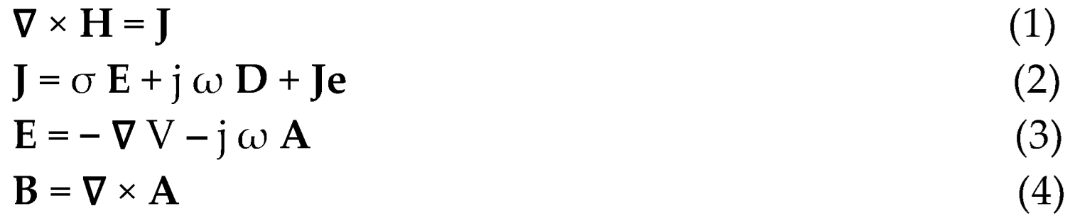
In (1-4), H and E are the magnetic and electric fields respectively in (A/m) and (V/m), B and D are the magnetic and electric inductions respectively in (T) and (C/ m2), A and V are the magnetic vector and electric scalar potentials respectively in (W/m) and (V). J and Je are the total and source current densities in (A/m2), σ is the electric conductivity in (S/m) and ω is the radial frequency pulsation = 2π f, f in (Hz). The symbol ∇ is a vector of partial derivative operators, and its three possible implications are gradient (product with a scalar field), divergence and curl (dot and cross products respectively with a vector field). The magnetic and electric comportment laws respectively between B/H and D/E are represented by the permeability μ and the permittivity ε respectively in (H/m) and (F/m).
The solution of equations (1-4) allows to determine in a system the EMFs for a given frequency pulsation taking into account the behaviors of magnetic materials via permeability, the eddy currents in electrical conductors across electrical conductivity and the displacement currents in dielectrics thru permittivity. Such solution can be achieved through local numerical discretized approaches or other methods allowing local calculations see e.g. [116-122].
EMF Equations Solution and EMC
EMC analysis can monitor via such a solution EMF disturbances due to the insertion of external objects into the birdcage RF coil of an MRI (section 3). In addition, this can control disturbances by an external EMF source in a target device, indicating its degree of EMF sensitivity (section 4). In these situations, it is necessary to check MRI compatibility (integrity of the RF field in the presence of inserted objects) and the insensitivity of onboard devices to EMF. This can be achieved by comparing the field distributions without and with disturbing elements. The field constancy in the case of exposed shielded onboard devices will be checked inside the device without and with exposure.
Indeed, for a given field source value Ee corresponding to Je, the solution of (1-4) in the discretized elements will give the induced values of the EMFs, E, B, J in each element. The obtained distribution of these EMFs allows EMC control. The source Ee corresponds to RF source B1 in the case of MRI or to the exposure of external EMF in the case of onboard devices. The solution domains will be respectively the birdcage in the tunnel of the MRI or the onboard device structure. The checked EMC control will be practiced on the induced EMFs distributions in each of these solution domains. This will consist of the verification of the integrity (constancy) of the field distributions in the solution domains regarding object insertion in the MRI case or EMF exposure in onboard device case. Such EMC controls could be done on the checked instrument isolated to guarantee its proper functioning. However, these devices (MRI or onboard devices) work normally close to body tissues and can interact together. Such interaction can affect the device behavior as well as the tissues and in certain situations, we may need to consider the body tissue in the solution domain.
5.2. Body Numerical Virtual Models
As discussed in the last sections, two categories of healthcare medical devices are affected by EMF-related disturbances and EMC control to monitor these disturbances. Such EMC monitoring can be carried out for isolated disturbed elements in the absence of living human tissues undergoing treatment. However, such control can take into account real environmental conditions and in particular the effects of the patient's bodily presence. This could be achieved experimentally while avoiding any risk to the patient by using a physical copy of the body (phantom) constructed from materials reflecting the body's true biological possessions. The same consideration of real conditions can be practiced in EMC analysis by mathematical modeling via digital control taking into account virtual copies of physical bodies (virtual phantom). Note that such virtual representations also make it possible to identify side effects on health due to medical devices disrupted by EMFs.
Much research has been carried out on building models of human bodies. In general, these models require detailed data on the dielectric properties of living tissues for different parts of the body. These can be obtained from permittivity and electrical conductivity measurement data as a function of frequency. Thus, it is possible to construct an accurate and high-resolution tissue model [123-127]. Such a model corresponds well to local discretized numerical methods used for the calculation of induced fields in medical devices and human tissues.
5.3. Qualitative Methodology Case Study Example
Considering a simple case to demonstrate the conferred control strategy of compatibility of matters introduced into the birdcage RF coil located inside an MRI tunnel. The concerned geometry consists of a birdcage of 30 cm diameter, 30 cm length, positioned in a 60 cm diameter tunnel. The checked materials are of a cubic form of 5 cm edge inserted in the birdcage coil center. Taking a RF field in the birdcage coil of 63.87 MHz consistent to the frequency fL (for B0 = 1.5 T), which is tuned to the central value of the geometry. The RF field distribution is computed in the tunnel based on 3D discretization of the E field on edge finite elements associated to appropriate boundary conditions. Computations have been done for the reference case without material and for different matters. Figure 4, illustrates a comparison of the reference case (a), aluminum conductor (b) and PZT piezoelectric (c). The characteristics of the piezoelectric are µr = 1.0, εr = [450 990 990], σ = 0 S/m. Note that the relative permittivity is given by an anisotropic vector where the value in polarization direction is smaller compared to the other directions. The characteristics of the conductor are µr = 1.0, εr = 1.0, σ = 3.77 × 10⁷ S/m.
As expected, as shown in figure 4, dielectric piezoelectric matter shows no effect while conducting material alter the distribution of the field. We have chosen to illustrate the conductor case due to fact that the perturbation is related to the orientation of the introduced matter and its surface perpendicular to the RF B1 field axis (see section 3.1). Note that the currents induced by a field in a conductor are developed in the section of the conductor perpendicular to the direction of the field.
Notice that the field distributions of figures 4- a, b and c are obtained for identical input conditions; therefore, they suggest a behavioral evocation.
Now, the present EMC analysis in MRI illuminates a procedure for inspection of disturbances in image-guided exercises.
6. Discussion
In this contribution, the analysis and evaluation carried out with a view to monitoring disturbances due to EMF noise in medical devices working close to living tissues, have demonstrated that such a subject is fully significant. At this stage, several issues are worth discussing:
- Implanted treatments have been considered in the last sections in two different situations. The case of implanted treatment that need movement or location control with augmented accuracy, which has been considered in section 3 regarding image-assisted treatments. The other concerned static passive and active implanted devices considered in section 4 regarding onboard autonomous devices. The difference between these two cases relative to EMF noise perturbation is that in first, the treatment-implanted procedure could perturb the function of the assisting MRI, while in the second; an external exposure source could disturb the function of the implanted onboard device.
- As discussed in Section 5.2., regarding EMC control using mathematical modeling analysis, the incorporation of virtual phantoms representing the patient's tissues involved in the medical treatment using the disturbed device might be necessary. This allows taking into account more realistic operating conditions for medical devices under control. Such a check is provided separately to guarantee the proper functioning of the device. However, in certain cases, this functioning could be linked to neighboring tissues and in particular under exposure to EMF. In fact, EMF exposure can produce biological thermal effects in living tissues that may be greater with longer durations. Under such conditions, consideration of virtual phantoms in the control model permits the consideration of unshielded device malfunction effect associated with biological thermal effect due to EMF exposure. It should be noted that such a malfunction could lead to tissue heating caused by heated metal parts involved in the device. Additionally, in the case of shielded onboard devices, the shielding materials are often electrically conductive. Even if the device in this case is protected of exposure to EMFs, the induced currents can heat the metal of the shield, which can cause tissue heating. This thermal behavior mainly concerns onboard devices, which may be subject to long EMF exposure intervals. In the case of image-assisted treatments, it may be noted that the MRI RF field exposure to the body tissues occurs for short intervals.
- In the case of onboard devices exposed to EMF waves, we consider four options for exposure. The first concerns devices made of materials insensitive to EMF (no magnetic or conductive material); in this case, exposure to electromagnetic fields will not disrupt the device but can only affect living tissue. The second case concerns devices comprising materials sensitive to EMF (magnetic and/or conductive material). In such a case, the device will be disturbed by EMF exposure and the tissues will be affected directly by the exposure and indirectly by the disturbed device. The third case concerns the last device but shielded with a simple conductive material. In this case, the exposure will not disrupt the operation of the device, but the tissues will be affected directly by the exposure and indirectly by the shield. The fourth option concerns the adaptation of the conductive nature of the shielding. Indeed, electromagnetic radiation shielding is corroborated to two basic loss types, reflection and absorption losses. In the occurrence of a conductive shield, the surface electric impedance can be written function of electromagnetic parameters, as Zs = (ω. μ /σ) 1/2. This impedance is much lower than the free space impedance Z0 = (μ0 / ε0) 1/2 ≈ 376.7 ohm. If a plane field wave hits the shield, a high impedance discrepancy triggers strong reflections. The surviving field is conveyed across the shield after part absorption. The radiated field with elevated frequencies as RF only infiltrates the close surface section of a conductor, due to skin effect. The depth of penetration δ (skin depth) can be expressed as δ = (ω. μ. σ /2) -1/2. Note that this expression is only utilizable if δ is superior to the mean free path of electron within the material. Regarding the losses due to reflection and absorption, the first diminishes with the frequency while the second that is correlated to the thickness of the shield, rises with the frequency. The total sum of these losses perform the total shielding (screening) effectiveness (SE), which is termed as the ratio of strengths of EMFs without and with the shielded device. Thus, in the last option regarding the adaptation of the conductive nature of the shielding, the use of multifunctional matched materials for low reflectivity EMI shielding can provide improved protection. The material tailoring can reduce the strong EM reflection caused by the high conductivity of the material. Additionally, a specific manufacturing process can reduce the reflected power coefficient of the material, added to reduced losses and improved thermal insulation and environmentally friendly shielding materials, see e.g. [128-130]. In conclusion, only a device made from EMF-insensitive materials or elegantly shielded, and exposed to EMF for a short interval, can be safe.
- In case of continuous or prolonged exposure to EMF waves of onboard devices working near human tissues, EMC monitoring of the device must be accompanied by an assessment of tissue heating. This can be accomplished by a coupled solution of the EMF-bio thermal heat transfer equations [33, 102, 131]. Indeed, the thermal behavior of tissues can be determined from the EMF power loss dissipated in, the tissues on one side and, in conductive metals of unshielded or in simple conductive shields of devices in the other side. These dissipated losses can be calculated from the induced EMFs obtained from the 3D solution of (1-4). The value of this EMF power loss can be used as the input heat source in the 3D solution of the heat transfer equation. Such a solution provides access to the ΔT distribution of the temperature rise in the solution domain concerned. The thermal behavior in living tissues is governed by the Penne’s bio-heat equation [33, 102, 131]. Note that the dissipated power density Pd = σ. E2 / 2 in conductors and Pd = ω ⋅ ε″ ⋅ E2 /2 in dielectrics (tissues) where E the absolute peak value of the electric field strength (V/m), ε″ is the imaginary part of the complex permittivity of the absorbing material and Pd is in (W/m3). The bio-heat equation is given by: c ρ ∂T /∂t = ∇ · (k ∇T) + Pd + qmet –𝑐𝑏 𝜌𝑏 𝜔b (T − Tb) , where, k is thermal conductivity, ρ is the material density, c is the specific heat of the substance, T local temperature in ºC, qmet is the basal metabolic heat source in W/m3 , cb is blood specific heat in J/ (kg. ºC), 𝜌𝑏 is blood density in kg/ m3, 𝜔b is blood perfusion rate (1/s), Tb blood temperature in ºC. ∇ · (k ∇T) symbolizes heat equation in differential form. Figure 5 illustrates the control strategies for onboard devices in case of exposure to EMF, involving exposure behaviors, device integrity and temperature rise in living body tissues.
- Following the example given in section 5.3, concerning the distribution of the RF field under the effect of the introduction of external materials, certain details deserve to be underlined. The first concerns the characteristics of matter affecting the modification of the field distribution. These involve, in addition to physical behavior, size, shape and orientation in space in relation to the direction of the field. The size is directly related to the importance of the disturbance of the field distribution. For very small sizes, generally the disturbances could be negligible or easily compensated. Magnetic materials are the most disruptive around its volume and should be avoided. Dielectric materials are practically non-disruptive. Disturbances linked to conductive materials are strongly linked to shape and spatial orientation. The larger the surface of the conductor perpendicular to the axis of B1, the greater the induced eddy currents and associated field disturbances will be. Thus, a conductive sheet of insignificant thickness positioned parallel to the field will hardly disturb the field distribution. This observation may facilitate the use of thin electrodes for properly positioned devices in the RF coil without field disturbance. Typical examples of non-disruptive field distribution could be piezoelectric sensors and actuators composed of piezoelectric stacks, which behave dielectrically, equipped with thin sheet electrodes, which can be controlled to be parallel to the field direction [54, 121, 132-140].
7. Conclusions
In this contribution, the evaluation, discussion and analysis of disturbances due to EMF noise of medical devices working near living tissues and the corresponding functional EMC control of these devices were carried out. Analysis of the different interests covered in this review revealed that there is persistent development in this area. The important elements raised by this theme are diverse, the most important of which are summarized as follows.
An important goal of healthcare management could be to ensure the proper functioning of medical instruments working close to the patient's body tissues and enable their protection by monitoring potential disturbances. Thanks to these commitments, different health recommendations can be advocated:
- Image-assisted robotics involving MRI and piezoelectric devices offer support for patient well-being.
- Conductive materials can be introduced into the MRI subject to particular shapes and spatial orientation in addition to EMC verification.
- Embedded devices constructed from EMF-insensitive materials or intelligently shielded can be used safely with short EMF exposure intervals.
- In case of continuous or prolonged EMF exposure, the increase in body tissue temperature must be supervised in addition to EMC monitoring.
- The use of virtual tissue models in EMC testing allows for more realistic evaluation capabilities.
Funding
This research received no external funding.
Conflicts of Interest
The authors declare no conflict of interest.
References
- Petroulakis, N; Mattsson, MO; Chatziadam, P et al. NextGEM: Next-Generation Integrated Sensing and Analytical System for Monitoring and Assessing Radiofrequency Electromagnetic Field Exposure and Health. Int. J. Env. Res. Public. Health. 2023, 20, 6085. [Google Scholar] [CrossRef] [PubMed]
- Henschenmacher, B; Bitsch, A; de Las Heras Gala, T et al. The effect of radiofrequency electromagnetic fields (RF-EMF) on biomarkers of oxidative stress in vivo and in vitro: A protocol for a systematic review. Env. Int. 2022, 158, 106932. [Google Scholar] [CrossRef] [PubMed]
- Hamed, T.; Maqsood, M. SAR Calculation & Temperature Response of Human Body Exposure to Electromagnetic Radiations at 28, 40 and 60 GHz mm Wave Frequencies. Prog. Electromagn. Res. M. 2018, 73, 47–59. [Google Scholar] [CrossRef]
- Lagorio, S.; Blettner, M.; Baaken, D.; Feychting, M.; Karipidis, K.; Loney, T. The effect of exposure to radiofrequency fields on cancer risk in the general and working population: A protocol for a systematic review of human observational studies. Environ. Int. 2021, 157, 106828. [Google Scholar] [CrossRef] [PubMed]
- Romeo, S.; Zeni, O.; Sannino, A.; Lagorio, S.; Biffoni, M.; Scarfì, M.R. Genotoxicity of radiofrequency electromagnetic fields: Protocol for a systematic review of in vitro studies. Environ. Int. 2021, 148, 106386. [Google Scholar] [CrossRef] [PubMed]
- Pophof, B.; Burns, J.; Danker-Hopfe, H et al. The effect of exposure to radiofrequency electromagnetic fields on cognitive performance in human experimental studies: A protocol for a systematic review. Env. Int. 2021, 157, 106783. [Google Scholar] [CrossRef] [PubMed]
- Kovács, A.; Bischoff, P.; Haddad, H.; Kovács, G.; Schaefer, A.; Zhou, W.; Pinkawa, M. Personalized Image-Guided Therapies for Local Malignencies: Interdisciplinary Options for Interventional Radiology and Interventional Radiotherapy. Front. Oncol. 2021, 11. [Google Scholar] [CrossRef]
- Zhao, J.; Zhi, Z.; Zhang, H.; Zhao, J.; Di, Y.; Xu, K.; Ma, C.; Liu, Z.; Sui, A.; Wang, J. Efficacy and safety of CT guided 125I brachytherapy in elderly patients with non small cell lung cancer. Oncol. Lett. 2020, 20, 183–192. [Google Scholar] [CrossRef]
- Park, B.K. Ultrasound-guided genitourinary interventions: principles and techniques (Review Article). Ultrasonography 2017, 36, 336–348. [Google Scholar] [CrossRef]
- Pinto, P.A.; Chung, P.H.; Rastinehad, A.R.; Baccala, A.A. Jr; Kruecker, J.; Benjamin, C.J.; et al. Magnetic resonance imaging/ultrasound fusion guided prostate biopsy improves cancer detection following transrectal ultrasound biopsy and correlates with multiparametric magnetic resonance imaging. J. Urol. 2011, 186, 1281–1285. [Google Scholar] [CrossRef]
- Fiard, G.; Hohn, N.; Descotes, JL.; Rambeaud, JJ.; Troccaz, J.; Long, JA. Targeted MRI-guided prostate biopsies for the detection of prostate cancer: initial clinical experience with real-time 3-dimensional transrectal ultrasound guidance and magnetic resonance/transrectal ultrasound image fusion. Urology 2013, 81, 1372–1378. [Google Scholar] [CrossRef]
- Veltri, A.; Garetto, I.; Pagano, E.; Tosetti, I.; Sacchetto, P.; Fava, C. Percutaneous RF thermal ablation of renal tumors: is US guidance really less favorable than other imaging guidance techniques? Cardiovasc. Interv. Radiol. 2009, 32, 76–85. [Google Scholar] [CrossRef]
- Bassignani, M.; Moore, Y.; Watson, L.; Theodorescu, D. Pilot experience with real-time ultrasound guided percutaneous renal mass cryoablation. J. Urol. 2004, 171, 1620–1623. [Google Scholar] [CrossRef]
- Guk, K.; Han, G.; Lim, J.; Jeong, K.; Kang, T.; Lim, E.-K.; Jung, J. Evolution of Wearable Devices with Real-Time Disease Monitoring for Personalized Healthcare. Nanomaterials 2019, 9, 813. [Google Scholar] [CrossRef]
- Xin, Y.; Liu, T.; Sun, H.; Xu, Y.; Zhu, J.; Qian, C.; Lin, T. Recent progress on the wearable devices based on piezoelectric sensors. Ferroelectrics 2018, 531, 102–113. [Google Scholar] [CrossRef]
- Yetisen, A.K.; Martinez-Hurtado, J.L.; Ünal, B.; Khademhosseini, A.; Butt, H. Wearables in Medicine. Adv. Mater. 2018, 30, 1706910. [Google Scholar] [CrossRef] [PubMed]
- Sener, T.; Haenen, W.; Smits, P.; Hans, GH. Large-scale real-life implementation of technology-enabled care to maximize hospitals' medical surge preparedness during future infectious disease outbreaks and winter seasons: a viewpoint. Front. Public. Health. 2023, 11, 1149247. [Google Scholar] [CrossRef] [PubMed]
- Navarro-Valverde, C.; Ramos-Maqueda, J.; Romero-Reyes, MJ et al. Magnetic resonance imaging in patients with cardiac implantable electronic devices: A prospective study. Magn. Reson. Imaging. 2022, 91, 9–15. [Google Scholar] [CrossRef] [PubMed]
- Hirano, M.; Muto, Y.; Kuroda, M. Quantitative evaluation of the reduction of distortion and metallic artifacts in magnetic resonance images using the multiacquisition variable resonance image combination selective sequence. Experimental and Therapeutic Medicine 2023, 25109. [Google Scholar] [CrossRef] [PubMed]
- Amann, N.; Johnson, S.; Chagarlamudi, K.; Gupta, A.; Faraji, N. Scheduling Musculoskeletal MRI for Patients With Metallic Hardware: Initial Observations on Decreasing Nondiagnostic and Repeat Examinations at a Multisite Academic Medical Center. Curr. Probl. Diagn. Radiol. 2023, 52, 327–329. [Google Scholar] [CrossRef] [PubMed]
- Fujiwara, Y.; Sasaki, T.; Muto, Y, et al. Multiacquisition Variable-Resonance Image Combination Selective Can Improve Image Quality and Reproducibility for Metallic Implants in the Lumbar Spine. Acta Medica Okayama. 2021, 75, 187–197. [Google Scholar] [CrossRef] [PubMed]
- Choo, HJ.; Lee, SJ.; Lee, YH. Metallic Artifacts on MR Imaging and Methods for Their Reduction. Taehan Yongsang Uihakhoe Chi. 2020, 81, 41–57. [Google Scholar] [CrossRef] [PubMed]
- Chinzei, K.; Kikinis, R.; Jolesz, FA. MR compatibility of mechatronic devices: design criteria. MICCAI (1679) 1999, 1020–1030. [Google Scholar]
- Tsekos, NV.; Khanicheh, A.; Christoforou, E.; Mavroidis, C. Magnetic resonance-compatible robotic and mechatronics systems for image guided interventions and rehabilitation: A Review Study. Annu. Rev. Biomed. Eng. 2007, 9, 351–387. [Google Scholar] [CrossRef] [PubMed]
- Khairi, R.; Razek, A.; Bernard, L.; Corcolle, R.; Bernard, Y.; Pichon, L.; Poirier-Quinot, M.; Ginefri, JC. EMC analysis of MRI environment in view of Optimized performance and cost of image guided interventions. Int. Jour. App. Electromag. Mech. 2016, 51, S67–S74. [Google Scholar] [CrossRef]
- Su, H.; Kwok, KW.; Cleary, K.; Iordachita, I.; Cavusoglu, MC. ; Desai, JP ; Fischer, GS. State of the art and future opportunities in MRI-guided robot-assisted surgery and interventions. Proceedings of the IEEE, .7. [CrossRef]
- Razek, A. Towards an image-guided restricted drug release in friendly implanted therapeutics. Eur. Phys. J. Appl. Phys. 2018, 82, 31401. [Google Scholar] [CrossRef]
- Velazco Garcia, JD.; Navkar, NV.; Gui, D et al. A Platform Integrating Acquisition, Reconstruction, Visualization, and Manipulator Control Modules for MRI-Guided Interventions. J. Digit. Imaging. 2019, 32, 420–432. [Google Scholar] [CrossRef]
- Razek, A. Assessment of Supervised Drug Release in Cordial Embedded Therapeutics. Athens J. Technol. Eng. 2019, 6, 77–91. [Google Scholar] [CrossRef]
- Chakrabarti S, Biswas N, Jones LD, Kesari, S. , Ashili, S. Smart Consumer Wearables as Digital Diagnostic Tools: A Review. Diagnostics 2022, 12, 2110. [Google Scholar] [CrossRef]
- Escobar-Linero, E.; Muñoz-Saavedra, L.; Luna-Perejón, F.; Sevillano, J.L.; Domínguez-Morales, M. Wearable Health Devices for Diagnosis Support: Evolution and Future Tendencies. Sensors 2023, 23, 1678. [Google Scholar] [CrossRef] [PubMed]
- Devi DH, Duraisamy K, Armghan A, et al. 5G Technology in Healthcare and Wearable Devices: A Review. Sensors 2023, 23, 2519. [Google Scholar] [CrossRef]
- Razek, A. Biological and Medical Disturbances Due to Exposure to Fields Emitted by Electromagnetic Energy Devices—A Review. Energies 2022, 15, 4455. [Google Scholar] [CrossRef]
- Sato, Y.; Takeuchi, T.; Fuju, A. MRI safety for leave-on powdered hair thickeners under 1.5-T and 3.0-T MRI: measurement of deflection force, MRI artifact, and evaluation of preexamination screening. Phys. Eng. Sci. Med. 2023, 46, 915–924. [Google Scholar] [CrossRef]
- Akdogan, G.; Istanbullu, O. Analysing the effects of metallic biomaterial design and imaging sequences on MRI interpretation challenges due to image artefacts. Phys. Eng. Sci. Med. 2022, 45, 1163–1174. [Google Scholar] [CrossRef]
- Germann, C.; Nanz, D.; Sutter, R. Magnetic Resonance Imaging Around Metal at 1.5 Tesla: Techniques From Basic to Advanced and Clinical Impact. Invest. Radiol. 2021, 56, 734–748. [Google Scholar] [CrossRef] [PubMed]
- Germann, C.; Falkowski, A.L.; von Deuster, C.; Nanz, D.; Sutter, R. Basic and Advanced Metal-Artifact Reduction Techniques at Ultra-High Field 7-T Magnetic Resonance Imaging-Phantom Study Investigating Feasibility and Efficacy. Invest. Radiol. 2022, 57, 387–398. [Google Scholar] [CrossRef]
- Inaoka, T.; Kitamura, N.; Sugeta, M. Diagnostic Value of Advanced Metal Artifact Reduction Magnetic Resonance Imaging for Periprosthetic Joint Infection. J. Comput. Assist. Tomogr. 2022, 46, 455–463. [Google Scholar] [CrossRef]
- Haskell, M.W.; Nielsen, J.F.; Noll, D.C. Off-resonance artifact correction for MRI: A review. NMR Biomed. 2023, 36, e4867. [Google Scholar] [CrossRef] [PubMed]
- Spronk, T.; Kraff, O.; Kreutner, J.; Schaefers, G.; Quick, HH. Development and evaluation of a numerical simulation approach to predict metal artifacts from passive implants in MRI. Magma 2022, 35, 485–497. [Google Scholar] [CrossRef]
- Farooq, MU.; Ko, SY. A Decade of MRI Compatible Robots: Systematic Review. Trans. Rob. 2023, 39, 862–884. [Google Scholar] [CrossRef]
- Farooq, MU. An MRI-compatible endonasal surgical robotic system: Kinematic analysis and performance evaluation. Mechatronics 2023, 94, 103029. [Google Scholar] [CrossRef]
- Manjila, S.; Rosa, B.; Price, K.; Manjila, R.; Mencattelli, M.; Dupont, PE. Robotic Instruments Inside the MRI Bore: Key Concepts and Evolving Paradigms in Imaging-enhanced Cranial Neurosurgery. World Neurosurg. 2023, 176, 127–139. [Google Scholar] [CrossRef]
- Zhao, Z. et al. Preliminary Characterization of a Plastic Piezoelectric Motor Stator Using High-Speed Digital Holographic Interferometry. In: Lin, MT., Furlong, C., Hwang, CH. (eds) Adv of Optl Methods & Digital Image Correlation in Experimental Mechanics. Conf. Proc. of the Soc. for Exper. Mech. Series. Springer, Cham. 2021. [CrossRef]
- Carvalho, P.A. et al. Study of MRI Compatible Piezoelectric Motors by Finite Element Modeling and High-Speed Digital Holography. In: Lin, MT., et al. Adv. in Opt. Meth. & Dig. Image Correl. in Exper. Mech., 3. Conference Proceedings of the Society for Experimental Mechanics Series. Springer, Cham. 2020. [CrossRef]
- Zhang, SJ.; Liu, Y.; Deng, J.; Gao, X.; Li, J.; Wang, WY.; Xun, MX.; Ma, XF.; Chang, QB.; Liu, JK.; Chen, WS.; Zhao, J. Piezo robotic hand for motion manipulation from micro to macro. Nat. Commun. 2023, 14, 500. [Google Scholar] [CrossRef]
- Mohith, S.; Upadhya, A.R.; Navin, K.P.; Kulkarni, S.M.; Rao, M. Recent trends in piezoelectric actuators for precision motion and their applications: A review. Smart Mater. Struct. 2020, 30, 013002. [Google Scholar] [CrossRef]
- Gao, X.; Yang, J.; Wu, J.; Xin, X.; Li, Z.; Yuan, X.; Shen, X.; Dong, S. Piezoelectric Actuators and Motors: Materials, Designs, and Applications. Adv. Mater. Technol. 2020, 5, 1900716. [Google Scholar] [CrossRef]
- Qiao, G.; Li, H.; Lu, X.; Wen, J.; Cheng, T. Piezoelectric stick-slip actuators with flexure hinge mechanisms: A review. J. Intell. Mater. Syst. Structures. 2022, 33, 1879–1901. [Google Scholar] [CrossRef]
- Liu, J.; Gao, X.; Jin, H. Miniaturized electromechanical devices with multi-vibration modes achieved by orderly stacked structure with piezoelectric strain units. Nat. Commun. 2022, 13, 6567. [Google Scholar] [CrossRef] [PubMed]
- Fu, D.K.; Fan, P.Q.; Yuan, T.; Wang, Y.S. A novel hybrid mode linear ultrasonic motor with double driving feet. Rev. Sci. Instrum. 2022, 93, 025003. [Google Scholar] [CrossRef] [PubMed]
- Li, Z.; Guo, Z.; Han, H.; Su, Z.; Sun, H. Design and characteristic analysis of multi-degree-of-freedom ultrasonic motor based on spherical stator. Rev. Sci. Instrum. 2022, 93, 025004. [Google Scholar] [CrossRef] [PubMed]
- Wang, S.; Zhou, S.; Zhang, X. Bionic Stepping Motors Driven by Piezoelectric Materials. J. Bionic Eng. 2023, 20, 858–872. [Google Scholar] [CrossRef]
- Hernandez, C.; Bernard, Y.; Razek, A. Design and manufacturing of a piezoelectric traveling-wave pumping device. IEEE Trans. on Ultrasonics, Ferroelectrics, and Frequency Control 2013, 60, 1949–1956. [Google Scholar] [CrossRef] [PubMed]
- Yang, Z.; Li, X.; Tang, J. A Bionic Stick–Slip Piezo-Driven Positioning Platform Designed by Imitating the Structure and Movement of the Crab. J. Bionic Eng. 2023. [Google Scholar] [CrossRef]
- Virtanen, J Enhancing the compatibility of surgical robots with magnetic resonance imaging, PhD thesis, University of Oulu, Oulu, Finland, 2006. http://urn. 9514.
- Tada, M.; Sasaki, S.; Ogasawara, T. Development of an optical 2-axis force sensor usable in MRI environments. SENSORS, 2002 IEEE, Orlando, FL, USA, 2002, 2, 984–989. [Google Scholar] [CrossRef]
- Tada, M.; Kanade, T. An MR-Compatible Optical Force Sensor for Human Function Modeling. In: Barillot, C., Haynor, D.R., Hellier, P. (eds) Medical Image Computing and Computer-Assisted Intervention – MICCAI 2004. Lecture Notes in Computer Science, 3217. Springer, Berlin, Heidelberg. [CrossRef]
- Jolesz, FA; Morrison, PR; Koran, SJ et al. Compatible instrumentation for intraoperative MRI: expanding resources. J. Magn. Reson. Imaging. 1998, 8, 8–11. [Google Scholar] [CrossRef] [PubMed]
- Shellock, F.G. : Pocket Guide to MR Procedures and Metallic Objects: Update 1998. Lippincott-Raven publishers, Philadelphia 1998. https://archive. 0000. [Google Scholar]
- Schenck, JF. The role of magnetic susceptibility in magnetic resonance imaging: MRI magnetic compatibility of the first and second kinds. Med. Phys. 1996, 23, 815–850. [Google Scholar] [CrossRef] [PubMed]
- Traverson, M; Heiden, M; Stanciu, LA; Nauman, EA; Jones-Hall, Y. ; Breur, GJ. In Vivo Evaluation of Biodegradability and Biocompatibility of Fe30Mn Alloy. Vet. Comp. Orthop. Traumatol. 2018, 31, 10–16. [Google Scholar] [CrossRef] [PubMed]
- Wang, Y.; Venezuela, J.; Dargusch, M. Biodegradable shape memory alloys: Progress and prospects. Biomaterials. 2021, 279, 121215. [Google Scholar] [CrossRef]
- Li, H.; Lin, G.; Wang, P.; Huang, J.; Wen, C. Nutrient alloying elements in biodegradable metals: a review. J. Mater. Chem. B. 2021, 9, 9806–9825. [Google Scholar] [CrossRef]
- Rabeeh, VPM. ; Hanas, T. Progress in manufacturing and processing of degradable Fe-based implants: a review. Prog. Biomater. 2022, 11, 163–191. [Google Scholar] [CrossRef]
- Babacan, N.; Kochta, F.; Hoffmann, V.; Gemming, T. et al. Effect of silver additions on the microstructure, mechanical properties and corrosion behavior of biodegradable Fe-30Mn-6Si, Materials Today Communications 2021, 28, 102689, 2352-4928. [CrossRef]
- Tai, C.-C.; Lo, H.-L.; Liaw, C.-K.; Huang, Y.-M.; Huang, Y.-H.; Yang, K.-Y.; Huang, C.-C.; Huang, S.-I.; Shen, H.-H.; Lin, T.-H.; et al. Biocompatibility and Biological Performance Evaluation of Additive-Manufactured Bioabsorbable Iron-Based Porous Suture Anchor in a Rabbit Model. Int. J. Mol. Sci. 2021, 22, 7368. [Google Scholar] [CrossRef]
- Bakhsheshi-Rad, H.R.; Najafinezhad, A.; Hadisi, Z.; Iqbal, N. Characterization and biological properties of nanostructured clinoenstatite scaffolds for bone tissue engineering applications. Mater. Chem. Phys. 2021, 259, 123969. [Google Scholar] [CrossRef]
- Sun, Y.; Chen, L.; Liu, N.; Wang, H.; Liang, C. Laser-modified fe–30mn surfaces with promoted biodegradability and biocompatibility toward biological applications. J. Mater. Sci. 2021, 56, 13772–13784. [Google Scholar] [CrossRef]
- Saliba, L.; Sammut, K.; Tonna, C.; Pavli, F. FeMn and FeMnag Biodegradable Alloys: An In Vitro And In Vivo Investigation. Available at SSRN: https://ssrn.com/abstract=4325636 or. [CrossRef]
- Hao, S.; Yang, T.; Zhang, A.; Wang, P.; Jiang, H.; Shen, D.; Guo, L.; Ye, M. Evaluation of Biodegradable Alloy Fe30Mn0.6N in Rabbit Femur and Cartilage through Detecting Osteogenesis and Autophagy. Biomed. Res. Int. 2023, 18, 2023:3626776. [Google Scholar] [CrossRef]
- Biffi, C.A.; Fiocchi, J.; Bregoli, C.; Gambaro, S.; Copes, F.; Mantovani, D.; Tuissi, A. Ultrashort Laser Texturing for Tuning Surface Morphology and Degradation Behavior of the Biodegradable Fe–20Mn Alloy for Temporary Implants. Adv. Eng. Mater. 2022, 24, 2101496. [Google Scholar] [CrossRef]
- Putra, N.E.; Leeflang, M.A.; Taheri, P.; Fratila-Apachitei, L.E.; Mol, J.M.C.; Zhou, J.; Zadpoor, A.A. Extrusion-based 3D printing of ex situ-alloyed highly biodegradable MRI-friendly porous iron-manganese scaffolds, Acta Biomaterialia 2021, 134, 774–790. [CrossRef]
- Soliman, M.M.; Chowdhury, M.E.H.; Khandakar, A.; Islam, M.T.; Qiblawey, Y.; Musharavati, F.; Zal Nezhad, E. Review on Medical Implantable Antenna Technology and Imminent Research Challenges. Sensors 2021, 21, 3163. [Google Scholar] [CrossRef] [PubMed]
- Gupta, A.; Kumar, V.; Bansal, S.; Alsharif, M.H.; Jahid, A.; Cho, H.-S. A Miniaturized Tri-Band Implantable Antenna for ISM/WMTS/Lower UWB/Wi-Fi Frequencies. Sensors 2023, 23, 6989. [Google Scholar] [CrossRef] [PubMed]
- Chowdhury, M.E.H.; Khandakar, A.; Alzoubi, K.; Mansoor, S.; M. Tahir, A.; Reaz, M.B.I.; Al-Emadi, N. Real-Time Smart-Digital Stethoscope System for Heart Diseases Monitoring. Sensors 2019, 19, 2781. [Google Scholar] [CrossRef] [PubMed]
- Moon KS, Lee SQ. A Wearable Multimodal Wireless Sensing System for Respiratory Monitoring and Analysis. Sensors 2023, 23, 6790. [Google Scholar] [CrossRef] [PubMed]
- Khan Mamun, MMR. ; Sherif, A. Advancement in the Cuffless and Noninvasive Measurement of Blood Pressure: A Review of the Literature and Open Challenges. Bioengineering 2022, 10, 27. [Google Scholar] [CrossRef]
- Bhuva, AN; Moralee, R. ; Brunker, T et al. Evidence to support magnetic resonance conditional labelling of all pacemaker and defibrillator leads in patients with cardiac implantable electronic devices. Eur. Heart J. 2022, 43, 2469–2478. [Google Scholar] [CrossRef] [PubMed]
- Joo, H.; Lee, Y.; Kim, J.; Yoo, J.S.; Yoo, S.; Kim, S.; Arya, A.K.; Kim, S.; Choi, S.H.; Lu, N. Soft Implantable Drug Delivery Device Integrated Wirelessly with Wearable Devices to Treat Fatal Seizures. Sci. Adv. 2021, 7, eabd4639. [Google Scholar] [CrossRef]
- Cheng, Y.; Xie, D.; Han, Y et al. Precise management system for chronic intractable pain patients implanted with spinal cord stimulation based on a remote programming platform: study protocol for a randomized controlled trial (PreMaSy study). Trials. 2023, 24, 580. [Google Scholar] [CrossRef]
- Thotahewa, K.M.S.; Redouté, J.; Yuce, M.R. Electromagnetic and thermal effects of IR-UWB wireless implant systems on the human head. 2013 35th Annual International Conference of the IEEE Engineering in Medicine and Biology Society (EMBC) 2013, 5179–5182. [Google Scholar] [CrossRef]
- Corbett, GD.; Buttery, PC.; Pugh, PJ.; Cameron EAB. Endoscopy and implantable electronic devices. Frontline Gastroenterol. 2012, 3, 72–75. [Google Scholar] [CrossRef]
- Pantelopoulos, A.; Bourbakis, N.G. A survey on wearable sensor-based systems for health monitoring and prognosis. IEEE Trans. Syst. Manand Cybern. Part. C 2010, 40, 1–12. [Google Scholar] [CrossRef]
- Chan, M.; Esteve, D.; Fourniols, J.Y.; Escriba, C.; Campo, E. Smart wearable systems: Current status and future challenges. Artif. Intell. Med. 2012, 56, 137–156. [Google Scholar] [CrossRef]
- Kim, J.; Campbell, A.S.; de Ávila, B.E.; Wang, J. Wearable biosensors for healthcare monitoring. Nat. Biotechnol. 2019, 37, 389–406. [Google Scholar] [CrossRef]
- Khan, Y.; Ostfeld, A.E.; Lochner, C.M.; Pierre, A.; Arias, A.C. Monitoring of vital signs with flexible and wearable medical devices. Adv. Mater. 2016, 28, 4373–4395. [Google Scholar] [CrossRef] [PubMed]
- Patel, S.; Park, H.; Bonato, P.; Chan, L.; Rodgers, M. A review of wearable sensors and systems with application in rehabilitation. J. Neuroeng. Rehabil. 2012, 9, 1–17. [Google Scholar] [CrossRef] [PubMed]
- Hurley, NC.; Spatz, ES.; Krumholz, HM.; Jafari, R.; Mortazavi, BJ. A Survey of Challenges and Opportunities in Sensing and Analytics for Risk Factors of Cardiovascular Disorders. ACM Trans. Comput. Healthc. 2021, 2, 9–21. [Google Scholar] [CrossRef] [PubMed]
- Talal, M.; Zaidan, AA.; Zaidan, BB. Smart Home-based IoT for Real-time and Secure Remote Health Monitoring of Triage and Priority System using Body Sensors: Multi-driven Systematic Review. J. Med. Syst. 2019, 43, 42. [Google Scholar] [CrossRef]
- Patel, V.; Orchanian-Cheff, A.; Wu, R. Evaluating the Validity and Utility of Wearable Technology for Continuously Monitoring Patients in a Hospital Setting: Systematic Review. JMIR Mhealth Uhealth. 2021, 9, e17411. [Google Scholar] [CrossRef]
- Osama, M.; Ateya, A.A.; Sayed, M.S.; Hammad, M.; Pławiak, P.; Abd El-Latif, A.A.; Elsayed, R.A. Internet of Medical Things and Healthcare 4.0: Trends, Requirements, Challenges, and Research Directions. Sensors 2023, 23, 7435. [Google Scholar] [CrossRef] [PubMed]
- Electromagnetic Compatibility (EMC)—Part 6–1; IEC 61000-6-1:2019; IEC: Geneva, Switzerland, 2019.
- Electromagnetic Compatibility (EMC)—Methodology for the Achievement of the Functional Safety of Electrical and Electronic with Regard to Electromagnetic Phenomena; IEC/TS 61000-1-2; IEC: Geneva, Switzerland, 2019.
- CISPR 16-1-1 Specification for Radio Disturbance and Immunity Measuring Apparatus and Methods—Part 1-1: Radio Disturbance and Immunity Measuring Apparatus—Measuring Apparatus. 2019. Available online: https://webstore.iec.ch/publication/60774 (accessed on 5 October 2021).
- Sabath, F. A systematic approach for electromagnetic interference risk management. IEEE Electromagn. Compat. Mag. 2017, 6, 99–106. [Google Scholar] [CrossRef]
- Jang, J.; Paonni, M.; Eissfeller, B. CW Interference Effects on Tracking Performance of GNSS Receivers. IEEE Trans. Aerosp. Electron. Syst. 2012, 48, 243–258. [Google Scholar] [CrossRef]
- [Su, D.; Xie, S.; Chen, A.; Shang, X.; Zhu, K.; Xu, H. Basic emission waveform theory: A novel interpretation and source identification method for electromagnetic emission of complex systems. IEEE Trans. Electromagn. Compat. 2018, 60, 1330–1339. [Google Scholar] [CrossRef]
- Hoijer, M. Including Directivity in Reverberation Chamber Radiated Susceptibility Testing. IEEE Trans. Electromagn. Compat. 2011, 53, 283–287. [Google Scholar] [CrossRef]
- Spadacini, G.; Grassi, F.; Pignari, S.A.; Bisognin, P.; Piche, A. Bulk Current Injection as an Alternative Radiated Susceptibility Test Enforcing a Statistically Quantified Overtesting Margin. IEEE Trans. Electromagn. Compat. 2018, 60, 1270–1278. [Google Scholar] [CrossRef]
- Cai, S.; Li, Y.; Zhu, H.; Wu, X.; Su, D. A Novel Electromagnetic Compatibility Evaluation Method for Receivers Working under Pulsed Signal Interference Environment. Appl. Sci. 2021, 11, 9454. [Google Scholar] [CrossRef]
- Razek, A. Assessment of EMF Troubles of Biological and Instrumental Medical Questions and Analysis of Their Compliance with Standards. Standards 2023, 3, 227–239. [Google Scholar] [CrossRef]
- Chen, C.H.; Huang, C.Y.; Huang, Y.C. Improving the electromagnetic compatibility of electronic products by using response surface methodology and artificial neural network. Microelectron. Int. 2022, 39, 1–13. [Google Scholar] [CrossRef]
- Yang, Y.; Zeng, S.; Li, X.; Hu, Z.; Zheng, J. Ultrahigh and Tunable Electromagnetic Interference Shielding Performance of PVDF Composite Induced by Nano-Micro Cellular Structure. Polymers 2022, 14, 234. [Google Scholar] [CrossRef]
- Wang, G.; Wang, L.; Mark, L.H.; Shaayegan, V.; Wang, G.; Li, H.; Zhao, G.; Park, C.B. Ultralow-Threshold and Lightweight Biodegradable Porous PLA/MWCNT with Segregated Conductive Networks for High-Performance Thermal Insulation and Electromagnetic Interference Shielding Applications. ACS Appl. Mater. Interfaces 2018, 10, 1195–1203. [Google Scholar] [CrossRef] [PubMed]
- Yao, B.; Hong, W.; Chen, T.; Han, Z.; Xu, X.; Hu, R.; Hao, J.; Li, C.; Li, H.; Perini, S.E.; et al. Highly Stretchable Polymer Composite with Strain-Enhanced Electromagnetic Interference Shielding Effectiveness. Adv. Mater. 2020, 32, e1907499. [Google Scholar] [CrossRef] [PubMed]
- Yun, T.; Kim, H.; Iqbal, A.; Cho, Y.S.; Lee, G.S.; Kim, M.; Kim, S.J.; Kim, D.; Gogotsi, Y.; Kim, S.O.; et al. Electromagnetic Shielding of Monolayer MXene Assemblies. Adv. Mater. 2020, 32, e1906769. [Google Scholar] [CrossRef] [PubMed]
- Song, W.L.; Cao, M.S.; Lu, M.M.; Bi, S.; Wang, C.Y.; et al. , Flexible graphene/polymer composite films in sandwich structures for effective electromagnetic interference shielding. Carbon. 2014, 66, 67–76. [Google Scholar] [CrossRef]
- Song, W.L.; Guan, X.T.; Fan, L.Z.; Cao, W.Q.; Wang, C.Y.; et al. , Tuning three-dimensional textures with graphene aerogels for ultra-light flexible graphene/texture composites of effective electromagnetic shielding. Carbon. 2015, 93, 151–160. [Google Scholar] [CrossRef]
- Tan, Y.J.; Li, J.; Gao, Y.; Li, J.; Guo, S.; et al. A facile approach to fabricating silver-coated cotton fiber non-woven fabrics for ultrahigh electromagnetic interference shielding. Appl. Surf. Sci. 2018, 458, 236–244. [Google Scholar] [CrossRef]
- Han, M.; Yin, X.; Hantanasirisakul, K.; Li, X.; Iqbal, A.; et al. Anisotropic MXene aerogels with a mechanically tunable ratio of electromagnetic wave reflection to absorption. Adv. Opt. Mater. 2019, 7, 1900267. [Google Scholar] [CrossRef]
- Cheng, J.; Li, C.; Xiong, Y. Recent Advances in Design Strategies and Multifunctionality of Flexible Electromagnetic Interference Shielding Materials. Nano-Micro Lett. 2022, 14, 80. [Google Scholar] [CrossRef]
- Mohammad, M.; Wodajo, E.T.; Choi, S.; Elbuluk, M.E. Modeling and Design of Passive Shield to Limit EMF Emission and to Minimize Shield Loss in Unipolar Wireless Charging System for EV. IEEE Transactions on Power Electronics 2019, 34, 12235–12245. [Google Scholar] [CrossRef]
- Canova, A.; Corti, F.; Laudani, A.; Lozito, G.M.; Quercio, M. Innovative shielding technique for wireless power transfer systems. IET Power Electron. 2023, 00, 1–8. [Google Scholar] [CrossRef]
- Maxwell, JC. VIII. A dynamical theory of the electromagnetic field. Phil. Trans. R. Soc. 1865, 155, 459–512. [Google Scholar] [CrossRef]
- Nunes, A.S.; Dular, P.; Chadebec, O.; Kuo-Peng, P. Subproblems Applied to a 3-D Magnetostatic Facet FEM Formulation. IEEE Trans. Magn. 2018, 54, 7402209. [Google Scholar] [CrossRef]
- Batra, T.; Schaltz, E.; Ahn, S. Effect of ferrite addition above the base ferrite on the coupling factor of wireless power transfer for vehicle applications. J. Appl. Phys. 2015, 117, 17D517. [Google Scholar] [CrossRef]
- Piriou, F.; Razek, A. Numerical simulation of a nonconventional alternator connected to a rectifier. IEEE Trans. Energy Convers. 1990, 5, 512–518. [Google Scholar] [CrossRef]
- Padilha, J.B.; Kuo-Peng, P.; Sadowski, N.; Batistela, N.J. Vector Hysteresis Model Associated to FEM in a Hysteresis Motor 691 Modeling. IEEE Trans. Magn. 2017, 53, 7402004. [Google Scholar] [CrossRef]
- Ren, Z.; Razek, A. A coupled electromagnetic-mechanical model for thin conductive plate deflection analysis. IEEE Trans. Magn. 1990, 26, 1650–1652. [Google Scholar] [CrossRef]
- Hariri, H.; Bernard, Y. ; Razek, 2-D Traveling Wave Driven Piezoelectric Plate Robot for Planar Motion, IEEE/ASME Transactions on Mechatronics, vol. 23, no. 1, pp. 242–251, Feb. 2018. [CrossRef]
- Li, C.; Ren, Z.; Razek, A. An approach to adaptive mesh refinement for three-dimensional eddy-current computations. IEEE Trans. Magn. 1994, 30, 113–117. [Google Scholar] [CrossRef]
- Gabriel, C.; Gabriel, S.; Corthout, E. The Dielectric Properties of Biological Tissues: II. Measurements in the Frequency Range 10 Hz to 20 GHz. Phys. Med. Biol. 1996, 41, 2251–2269. [Google Scholar] [CrossRef] [PubMed]
- Barchanski, A.; Steiner, T.; De Gersem, H.; Clemens, M.; Weiland, T. Local Grid Refinement for low-Frequency Current Computations in 3-D Human Anatomy Models. IEEE Trans. Magn. 2006, 42, 1371–1374. [Google Scholar] [CrossRef]
- Hasgall, P.; Neufeld, E.; Gosselin, MC.; Kingenböck, A.; Kuster, N. IT’IS Database for Thermal and Electromagnetic Parameters of Biological Tissues. 2012, Retrieved from https://bit.
- Makarov, S.N. Virtual Human Models for Electromagnetic Studies and Their Applications. IEEE Rev. Biomed. Eng. 2017, 10, 95–121. [Google Scholar] [CrossRef]
- Noetscher, GM. The CAD-Compatible VHP-Male Computational Phantom. In: Makarov SN, Noetscher GM, Nummenmaa A., eds. Brain and Human Body Modeling 2020: Computational Human Models Presented at EMBC 2019 and the BRAIN Initiative® 2019 Meeting. Cham (CH): Springer 2020, 309-323. [CrossRef]
- Ma, Z; Deng, Z; Zhou, X et al. Multifunctional and magnetic MXene composite aerogels for electromagnetic interference shielding with low reflectivity. Carbon. 2023, 213, 118260. [Google Scholar] [CrossRef]
- Yun, J; Zhou, C; Guo, B et al. Mechanically strong and multifunctional nano-nickel aerogels based epoxy composites for ultra-high electromagnetic interference shielding and thermal management. J. Mater. Res. Technol. 2023, 24, 9644–9656. [Google Scholar] [CrossRef]
- Verma, R.; Thakur, P.; Chauhan, A.; Jasrotia, R.; Thakur, A. A review on MXene and its’ composites for electromagnetic interference (EMI) shielding applications. Carbon. 2023, 208, 170–190. [Google Scholar] [CrossRef]
- Razek, A. Thermal effects of electromagnetic origin from heating processes to biological disturbances due to field exposure—A review. Thermal Science and Engineering 2023, 6. [Google Scholar] [CrossRef]
- Mohith, S.; Upadhya, A.R.; Navin, K.P.; Kulkarni, S.M.; Rao, M. Recent trends in piezoelectric actuators for precision motion and their applications: A review. Smart Mater. Struct. 2020, 30, 013002. [Google Scholar] [CrossRef]
- Gao, X.; Yang, J.; Wu, J.; Xin, X.; Li, Z.; Yuan, X.; Shen, X.; Dong, S. Piezoelectric Actuators and Motors: Materials, Designs, and Applications. Adv. Mater. Technol. 2020, 5, 1900716. [Google Scholar] [CrossRef]
- Qiao, G.; Li, H.; Lu, X.; Wen, J.; Cheng, T. Piezoelectric stick-slip actuators with flexure hinge mechanisms: A review. J. Intell. Mater. Syst. Struct. 2022, 33, 1879–1901. [Google Scholar] [CrossRef]
- Liu, J.; Gao, X.; Jin, H. Miniaturized electromechanical devices with multi-vibration modes achieved by orderly stacked structure with piezoelectric strain units. Nat. Commun. 2022, 13, 6567. [Google Scholar] [CrossRef] [PubMed]
- Fu, D.K.; Fan, P.Q.; Yuan, T.; Wang, Y.S. A novel hybrid mode linear ultrasonic motor with double driving feet. Rev. Sci. Instrum. 2022, 93, 025003. [Google Scholar] [CrossRef] [PubMed]
- Li, Z.; Guo, Z.; Han, H.; Su, Z.; Sun, H. Design and characteristic analysis of multi-degree-of-freedom ultrasonic motor based on spherical stator. Rev. Sci. Instrum. 2022, 93, 025004. [Google Scholar] [CrossRef]
- Wang, S.; Zhou, S.; Zhang, X. Bionic Stepping Motors Driven by Piezoelectric Materials. J. Bionic Eng. 2023, 20, 858–872. [Google Scholar] [CrossRef]
- Zhang, SJ.; Liu, Y.; Deng, J.; Gao, X.; Li, J.; Wang, WY.; Xun, MX.; Ma, XF.; Chang, QB.; Liu, JK.; Chen, WS.; Zhao, J. Piezo robotic hand for motion manipulation from micro to macro. Nat. Commun. 2023, 14, 500. [Google Scholar] [CrossRef] [PubMed]
- Yang, Z.; Li, X.; Tang, J. A Bionic Stick–Slip Piezo-Driven Positioning Platform Designed by Imitating the Structure and Movement of the Crab. J. Bionic Eng. 2023. [Google Scholar] [CrossRef]
Figure 1.
Illustration of imaging strategy options accounting for patient comfort and safety.
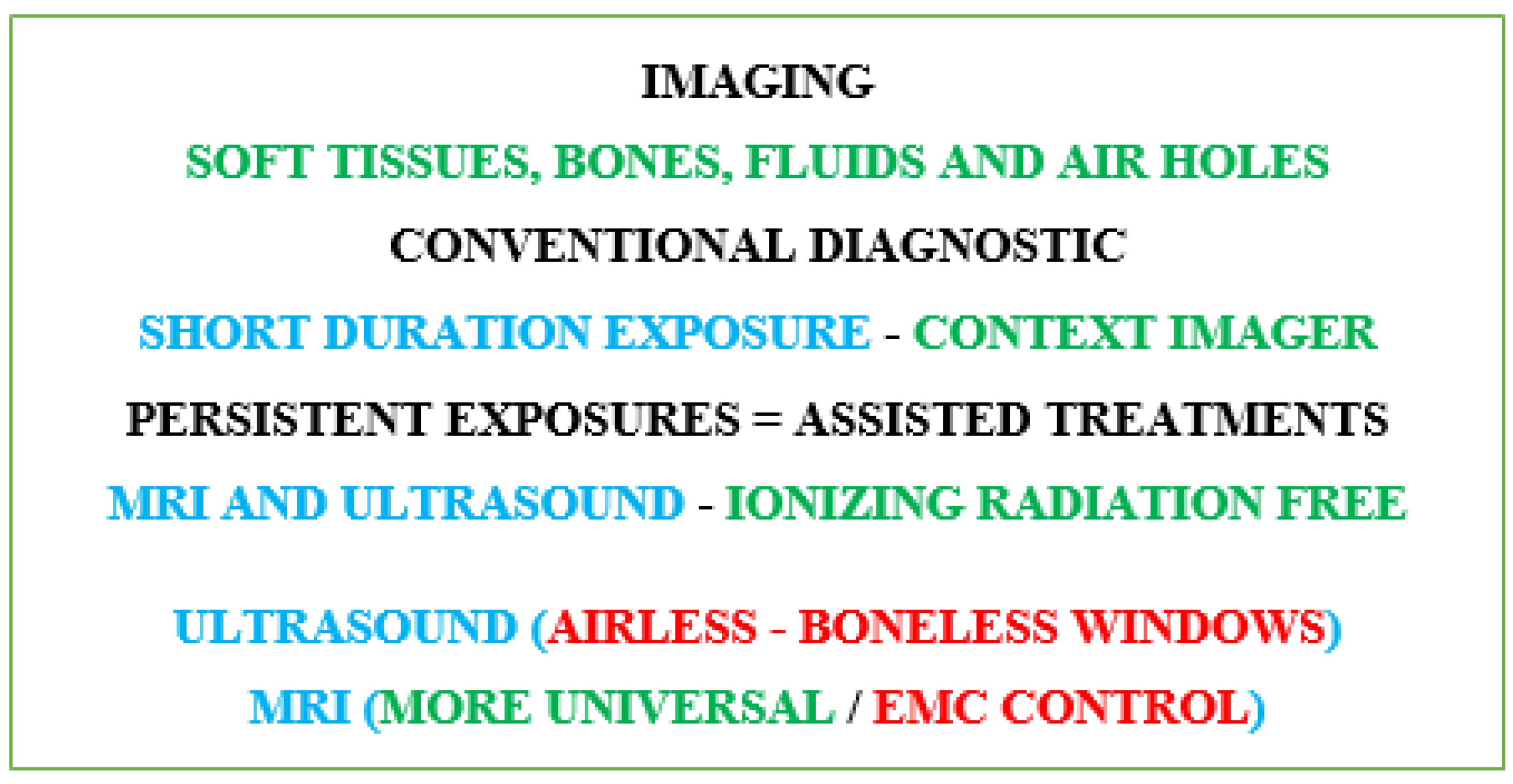
Figure 2.
MRI components and corresponding fields: (a) electromagnet B0 (b) gradient coils (one axis couple) (c) RF coil B1.
Figure 2.
MRI components and corresponding fields: (a) electromagnet B0 (b) gradient coils (one axis couple) (c) RF coil B1.
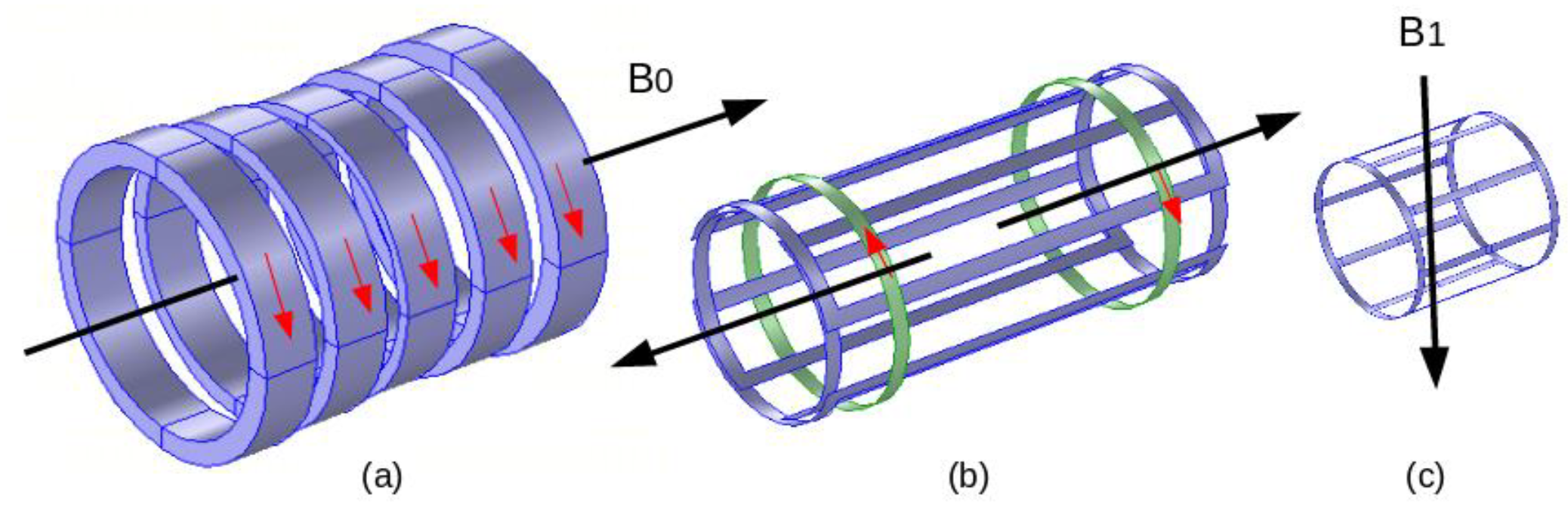
Figure 3.
Summarized representation of the different onboard devices and their functions.
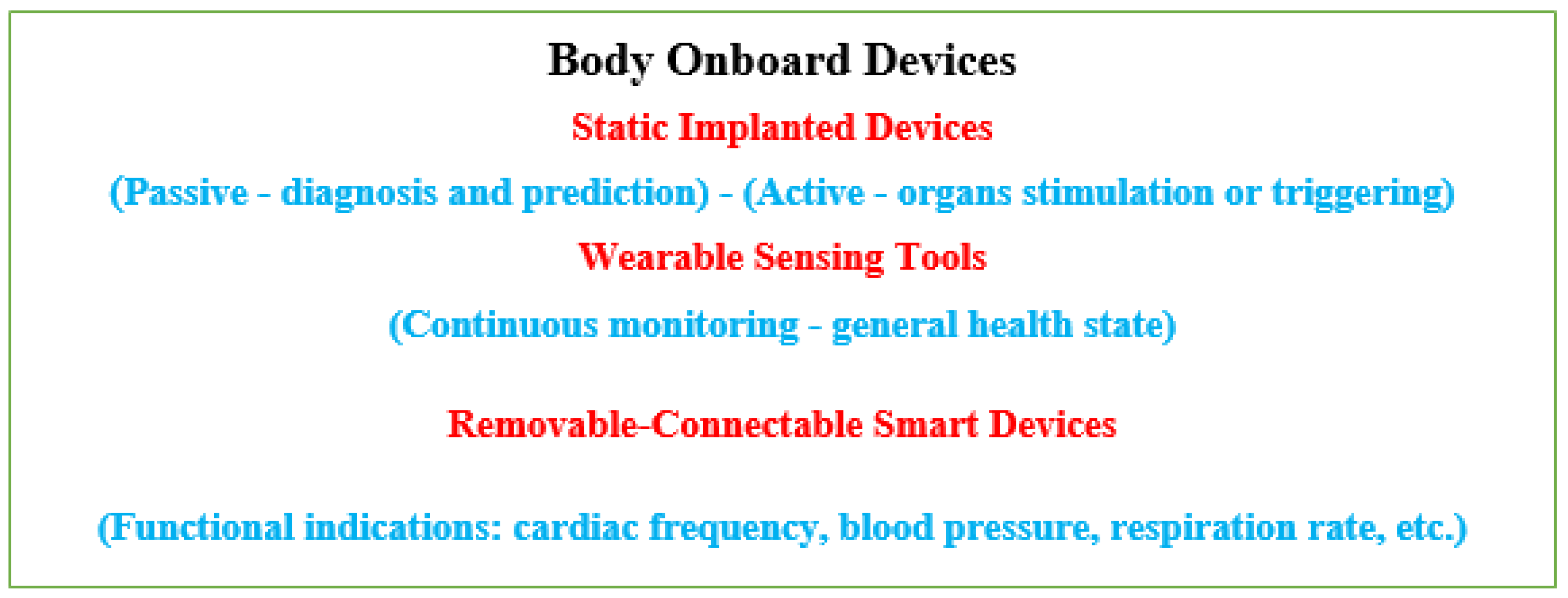
Figure 4.
RF B1 field (vertically directed) distribution in the axial cross section of the birdcage in the tunnel: (a) reference case (b) conductor (c) piezoelectric.
Figure 4.
RF B1 field (vertically directed) distribution in the axial cross section of the birdcage in the tunnel: (a) reference case (b) conductor (c) piezoelectric.
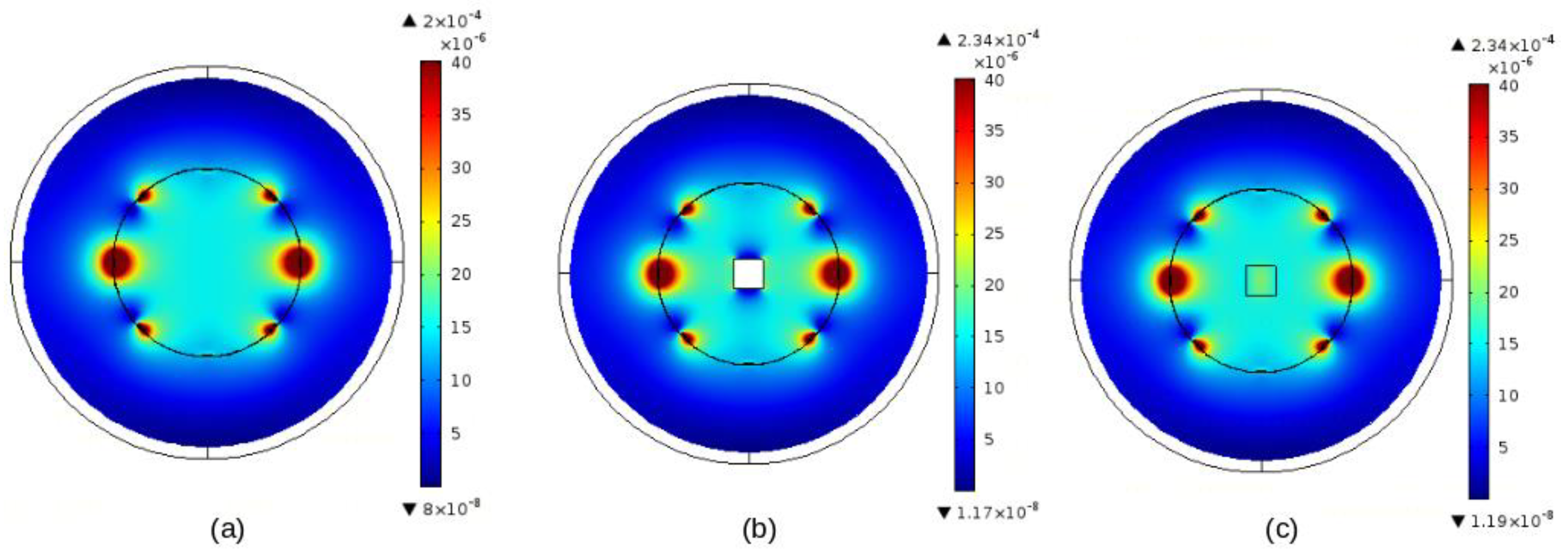
Figure 5.
Illustration of control strategies for onboard devices in case of exposure to EMF (a) Summarized exposure behaviors, (b) Schemes for controlling, the device integrity and the temperature rise in living body tissues.
Figure 5.
Illustration of control strategies for onboard devices in case of exposure to EMF (a) Summarized exposure behaviors, (b) Schemes for controlling, the device integrity and the temperature rise in living body tissues.
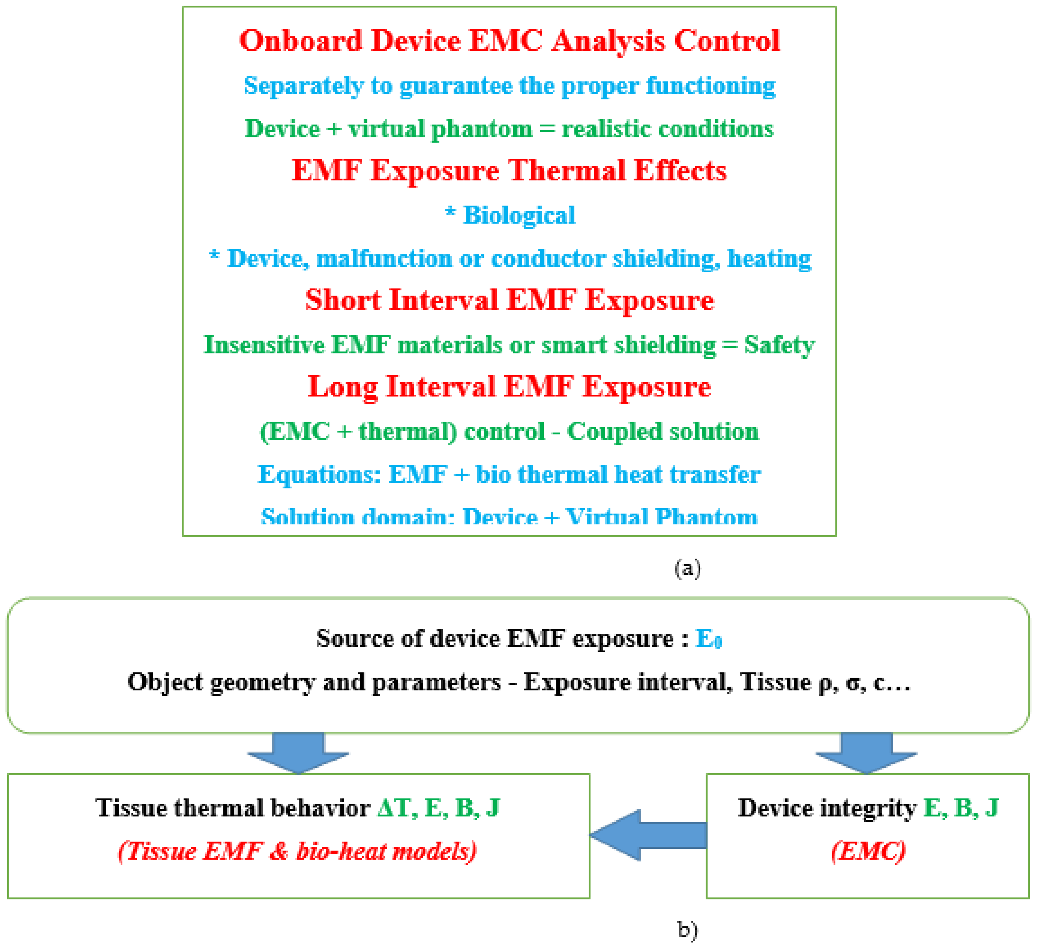
Disclaimer/Publisher’s Note: The statements, opinions and data contained in all publications are solely those of the individual author(s) and contributor(s) and not of MDPI and/or the editor(s). MDPI and/or the editor(s) disclaim responsibility for any injury to people or property resulting from any ideas, methods, instructions or products referred to in the content. |
© 2023 by the authors. Licensee MDPI, Basel, Switzerland. This article is an open access article distributed under the terms and conditions of the Creative Commons Attribution (CC BY) license (http://creativecommons.org/licenses/by/4.0/).
Copyright: This open access article is published under a Creative Commons CC BY 4.0 license, which permit the free download, distribution, and reuse, provided that the author and preprint are cited in any reuse.


