
Submitted:
23 October 2023
Posted:
25 October 2023
You are already at the latest version
Abstract
The analysis of water inflow is a key issue in the construction of subsea tunnels. However, present research on the water inflow of subsea tunnels is predominantly focused on single-bore tunnels. Given the current practices in engineering, it is common to see a parallel configuration of three bores. In such cases, the proximity of tunnels to one another might result in alterations to the water inflow due to the interplay of seepage fields. This paper begins by conducting a numerical simulation to assess the water inflow characteristics of a three-bore parallel subsea tunnel. The study then investigates the impact of many factors, including the permeability coefficient of the surrounding rock, the depth of the seawater, the depth of the tunnel, the spacing between tunnels, and the relative size of the tunnels, on the water inflow phenomenon. Furthermore, based on the principles of the analytic hierarchy process and fuzzy mathematics, a comprehensive assessment framework is developed to evaluate the water inflow of three-bore parallel subsea tunnels. Ultimately, this grade of water inflow is used in practical engineering. The results show that there is mutual influence between the three parallel tunnels, and the predicted water inflow will be too large if the single tunnel model is adopted. The interaction between tunnels should be considered in the water inflow grade evaluation system of the three-hole parallel submarine tunnel. Engineering cases show that using a single-hole tunnel model without considering the interaction between tunnels will lead to higher water inflow grades. The research results of this paper can provide guidance for the waterproofing and drainage design of three parallel subsea tunnels and the stability analysis of surrounding rocks.
Keywords:
Subsea tunnel
; Grading of water inflow
; Three-bore parallel
; Influence between tunnels
; Fuzzy comprehensive evaluation
1. Introduction
Subsea tunnels serve as a crucial expansion of terrestrial transportation networks, playing a significant role in enhancing urban spatial organization and facilitating regional integration and development. Because it can still ensure all-weather traffic during snow, fog, and windy seasons and has little impact on shipping, it has become an important means of crossing rivers and seas [1]. The construction of subsea tunnels necessitates careful attention to the significant issue of sudden water inflow due to the unique water environment. Accurately predicting the water inflow and reasonably evaluating its grade hold significant importance in guiding the waterproof and drainage design of subsea tunnels, as well as the stability analysis of surrounding rocks [2,3,4,5].
Many scholars have conducted in-depth analysis on the problem of underwater tunnel water inflow, proposing research methods such as theoretical analysis, numerical simulation, model experiments, and empirical methods [6,7,8,9]. Qin et al. [10] analyzed the seepage characteristic in a single-bore tunnel with the influence of a grouting ring based on the mirror method proposed by Harr. Furthermore, the theoretical solution was validated and compared with numerical simulations and experimental techniques. Based on the principles of mass conservation and Darcy’s law, Guo et al. [11] investigated the steady-state seepage field of underwater double-bore parallel tunnels by the conformal transformation method and the Schwartz iteration method. Nevertheless, the present analytical solution lacks closure and necessitates implementation via a computational program. Liu et al. [12] posited that the seepage occurring in subsea tunnels adheres to non-Darcy’s law, specifically within the lining and grouting circle, and obtained the analytical solution of the tunnel seepage field under dynamic water levels by complex functions and Hansbo’s non-Darcy seepage model. The analytical method undergoes a rigorous theoretical derivation process, wherein the concepts of parameter physical quantities are clearly defined. Nevertheless, during the calculation procedure, only a limited number of individual attributes are taken into account, such as the permeability coefficient of rock, the depth of the tunnel, and the geometric dimensions of the tunnel. Factors related to water control are disregarded, such as rock joints and fissures, geological structures, and the distribution of strata [13]. Stochastic mathematical methods, including attribute mathematical models, the analytic hierarchy process, and fuzzy extension theory, have been utilized in tunnel engineering to effectively analyze and evaluate the issue of water inflow [14,15]. Despite the inclusion of indicator analysis, weight evaluation, and other processes in the analysis, the evaluation results are widely acknowledged [16]. Katibeh [17] investigated more than 10 different types of tunnels in the Iranian region and summarized 7 factors that affect tunnel water inflow. Based on the concept of geomechanical rock mass rating (RMR), a site groundwater rating method (SGR) was proposed, which divides tunnel water inflow into seven grades based on the danger level of tunnel water inflow. Considering the complexity of the geological environment of the subsea tunnel, Qiu et al. [18] proposed an enhanced grayscale relationship analysis method (GRA), employing an optimal combination weight approach, to evaluate the water inflow risk of the subsea tunnel through faults, selected eight main factors to evaluate and grade the tunnel water inflow, and applied this method to the Qingdao Jiaozhou Bay undersea tunnel project. Maleki et al. [19] utilized the characteristics of joint fissures and hydraulic parameters of rock masses to estimate tunnel water inflow, as demonstrated in their analysis of a Zagros tunnel example. Zarei et al. [20] identified 6 main factors that affect tunnel water inflow based on rock mass characteristics under different geological conditions and combined the analytic hierarchy process (AHP) and statistical methods to estimate tunnel water inflow. Compared with measured data, the rationality and operability of this method were demonstrated.
At present, due to safety and functional requirements, the subsea tunnel usually adopts a three-bore parallel way to cross the strait. However, most of the studies on tunnel seepage phenomena have been conducted using single-tunnel models. When the proximity of tunnels is reduced, the interplay of seepage fields between the tunnels becomes evident, resulting in corresponding alterations in water inflow. Consequently, the utilization of a tunnel seepage model with a single-bore tunnel may result in errors in the estimation of water inflow. This paper proposes a graded evaluation system to assess water inflow in subsea tunnels with three parallel bores and consider the potential impact between the tunnels. At the same time, considering that the hydrogeological environment of the undersea tunnel constitutes a complex system, there are many factors affecting the water inflow of the tunnel, and they interfere with each other. In order to comprehensively analyze and consider the various factors that affect the water inflow of underwater tunnels, the fuzzy comprehensive evaluation method is used to quantitatively process many dynamic and elastic influencing factors and ultimately achieve the prediction and evaluation of tunnel water inflow.
2. Verification of Calculation Models and Methods
2.1. Calculation Model
As shown in Figure 1, the three-bore parallel arrangement of “Main tunnel + Service tunnel” is mostly adopted in subsea tunnels. The simplified calculation model established in this paper is shown in Figure 2. The main tunnel section is a multicenter circular shape with an excavation area of approximately 162.7 m2. The service tunnel has a circular cross-section with an excavation radius of 7.7 m.
In this paper, FLAC 3D software is used to simulate the tunnel seepage field. An isotropic seepage model is employed in the numerical model, with a saturation set to 1.0. The fluid is assumed to have no tensile strength, and a specific hydrostatic pressure is applied to the seabed surface based on the seawater depth. The left, right, and lower boundaries of the model are set as impermeable boundaries. Additionally, the pore water pressure at the inner boundary is assumed to be set to 0 following tunnel excavation. Through trial calculations, the model dimensions were determined as 400 m × 200 m × 1 m, taking into account both solution accuracy and computational efficiency.
2.2. Numerical Method Validation
To validate the accuracy of the numerical calculation method, the double-bore parallel tunnel model introduced in reference [21] is employed for analyzing the seepage field after tunnel excavation. The resultant cloud map of pore water pressure distribution is illustrated in Figure 3. The water inflow for the double-bore tunnel can be computed as Q₁ = Q₂ = 16.52 m³/(m·d), in reference [21], Q1= Q2 = 16.21m3/(m·d), it is evident that the two datasets exhibit fundamental consistency. In conclusion, the numerical calculation method employed in this study is well-founded.
3. Analysis of Factors Affecting Water Inflow
There are many factors that affect the water inflow of tunnels and are difficult to measure. In order to facilitate the grade of water inflow, the first step is to analyze the variation law of water inflow when a single factor changes. For the parallel configuration of three bores within a subsea tunnel, we primarily analyze the influencing factors, including the permeability coefficient of the surrounding rock, seawater depth, tunnel burial depth, as well as the spacing and relative size between the main tunnel and the service tunnel. To illustrate the reciprocal influence among the tunnels, a comparative analysis of the seepage fields between the three-bore tunnel and the single-bore tunnel was conducted.
3.1. Permeability Coefficient
Based on the single factor variable method, the permeability coefficient of the surrounding rock exhibits a range of 0.01 m/d to 0.15 m/d, and the remaining influencing factors are held constant. Figure 4 illustrates the correlation between the permeability coefficient and the tunnel’s water inflow. Whether it is a single-bore tunnel or a main tunnel with three parallel bores, the water inflow exhibits a linear increase in response to the rising permeability coefficient. The water inflow in the main tunnel under the three-bore parallel working condition is comparatively lower than that in the single-bore tunnel under the same conditions. Additionally, the rate at which water inflow increases with changes in the permeability coefficient is also relatively lower in the main tunnel.
3.2. Seawater Depth
Figure 5 illustrates the variation in the water inflow curve as a function of seawater depth. There is a direct linear relationship between the depth of seawater and the corresponding increase in water inflow. Compared to single-bore tunnels, it was observed that the water inflow of a three-bore parallel main tunnel exhibited a lower absolute value and change rate.
3.3. Depth of the Tunnel
Figure 6 illustrates the correlation between the water inflow of the main tunnel and the tunnel burial depth, which is defined as the depth from the seabed to the center of the tunnel. The graph presents this relationship for various rock permeability coefficients. There is a discernible pattern in the water inflow of the main tunnel as the depth of tunnel burial increases. Initially, there is a decrease in water inflow, followed by a subsequent increase. It can be found that there is a critical burial depth hc, which minimizes the water inflow in the tunnel. Furthermore, the figure indicates that variations in the permeability coefficient of the surrounding rock have no significant impact on the critical burial depth. In other words, the critical burial depth of the tunnel appears to be independent of the permeability coefficient of the surrounding rock.
3.4. Tunnel Spacing
Figure 7 illustrates the variation curve of water inflow within the main tunnel as the distance between the main tunnel and the service tunnel is altered. The water inflow of the main tunnel exhibits a gradual increase and converges towards the water inflow of a single-bore tunnel as the distance between the main tunnel and the service tunnel expands from 3r1 to 30r1, where r1 represents the equivalent radius of the multicenter circular section of the main tunnel. It can be determined that the water inflow in the main tunnel is lower than that in the single-bore tunnel when the distance between the main tunnel and the service tunnel falls within a specific range. This trend is particularly evident when the distance between the main and service tunnels is 3r1, the water inflow in the main tunnel amounts to only 63.5% of the water inflow observed in the single-bore tunnel. This observation highlights the mutual influence present in the seepage field between the main tunnel and the service tunnel during the three-bore parallel working condition. An overestimation of the predicted water inflow in the main tunnel is caused by disregarding the interactions between these tunnels.
3.5. Relative size
By maintaining a constant area for the main tunnel while varying the cross-sectional area of the service tunnel, a relationship curve depicting the water inflow of the main tunnel in relation to S2/S1 (the ratio of the service tunnel’s area to the main tunnel’s area) is established, as illustrated in Figure 8. The water inflow of the main tunnel gradually diminishes with the increasing S2/S1 ratio. Notably, as S2/S1 increases from 0 to 1, the water inflow of the main tunnel experiences a reduction of approximately 15%. This underscores the mutual influence existing between tunnels operating under the three-bore parallel condition.
3.6. Analysis of Seepage Field
The examination of influential factors reveals that under the three-bore tunnel working condition, there is a reciprocal influence between the seepage field of the main tunnel and the service tunnel. Consequently, the water inflow into the main tunnel is reduced when compared to a single-bore tunnel under identical circumstances. To investigate the reciprocal impact of tunnels at a profound level, the main tunnel and single-bore tunnel seepage velocity vector maps (Figure 9 and Figure 10) and pore water pressure cloud maps (Figure 11 and Figure 12) are drawn when the stable seepage state is completed after tunnel excavation. The flow velocity vector field around the tunnel presents a symmetrical distribution, and the maximum flow velocity is at the left and right arch foot of the tunnel, with a maximum value of 4.06×10⁻⁷ m/s. Under the parallel working condition of three bores, due to the pressure relief effect of the service tunnel, the seepage velocity at the right arch foot of the main tunnel decreases, and the maximum seepage velocity is only at the left arch foot, with a maximum value of 3.5×10⁻⁷ m/s, the seepage velocity field in the main tunnel exhibits significant asymmetry. From the contour of pore water pressure, it can be seen that under the condition of three parallel bores, due to the mutual pressure relief between tunnels, the pore water pressure of the surrounding rock between tunnels decreases, and the contour becomes sparse. A reduction in the seepage rate and a smaller water inflow of the main tunnel are also explained in terms of the force mechanism.
4. Fuzzy Comprehensive Evaluation System for Tunnel Water Inflow
Fuzzy comprehensive evaluation method is a comprehensive evaluation method based on fuzzy mathematics, which is characterized by clarity and systematicity. This approach converts qualitative assessment into a semi-quantitative assessment, thereby offering an effective solution to address fuzzy and challenging problems that are difficult to quantify. Many factors influence the water inflow in tunnels, and the classification of water inflow grades is primarily based on single-bore tunnel scenarios. To consider the mutual influence of tunnels with three bores in parallel working conditions, the fuzzy comprehensive evaluation method is used to establish a grade model of water inflow, hoping to get a water inflow evaluation method suitable for the tunnel with three bores in parallel.
4.1. Establishment of Evaluation set and Evaluation Factor Set
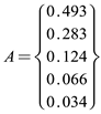
Compose a common set of factors that affect tunnel water inflow, called the factor set, represented by A, as shown in equation (1):

Where,  represents the factors that affect the water inflow in the tunnel, and these factors exhibit a certain degree of fuzziness.
represents the factors that affect the water inflow in the tunnel, and these factors exhibit a certain degree of fuzziness.At the same time, the evaluation results of tunnel water inflow will be formed into a general set B, as shown in equation (2):

Where,  represents the evaluation results of tunnel water inflow when various factors affecting tunnel water inflow occur. According to the actual engineering situation, the evaluation set is divided into 5 grades: very severe, severe, relatively severe, slightly severe, and mild, represented by V, IV, III, II, and I levels, as shown in Table 1.
represents the evaluation results of tunnel water inflow when various factors affecting tunnel water inflow occur. According to the actual engineering situation, the evaluation set is divided into 5 grades: very severe, severe, relatively severe, slightly severe, and mild, represented by V, IV, III, II, and I levels, as shown in Table 1. 4.2. Evaluation Index System of Water Inflow
In this paper, indicators of influencing factors are determined with a combination of survey, design, and construction. A selection has been made for 5 first-level indicators, encompassing the physical-mechanical characteristics of surrounding rock (A1), hydrogeological conditions of tunnel engineering (A2), geometric characteristics of tunnel engineering (A3), tunnel construction methods (A4), and tunnel profile shape (A5). For the physical-mechanical characteristics of surrounding rock, the main considerations are the surrounding rock grades (A11), the degree of joint fissures development (A12), rock mass integrity index (A13), and rock weathering degree (A14). For the hydrogeological conditions of tunnel engineering, the soil permeability coefficient (A21), seawater depth (A22), and tunnel burial depth (A23) are mainly considered. The relative size (A31) and tunnel spacing (A32) are analyzed for the geometric characteristics of the tunnel. In tunnel construction methods, the impact of shield tunneling (A41) and drilling and blasting method (A42) on tunnel water inflow are considered. In cavity shape analysis, differences in multicenter circular section (A51) and circular section (A51) water inflow are examined. The tunnel water inflow evaluation indicator system is shown in Table 2.
4.3. Establishment of Index Weights
The index weight is a quantitative measure that signifies the significance of different factors influencing tunnel water inflow. These factors are assigned numerical values ranging from 0 to 1. As the value increases, the weight of factor also increases, resulting in a greater influence on the evaluation set. The weights assigned to each factor in the final analysis consistently adhere to the normalization principle, wherein the sum of all weights equals 1.
In the fuzzy comprehensive evaluation method, the determination of factor weights is of utmost importance. This is typically achieved through the utilization of expert evaluation methods and the analytic hierarchy process. The analytic hierarchy process is a methodology that breaks down a problem into various constituent factors, taking into consideration its inherent characteristics and overarching objective. These factors are then aggregated and structured into a multi-level analytical framework, taking into account their interrelationships and hierarchy. This process ultimately leads to the determination of relative importance weights or the ranking of factors in terms of their relative superiority or inferiority, with respect to the highest-level goal.
The general steps of analytic hierarchy process are:
(a) The initial step in the analytic hierarchy process involves establishing a hierarchical structure. The primary goal is to provide a clear definition of the target problem, identify relevant influencing factors, construct a hierarchical framework of these factors, and subsequently develop an evaluation system encompassing the entirety of the problem;
(b) In order to assess the relative significance of factors at the same level, it is recommended to employ scale values. These scale values can be used to construct a correlation judgment matrix. The significance of scale is demonstrated in Table 3;
(c) Calculate the eigenvalues and eigenvectors of the matrix, and after normalization, obtain the weight values of the corresponding factors;
(d) Conduct consistency check, calculate the consistency index CI using equation (3), determine the average random consistency index from Table 4, and calculate the consistency ratio CR using equation (4). When the calculation result CR < 0.1, it is considered that the consistency of the judgment matrix is acceptable.

Where, λmax is the maximum eigenvalue of the correlation judgment matrix, and n is the order of the matrix.

In the process of establishing a judgment matrix, the three principles of objectivity, directionality, and measurability are followed. The specific analysis of indicator layer weights and criterion layer weights in this paper is as follows:
- (1)
- Weight analysis of indicator layer
The weight judgment matrix for the physical-mechanical characteristics of surrounding rock is shown in Table 5. Assuming that the maximum eigenvalue of this matrix is λmax and the corresponding eigenvector is η, Through calculation, it can be obtained that: λmax = 4.061, η = [0.393, 0.158, 0.39]T, η is the weight; Simultaneously, the consistency ratio  can be calculated from equations (3) and (4) and passes the consistency test. Similarly, other indicator layer parameters can be calculated, as shown in Table 6, Table 7, Table 8 and Table 9.
can be calculated from equations (3) and (4) and passes the consistency test. Similarly, other indicator layer parameters can be calculated, as shown in Table 6, Table 7, Table 8 and Table 9.- (2)
- Weight analysis of criteria layer
4.4. Membership Function
In this paper, the trapezoidal membership function in the univariate linear membership function is used to establish the membership degree of evaluation indicators. The general mathematical model is shown in Figure 13.
4.5. Multi-Factor Fuzzy Evaluation
By fuzzy transformation between the single factor evaluation matrix and the weight set, the results of the fuzzy comprehensive evaluation model can be obtained, as shown in equation (5).
where, T is the fuzzy evaluation vector, A is the weight set vector, and R is the single factor evaluation matrix. According to the principle of maximum membership, the position of the maximum value in the vector T is the grade of water inflow under this working condition.
T = AR
5. Engineering Application of Graded Evaluation of Water Inflow
To validate the applicability of the fuzzy comprehensive evaluation system for water inflow, a case study was conducted using a three-bore parallel subsea tunnel project as an example to assess the grading of water inflow. To explore the mutual influence between tunnels, the grade of water inflow is divided into two situations: (a) considering the mutual influence between tunnels, the evaluation indicators include tunnel geometric characteristics (tunnel spacing and relative size); (b) Without considering the mutual influence between tunnels, the water inflow grade is based on a single-bore tunnel.
- (1)
- Considering the mutual influence between tunnels
The weight of evaluation indicators is firstly calculated and the corresponding evaluation matrix is obtained by a trapezoidal membership function. Multiplying the weight of the indicator layer by the corresponding evaluation matrix can obtain the fuzzy matrix of the indicator layer. The specific calculation results are shown in Table 12.
Based on this, the fuzzy matrix of the water inflow criteria layer of the main tunnel can be obtained in the case of three parallel bores:
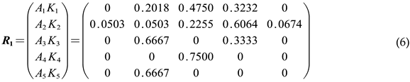
By substituting R1 into equation (5), the evaluation vector T1 = (0.0420 0.2193 0.3471 0.3725 0.0191) can be obtained. The maximum value in the T1 vector is 0.3725, which is in the fourth place. Based on the principle of maximum membership, the judgment is made, taking into account the mutual influence between tunnels. Under this working condition, the water inflow is level IV.
- (2)
- Not considering the mutual influence between tunnels
Adopting a single-bore tunnel model, without considering the mutual influence between tunnels, the evaluation indicators remove the geometric features of tunnels (tunnel spacing and relative size), and still use the fuzzy comprehensive evaluation method to grade the water inflow of tunnels under the same conditions, obtaining the fuzzy matrix of the criteria layer:

Substitute R2 into equation (5) to obtain the evaluation vector T2 = (0.0527 0.1590 0.4038 0.3643 0.0202). Based on the principle of maximum membership, without considering the mutual influence between tunnels, the water inflow under the same conditions is level III.
6. Conclusions
This paper focuses on a three-bore parallel subsea tunnel as its research subject. By conducting a single-factor analysis of water inflow, the study employs the Analytic Hierarchy Process and Fuzzy Evaluation Method to create a comprehensive fuzzy evaluation system for water inflow. The system is then applied to engineering scenarios. The main conclusions were as follows:
- (1)
- Under the condition of three parallel tunnels, the water inflow increases linearly with the rise in permeability coefficient and seawater depth. As the burial depth increases, it exhibits a trend of initially decreasing and then increasing. The water inflow rises with an increase in tunnel spacing, approaching the water inflow of a single-bore tunnel. Conversely, it decreases with an increase in the relative size between the service tunnel and the main tunnel.
- (2)
- Under the condition of three parallel bores, there is mutual influence in the seepage field between subsea tunnels, which leads to a decrease in pore water pressure and a decrease in seepage velocity between tunnels. Using a single-bore tunnel model can lead to a higher predicted value of tunnel water inflow.
- (3)
- The water inflow evaluation system constructed based on the fuzzy comprehensive evaluation method can quantitatively process various influencing factors and achieve the classification of water inflow grades.
- (4)
- In the grading evaluation system of water inflow for three-bore parallel subsea tunnels, the mutual influence between tunnels should be considered. Engineering cases have shown that using a single-bore tunnel model without considering the mutual influence between tunnels can lead to an increase in the grade of water inflow.
Author Contributions
Conceptualization, Z.H. and Z.Z.; Methodology, Z.H. and K.Y.; Software, K.Y.; Validation, Z.H. and K.Y.; Formal analysis, Z.H. and K.Y.; Data Curation, K.Y.; Writing, original draft preparation, Z.H. and K.Y.; Writing, review and editing, Z.H. and K.Y.; Visualization, H.C.; Supervision, Z.Z.; Funding acquisition, Z.H. and Z.Z. All authors have read and agreed to the published version of the manuscript.
Funding
The research described in this paper was financially supported by the General Program of National Natural Science Foundation of China (Grant No.: 51978424), the Innovation Research Group Project of Natural Science Foundation of Hebei Province of China (Grant No.: E2022210078), the S&T Program of Hebei Province in China (Grant No.: 22375416D), and the General Program of Natural Science Foundation of Hebei Province of China (Grant No.: E2022210040).
Institutional Review Board Statement
Not applicable.
Data Availability Statement
The data presented in this study are available upon request from the corresponding author.
Conflicts of Interest
The authors declare no conflict of interest.
References
- Fang, Q., Song, H., & Zhang, D. (2015). Complex variable analysis for stress distribution of an underwater tunnel in an elastic half plane. International Journal for Numerical and Analytical Methods in Geomechanics, 39(16), 1821–1835. [CrossRef]
- Cividini, A., Contini, A., Locatelli, L., & Gioda, G. (2012). Investigation on the Cause of Damages of a Deep Tunnel. International Journal of Geomechanics, 12(6), 722–731. [CrossRef]
- Zareifard, M. R., & Fahimifar, A. (2015). Elastic–Brittle–Plastic Analysis of Circular Deep Underwater Cavities in a Mohr-Coulomb Rock Mass Considering Seepage Forces. International Journal of Geomechanics, 15(5), 04014077. [CrossRef]
- Qiu, D., Chen, Q., Xue, Y., Su, M., Liu, Y., Cui, J., & Zhou, B. (2022). A new method for risk assessment of water inrush in a subsea tunnel crossing faults. Marine Georesources & Geotechnology, 40(6), 679–689. [CrossRef]
- Farhadian, H., & Katibeh, H. (2017). New empirical model to evaluate groundwater flow into circular tunnel using multiple regression analysis. International Journal of Mining Science and Technology, 27(3), 415–421. [CrossRef]
- Katibeh, H., & Aalianvari, A. (2009). Development of a New Method for Tunnel Site Rating from Groundwater Hazard Point of View. Journal of Applied Sciences, 9(8), 1496–1502. [CrossRef]
- Farhadian, H., & Nikvar-Hassani, A. (2019). Water flow into tunnels in discontinuous rock: A short critical review of the analytical solution of the art. Bulletin of Engineering Geology and the Environment, 78(5), 3833–3849. [CrossRef]
- Ying, H.-w., Zhu, C.-w., Shen, H.-w., & Gong, X.-n. (2018). Semi-analytical solution for groundwater ingress into lined tunnel. Tunnelling and Underground Space Technology, 76, 43–47. [CrossRef]
- Zarei, H.R., Uromeihy, A., & Sharifzadeh, M. (2013). A new tunnel inflow classification (TIC) system through sedimentary rock masses. Tunnelling and Underground Space Technology, 34, 1–12. [CrossRef]
- Hwang, J.-H., & Lu, C.-C. (2007). A semi-analytical method for analyzing the tunnel water inflow. Tunnelling and Underground Space Technology, 22(1), 39–46. [CrossRef]
- Li, L., Lei, T., Li, S., Zhang, Q., Xu, Z., Shi, S., & Zhou, Z. (2015). Risk assessment of water inrush in karst tunnels and software development. Arabian Journal of Geosciences, 8(4), 1843–1854. [CrossRef]
- Maleki, M.R. (2018). Groundwater Seepage Rate (GSR); a new method for prediction of groundwater inflow into jointed rock tunnels. Tunnelling and Underground Space Technology, 71, 505–517. [CrossRef]
- Golian, M., Sharifi Teshnizi, E., & Nakhaei, M. (2018). Prediction of water inflow to mechanized tunnels during tunnel-boring-machine advance using numerical simulation. Hydrogeology Journal, 26(8), 2827–2851. [CrossRef]
- Cheng, P., Zhao, L., Li, Q., Li, L., & Zhang, S. (2019). Water Inflow Prediction and Grouting Design for Tunnel considering Nonlinear Hydraulic Conductivity. KSCE Journal of Civil Engineering, 23(9), 4132–4140. [CrossRef]
- Qin, Z., He, W., & Zhou, H. (2022). Analytical study on seepage field of subsea twin tunnels constructed by NATM. Ocean Engineering, 264, 112345. [CrossRef]
- Li, S.-c., Liu, H.-l., Li, L.-p., Zhang, Q.-q., Wang, K., & Wang, K. (2016). Large scale three-dimensional seepage analysis model test and numerical simulation research on undersea tunnel. Applied Ocean Research, 59, 510–520. [CrossRef]
- Li, S.-c., He, P., Li, L.-p., Shi, S.-s., Zhang, Q.-q., Zhang, J., & Hu, J. (2017). Gaussian process model of water inflow prediction in tunnel construction and its engineering applications. Tunnelling and Underground Space Technology, 69, 155–161. [CrossRef]
- Ho, W., & Ma, X. (2018). The state-of-the-art integrations and applications of the analytic hierarchy process. European Journal of Operational Research, 267(2), 399–414. [CrossRef]
- Liu, X., Wang, D., Zhang, Y., Jiang, A., Fang, Q., & Zhang, R. (2023). Analytical solutions on non-Darcy seepage of grouted and lined subsea tunnels under dynamic water levels. Ocean Engineering, 267, 113276. [CrossRef]
- Guo, Y.F., Wang, H.N., & Jiang, M.J. (2023). An exact analytical approach for determining the seepage field around underwater twin tunnels with linings. Transportation Geotechnics, 42, 101050. [CrossRef]
- Qin, Z., Wang, Y., Song, Y., & Dong, Q. (2020). The Analysis on Seepage Field of Grouted and Shotcrete Lined Underwater Tunnel. Mathematical Problems in Engineering, 2020, 1–15. [CrossRef]
Figure 1.
Three-bore parallel subsea tunnel.
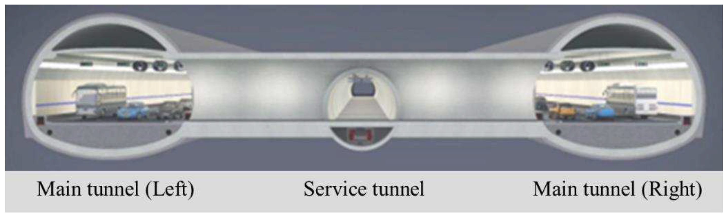
Figure 2.
Computational model for seepage field in three-bore parallel subsea tunnels.
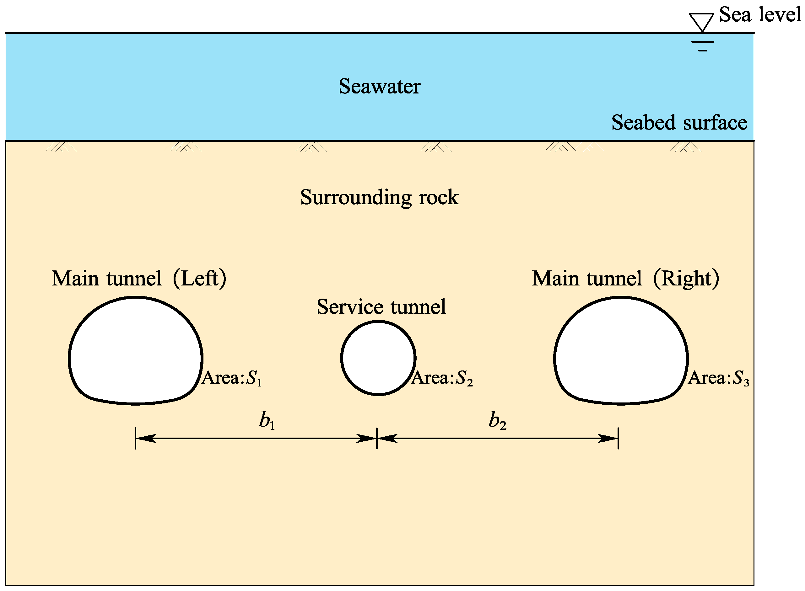
Figure 3.
Pore water pressure distribution (unit: kPa).
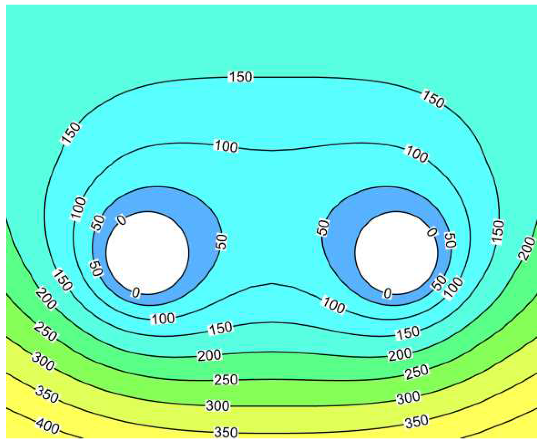
Figure 4.
Relation between permeability coefficient of surrounding rock and water inflow.
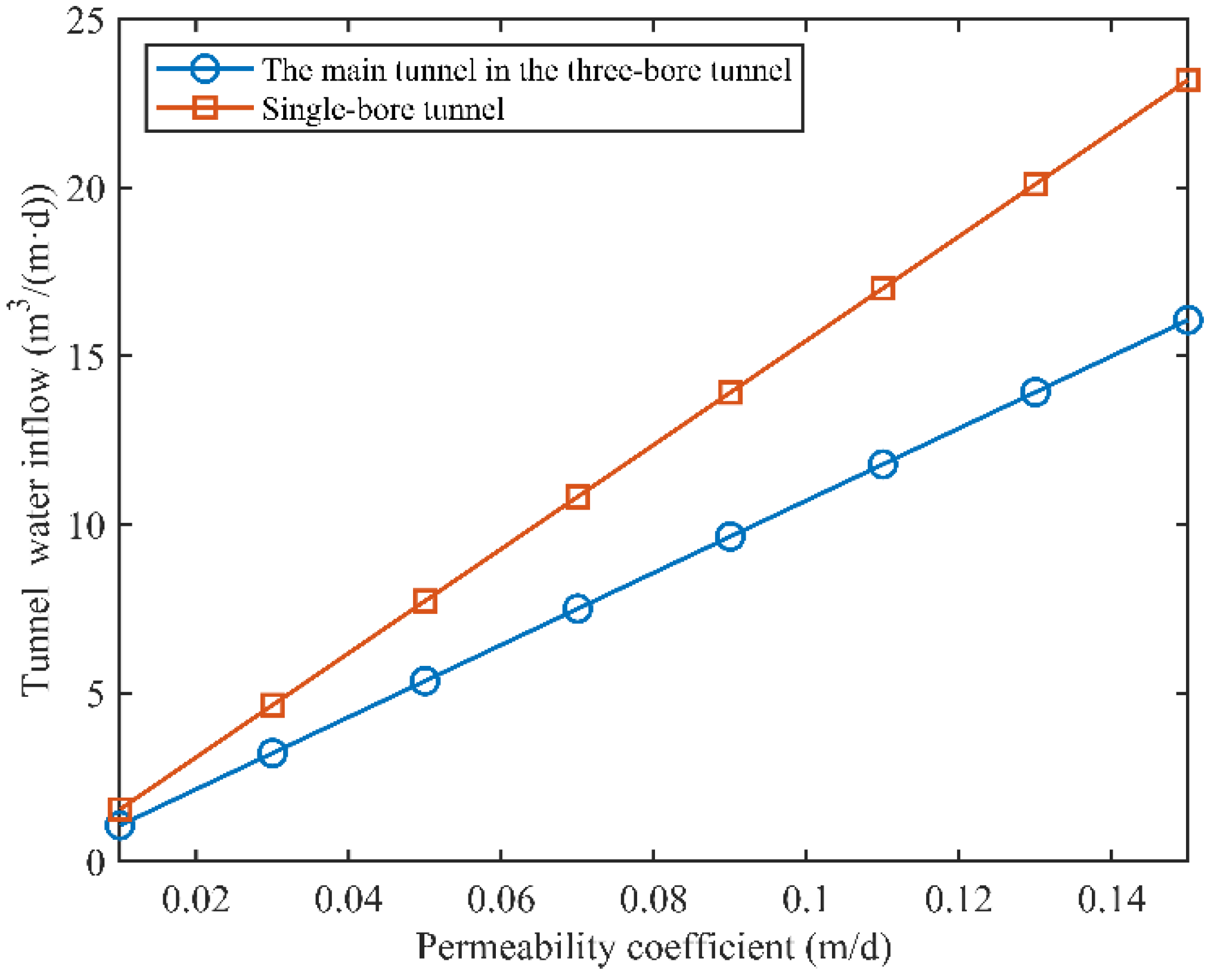
Figure 5.
Change of water inflow with seawater depth.
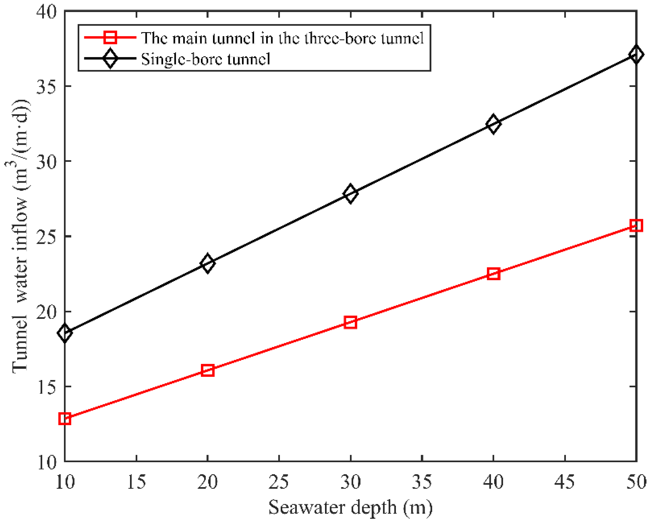
Figure 6.
Relation between depth of the tunnel and water inflow.
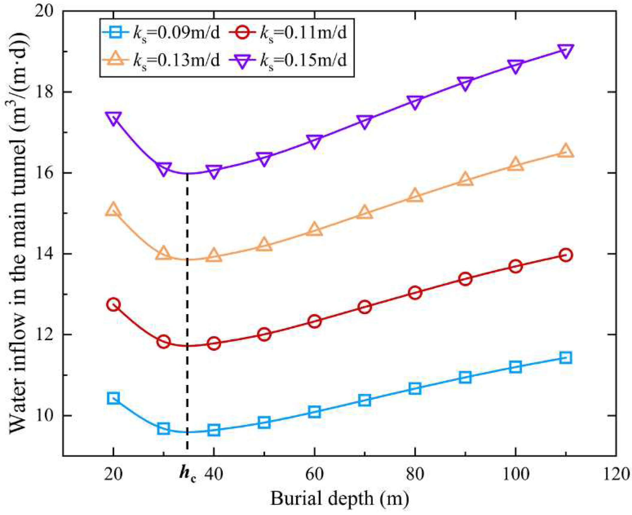
Figure 7.
Relation between tunnel spacing and water inflow.
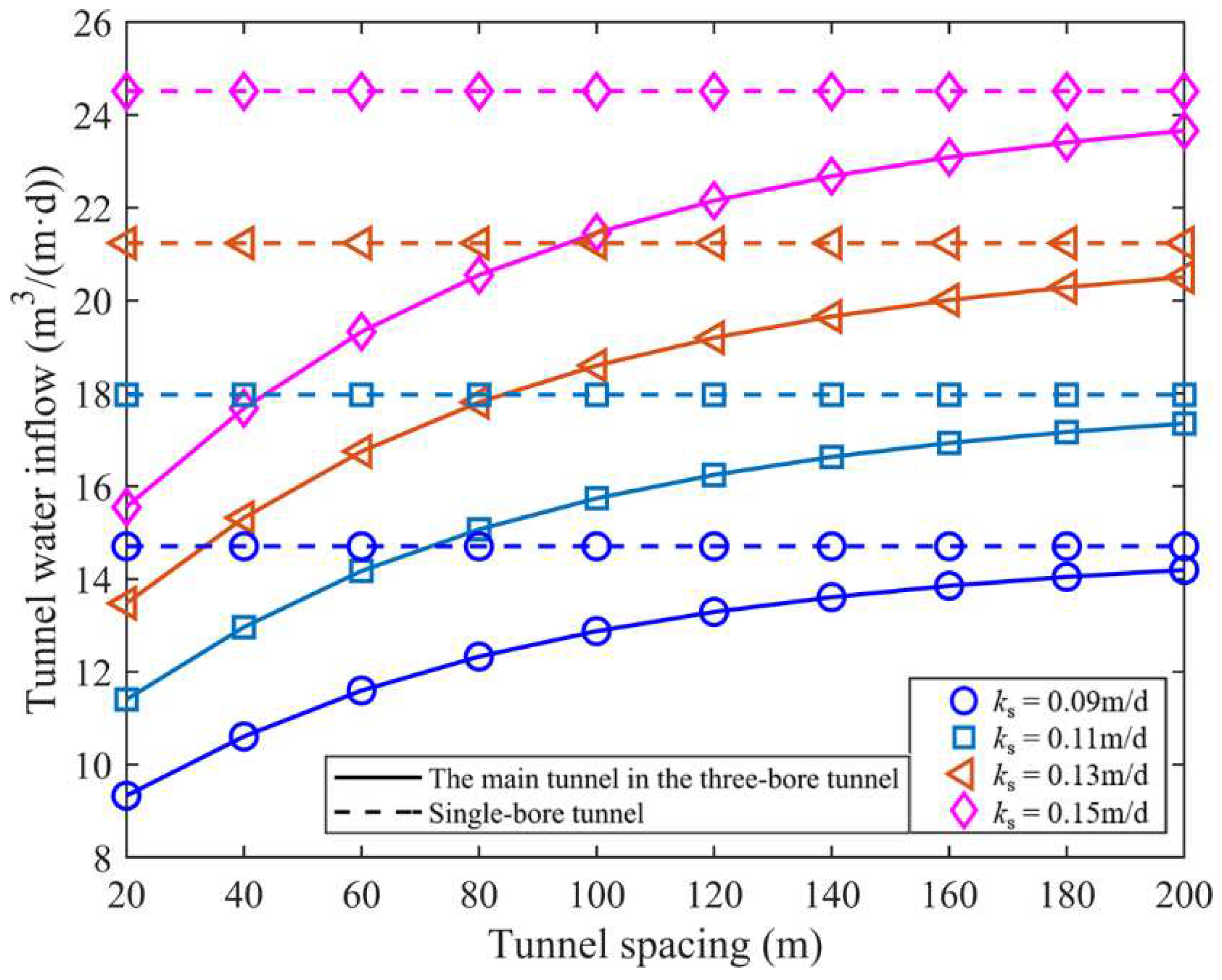
Figure 8.
Relation S2/S1 and water inflow of main tunnel.
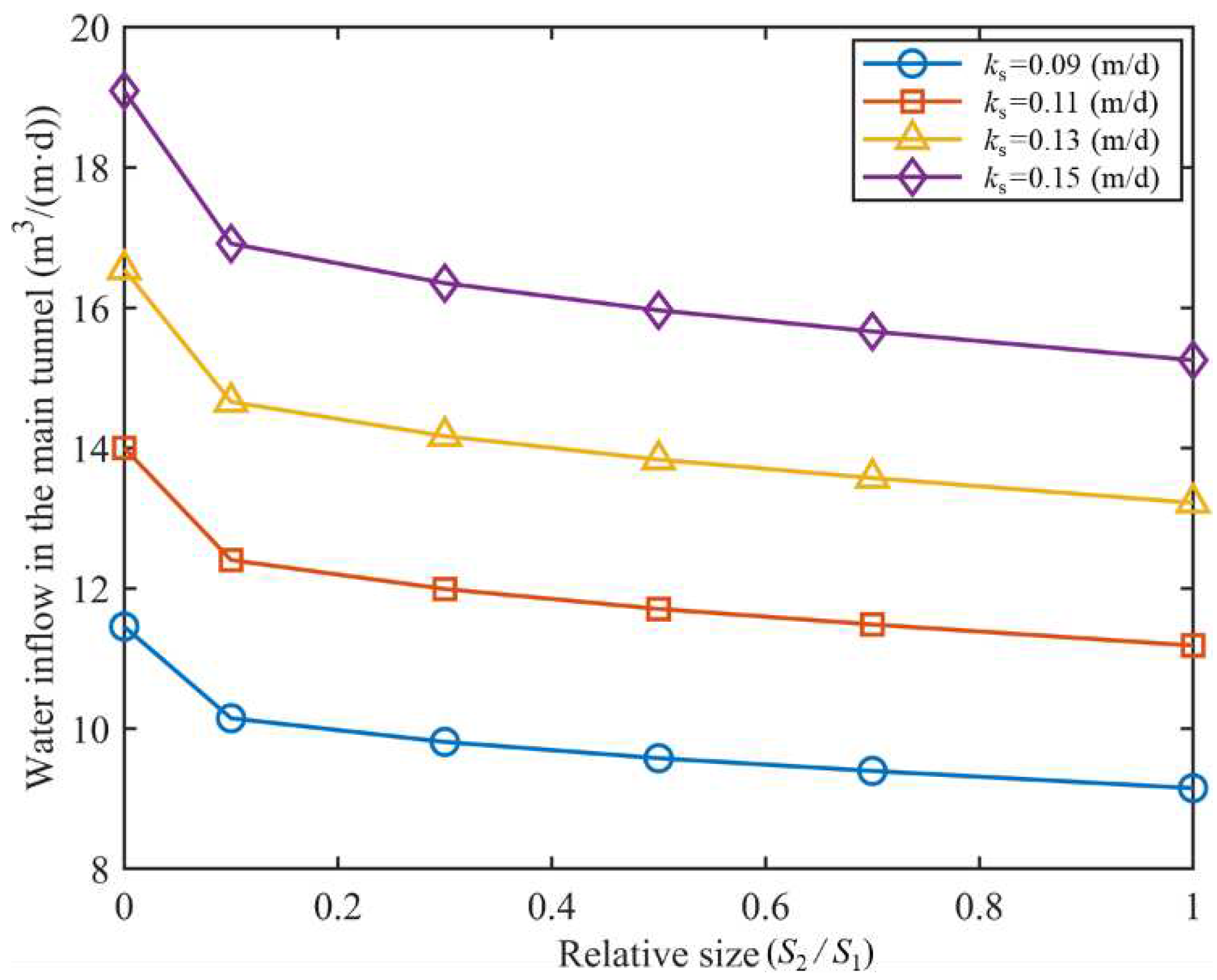
Figure 9.
Seepage velocity of the main tunnel in a three-bore parallel tunnel.
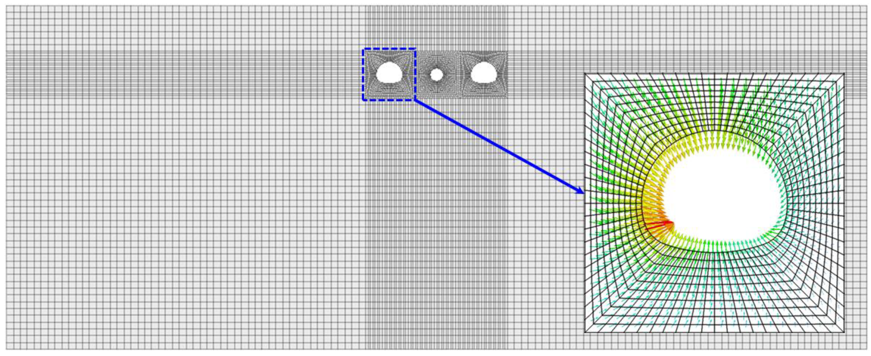
Figure 10.
Seepage velocity of single-bore tunnel.
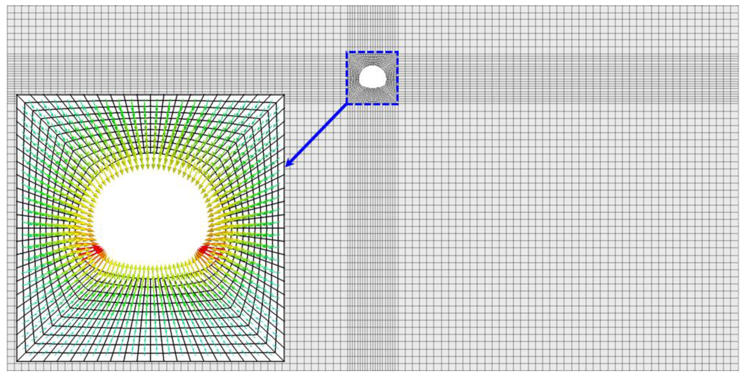
Figure 11.
Distribution of pore water pressure in a three-bore tunnel (unit: kPa)
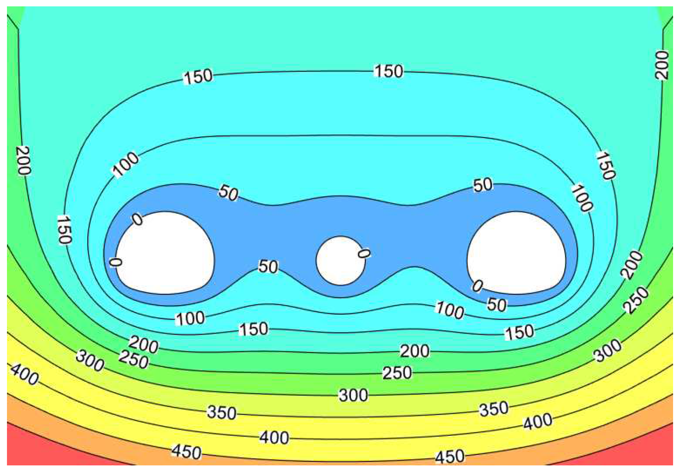
Figure 12.
Distribution of pore water pressure in a single-bore tunnel (unit: kPa).
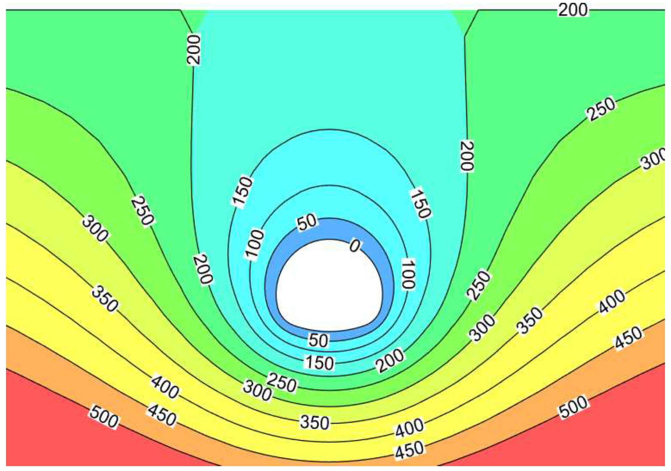
Figure 13.
Trapezoidal membership function.
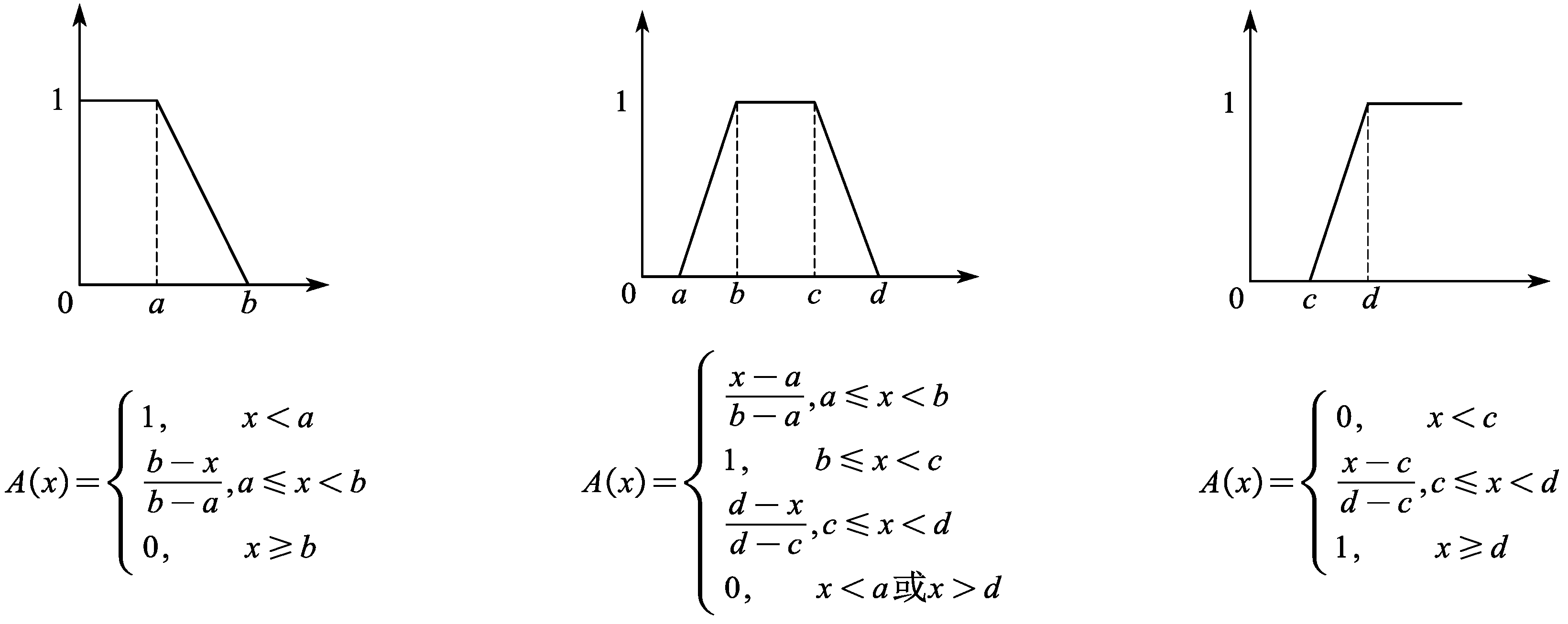

Table 1.
Classification of tunnel water inflow grades.
| Water Inflow Grade | Water Inflow Evaluation |
| Ⅰ | Mild (Generally no risk of inrush) |
| Ⅱ | Slightly severe (Possible occurrence of fissure inrush) |
| Ⅲ | Relatively severe (Possible occurrence of localized inrush) |
| Ⅳ | Severe (Possible occurrence of localized inrush) |
| Ⅴ | Very severe (Possible occurrence of large-scale inrush) |
Table 2.
Evaluation index system for tunnel water inflow.
| Target Layer | Criteria Layer | Indicator Layer | Assessment Of Water Inflow | ||||
| Ⅰ | Ⅱ | Ⅲ | Ⅵ | Ⅴ | |||
| Grade standard for water inflow in subsea tunnels | Physical-mechanical characteristics of surrounding rock | Surrounding rock grades | Ⅰ、Ⅱ | Ⅲ | Ⅳ | Ⅴ | Ⅵ |
| Joint fissures development degree | Undeveloped | Moderately developed | Developed | Highly developed | Disordered | ||
| Rock mass integrity index(Kv) | Kv > 0.75 | 0.75 ≥Kv > 0.55 | 0.55 ≥Kv > 0.35 | 0.35 ≥Kv > 0.15 | Kv < 0.15 | ||
| Rock weathering degree | Unweathered | Slightly weathered | Moderately weathered | Highly weathered | Completely weathered | ||
| Hydrogeological conditions of tunnel engineering | Permeability coefficient (m/d) | < 0.01 | 0.01 ~ 0.05 | 0.05 ~ 0.1 | 0.1 ~ 0.15 | > 0.15 | |
| Seawater depth (m) | < 10 | 10 ~ 20 | 20 ~ 30 | 30 ~ 40 | 40 ~ 50 | ||
| Tunnel burial depth (m) | 20 ~ 40 | 40 ~ 60 | 60 ~ 80 | 80~100∪ 10 ~ 20 |
< 10∪ >100 |
||
| Geometric characteristics of tunnel engineering | Relative size | > 1 | 0.1 ~ 1.0 | 0.3 ~ 0.7 | 0.1 ~ 0.4 | < 0.1 | |
| Tunnel spacing (m) | < 25 | 25 ~ 50 | 50 ~ 75 | 75 ~ 100 | > 100 | ||
| Tunnel construction methods | Drilling and blasting method | — | — | Drilling and blasting method | — | — | |
| Shield method | Shield method | — | — | — | — | ||
| Tunnel profile shape | Multicenter circular | — | Multicenter circular | — | — | — | |
| Circular | Circular | — | — | — | — | ||
Table 3.
Scale of relative importance.
| Scale (aij) | Definition |
| 1 | When comparing two factors, factor i is equally important as factor j |
| 3 | When comparing two factors, factor i is slightly more important than factor j |
| 5 | When comparing two factors, factor i is more important than factor j |
| 7 | When comparing two factors, factor i is significantly more important than factor j |
| 9 | When comparing two factors, factor i is absolutely more important than factor j |
| 2、4、6、8 | The comparison results of the importance between factors i and j fall within the ranges of 1-3, 3-5, 5-7, and 7-9. |
| reciprocal | The comparison results of the importance between factors j and i are reciprocals of the comparison results between factors i and j |
Table 4.
Average random consistency indicators.
| n | 1 | 2 | 3 | 4 | 5 | 6 | 7 | 8 | 9 | 10 |
| RI | 0 | 0 | 0.52 | 0.89 | 1.12 | 1.26 | 1.36 | 1.41 | 1.46 | 1.49 |
Table 5.
Weight judgment matrix for the physical-mechanical characteristics of the surrounding rock.
Table 5.
Weight judgment matrix for the physical-mechanical characteristics of the surrounding rock.
| Physical-Mechanical Characteristics Of Surrounding Rock A1 | A11 | A12 | A13 | A14 | Weight | CR |
| Surrounding rock grades (A11) | 1 | 3 | 1 | 6 | 0.393 | 0.03 |
| Joint fissures development degree (A12) | 1/3 | 1 | 1/3 | 4 | 0.158 | |
| Rock mass integrity index (A13) | 1 | 3 | 1 | 6 | 0.393 | |
| Rock weathering degree (A14) | 1/6 | 1/4 | 1/6 | 1 | 0.056 |
Table 6.
Weight judgment matrix for tunnel engineering hydrogeological conditions.
| Hydrogeological Conditions Of Tunnel Engineering A2 | A21 | A22 | A23 | Weight | CR |
| Permeability coefficient (A21) | 1 | 4 | 5 | 0.674 | 0.08 |
| Seawater depth (A22) | 1/4 | 1 | 3 | 0.226 | |
| Tunnel burial depth (A23) | 1/5 | 1/3 | 1 | 0.100 |
Table 7.
Weight judgment matrix for tunnel geometric characteristics.
| Geometric Characteristics Of Tunnel Engineering A3 | A31 | A32 | Weight | CR |
| Relative size (A31) | 1 | 1/2 | 0.333 | 0 |
| Tunnel spacing (A32) | 2 | 1 | 0.667 |
Table 8.
Weight judgment matrix for tunnel engineering construction methods.
| Tunnel Construction Methods A4 | A41 | A42 | Weight | CR |
| Drilling and blasting method (A41) | 1 | 3 | 0.750 | 0 |
| Shield method (A42) | 1/3 | 1 | 0.250 |
Table 9.
Weight judgment matrix for tunnel profile shape.
| Tunnel Profile Shape A5 | A51 | A52 | Weight | CR |
| Multicenter circular (A51) | 1 | 2 | 0.667 | 0 |
| Circular (A52) | 1/2 | 1 | 0.333 |
Table 10.
Criterion layer weight analysis.
| Grade Of Water Inflow In Subsea Tunnels | A1 | A2 | A3 | A4 | A5 | Weight | CR |
| Physical-mechanical characteristics of surrounding rock (A1) | 1 | 3 | 5 | 6 | 8 | 0.493 | 0.07 |
| Hydrogeological conditions of tunnel engineering (A2) | 1/3 | 1 | 4 | 5 | 7 | 0.283 | |
| Geometric characteristics of tunnel engineering (A3) | 1/5 | 1/4 | 1 | 3 | 5 | 0.124 | |
| Tunnel construction methods (A4) | 1/6 | 1/5 | 1/3 | 1 | 3 | 0.066 | |
| Tunnel profile shape (A5) | 1/8 | 1/7 | 1/5 | 1/3 | 1 | 0.034 |
Table 11.
Criteria layer and indicator layer weight sets.
| Criteria Layer | Weight | Criteria Layer Weight Set | Indicator Layer | Weight | Indicator Layer Weight Set |
|---|---|---|---|---|---|
| Physical-mechanical characteristics of surrounding rock | 0.493 |
 |
Surrounding rock grades | 0.393 |  |
| Joint fissures development degree | 0.158 | ||||
| Rock mass integrity index | 0.393 | ||||
| Rock weathering degree | 0.056 | ||||
| Hydrogeological conditions of tunnel engineering | 0.283 | Permeability coefficient | 0.674 |  |
|
| Seawater depth | 0.226 | ||||
| Tunnel burial depth | 0.100 | ||||
| Geometric characteristics of tunnel engineering | 0.124 | Relative size | 0.333 |  |
|
| Tunnel spacing | 0.667 | ||||
| Tunnel construction methods | 0.066 | Drilling and blasting method | 0.750 |  |
|
| Shield method | 0.250 | ||||
| Tunnel profile shape | 0.034 | Multicenter circular | 0.667 |  |
|
| Circular | 0.333 |
Table 12.
Calculation results of i indicator layer fuzzy matrix.
| Parameters | Grades | Evaluation Matrix | ||||
| Ⅰ | Ⅱ | Ⅲ | Ⅳ | Ⅴ | ||
| Surrounding rock grades | 0 | 0.4 | 0.6 | 0 | 0 | 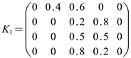 |
| Joint fissures development degree | 0 | 0 | 0.2 | 0.8 | 0 | |
| Rock mass integrity index | 0 | 0 | 0.5 | 0.5 | 0 | |
| Weathering degree of rock mass | 0 | 0 | 0.8 | 0.2 | 0 | |
| permeability coefficient | 0 | 0 | 0 | 0.9 | 0.1 | 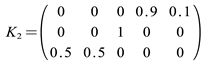 |
| Seawater depth | 0 | 0 | 1 | 0 | 0 | |
| buried depth of tunnel | 0 | 0.5 | 0.5 | 0 | 0 | |
| relative size | 0 | 0 | 0 | 1 | 0 | 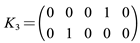 |
| Tunnel spacing | 0 | 1 | 0 | 0 | 0 | |
| drilling and blasting method | 0 | 0 | 1 | 0 | 0 | 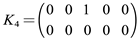 |
| shield method | 0 | 0 | 0 | 0 | 0 | |
| multi centered circle | 0 | 1 | 0 | 0 | 0 | 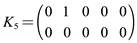 |
| circular | 0 | 0 | 0 | 0 | 0 | |
Disclaimer/Publisher’s Note: The statements, opinions and data contained in all publications are solely those of the individual author(s) and contributor(s) and not of MDPI and/or the editor(s). MDPI and/or the editor(s) disclaim responsibility for any injury to people or property resulting from any ideas, methods, instructions or products referred to in the content. |
© 2023 by the authors. Licensee MDPI, Basel, Switzerland. This article is an open access article distributed under the terms and conditions of the Creative Commons Attribution (CC BY) license (http://creativecommons.org/licenses/by/4.0/).
Copyright: This open access article is published under a Creative Commons CC BY 4.0 license, which permit the free download, distribution, and reuse, provided that the author and preprint are cited in any reuse.


