

Submitted:
02 October 2023
Posted:
09 October 2023
You are already at the latest version
Abstract
Capturing and storing CO2 (CCS) was once regarded as a significant, urgent, and required option for reducing the emissions of CO2 from coal and oil and gas industries and mitigating the serious impacts of CO2 on the atmosphere and the environment. This recognition came about as a result of extensive research conducted in the past. The CCS cycle comes to a close with the last phase of CO2 storage, which is accomplished primarily by the adsorption of CO2 in the ocean and injection of CO2 subsurface reservoir formation, in addition to the formation of limestone by the process of CO2 reactivity with reservoir formation minerals through injectivities. CCS is the last stage in the carbon capture and storage (CCS) cycle and is accomplished chiefly via oceanic and subterranean geological sequestration, as well as mineral carbonation. The injection of supercritical CO2 into geological formations disrupts the sub-surface's existing physical and chemical conditions; changes can occur in the pore fluid pressure, temperature state, chemical reactivity, and stress distribution of the reservoir rock. This paper aims at advancing our current knowledge in CO2 injection and storage systems particularly CO2 storage methods and the challenges encountered during the implementation of each method and analyses on how key uncertainties in CCS can be reduced.
CCS sites are essentially unified systems; yet, given the scientific context, these storage systems are typically split during scientific investigations based on the physics and spatial scales involved. Separating the physics by using the chosen system as a boundary condition is a strategy that works effectively for a wide variety of physical applications. Unfortunately, the separation technique does not accurately capture the behaviour of the larger important system in the case of water and gas flow in porous media. This is due to the complexity of geological subsurface systems, which prevents the approach from being able to effectively capture the behaviour of the larger relevant system. This consequently gives rise to different CCS technology with different applications, costs and social and environmental impacts.
The findings of this study can help improve understanding of selecting a suitable CCS application method and can further improve the efficiency of greenhouse gas emissions and their environmental impact, promoting the process sustainability and helping to tackle some of the most important issues that human being is currently accounting global climate change. Though this technology has already had large-scale development for the last decade, some issues and uncertainties are identified. Special attention was focused on the basic findings achieved in CO2 storage operational projects to date. The study has demonstrated that though a number of CCS technology has been researched and implemented to date, choosing a suitable and acceptable CCS technology is still daunting in terms of its technological application, cost-effectiveness and socio-environmental acceptance.
Keywords:
Aquifer
; Carbon Subsurface storage (CSS)
; CO2 Sequestration
; Environment
; Geological storage
; Carbon Capture and Storage (CCS)
1. Introduction
Previous studies have emphasized Anthropogenic CO2 as well as other greenhouse gas (GHG) emissions that have indeed been recognised as the primary cause of global warming and climate change (MacDowell et al., 2013). The reports published by IEA 2016 and NASA 2017 confirmed that CO2 concentrations in the atmosphere have risen from 280 ppm in the mid-1800s to approximately 404 ppm in 2016, resulting in a nearly 1°C increase in mean earth temperature above the pre-industrial levels. This temperature increase, which occurred between 1901 and 2010, resulted in a 20cm increase in worldwide mean sea level (UK Met Office 2016). It is widely acknowledged that the average global temperature increase from pre-industrial rates must be maintained far below 2°C by 2100 to avoid catastrophic climate change disasters (IPCC special report 2005). As a result, the European Union and the G7 countries have set a goal of reducing GHG emissions by at least 80% from 1990 levels by 2050 (IEA 2009) and (ECF 2010).
Power plants and other energy-intensive sectors are regarded as significant CO2 emitters and are required to reduce their produced CO2 emissions substantially. The high carbon intensity of the power industry (World Nuclear Association) 42%, is due to the significant proportion of coal-fired facilities in the worldwide energy supply. Furthermore, the development of shale gas in North America has resulted in an increase in coal production and exports from the United States. As a result, it resulted in a significant decrease in coal pricing, which in turn resulted in a greater proclivity for coal-based power generation (Hanak et al. 2015). Therefore, de-carbonization of the electricity and manufacturing sectors is critical to meeting emission reduction goals.
CCSI in 2011 provided evidence for Carbon Capture and Storage (CCS) as the most crucial method for decarbonizing the electricity and industrial sectors. It is predicted that CCS alone may contribute almost 20% of the decrease by 2050 and that excluding CCS can result in a 70% increase in the worldwide cost of meeting emission reduction goals (UK DECC 2012). Permanent CO2 sequestration is the US-DOE United States Department of Energy's plan. USGS VSP Vertical Seismic Profile XRD (X-Ray Diffraction) is the final step in the CCS chain and could be implemented using a range of strategies, primarily mineral carbonation, oceanic, and underground geological storage along with saline aquifers, oil and natural gas reservoirs, inaccessible coal seams, and other geological porous media. According to Yamasaki (2003), the critical criteria of a viable CO2 storage option are net CO2 emission reduction, high storage capacity, long-term CO2 isolation (at least several hundred years), acceptable cost and energy penalty, and little environmental effect. However, public acceptance/embracing is another essential element that may have a significant impact on the technology's adoption, Mabon et al. (2013).
Several reviews, including Bachu (2015), and (Bai et al. 2015), have addressed various features of CO2 storage in the past. However, particular areas have yet to be addressed or thoroughly examined. Although CO2 storage is a technically established technique, further deployment is hampered by ambiguity and challenges related to estimating storage capacity, tracking verification and monitoring of CO2 during and after injection, characterising potential injection-induced seismicity, and standardising storage evaluation criteria, and practical, ethical mechanisms. Furthermore, CO2 storage is a dynamic subject, and current success and growth must be examined and addressed as more information becomes available.
Within the framework of CCS, there exist various potential avenues for the sequestration of CO2. These options include underground geological storage, deep ocean storage, and mineral carbonation (IPCC Special Report, 2005). Underground geological storage, in particular, encompasses several subcategories, such as saline aquifers, depleted oil and gas reservoirs, un-mineable coal seams, hydrate storage, and CO2 storage within enhanced geothermal systems (Na J, et al. 2015)
This section offers a thorough examination of each storage approach and afterwards delineates potential avenues for future research that can enhance the existing knowledge.
CCS is widely recognised as a crucial approach for achieving decarbonization in the manufacturing and energy sectors (GCCSL, 2011). According to estimates, the implementation of CCS technology alone has the potential to achieve a reduction of about 20% in emissions by the year 2050. Furthermore, the absence of CCS might result in a significant rise of up to 70% in the overall global cost required to meet emission reduction targets (DECC, 2012). The final stage in the CCS process involves the long-term containment of CO2. This can be accomplished through several methods, such as mineral carbonation, oceanic storage, and underground geological storage. The latter includes storing CO2 in saline aquifers, depleted oil and gas reservoirs, unmineable coal seams, and other geological formations. The primary attributes of a viable CO2 storage solution encompass a net decrease in CO2 emissions, substantial storage capacity, extended isolation of CO2 for a minimum of several centuries, cost-effectiveness and minimal energy penalty, as well as mitigated environmental consequences (Yamasaki, 2003). However, the acceptance and embrace of the technology by the general population is another crucial component that can have a substantial impact on its implementation (Mabon and Shackley, 2013).
Multiple scholarly articles have examined many facets of CO2 storage (Bachu, 2015) as indicated in Appendix A. Nevertheless, certain aspects have not yet been addressed or thoroughly examined. Although CO2 storage has been demonstrated to be a technically viable technology, its widespread implementation is hindered by various uncertainties and challenges. These include difficulties in accurately estimating storage capacity, effectively tracking, verifying, and monitoring CO2 during and after injection, characterising the potential for induced seismic activity resulting from an injection, establishing standardised criteria for evaluating storage sites, and implementing effective ethical mechanisms. Furthermore, the topic of CO2 storage is rapidly advancing, necessitating a comprehensive examination and discourse on recent advancements and developments.
In course of preparing this paper, a comprehensive and critical review has been carried out on the most up-to-date CCS methods and identify their application, limitations and potential future work through research analyses.
2. CO2 Sequestration Methods
According to the IPCC Special Report from 2005, different CO2 sequestration methods that could be used for stored CO2 include deep ocean, geological and mineral carbonation, several subterranean reservoir formations alternatives do exist, including saline aquifers, depleted oil and gas reserves, unreachable coal seams, hydrate storage, and CO2 inside improved geothermal systems, (Bachu et al. 2000), (Han and Winston Ho 2020).
Figure 1 and Appendix A presents a comprehensive review of significant large-scale CSS initiatives that have been implemented globally. In the majority of these operations, CO2 has been sequestered in saline aquifers or utilised for enhanced oil recovery (EOR) purposes. The security of containment is a critical determinant for the success of storage projects. Therefore, it is imperative to consistently enhance the process of selecting and characterising sites, determining technical operation parameters, developing monitoring and verification systems, and conducting quantitative risk assessments. Taking a comprehensive approach to these variables will serve as the foundation for developing suitable technical rules and fostering a favourable public image, thus facilitating the smooth implementation of large-scale CSS operations.
The utilisation of underground geological storage has been widely regarded as the most feasible method for sequestration. Geological storage is considered a more advantageous method of sequestration when compared to carbonation and oceanic storage due to various factors. These factors encompass economic considerations, site accessibility (particularly relevant to ocean and mineral sequestration), as well as concerns related to the security of stored CO2 and the potential negative environmental consequences associated with mineralisation and ocean storage. This section will provide a full discussion of many potential geological storage alternatives, as depicted in Figure 2 below.
2.1. Storage in Subsurface Reservoir Formations
The most workable sequestration option is an underground geological storage system. The security of the CO2 being stored, as well as the detrimental effects on the ecosystem, are some of the key points that set geological storage from CO2 mineralization and marine storage. Figure 1 depicts various possible geological storage systems that are considered to be effective and would need further investigation for better understanding.
Considering that available information in the overwhelming CSS can managed at the vast majority of locations efficiently and safely, there is still a possibility that storage facilities might be put in danger by factors such as generated seismicity if these factors are not well analysed.
2.1.1. Brine Aquifers
Several researchers have acknowledged that storing CO2 in deep salty aquifers represents one of the most successful strategies for reducing CO2 in the atmosphere (Li et al. 2023) (Javaheri et al., 2011), (Yang et al. 2013), (Frerichs et al., 2014), and (Burnol et al. 2015), due to its already available technological and significant possible storage capacity, (Bachu et al. 2000). However, most saline aquifers are presently unsuitable for other synergistic or competing uses (Trémosa et al. 2014) especially in highly populated nations (Procesi et al. 2013; Quattrocchi et al. 2013). The absence of facilities including wells for CO2 injection, surface handling equipment, and transportation pipeline networks makes many salty aquifers less desirable as potential storage reservoir formation alternatives at the moment (Li et al. 2006).
Recently, the topic of discussion has been the potential for CO2 to be stored in salty aquifers (Bachu et al., 2003), (Wei et al. 2022) in combination with EOR storage (Boundary-Dam-Apache). These studies address topics including site description, as well as long-term planning, according to (Bachu 2010) as well as the range of complementary and competing subterranean uses (Procesi et al. 2013).
Because of their vast pore volume and high permeability, aquifer reservoir formations can hold massive amounts of CO2, cutting down on an overall number of CO2 injection wells required and easing pressure dissipation (Shukla et al. 2010). Upon flowing into the storage reservoir formation, supercritical CO2 dislocates brine in the pore spaces and initiates a chain reaction with the formation's minerals (groundwater, gas, and rocks) that lead to either formation of different chemical substances or the breakdown of current minerals (Le Gallo et al. 2002), (Cantucci et al. 2009). Mineral formation and dissolution may alter rock porosity and, as a result, the capacity of the storage reservoir (Wdowin 2013).
Previous studies (Tapia et al. 2018) have shown that supercritical CO2 has a density of approximately 0.6-0.7g/cm3 in saline reservoirs, the low density can influence the uprise movement of CO2 towards the cap-rock because of buoyancy forces due to density variation.
According to previous studies (Armitage et al., 2013), a large aquifer storage basin with a high sealing capacity of the cap-rock is necessary for long-term and stable CO2 storage. Given that cap-rock, a formation at the reservoir's top with low to very low permeability (Fleury et al. 2010) should operate as a seal to prevent CO2 migration from the storage deposit below. With its low permeability, cap-rock is crucial for preventing CO2 from escaping the retention reservoir and minimizing leakage. Another essential element that may result in cap-rock integrity loss and CO2 leakage is the existence of unrecognised fracturing and fault-plane. However, from the review, no previous researcher has investigated further study on the impacts of CO2-brine reactivity on injectivity and the fracturing network and fault plane for CO2 storage, as such, a thorough research study is required to investigate the effect of this reactivity and previous faults on cap-rock stability (Buttinelli et al. 2011).
Figure 3 below depicts the four major trapping processes that may safely handle CO2 storage: a) Structural/stratigraphic; b) Residual; c) Solubility; d) Mineral trapping.
Stratigraphical and/or Structural Trapping: When CO2 is introduced into a geological formation, it may move to the top and get trapped behind an impermeable top seal (Kim et al. 2017) where it can remain as a free phase that cannot go beyond or access the cap-rock pore region except by slow diffusion or fractures as illustrated on Figure 3a above. It’s the most common kind of subsurface trapping system.
CO2 Rock Pores Capturing: Injection of CO2 into aquifer porous rock gives rise to fluid displacement due to differences in density. Figure 3b above shows how the fluid displaced by the CO2 flows, returns, disconnects, and traps the remaining CO2 within pore spaces. It has been observed that the method occurs exclusively when water drainage processes occur during CO2 injection, rather than inside structural and stratigraphic traps, (Bachu et al. 2007).
Solubility trapping: CO2 dissolves in brine through the chemical process of solubility, plummeting the quantity of CO2 gas-phase (Figure 3c). The density of brine is increased by the solubility of CO2 and this may cause gravitational instability, hastening the transition of injected CO2 to CO2-lean brine (Kneafsey et al., 2010).
Trapping due to Mineral: CO2 undergoes chemical interactions with minerals and salty water found around the rock's periphery. Carbonate precipitation occurs as a consequence of these chemical reactivities and has the effect of sequestering CO2 in an inert lesser phase across a specific subsurface geological timeframe, as demonstrated in Figure 3d above (Bachu 1998). It is a more gradual process than the solubility capturing that takes place over a longer geologic period (Gunter et al. 2004), (Sundal et al. 2014).
Although a number of studies have argued that storing CO2 in salty aquifers would be more effective than CO2 is often stored in depleted oil and gas fields, these assessments neglect to take into consideration the expenses connected as a result of the use of storage in saline reservoirs. In many instances, hydrocarbon fields already have production facilities in place, which, with only relatively modest adjustments, may be modified to meet storage operations. These changes can be made in order to accommodate storage activities. In addition, they have been well defined throughout the stages of crude oil exploitation, and they may employ CO2 for storage as well as EOR. As a consequence, it is possible that storing CO2 in hydrocarbon formations is better than storing it in saltwater aquifers.
2.1.2. Drained Hydrocarbon Reservoir Formations
The sequestration of CO2 in depleted oil and gas reservoirs is widely recognised as one of the most efficient techniques of CO2 storage. Among these advantages are the following: a) Drained hydrocarbon reservoirs have been the subject of substantial research both before and during the hydrocarbon exploring period, including research about their storage capacity; b) Both onshore and offshore infrastructural facilities, existing infrastructure, including CO2 injection wells and transportation, may be used with little modification for the storage process (Sigman et al. 2021); c) If this was not the case, CO2 gas injection to enhance oil recovery would have been less attractive and ends many years ago. Suitable hydrocarbon field data as an analogue may be utilise in illustrating the efficacy of cap-rock across geologic timeframe to strengthen oil and gas reservoirs (Heinemann et al. 2012).
Reservoir rocks and brine properties are similar and commonly found in both hydrocarbon reservoirs and deep aquifer storage systems (Li et al., 2014). Oil and gas reservoirs, on the other hand, may be considered for EOR, making them more economically advantageous than saline aquifers, (Zangeneh et al. 2013) and (Gao et al. 2016). Because the worldwide average recovery factor from a typical oilfield is about 40%, (BGS, 2017), usually, many barrels of oil are still in the hydrocarbon reservoirs. It’s the primary motivation for the global deployment of EOR. However, technological deployment difficulties remain challenging, although these issues may have been foreseen and handled throughout the exploration and production phase of a field, they have just recently come to light.
Gas injection is the most frequently utilised among the current EOR alternatives such as gas, thermal, chemical, and plasma-pulse injection techniques. Miscible gases (CO2, nitrogen, and natural gas) are injected into the reservoir using the gas injection process to decrease the interfacial tension between oil and water and increase oil displacement efficiency while preserving reservoir pressure. CO2 injection seems to be the optimal choice because it may reduce oil viscosity and is less expensive than liquefied natural gas (Jaramillo et al. 2008). More CO2 for improved oil recovery is anticipated to be accessible from vital gathering point sources with the introduction of CCS technology (IPCC Special Report 2005). It has been claimed, for example, that the use of CO2 for EOR has resulted in an increased output of about 260,000bopd in the U.S.A (GCCSI 2017).
The International Energy Agency (IEA) 2015 set out the following as the primary criteria for the implementation of CO2 oil recovery support (EOR) projects:
Additional site characterization involves investigating potential leakage risks, such as the condition of the cap rock and any abandoned wells with integrity problems.
Additional evaluations of surface processing plants' fugitive and discharging emissions
Leakage rates may be estimated from specific locations and the normality of the reservoir's behaviour can be determined by increased monitoring and field surveillance.
In addition to the criteria mentioned above, governments must address legal problems and enact laws to cover storage facility operations. These issues arise because CO2-EOR and CO2 permanent storage fall under two distinct regulatory umbrellas, the former focuses on resource recovery, whereas the latter is concerned with waste management Marston (2013). Legal issues might arise, for instance, regarding the proper decontamination of oil left in situ after production ceases, if hydrocarbon recovery is prioritised. Such a scenario may be jurisdiction-specific and especially significant when onshore mineral and storage rights are owned privately.
One of the critical variables that must be rigorously defined before a CO2-EOR project is initiated involves the kind and number of contaminants in CO2 streams. Depending on the CO2 source and the accompanying collecting procedures, a variety of contaminants might be contained as part of the CO2 injection fluid. (Porter et al. 2015). The permissible impurities and concentrations are determined by a mix of transit, storage, and economic factors. CO2 streams must meet a minimum purity standard of roughly 90%vol (Jarrell et al. 2002). In the case of CO2, increasing impurity levels may cause the phase boundaries to move to even higher pressures, which demonstrates the requirement for higher injection pressures to keep the injected CO2 in a higher concentration. It has also been established that non-condensable contaminants lower CO2 storage capacity by a factor that is larger as compared to the mole percentage of contaminants present in the CO2 injection system (IEAGHG 2011).
The most typical issue connected to contaminants is corrosion. Due to the corrosive effects that impurities (such as SO2, NO2, CO, H2S, and Cl) may have on transportation and injection systems, it is essential to limit the quantity of contaminants on a scenario rationale. Additionally, it is essential to develop feasible mitigation solutions for potential problems, (Porter et al. 2015). It is important to note that even though certain impurities such as CO, H2S, and CH4 have a naturally occurring propensity to be combustible, safety considerations for combustibility are not typically factored into the evaluation of safety measures. This is because it is highly unlikely that the CO2 injection stream will be combustible due to the low quantities of the impurities in question. Another issue that may influence the effectiveness of the CO2-EOR process is an excessive concentration of O2 in CO2 streams. The presence of O2 in the reservoir may stimulate microbial activity, (Porter et al. 2015), which can ultimately lead to operational problems such as injection obstruction, oil deterioration and oil souring.
The previous studies (Igunnu et al., 2014) have connected environmental problems of EOR with volumes of water production that may include radioactive compounds and dangerous heavy metallic substances. Failure to implement an appropriate waste management and disposal strategy implemented, these chemicals may pollute drinkable water sources. Although restrictions exist, governments must ensure that operators follow current laws when brine re-injection for recovery is permitted. For example, White (2009) provided evidence to show that the Weyburn-Midale CO2 storage project in Canada is an example of how collected in the Weyburn oilfield, CO2 might be used for EOR and retention. Not only does this procedure recover a significant amount of previously unrecovered oil, but it also increases the oilfield's useful lifespan by 20–25 years, Thomas (2008). According to (Zaluski et al. 2016) ; (Verdon 2016) long-term surveillance, generated seismicity evaluation of CO2's impact on the reservoir and the fluids' mutual effect, oil and minerals have been the primary focuses of CO2-EOR research (Hutcheon et al. 2016). The Weyburn case history inspired (Cantucci et al. 2009) to study the geochemical equilibrium between brine and oil and develop a biogeochemical model for CO2 storage in underground reservoirs. A hundred years into the future, they predicted precipitation and disintegration processes based on research into reservoir formation during CO2 injection. During the first year of the simulation, they discovered that the two most significant chemical processes taking place in the reservoir were those involving CO2 and the dissolution of carbonate. Furthermore, the development of chemical characteristics over time indicated that CO2 might be securely stored via mineral and solubility trapping.
Perera (2016) acknowledges that though the CO2-EOR method has substantially improved oil recoveries, further improvement is needed using the following strategies: a) Using numerical evidence, (Tenasaka 2011) proved that this was possible within the normal range of CO2 injection. In the San Joaquin basin, scientists injected around 2.0HCPV (hydrocarbon pore volume) of CO2 to prove that there was a greater possibility to extract more oil, almost 67% of the originally present oil (OOIP) was recovered. In addition, (Tenasaka 2011) demonstrated that there was a greater recovery of oil from his numerical methodology; b) Using a better and innovative CO2 flooding design and well management can positively influence more oil recovery from the reservoir; c) Increasing the mobility-ratio by raising water’s viscosity (Thomas 2008). Minimising miscibility pressure using miscibility-enhancing agents, Kuuskraa (2008).
2.1.3. In-accessible Coal Seams
An additional option for sequestering human-caused CO2 is the use of inaccessible coal seams. Since cleats are present inside the coal matrix, the system is somewhat permeable. In addition, the matrix of coal is full of tiny holes (micropores) that may take in a lot of air. Coal has a greater affinity for CO2 in the gas phase than methane, and this is the basis for the CO2 trapping process. According to (Shukla 2010), this means that the methane output could be increased while the CO2 was permanently stored. Thus, large amounts of CO2 may be stored while commercial unconventional shale methane (CBM) processes are made more productive and profitable (Krooss et al. 2002), (Gilliland et al., 2013). It should be underlined that although CO2 increases CBM synthesis, the overall quantity of methane generated is not always higher than without the addition of CO2. The International Energy Agency Working Group on Greenhouse Gases (IEAGHG 2009) provided an overview of the essential technical parameters needed for the effective implementation of enhanced coal seam production, which include: a) The homogeneity Reservoir; b) Threshold of fractures and fault planes; c) Upper depth limit; d) Coal geomorphology; e) Permeability adequacy.
Two experimental locations, the Alberta Carbon Trunk Line (ACTL) in Canada with the San Juan Basin pilot in the United States, have reportedly used the ECBM approach, the conclusion of the evaluations for the Alberta project (Krooss 2002): a) Even in constrained reservoirs, continuous CO2 injection is feasible; b) Injection may be performed notwithstanding a decrease in injectivity; c) Expected Significantly Enhanced CBM Production; d) The injected carbon dioxide stays in the reservoir, boosting sweep efficiency, (Lakeman 2016).
Key findings from the San Juan Basin pilot study revealed that methane recovery exceeded the predicted ultimate primary production. Second, the pilot project was not cost-effective because of the price of gas at the time it launched. However, if the price of gas continues to climb in the years to come, the pilot project may end up being lucrative; thirdly, because fuel prices were high when the project was first implemented, the trial project was not profitable. An additional pilot study of a Coal field is being done in the Appalachian Basin, with a focus on a variety of surveillance and verification techniques, and accounting (MVA) methods are being utilised to understand better storage complexity, (Gilliland et al. 2012). Furthermore, the possible ECBM implementation, as well as the significant variations in output across nearby wells with the same stratigraphic, has been studied in the beginning. However, further research is needed to characterise and portray such disparities adequately.
While CO2 EOR has been used successfully for years in the upstream oil and gas sector, the utilisation of CO2 during ECBM is still limited in its recognition. There are still many unknowns when it comes to ECBM recovery, however, the current understanding of how the CO2 EOR process works could help alleviate some of those worries. For example, the creation of technically recoverable shale in ECBM could need a look at already-existing technology from the oil industry that might be converted with very little work. Existing well materials may be utilised as a baseline for good integrity in ECBM production following suitable changes. Furthermore, field and reservoir management techniques processes, such as risk monitoring and evaluation may be modified from those already in place and used at any point in the lifetime of a project.
2.1.4. Subsurface Basalt Formations
There exists a considerable body of literature on subsurface basalt deposits within central igneous provinces, and many researchers (McGrail et al. 2006), (Pollyea et al. 2014) and (Matter et al. 2016) have suggested subsurface basalt deposits as a possible CO2 storage solution. Basaltic rocks make up around 8% of the continents and a large portion of the ocean bottom. As a result, basaltic rocks have a massive theoretical CO2 storage capacity (Anthonsen et al. 2014). One of the most important advantages of such rocks' potential to store CO2 is that their physical and chemical characteristics, as well as the amount of divalent metal ions they contain, may fix CO2 during past geological periods (Van Pham et al., 2012). Permeability and porosity of Basalt flows, on the other hand, are very variable and often consist of an interior low-permeability region surrounded by periphery regions with high permeability. That said, the rubbly zones between separate flows are the most critical portions of a basalt sequence for CO2 storage.
Complimentary CO2 injected into subsurface basalts (the CarbFix pilot scheme, Iceland) may replace water in the rock's pore spaces and cracks (Matter et al., 2011). The decrease in water content may impede basalt carbonation and hydration. Therefore, it may be possible to inject CO2 and the right amount of water into the same reservoir based on the following points: a) Because it offers sufficient depth, denser CO2 liquid may sink, which delays the release of CO2 back into the atmosphere; b) It makes it possible to form stable carbonates in a shorter amount of time than would normally be required by geologic processes; c) It prevents acidic basement fluids from rising via an impervious sediment layer; d) It can be converted into a stable hydrate; e) It is essential to remember that a small quantity of CO2 leaking does not inevitably damage the sea bottom ecosystems.
Because of the anticipated development of dolomitic carbonate minerals, with the possibility of CO2 being trapped in basalts for thousands of years, analysing changes in rock volume and the chance of fracture self-healing are key issues to consider. Quantitative research on such issues has been conducted (Van Pham et al., 2012). These researchers found out that at 40 degrees Celsius, oxide consumed a significant amount of calcium, limiting its use to the creation of siderite and ferromagnesian carbonates. Magnesite formed with ankerite and siderite at temperatures between 60 and 100 degrees Celsius. In addition, they found that the carbonation and hydration processes both increased solid volume and inhibited pore access, decreasing the maximum quantity of CO2 stored.
In addition to studying the mineral assemblages present in basalt, researchers have looked at the mechanisms of mineral carbonation in serpentinites, intending to acquire a more thorough comprehension of the fundamentals of CO2 storage for the future utilising basic magnesium silicates. In serpentinites, rocks that are both plentiful and thermodynamically suitable for the production of magnesium carbonates, CO2 combines with magnesium silicates to produce magnesium carbonates (Seifritz 1990). (Andreani et al. 2009) conducted an analysis of the carbonation process using flow parameters that were optimised. They found out that low-flow or low-diffusion regions are the only ones where porosity and permeability decrease. In contrast, higher flow rates contribute to armouring of mineral surfaces associated with the initial disintegration.
And further reason for alarm has been the occurrence of fractures in the basalt formations' protective cap-rock. Due to the possibility of leakage via the fissures, basalts are not likely to be suitable for CO2 storage. However, CO2 seeping via fissures has the potential to mineralize and be trapped inside the formation, delaying its escape to the surface (IEAGHG, 2011). As such, further research is required to characterise the kinetics of CO2-basalt interactions.
Alternate storage alternatives, including serpentinite and basaltic reservoir formations, could be necessary; knowledge improvement is required to identify possible uncertainties and investigate mitigation techniques. To do so, it may be necessary to apply computational techniques and to research the impact of carbon dioxide and rock contact on the ease or difficulty of migration, as well as to clarify CO2 migration in the presence of likely fault plane, fractures.
2.1.5. CO2 Sequestration in Hydrate Deep Formations
Previous studies (Anon n.d.) have shown that subsurface CO2 storage systems as hydrates is another potential, modern strategy that uses a lattice of water molecules to capture CO2 molecules. When water and the right level of pressure and temperature are present, CO2 hydrate may form rapidly (Circone et al., 2003). Furthermore, its rapid formation kinetics may allow for some self-sealing in the rare crack development in the hydrate top layer formation. The development of CO2 hydrate might have applications in both underground geology and the storage of CO2 in the ocean. Because the formation of hydrate turns out to be very stable at higher pressure and low temperature of about 10°C (Rochelle et al. 2009) they can only be used in certain situations, such as shallower sediments under cold oceans bed and under extensive areas of icy hydrate formation, where it's possible that there is a lack of sufficient space for a CO2 collecting plant.
The process of CO2 hydrate storage mechanism involves buoyancy and drives the migration of liquid CO2, which is capped by a developing impermeable CO2 hydrate cap, (Figure 4 below). The CO2 hydrate equilibrium zone is lowered by injecting liquid carbon dioxide into deep water or sub-permafrost sediments, (Rochelle et al. 2009). As more liquid CO2 moves into the colder hydrate stable zone, a layer of impenetrable CO2-hydrates builds inside the pore holes of the sedimentary reservoir rock. The US Department of Energy (DOE) on the other hand proposed a CO2-EGR-based hydrate storage technology (enhanced gas recovery). CO2 is injected into sediments that contain methane hydrates, releasing the methane from the hydrates and forming CO2 hydrates in its place (Burnol et al. 2015). Because CO2-EGR is still a novel idea, research into its effectiveness has been limited so far. According to Oldenburg (2003), one of the primary issues is the use of Methane which might in turn react with the injected CO2 in an enhanced gas cycle, resulting in the gas resources being depleted.
Presently, the technology required to store CO2 in hydrates is not very advanced with most researchers (Jemai et al. 2014), (Talaghat et al. 2009) focusing on theoretical modelling and lab-scale experiments Ghavipour et al. 2013), (Ruffine et al. 2010) and (Rehder et al. 2009). For this reason, there are still a number of challenges to be solved, especially with CO2-EGR. However, local temperature and pressure fluctuations caused by drilling through hydrate-bearing sediments may destabilise the hydrate formation in its entirety (Khabibullin et al., 2011). How the CO2-CH4 hydrate exchange mechanism affects methane production, and how hydrate cap development may be shown as the major outstanding problems that need to be solved to improve the evaluation of hydrate storage viability.
2.1.6. Enhanced Geothermal Systems Based on CO2
Previous studies (Garapati et al. 2015), (Pruess 2006), (Zhang and Song 2013) have emphasized that dense-phase CO2, like water, has thermal characteristics that allow it to transfer large quantities of heat. However, it has better physical characteristics, such as substantially lower viscosity, more excellent compressibility, and expansibility. As a result, CO2 may be utilised in the process of geothermal energy by extracting heat from the ground. CO2 can efficiently reach the rock mass due to its low viscosity and may be considered a medium for enhanced geothermal systems' operating fluid (Pruess 2006). Enhanced geothermal systems that use water as the heat transmission fluid suffers from the drawback of fluid loss. The inability to provide adequate water supplies is associated with financial difficulties because of the value placed on this resource. On the other hand, if upgraded geothermal systems (EGS) were to lose their reliance on CO2, this would make underground geological storage of CO2 possible, which might have further benefits.
It is essential for the effectiveness of CO2-EGS storage that the rock mass loaded with CO2 be separated from the surrounding rock mass, which is filled with water. These conditions are maintained in large part due to the formation of crystals of carbonate minerals at the interface between the CO2-heavy centre of EGS with the brine-rich outside. Only countries having subsurface resources at economically feasible depths where the temperature is high enough would be able to use this technology. Additionally, synergistic use of the subsurface may be more complicated and need more collaboration in heavily populated nations.
The technique is still in its early stages of technology readiness (TRL), with most research so far focused on theoretical modelling (Plaksina et al., 2016) and small-scale laboratory experiments. The main challenge to this method's development is the lack of clarity about the efficiency of closing off the area surrounding the CO2 source. To top it all off, nothing is known about the interactions between CO2 and rocks at high temperatures. Understanding how CO2 affects dissolution and precipitation, and how that affects changes in fracture permeability and EGS functioning, requires further study.
2.2. Carbonation of Mineral
Seifritz in 1990 was the first person to suggest the idea of CO2 carbonation happening in the mineral as an alternative CO2 sequestration method. The collected CO2 is sequestered using this technique via the mineralisation process; in the presence of oxides or hydroxides of alkaline metals found in minerals, Carbonates are produced by the reaction of CO2.
Incorporation of CO2 into minerals may be accomplished in two ways: both in and out of place. The in-place technique includes injecting CO2 into a geologic formation to produce carbonates. Meanwhile, the out-of-place process is carried out above the surface in a factory utilising rock that has been excavated earlier or rock that is indigenous to the area (Assima et al. 2014). In situ, mineral carbonation is often discussed in high-magnesium, high-iron, and high-calcium silicate rocks like basalts and ophiolites (Ekpo Johnson et al. 2023). The in-situ mineral carbonation technique has significant benefits since it does not need substantial mining and just a few boreholes to complete the process. However, there may be significant unknowns, such as the absence of geological characteristics or the lack of knowledge on the possible cap-rock or seal.
CO2(g) + MgO(s) → MgCO3(s), ΔH ≈ -118KJ/mol
CO2(g) + CaO(s) → CaCO3(s), ΔH ≈ -179KJ/mol
Also, geochemical processes may decrease reactivity, porosity, and permeability, lining the resultant flow channels. There are both direct and indirect techniques that could be used to carbonate minerals outside of their natural environments. The direct gas-based technique comprises the interaction of gaseous CO2 with minerals to form carbonates, as previously shown (Bobicki et al. 2012) and (Lim et al. 2010). Gas-solid carbonation normally occurs at temperatures below 65°C, with the rate of chemical reaction and the amount of space available in rocks being the key limiting variables (Calabrò et al. 2008). The direct aqueous-based process consists of a single stage, which entails CO2 interacting with mineral deposits in the presence of water. This step takes place in the presence of water (Bobicki et al. 2012). Direct mineral carbonation has significant challenges in commercial deployment and development due to minerals and carbon dioxide being dissolved and forming a product layer dispersion (Olajire 2013); (Bobicki et al. 2012)). When looking at the feasibility of long-term mineral carbonation that allows for the underground sequestration of carbon dioxide, Matter and Kelemen in 2009 turned to natural analogues. According to their findings, sedimentary rocks that have magnesium and calcium elements in quite high concentrations tend to have a high rate of mineralization. Their results reveal that carbonate mineral precipitation may fill gaps already present, but that the tension caused by fast precipitation may also cause fracture and an increase in pore volume. The mining industry has a snowball impact on the environment because some mineral deposits that are rich in calcium and magnesium may also include asbestiform components as well as other pollutants that are harmful to human health (IPCC Special Report 2005).
Two of the most common alkali and alkaline-earth metal oxides, magnesium oxide (MgO) and calcium oxide (CaO), don't develop as binary oxides in free existence. Magnesium oxide has the chemical formula MgO, while calcium oxide has the chemical formula CaO. Compounds based on silicon dioxide, such as serpentine, are typical examples of this kind of assemblage. (Cipolli et al. 2004) and (Bruni et al. 2002) conducted studies on the effects of carbon dioxide on serpentine that had been retrieved from the spring waters of Genova. Serpentinization modifies the complex interaction of ultramafic rocks with meteoric fluids, according to the results of a geochemical study of serpentinite-derived high-pH fluids and reaction-path simulation for aquifer-scale sequestration (Cipolli et al. 2004). MgHCO3 waters are formed when CO2 reacts with the rock, whereas Na-HCO3 and Ca-OH type fluids are synthesised by further interactions with the host rock in a strongly lowering closed loop. Prior to employing reaction path modelling to simulate the process of injecting CO2 at elevated pressure into aquifer formation, the findings suggested that serpentinites might be exploited for CO2 sequestration because of their ability to create carbonate minerals. It should be emphasised that this method was only successful in reducing aquifer porosity under the circumstances of a closed system. This indicates that such consequences have to be examined thoroughly in both field and laboratory research.
Bruni and team in 2002 conducted research on the spring waters of the Genova area employing irreversible water-rock mass transfer. As a result of their investigation, they found some non-aligned Mg-HCO3 fluids with several higher-pH Ca-OH fluids connected with serpentinites. They investigated if CO2 sequestration is possible in the near and far future by dissolving serpentinite and then precipitating calcite. This was done in order to find out how effective this method might be. They determined that the interaction of these meteoric waters results in a gradual evolution in the chemistry of the aqueous phase. This development starts with magnesium-rich, low-salinity SO4Cl facies and then moves on to intermediates facies made up of more developed Ca-OH and Mg-HCO3 compounds. In order to arrive at this result, scientists examined dissolved N2 and Ar in addition to water's stable isotopes. Higher alkalinity of Calcium Oxide solvent can capture CO2 and transform it into deposits of Calcite formation or solute, this methodology might be used to sequester anthropogenic CO2.
The implementation of a commercial process necessitates the extraction, pulverisation, and grinding of mineral-rich ores, as well as their transportation to a processing facility that receives a concentrated stream of CO2 from a capture plant Figure 5. The energy consumption associated with the carbonation process is estimated to account for around 30 to 50% of the total output of the capture plant. When taking into account the supplementary energy demands associated with the capture of CO2, it can be observed that a CCS system employing mineral carbonation necessitates an energy input per kilowatt-hour that is 60 to 180% higher compared to an electrical plant without capture or mineral carbonation, serving as a reference. The energy demands associated with this technology significantly increase the cost per metric tonne of CO2 that is mitigated. The most exemplary case examined thus far pertains to the wet carbonation process of naturally occurring silicate olivine. The projected cost of this procedure is roughly 50-100 US$/tCO2 net mineralized, accounting for CO2 capture and transportation expenses, while also considering the supplementary energy demands.
The mineral carbonation process necessitates the extraction of about 1.6 to 3.7 tonnes of silicates per tonne of CO2, and results in the disposal of 2.6 to 4.7 tonnes of materials per tonne of CO2 stored as carbonates. Consequently, the proposed endeavour would constitute a substantial undertaking, with an environmental footprint akin to that of existing extensive surface mining operations. Serpentine is frequently found to contain chrysotile, which is a naturally occurring variant of asbestos.
The existence of this phenomenon necessitates the implementation of monitoring and mitigation strategies similar to those utilised in the mining sector. In contrast, the by-products of mineral carbonation do not contain chrysotile, as it is the most reactive constituent of the rock and hence undergoes conversion to carbonates at the earliest stage.
2.2.1. Limitation and Future Work
There are several unresolved concerns that must be addressed before any assessments of the storage capacity of mineral carbonation can be provided. The concerns encompass evaluations of the technological feasibility and associated energy demands on a significant scale, as well as the proportion of silicate deposits that may be viably and economically utilised for CO2 storage. The potential of mining, waste disposal, and product storage may be limited due to their environmental impact. The current feasibility of utilising mineral carbonation remains uncertain due to the lack of knowledge regarding the potential quantity of exploitable silicate reserves and the presence of environmental concerns, as previously mentioned.
Another crucial inquiry is to the potential of industrial utilisation of CO2 to yield a net decrease in CO2 emissions on a comprehensive scale, through the substitution of alternative industrial processes or products. Accurate evaluation of the CO2 utilisation processes necessitates the consideration of appropriate system boundaries for energy and material balances, as well as the execution of a comprehensive life-cycle study pertaining to the intended utilisation of CO2. The existing body of literature pertaining to this subject is constrained in scope, although it reveals the challenges associated with accurately quantifying specific data. Moreover, it suggests that in numerous instances, the utilisation of industrial practices may result in an overall rise in emissions rather than a net decrease. Based on the limited amount of CO2 kept, the modest quantities utilised, and the potential for substitution resulting in elevated CO2 emissions, it may be deduced that the impact of industrial applications of captured CO2 on mitigating climate change is anticipated to be minimal. Currently, there has been limited effort in evaluating and quantifying the aforementioned external costs. The examination of CCS is conducted within the framework of exploring various strategies for achieving worldwide reductions in greenhouse gas emissions.
Likewise, mineral carbonation might cause issues for both humans and the environment. Mineral carbonation processes have the potential to change the topography of an area in two different ways: via large-scale mining activities and, later on, through the disposal of reacted minerals. In addition, asbestiform phases and other potentially harmful pollutants may be present in some calcium and magnesium-rich mineral formations (IPCC Special Report 2005). Accordingly, future research should concentrate on a) The potential for less terrain change; b) Mineral carbonation in terms of mineral and CO2 dissolution; c) Material stratum diffusion; and d) Managing mineral impurities throughout the sequestration process.
2.3. CO2 Sequestration on Ocean Floor
Intentionally injecting CO2 into the deep ocean floor is another option for anthropogenic CO2 sequestration (IPCC,2018). The oceans cover around 70% of the planet. In the industrial era, they sucked up over a third of all man-made CO2 emissions from the atmosphere and had an average depth of 3.8 km (Adams et al., 2008) and (Tanhua et al. 2013). Mathematical simulations have indicated that injected CO2 may linger in the water for hundreds of years. This cold (1°C) and profound (4 to 5km) water flows slowly and may stay isolated from the atmosphere for millennia.
There are two potential methods for ocean storage: the injection and dissolution of CO2 into the water column, typically below 1,000 metres, using a fixed pipeline or a floating ship; or the deposition of CO2 onto the sea floor at depths below 3,000 metres, using a fixed pipeline or an offshore platform. In the latter method, CO2, being denser than water, is expected to form a concentrated "lake" that would delay its dissolution into the surrounding environment (Figure 6 below). The investigation of ocean storage and its ecological consequences is currently in the research phase.
Direct CO2 dissolution into seawater is the principal technique that could be used in ocean storage. The first involves releasing CO2 directly into the ocean floor, where it will form droplet plumes that will rise into the air. As an alternate method, liquid CO2 is injected into a column, where it has the potential to interact with saltwater at a pace that is under control, therefore producing hydrate (Adams et al. 2008). Since there is a potential for localised acidification of water from the sea in the vicinity of CO2 injection location, the storage of CO2 on the ocean floor is viewed with scepticism by a number of experts. This would have a deleterious effect on the benthic organisms. This is according to a series of recent studies published by Jacobson in 2009 and (Hofmann et al., 2010). Furthermore, it is unclear if international laws will permit CO2 storage in the ocean as a development project. The London Convention for the Protection of the Marine Environment from Pollution by Dumping of Wastes and Other Matter into the Sea signed in 1996 put an end to the practice of discharging wastes from industrial processes into the ocean (Anon 2012a, Anon 2012b). Therefore, it is prohibited to dump CO2 into the ocean if it is considered industrial waste. Although CO2 was added to the "reverse list" in the London Protocol modification that allowed for the storage of CO2 beneath the seabed in 2006, there is still no agreement on whether or not CO2 should be classified as industrial waste. “CO2 may only be stored in compliance with an authorisation or permit given by the Party's competent authority," as stated in the North-East Atlantic Convention with the Interest of Preserving the Quality of the Marine Environment (Anon 2017), (ZeroCO2 2015). Therefore, it is necessary to evaluate the ambiguity surrounding ocean sequestration and its effects on the ecosystem and to provide solutions to possible problems that may arise.
Oceanic sequestration efficiency may be evaluated based on a number of criteria, the most important of which are injection depth, residence time, and CO2 concentration allocation. (Xu et al. 1999) constructed a regional ocean general circulation model that assumed there was no air-to-sea CO2 exchange and investigated the prospect for CO2 sequestration in the North Pacific by using a wide range of sub-grid mesoscale mixing parameters. According to their findings, storage depth is a crucial factor in sequestering CO2 and limiting its emissions back into the atmosphere. It was discovered that a depth of injection of more than 1,000 metres is necessary to slowly release CO2 into the water over very few 100 years.
Following fifty years of constant injection of CO2, more than ten percent of the dissolved CO2 would be released back into the environment. This leakage should be considered as a major concern. Adcroft et al. in 2004 used an ocean circulation model to assess the storage efficiency of impulse injections based on mean residence time. CO2 sequestration was more successful in the North Atlantic over hundreds of years, whereas it was more successful in the Pacific basin over shorter periods. Although the magnitudes that were tested were low and that the impact of air-sea CO2 circulation was ignored, the relevance of this effect over large borders is still a concern and calls for more research.
In order to assess the efficacy of a potential sequestration location, the variation in CO2 concentration after injection might be considered. A place where CO2 is adequately diluted while having little environmental impact is preferable. However, by simulating CO2 injection into a number of models of the ocean's main circulation at several sites around Japan, the spatial variability of CO2 content concerning injection rate and eddy activity distribution has been studied (Masuda et al., 2008) These researchers used an ocean general circulation model to perform their research. Specifically, the data indicated that the highest CO2 concentration may vary by a factor of 10 across places, where the principal driver of this variation is the regionalization of turbulent events. Additionally, it has been established that keeping injection rates below 20Mt/a would have little long-term impact on biota.
2.3.1. Limitation and Future Work
In order to advance the discussions surrounding the evaluation of oceanic sequestration, previous study has shown that a number of improvements and unknowns need to be investigated and resolved in future studies. One way to boost ocean storage efficiency is by updating the present numerical model to account for CO2 exchange between the atmosphere and the ocean, and second, by reducing the number of assumptions underlying the model, further investigating the determination of storage efficiency.
The advancement of ocean CSS can be facilitated by addressing many significant gaps in knowledge and understanding, some of these gaps thus include: a) Further engineering and advancement of technology for operating in the deep sea, as well as the development of various equipment such as pipes, nozzles, and diffusers, that can be efficiently utilised in deep-sea environments while ensuring minimal costs for operation and maintenance; b) Biological and ecological factors – Investigations pertaining to the impact of increased CO2 levels on biological systems inside the deep sea, encompassing investigations of greater duration and larger size than those previously conducted; c) Research centres – these are establishments dedicated to conducting scientific research and developing technologies related to ocean storage. They provide a platform for assessing the effectiveness and impacts of various ocean storage concepts, such as the release of CO2 from a fixed pipe or ship, as well as carbonate-neutralization approaches. These assessments are carried out in situ, on a small scale, and an ongoing basis; d) Finally, the future focus should be on the advancement of methodologies and sensor technologies to detect CO2 plumes, as well as understanding their ecological and geochemical impacts.
3. Discussion and Conclusions
This paper provides a comprehensive review of the current advancements in CO2 sequestration with special interest in geological CO2 storage. This highlights significant steps that have been covered so far, as well as obstacles that still need to be addressed for geological subsurface CO2 sequestration, and approaches adopted in calculating CO2 storage capacity.
Even though CO2 sequestration by storage in the ocean and storage through the process of carbonation has been established, CSS remains the most viable option practical alternative because of financial concerns, vast geographical dispersal, and environmental difficulties. This is the case because it has been proven that CO2 can be sequestered.
Mineral CO2 sequestration on the other hand remains a more protracted alternative in comparison to other potential carbon sequestration methods. The current state of technological progress restricts the short-term sequestration potential. In addition, the present costs associated with its sequestration are somewhat excessive when compared to alternative sequestration methods, taking into account the projected prices of CO2 in the near future. Feasibility may be limited to specific uses that offer an extra benefit, such as the practical utilisation of the carbonated product. Mineral CO2 sequestration has the potential to evolve into a viable technology for employment, forming an integral component of a diverse range of CO2-reducing technologies. It is crucial to use each technology in its most suitable context within a comprehensive portfolio. The field of mineral CO2 sequestration is a relatively recent area of study, and significant advancements have been achieved in improving the pace at which carbonation occurs. The aforementioned observation, in conjunction with the enduring nature of CO2 sequestration and its substantial potential for sequestration, justifies the need for additional investigation into mineral CO2 sequestration.
Acknowledgements
This research did not receive any specific grant from funding agencies in the public, commercial, or not-for-profit sectors. This work is an outcome of research work in the Chemical Engineering Program, School of Engineering, Faculty of Engineering and Digital Technologies, University of Bradford, in Carbon Capture and Utilisation.
Conflicts of Interest
Authors declare that they do not have any conflict of interest with anyone regarding this article.
Abbreviations
| ACTL | Alberta Carbon Trunk Line |
| CBM | Coal Bed Methane |
| CCS | Carbon Capture and Storage |
| CO2CRC | The Cooperative Research Centre for Greenhouse Gas Technologies |
| DOE | Department of Energy |
| ECBM | Enhanced Coal Bed Methane recovery |
| EGS | Enhanced Geothermal System |
| EOR | Enhanced Oil Recovery |
| GHG | Greenhouse Gas |
| HCPV | Hydrocarbon Pore Volume |
| IPCC | Intergovernmental Panel on Climate Change |
| LNG | Liquefied Natural Gas |
| MIT | Massachusetts Institute of Technology |
| MVA | Monitoring, Verification and Accounting |
| OGIP | Original Gas in Place |
| OOIP | Original Oil in Place |
| TRL | Technology Readiness Level |
| UKCCSRC | UK Carbon Capture and Storage Research Centre |
| US-DOE | United States Department of Energy |
| USGS | United States Geological Survey |
| VSP | Vertical Seismic Profile |
| XRD | X-Ray Diffraction |
Appendix A. Worldwide CCS initiatives encompassing large-scale commercial projects that have been previously operational and pilot development operations (MIT, 2015; Shukla et al. 2010; Global CCS Institute - CO2RE)

| Facility Name | Facility Category | Facility Status | Country | Operational | Facility Industry |
|---|---|---|---|---|---|
| In Salah CO2 Storage | Commercial CCS Facility | Completed | Algeria | 2004 | Natural Gas Processing |
| Bridgeport Energy Moonie CCUS project | Commercial CCS Facility | Advanced Development | Australia | 2023 | CO2 Transport and Storage |
| Burrup CCS Hub | Commercial CCS Facility | Early Development | Australia | CO2 Transport and Storage | |
| Callide Oxyfuel Project | Pilot and Demonstration CCS Facility | Completed | Australia | 2012 | Power Generation |
| CarbonNet | Commercial CCS Facility | Advanced Development | Australia | CO2 Transport and Storage | |
| Cliff Head CCS Project (Mid West Clean Energy Project) | Commercial CCS Facility | Advanced Development | Australia | 2025 | CO2 Transport and Storage |
| CO2CRC Otway | Pilot and Demonstration CCS Facility | Operational | Australia | 2008 | Natural Gas Processing |
| CTSCo Surat Basin CCS Project | Pilot and Demonstration CCS Facility | Advanced Development | Australia | 2023 | Power Generation |
| Gorgon Carbon Dioxide Injection | Commercial CCS Facility | Operational | Australia | 2019 | Natural Gas Processing |
| Hazelwood Carbon Capture and Mineral Sequestration Pilot Plant | Pilot and Demonstration CCS Facility | Completed | Australia | 2009 | Power Generation |
| Hydrogen Energy Supply Chain (HESC) project | Commercial CCS Facility | Advanced Development | Australia | Hydrogen Production | |
| Hydrogen Energy Supply Chain (HESC) project | Pilot and Demonstration CCS Facility | Completed | Australia | 2028 | Hydrogen Production |
| INPEX CCS Project Darwin | Commercial CCS Facility | Early Development | Australia | 2026 | Natural Gas Processing |
| Mid-West Modern Energy Hub | Commercial CCS Facility | Early Development | Australia | Hydrogen Production | |
| Moomba CCS hub (Santos Cooper Basin CCS Project) | Commercial CCS Facility | In Construction | Australia | 2024 | Hydrogen Production |
| National Geosequestration Laboratory (NGL) Australia | Pilot and Demonstration CCS Facility | Operational | Australia | 2015 | Research and Development |
| Otway Natural Gas Plant CCS | Commercial CCS Facility | Early Development | Australia | 2026 | Natural Gas Processing |
| Post-Combustion Capture (PCC)@CSIRO | Pilot and Demonstration CCS Facility | Operational | Australia | 2005 | Power Generation |
| South East Australia Carbon Capture Hub | Commercial CCS Facility | Early Development | Australia | 2025 | Natural Gas Processing |
| South West Hub | Pilot and Demonstration CCS Facility | Completed | Australia | Fertiliser Production | |
| Wallumbilla Renewable Methane Demonstration Project | Pilot and Demonstration CCS Facility | Advanced Development | Australia | 2021 | Direct Air Capture |
| Antwerp@C - BASF Antwerp CCS | Commercial CCS Facility | Advanced Development | Belgium | 2030 | Chemical Production |
| Antwerp@C - Exxonmobil Antwerp Refinery CCS | Commercial CCS Facility | Early Development | Belgium | 2030 | Chemical Production |
| Antwerp@C – Borealis Antwerp CCS | Commercial CCS Facility | Early Development | Belgium | 2030 | Chemical Production |
| Antwerp@C – Ineos Antwerp CCS | Commercial CCS Facility | Early Development | Belgium | 2030 | Chemical Production |
| LEILAC | Pilot and Demonstration CCS Facility | In Construction | Belgium | 2025 | Cement Production |
| Steelanol | Utilisation Facilities | Operational | Belgium | 2023 | Iron and Steel Production |
| FS Lucas do Rio Verde BECCS Project | Commercial CCS Facility | Early Development | Brazil | Ethanol Production | |
| Miranga CO2 Injection Project | Pilot and Demonstration CCS Facility | Completed | Brazil | 2009 | Fertiliser Production |
| Petrobras Santos Basin Pre-Salt Oil Field CCS | Commercial CCS Facility | Operational | Brazil | 2008 | Natural Gas Processing |
| Air Products Net-Zero Hydrogen Energy Complex | Commercial CCS Facility | Advanced Development | Canada | 2024 | Hydrogen Production |
| Alberta Carbon Conversion Technology Centre (ACCTC) | Pilot and Demonstration CCS Facility | Operational | Canada | 2018 | Power Generation |
| Alberta Carbon Trunk Line (ACTL) | Commercial CCS Facility | Operational | Canada | 2020 | CO2 Transport and Storage |
| Blue But Better | Commercial CCS Facility | In Construction | Canada | 2024 | Hydrogen Production |
| Boundary Dam Unit 3 Carbon Capture and Storage Facility (BD3 CCS facility) | Commercial CCS Facility | Operational | Canada | 2014 | Power Generation |
| Capital Power Genesee CCS Project | Commercial CCS Facility | Advanced Development | Canada | 2026 | Power Generation |
| Caroline Carbon Capture Power Complex | Commercial CCS Facility | Early Development | Canada | 2025 | Power Generation |
| CMC Research Institutes (CMCRI) | Pilot and Demonstration CCS Facility | Operational | Canada | 2018 | Research and Development |
| CO2 Solutions Valleyfield Carbon Capture Demonstration Project | Pilot and Demonstration CCS Facility | Completed | Canada | 2015 | Research and Development |
| Enhance Energy Clive CO2-EOR (ACTL) | Commercial CCS Facility | Operational | Canada | 2020 | CO2 Transport and Storage |
| Federated Co-operatives Limited (Ethanol) | Commercial CCS Facility | Advanced Development | Canada | 2024 | Ethanol Production |
| Federated Co-operatives Limited (Refinery) | Commercial CCS Facility | Advanced Development | Canada | 2026 | Oil Refining |
| Glacier Gas Plant MCCS | Commercial CCS Facility | Operational | Canada | 2022 | Natural Gas Processing |
| Husky Energy Lashburn and Tangleflags CO2 Injection in Heavy Oil Reservoirs Project | Pilot and Demonstration CCS Facility | Operational | Canada | 2012 | Ethanol Production |
| Nauticol Energy Net Zero Methanol (ACTL) | Commercial CCS Facility | Early Development | Canada | 2025 | Methanol Production |
| Northwest Redwater CO2 Recovery Unit Sturgeon Refinery (ACTL) | Commercial CCS Facility | Operational | Canada | 2020 | Oil Refining |
| Origins Project Carbon Storage Hub | Commercial CCS Facility | Early Development | Canada | 2026 | CO2 Transport and Storage |
| Pembina Cardium CO2 Monitoring Pilot | Pilot and Demonstration CCS Facility | Completed | Canada | 2005 | Natural Gas Processing |
| Polaris CCS Project | Commercial CCS Facility | Early Development | Canada | 2025 | Hydrogen Production |
| Quest | Commercial CCS Facility | Operational | Canada | 2015 | Hydrogen Production |
| Saskatchewan NET Power Plant | Commercial CCS Facility | Early Development | Canada | 2025 | Power Generation |
| Shand Carbon Capture Test Facility (CCTF) | Pilot and Demonstration CCS Facility | Operational | Canada | 2015 | Research and Development |
| Southeast Saskatchewan CCUS Hub - Storage | Commercial CCS Facility | Advanced Development | Canada | CO2 Transport and Storage | |
| Svante and Husky Energy VeloxoTherm Capture Process Test | Pilot and Demonstration CCS Facility | Advanced Development | Canada | 2018 | Oil Refining |
| WCS Redwater CO2 Recovery Unit (ACTL) | Commercial CCS Facility | Operational | Canada | 2020 | Fertiliser Production |
| Zama Field Validation Test | Pilot and Demonstration CCS Facility | Completed | Canada | 2005 | Natural Gas Processing |
| Australia-China Post Combustion Capture (PCC) Feasibility Study Project | Pilot and Demonstration CCS Facility | Completed | China | 2010 | Power Generation |
| Australia-China Post Combustion Capture (PCC) Feasibility Study Project | Pilot and Demonstration CCS Facility | Completed | China | 2010 | Power Generation |
| China Coalbed Methane Technology Sequestration Project | Pilot and Demonstration CCS Facility | Completed | China | 2004 | Research and Development |
| China National Energy Guohua Jinjie | Commercial CCS Facility | Operational | China | 2020 | Power Generation |
| China National Energy Taizhou | Commercial CCS Facility | In Construction | China | 2023 | Power Generation |
| Chinese-European Emission-Reducing Solutions (CHEERS) | Pilot and Demonstration CCS Facility | Advanced Development | China | 2022 | Oil Refining |
| CNOOC Enping CCS Offshore Project | Commercial CCS Facility | Operational | China | 2023 | Natural Gas Processing |
| CNPC Jilin Oil Field CO2 EOR | Commercial CCS Facility | Operational | China | 2018 | Natural Gas Processing |
| CNPC Jilin Oil Field EOR Demonstration Project | Pilot and Demonstration CCS Facility | Completed | China | 2008 | Natural Gas Processing |
| Daqing Oil Field EOR Demonstration Project | Pilot and Demonstration CCS Facility | Operational | China | 2003 | Natural Gas Processing |
| Guanghui Energy CCUS | Commercial CCS Facility | In Construction | China | Methanol Production | |
| Haifeng Carbon Capture Test Platform | Pilot and Demonstration CCS Facility | Operational | China | 2018 | Power Generation |
| Huaneng GreenGen IGCC Demonstration-scale System (Phase 2) | Pilot and Demonstration CCS Facility | In Construction | China | 2025 | Power Generation |
| Huaneng Longdong Energy Base Carbon Capture and Storage | Commercial CCS Facility | Advanced Development | China | 2023 | Power Generation |
| ITRI Calcium Looping Pilot | Pilot and Demonstration CCS Facility | Operational | China | 2013 | Cement Production |
| Jinling Petrochemical CCUS (Nanjing Refinery) | Commercial CCS Facility | Operational | China | 2023 | Oil Refining |
| Karamay Dunhua Oil Technology CCUS EOR Project | Commercial CCS Facility | Operational | China | 2015 | Methanol Production |
| PetroChina Changqing Oil Field EOR CCUS | Pilot and Demonstration CCS Facility | Operational | China | 2017 | Fuel transformation |
| Shenhua Group Ordos Carbon Capture and Storage (CCS) Demonstration Project | Pilot and Demonstration CCS Facility | Completed | China | 2011 | Fuel transformation |
| Shuncheng CO2-TO-METHANOL Anyang Petrochemical | Utilisation Facilities | Operational | China | 2022 | Chemical Production |
| Sinopec Nanjing Chemical Industries CCUS Cooperation Project | Commercial CCS Facility | Operational | China | 2021 | Chemical Production |
| Sinopec Qilu-Shengli CCUS Project | Commercial CCS Facility | Operational | China | 2022 | Chemical Production |
| Sinopec Shengli Oilfield Carbon Capture Utilization and Storage Pilot Project | Pilot and Demonstration CCS Facility | Operational | China | 2010 | Power Generation |
| Sinopec Shengli Power Plant CCS | Commercial CCS Facility | Advanced Development | China | 2025 | Power Generation |
| Sinopec Zhongyuan Carbon Capture Utilization and Storage | Pilot and Demonstration CCS Facility | Completed | China | 2006 | Chemical Production |
| Yanchang Integrated CCS Demonstration | Commercial CCS Facility | Operational | China | 2012 | Chemical Production |
| Geothermal Plant with CO2 Re-injection | Pilot and Demonstration CCS Facility | Operational | Croatia | 2018 | Power Generation |
| CASTOR | Pilot and Demonstration CCS Facility | Completed | Denmark | 2006 | Power Generation |
| CESAR | Pilot and Demonstration CCS Facility | Completed | Denmark | 2008 | Power Generation |
| Copenhill (Amager Bakke) Waste to Energy CCS | Commercial CCS Facility | Advanced Development | Denmark | 2025 | Waste Incineration |
| Greenport Scandinavia | Commercial CCS Facility | Early Development | Denmark | 2025 | Bioenergy |
| Project Greensand | Commercial CCS Facility | Advanced Development | Denmark | 2025 | CO2 Transport and Storage |
| Air Liquide CalCC | Commercial CCS Facility | Early Development | France | 2028 | Lime Production |
| Air Liquide Normandy CCS | Commercial CCS Facility | Early Development | France | 2025 | Hydrogen Production |
| C2A2 Field Pilot - Le Havre | Pilot and Demonstration CCS Facility | Completed | France | 2013 | Power Generation |
| DMX™ Demonstration in Dunkirk | Pilot and Demonstration CCS Facility | Operational | France | 2022 | Iron and Steel Production |
| K6 | Commercial CCS Facility | Early Development | France | 2028 | Cement Production |
| Lacq CCS Pilot Project | Pilot and Demonstration CCS Facility | Completed | France | 2010 | Power Generation |
| CEMEX, Rüdersdorf, Germany | Commercial CCS Facility | Early Development | Germany | 2026 | Cement Production |
| Ketzin Pilot Project | Pilot and Demonstration CCS Facility | Completed | Germany | 2004 | Power Generation |
| Schwarze Pumpe Oxy-fuel Pilot Plant | Pilot and Demonstration CCS Facility | Completed | Germany | 2008 | Power Generation |
| Wilhelmshaven CO2 Capture Pilot Plant | Pilot and Demonstration CCS Facility | Completed | Germany | 2012 | Power Generation |
| MOL Szank field CO2 EOR | Commercial CCS Facility | Operational | Hungary | 1992 | Natural Gas Processing |
| CarbFix Project | Pilot and Demonstration CCS Facility | Operational | Iceland | 2012 | Power Generation |
| CODA Shipping | Commercial CCS Facility | Advanced Development | Iceland | 2026 | CO2 Transport and Storage |
| CODA Terminal Onshore Infrastructure | Commercial CCS Facility | Advanced Development | Iceland | 2026 | CO2 Transport and Storage |
| CODA Terminal Pipeline | Commercial CCS Facility | Advanced Development | Iceland | 2026 | CO2 Transport and Storage |
| CODA Terminal Storage | Commercial CCS Facility | Advanced Development | Iceland | 2026 | CO2 Transport and Storage |
| Mammoth | Commercial CCS Facility | In Construction | Iceland | 2024 | Direct Air Capture |
| Orca | Commercial CCS Facility | Operational | Iceland | 2021 | Direct Air Capture |
| Carbon Clean Solutions Solvay Vishnu Capture Project | Pilot and Demonstration CCS Facility | Completed | India | 2012 | Power Generation |
| NTPC Vindhyachal Super Thermal Power Station CCS | Utilisation Facilities | Operational | India | 2022 | Power Generation |
| Tata Steel Jamshedpur Steel Plant | Pilot and Demonstration CCS Facility | Operational | India | 2021 | Iron and Steel Production |
| Tuticorin (TTPS)- Carbon Clean Solution | Utilisation Facilities | Operational | India | 2016 | Power Generation |
| Tuticorin Alkali Chemicals and Fertilizers Ltd | Pilot and Demonstration CCS Facility | Operational | India | 2016 | Chemical Production |
| Arun CCS Hub | Commercial CCS Facility | Early Development | Indonesia | 2029 | CO2 Transport and Storage |
| Gundih CCS Pilot | Pilot and Demonstration CCS Facility | Advanced Development | Indonesia | 2025 | Natural Gas Processing |
| PAU Central Sulawesi Clean Fuel Ammonia Production with CCUS | Commercial CCS Facility | Early Development | Indonesia | 2025 | Fertiliser Production |
| Repsol Sakakemang Carbon Capture and Injection | Commercial CCS Facility | Early Development | Indonesia | 2026 | Natural Gas Processing |
| Sukowati CCUS | Commercial CCS Facility | Early Development | Indonesia | 2028 | Oil Refining |
| Ervia Cork CCS | Commercial CCS Facility | Early Development | Ireland | 2028 | Power Generation |
| Heletz, Israel pilot CO2 injection site | Pilot and Demonstration CCS Facility | Completed | Israel | 2026 | Research and Development |
| Brindisi CO2 Capture Pilot Plant | Pilot and Demonstration CCS Facility | Completed | Italy | 2010 | Power Generation |
| Ravenna CCS Hub | Commercial CCS Facility | Early Development | Italy | 2027 | CO2 Transport and Storage |
| COURSE 50 - CO2 Ultimate Reduction in Steelmaking Process by Innovative Technology for Cool Earth 50 | Pilot and Demonstration CCS Facility | Operational | Japan | 2008 | Iron and Steel Production |
| EAGLE | Pilot and Demonstration CCS Facility | Completed | Japan | 2002 | Power Generation |
| Kashiwazaki Clean Hydrogen/Ammonia Project | Pilot and Demonstration CCS Facility | In Construction | Japan | 2024 | Hydrogen Production |
| Mikawa Post Combustion Capture Demonstration Plant | Pilot and Demonstration CCS Facility | Operational | Japan | 2020 | Power Generation |
| Nagaoka CO2 Storage Project | Pilot and Demonstration CCS Facility | Completed | Japan | 2003 | Natural Gas Processing |
| Osaki CoolGen Project | Pilot and Demonstration CCS Facility | In Construction | Japan | 2020 | Power Generation |
| Taiheiyo Cement Corporation | Pilot and Demonstration CCS Facility | Operational | Japan | 2021 | Cement Production |
| Tomakomai CCS Demonstration Project | Pilot and Demonstration CCS Facility | Operational | Japan | 2016 | Hydrogen Production |
| Kasawari | Commercial CCS Facility | In Construction | Malaysia | 2025 | Natural Gas Processing |
| Lang Lebah CCS | Commercial CCS Facility | Advanced Development | Malaysia | 2026 | Natural Gas Processing |
| Air Liquide Refinery Rotterdam CCS | Commercial CCS Facility | Advanced Development | Netherlands | 2024 | Hydrogen Production |
| Air Products Refinery Rotterdam CCS | Commercial CCS Facility | Advanced Development | Netherlands | 2024 | Hydrogen Production |
| Buggenum Carbon Capture (CO2 Catch-up) Pilot Project | Pilot and Demonstration CCS Facility | Completed | Netherlands | 2011 | Power Generation |
| Delta Corridor Pipeline Network | Commercial CCS Facility | Early Development | Netherlands | 2026 | CO2 Transport and Storage |
| ExxonMobil Benelux Refinery CCS | Commercial CCS Facility | Advanced Development | Netherlands | 2024 | Hydrogen Production |
| Hydrogen 2 Magnum (H2M) | Commercial CCS Facility | Early Development | Netherlands | 2024 | Power Generation |
| K12-B CO2 Injection Project | Pilot and Demonstration CCS Facility | Completed | Netherlands | 2004 | Natural Gas Processing |
| L10 Carbon Capture and Storage | Commercial CCS Facility | Early Development | Netherlands | 2026 | Hydrogen Production |
| Porthos - Compressor Station | Commercial CCS Facility | Advanced Development | Netherlands | 2024 | CO2 Transport and Storage |
| Porthos - Offshore Pipeline | Commercial CCS Facility | Advanced Development | Netherlands | 2024 | CO2 Transport and Storage |
| Porthos - Onshore Pipeline | Commercial CCS Facility | Advanced Development | Netherlands | 2024 | CO2 Transport and Storage |
| Porthos Storage | Commercial CCS Facility | Advanced Development | Netherlands | 2024 | CO2 Transport and Storage |
| Shell Energy and Chemicals Park Rotterdam | Commercial CCS Facility | In Construction | Netherlands | 2024 | Bioenergy |
| Yara Sluiskil | Commercial CCS Facility | Early Development | Netherlands | 2025 | Fertiliser Production |
| Zeeland Refinery Azur | Commercial CCS Facility | Early Development | Netherlands | 2026 | Hydrogen Production |
| Project Pouakai Hydrogen Production with CCS | Commercial CCS Facility | Early Development | New Zealand | 2024 | Hydrogen Production |
| Barents Blue | Commercial CCS Facility | Early Development | Norway | 2025 | Fertiliser Production |
| Borg CO2 | Commercial CCS Facility | Early Development | Norway | CO2 Transport and Storage | |
| CEMCAP | Pilot and Demonstration CCS Facility | Completed | Norway | 2015 | Cement Production |
| CO2 Capture Test Facility at Norcem Brevik | Pilot and Demonstration CCS Facility | Completed | Norway | 2013 | Cement Production |
| Equinor Smeaheia (Norway) | Commercial CCS Facility | Early Development | Norway | 2028 | CO2 Storage |
| Fortum Oslo Varme - Shipping Route | Commercial CCS Facility | Early Development | Norway | 2025 | Waste Incineration |
| Hafslund Oslo Celsio | Commercial CCS Facility | In Construction | Norway | 2024 | Waste Incineration |
| Hafslund Oslo Celsio- Truck Route | Commercial CCS Facility | Advanced Development | Norway | 2025 | Waste Incineration |
| Norcem Brevik - Cement Plant | Commercial CCS Facility | In Construction | Norway | 2024 | Cement Production |
| Norcem Brevik - Shipping Route | Commercial CCS Facility | In Construction | Norway | 2024 | Cement Production |
| Northern Lights - Pipeline | Commercial CCS Facility | Early Development | Norway | 2024 | CO2 Transport and Storage |
| Northern Lights - Storage | Commercial CCS Facility | In Construction | Norway | 2024 | CO2 Transport and Storage |
| Polaris Carbon Storage | Commercial CCS Facility | Advanced Development | Norway | 2024 | Hydrogen Production |
| Sleipner CCS Project | Commercial CCS Facility | Operational | Norway | 1996 | Natural Gas Processing |
| Snohvit CO2 Storage | Commercial CCS Facility | Operational | Norway | 2008 | Natural Gas Processing |
| Technology Centre Mongstad (TCM) | Pilot and Demonstration CCS Facility | Operational | Norway | 2012 | Oil Refining |
| Project Hajar | Commercial CCS Facility | In Construction | Oman | 2024 | Direct Air Capture |
| Papua LNG CCS | Commercial CCS Facility | Early Development | Papua New Guinea | 2027 | Natural Gas Processing |
| GO4ECOPLANET | Commercial CCS Facility | Early Development | Poland | 2027 | Cement Production |
| North Field East Project (NFE) CCS | Commercial CCS Facility | In Construction | Qatar | 2025 | Natural Gas Processing |
| Qatar LNG CCS | Commercial CCS Facility | Operational | Qatar | 2019 | Natural Gas Processing |
| Novatek Yamal LNG CCS | Commercial CCS Facility | Early Development | Russia | 2027 | Natural Gas Processing |
| Uthmaniyah CO2-EOR Demonstration | Commercial CCS Facility | Operational | Saudi Arabia | 2015 | Natural Gas Processing |
| Pilot Carbon Storage Project (PCSP) - Zululand Basin, South Africa | Pilot and Demonstration CCS Facility | Advanced Development | South Africa | 2020 | Under Evaluation |
| Boryeong - KoSol Process for CO2 Capture (KPCC) Test | Pilot and Demonstration CCS Facility | Completed | South Korea | 2010 | Power Generation |
| Hadong - Dry-sorbent CO2 Capture System Test | Pilot and Demonstration CCS Facility | Completed | South Korea | 2014 | Power Generation |
| Korea-CCS 1 & 2 | Commercial CCS Facility | Early Development | South Korea | 2025 | Power Generation |
| CIUDEN: CO2 Capture & Transport Technology Development Plant | Pilot and Demonstration CCS Facility | Completed | Spain | 2012 | Power Generation |
| CIUDEN: CO2 Storage Technology Development Plant | Pilot and Demonstration CCS Facility | Operational | Spain | 2015 | Research and Development |
| ELCOGAS Pre-combustion Carbon Capture Pilot Project: Puertollano | Pilot and Demonstration CCS Facility | Completed | Spain | 2010 | Power Generation |
| La Pereda Calcium Looping Pilot Plant | Pilot and Demonstration CCS Facility | Completed | Spain | 2012 | Power Generation |
| Cementa CCS (Slite Cement plant) | Commercial CCS Facility | Early Development | Sweden | 2030 | Cement Production |
| Cinfracap - Pipeline | Commercial CCS Facility | Early Development | Sweden | 2026 | CO2 Transport and Storage |
| Cinfracap - Shipping Route | Commercial CCS Facility | Early Development | Sweden | 2026 | CO2 Transport and Storage |
| Karlshamn Field Pilot | Pilot and Demonstration CCS Facility | Completed | Sweden | 2009 | Power Generation |
| Preem Refinery CCS | Commercial CCS Facility | Early Development | Sweden | 2025 | Hydrogen Production |
| STEPWISE Pilot of SEWGS Technology at Swerea/Mefos | Pilot and Demonstration CCS Facility | Operational | Sweden | 2017 | Iron and Steel Production |
| Stockholm Exergi BECCS | Commercial CCS Facility | Advanced Development | Sweden | 2027 | Bioenergy |
| Stockholm Exergi BECCS - Shipping Route | Commercial CCS Facility | Advanced Development | Sweden | 2027 | Bioenergy |
| PTTEP Arthit CCS | Commercial CCS Facility | Advanced Development | Thailand | TBC | Natural Gas Processing |
| Bayu-Undan CCS | Commercial CCS Facility | Advanced Development | Timor-Leste | 2027 | Natural Gas Processing |
| Abu Dhabi CCS (Phase 1 being Emirates Steel Industries) | Commercial CCS Facility | Operational | United Arab Emirates | 2016 | Iron and Steel Production |
| Abu Dhabi CCS Phase 2: Natural gas processing plant | Commercial CCS Facility | Advanced Development | United Arab Emirates | 2025 | Natural Gas Processing |
| Ghasha Concession Fields | Commercial CCS Facility | Advanced Development | United Arab Emirates | 2025 | Natural Gas Processing |
| Aberthaw Pilot Carbon Capture Facility | Pilot and Demonstration CCS Facility | Completed | United Kingdom | 2013 | Power Generation |
| Acorn | Commercial CCS Facility | Early Development | United Kingdom | 2024 | Hydrogen Production |
| Acorn (Minimum Viable CCS Development) | Pilot and Demonstration CCS Facility | Advanced Development | United Kingdom | 2025 | CO2 Transport and Storage |
| Acorn CO2 Pipeline | Commercial CCS Facility | Early Development | United Kingdom | 2026 | CO2 Transport and Storage |
| Acorn Direct Air Capture Facility | Commercial CCS Facility | Early Development | United Kingdom | 2026 | Hydrogen Production |
| Acorn Hydrogen | Commercial CCS Facility | Early Development | United Kingdom | 2025 | Hydrogen Production |
| Acorn Storage Site | Commercial CCS Facility | Advanced Development | United Kingdom | 2025 | CO2 Transport and Storage |
| Buxton Lime Net Zero | Commercial CCS Facility | Early Development | United Kingdom | 2024 | Lime Production |
| Caledonia Clean Energy | Commercial CCS Facility | Early Development | United Kingdom | 2025 | Power Generation |
| CF Fertilisers Billingham Ammonia CCS | Commercial CCS Facility | Early Development | United Kingdom | 2023 | Fertiliser Production |
| Damhead Pipeline (Medway Hub) | Commercial CCS Facility | Early Development | United Kingdom | Power Generation | |
| Damhead Power Station (Medway) | Commercial CCS Facility | Early Development | United Kingdom | Power Generation | |
| Drax BECCS Project | Commercial CCS Facility | Early Development | United Kingdom | 2027 | Power Generation |
| Drax bioenergy carbon capture pilot plant | Pilot and Demonstration CCS Facility | Operational | United Kingdom | 2019 | Power Generation |
| East Coast Cluster Humber Pipeline | Commercial CCS Facility | Advanced Development | United Kingdom | 2025 | CO2 Transport and Storage |
| East Coast Cluster Teesside Pipeline | Commercial CCS Facility | Advanced Development | United Kingdom | 2025 | CO2 Transport and Storage |
| Endurance Storage Site | Commercial CCS Facility | Advanced Development | United Kingdom | 2025 | CO2 Transport and Storage |
| Esmond and Forbes Carbon Storage (Medway Hub) | Commercial CCS Facility | Early Development | United Kingdom | Power Generation | |
| Ferrybridge Carbon Capture Pilot (CCPilot100+) | Pilot and Demonstration CCS Facility | Completed | United Kingdom | 2011 | Power Generation |
| Grain Power Station (Medway) | Commercial CCS Facility | Early Development | United Kingdom | Power Generation | |
| H2NorthEast | Commercial CCS Facility | Early Development | United Kingdom | 2027 | Hydrogen Production |
| Hydrogen to Humber Saltend | Commercial CCS Facility | Early Development | United Kingdom | 2025 | Hydrogen Production |
| HyNet Hydrogen Production Project (HPP) | Commercial CCS Facility | Early Development | United Kingdom | 2025 | Hydrogen Production |
| HyNet North West | Commercial CCS Facility | Early Development | United Kingdom | 2026 | Hydrogen Production |
| HyNet North West - Hanson Cement CCS | Commercial CCS Facility | Early Development | United Kingdom | 2026 | Cement Production |
| HyNet Pipeline | Commercial CCS Facility | Early Development | United Kingdom | 2025 | CO2 Transport and Storage |
| Hynet Storage Site | Commercial CCS Facility | Early Development | United Kingdom | 2025 | CO2 Transport and Storage |
| Isle of Grain LNG Terminal (Medway Hub) | Commercial CCS Facility | Early Development | United Kingdom | 2026 | Power Generation |
| Keady 3 CCS Power Station | Commercial CCS Facility | Early Development | United Kingdom | 2027 | Power Generation |
| Killingholme Power Station | Commercial CCS Facility | Early Development | United Kingdom | 2027 | Hydrogen Production |
| Medway Hub Shipping | Commercial CCS Facility | Early Development | United Kingdom | Power Generation | |
| Medway Power Station | Commercial CCS Facility | Early Development | United Kingdom | Power Generation | |
| NET Power Plant (East Coast Cluster) | Commercial CCS Facility | Early Development | United Kingdom | 2025 | Power Generation |
| Net Zero Teesside - CCGT Facility | Commercial CCS Facility | Early Development | United Kingdom | 2025 | Power Generation |
| Net Zero Teesside – BP H2Teesside | Commercial CCS Facility | Early Development | United Kingdom | 2027 | Hydrogen Production |
| Northern Gas Network H21 North of England | Commercial CCS Facility | Early Development | United Kingdom | 2026 | Hydrogen Production |
| Pembroke Power Station | Commercial CCS Facility | Early Development | United Kingdom | 2030 | Power Generation |
| Peterhead CCS Power Station | Commercial CCS Facility | Advanced Development | United Kingdom | 2026 | Power Generation |
| Phillips 66 Humber Refinery CCS | Commercial CCS Facility | Advanced Development | United Kingdom | 2028 | Hydrogen Production |
| Prax Lindsey Carbon Capture Project (PLCCP) | Commercial CCS Facility | Advanced Development | United Kingdom | 2028 | Oil Refining |
| Redcar Energy Centre | Commercial CCS Facility | Early Development | United Kingdom | 2025 | Power Generation |
| Renfrew Oxy-fuel (Oxycoal 2) Project | Pilot and Demonstration CCS Facility | Completed | United Kingdom | 2007 | Power Generation |
| Suez Waste to Energy CCS (East Coast Cluster) | Commercial CCS Facility | Early Development | United Kingdom | 2027 | Waste Incineration |
| Tees Valley Energy Recovery Facility Project (TVERF) | Commercial CCS Facility | Early Development | United Kingdom | 2026 | Bioenergy |
| UKCCSRC Pilot-scale Advanced Capture Technology (PACT) | Pilot and Demonstration CCS Facility | Completed | United Kingdom | 2012 | Power Generation |
| Vertex Hydrogen | Commercial CCS Facility | Early Development | United Kingdom | 2025 | Oil Refining |
| Viking CCS Pipeline | Commercial CCS Facility | Advanced Development | United Kingdom | 2027 | CO2 Transport and Storage |
| Viking CCS Storage Site | Commercial CCS Facility | Advanced Development | United Kingdom | 2027 | CO2 Transport and Storage |
| Viridor Runcorn Carbon Capture | Commercial CCS Facility | Early Development | United Kingdom | Waste Incineration | |
| VPI Immingham Power Plant CCS | Commercial CCS Facility | Advanced Development | United Kingdom | 2027 | Power Generation |
| Whitetail Clean Energy | Commercial CCS Facility | Early Development | United Kingdom | Power Generation | |
| ADM Illinois Industrial | Commercial CCS Facility | Operational | USA | 2017 | Ethanol Production |
| ArcelorMittal Texas (formerly voestalpine Texas) | Commercial CCS Facility | Early Development | USA | Iron and Steel Production | |
| Arkalon CO2 Compression Facility | Commercial CCS Facility | Operational | USA | 2009 | Ethanol Production |
| Ascension Clean Energy (Louisiana) | Commercial CCS Facility | Early Development | USA | 2027 | Hydrogen Production |
| Atkinson Biorefinery Carbon Capture and Storage | Commercial CCS Facility | Advanced Development | USA | 2024 | Ethanol Production |
| Bayou Bend CCS | Commercial CCS Facility | Advanced Development | USA | 2025 | CO2 Transport and Storage |
| Baytown Low Carbon Hydrogen | Commercial CCS Facility | Advanced Development | USA | 2027 | Hydrogen Production |
| Bell Creek - Incidental CO2 Storage Associated with a Commercial EOR Project | Pilot and Demonstration CCS Facility | Operational | USA | 2010 | Natural Gas Processing |
| Bonanza BioEnergy CCUS EOR | Commercial CCS Facility | Operational | USA | 2012 | Ethanol Production |
| Borger CO2 Compression Facility | Commercial CCS Facility | Completed | USA | 2001 | Fertiliser Production |
| Bushmills Biorefinery Carbon Capture and Storage | Commercial CCS Facility | Advanced Development | USA | 2024 | Ethanol Production |
| Cal Capture | Commercial CCS Facility | Advanced Development | USA | 2027-28 | Power Generation |
| Cane Run CCS | Commercial CCS Facility | Early Development | USA | Power Generation | |
| Carbon TerraVault I Project | Commercial CCS Facility | Early Development | USA | 2025 | CO2 Transport and Storage |
| CarbonFree Skymine | Utilisation Facilities | Operational | USA | 2015 | Cement Production |
| Casselton Biorefinery Carbon Capture and Storage | Commercial CCS Facility | Advanced Development | USA | 2024 | Ethanol Production |
| Central City Biorefinery Carbon Capture and Storage | Commercial CCS Facility | Advanced Development | USA | 2024 | Ethanol Production |
| Central Louisiana Regional Carbon Storage (CENLA) Hub | Commercial CCS Facility | In Construction | USA | 2027 | CO2 Transport and Storage |
| Century Plant | Commercial CCS Facility | Operational | USA | 2010 | Natural Gas Processing |
| Clean Energy Systems BiCRS Plant - Madera County | Commercial CCS Facility | Early Development | USA | 2027 | Power Generation |
| Clean Energy Systems Carbon Negative Energy Plant - Central Valley | Commercial CCS Facility | Early Development | USA | 2025 | Power Generation |
| CO2 Sequestration Field Test: Deep Unminable Lignite Seam | Pilot and Demonstration CCS Facility | Completed | USA | 2009 | Research and Development |
| Coastal Bend CCS | Commercial CCS Facility | Early Development | USA | 2026 | CO2 Transport and Storage |
| Coffeyville Gasification Plant | Commercial CCS Facility | Operational | USA | 2013 | Fertiliser Production |
| Core Energy CO2-EOR | Commercial CCS Facility | Operational | USA | 2003 | Natural Gas Processing |
| Coyote Clean Power Project | Commercial CCS Facility | Advanced Development | USA | 2025 | Power Generation |
| CPV Shay Energy Center (CPV West Virginia Natural Gas Power Station CCS) | Commercial CCS Facility | Early Development | USA | Power Generation | |
| Cranfield Project | Pilot and Demonstration CCS Facility | Operational | USA | 2009 | Research and Development |
| Cyclus Power Generation | Commercial CCS Facility | Early Development | USA | Bioenergy | |
| Dave Johnston Plant Carbon Capture | Commercial CCS Facility | Early Development | USA | 2025 | Power Generation |
| Deer Park Energy Centre CCS Project | Commercial CCS Facility | Advanced Development | USA | Power Generation | |
| Diamond Vault CCS | Commercial CCS Facility | Early Development | USA | 2028 | Power Generation |
| Donaldsonville | Commercial CCS Facility | In Construction | USA | 2025 | Ammonia Production |
| Dry Fork Integrated Commercial Carbon Capture and Storage (CCS) | Commercial CCS Facility | Early Development | USA | 2025 | Power Generation |
| E.W. Brown 0.7 MWe Pilot Carbon Capture Unit | Pilot and Demonstration CCS Facility | Operational | USA | 2014 | Power Generation |
| El Dorado CCS Project | Commercial CCS Facility | Early Development | USA | 2026 | Fertiliser Production |
| Enid Fertilizer | Commercial CCS Facility | Operational | USA | 1982 | Fertiliser Production |
| Fairmont Biorefinery Carbon Capture and Storage | Commercial CCS Facility | Advanced Development | USA | 2024 | Ethanol Production |
| Farley DAC Project | Commercial CCS Facility | Advanced Development | USA | Direct Air Capture | |
| Farnsworth Unit EOR Field Project - Development Phase | Pilot and Demonstration CCS Facility | Operational | USA | 2013 | Ethanol Production |
| Freeport LNG CCS project | Commercial CCS Facility | Cancelled | USA | 2024 | Natural Gas Processing |
| Frio Brine Pilot | Pilot and Demonstration CCS Facility | Completed | USA | 2004 | Research and Development |
| Fuel Cell Carbon Capture Pilot Plant | Pilot and Demonstration CCS Facility | Operational | USA | 2016 | Power Generation |
| G2 Net-Zero LNG | Commercial CCS Facility | Early Development | USA | Natural Gas Processing | |
| Galva Biorefinery Carbon Capture and Storage | Commercial CCS Facility | Advanced Development | USA | 2024 | Ethanol Production |
| Gerald Gentleman Station Carbon Capture | Commercial CCS Facility | Advanced Development | USA | 2025 | Power Generation |
| Goldfield Biorefinery Carbon Capture and Storage | Commercial CCS Facility | Advanced Development | USA | 2024 | Ethanol Production |
| Grand Forks Blue Ammonia Capture plant | Commercial CCS Facility | Early Development | USA | Natural Gas Processing | |
| Grand Junction Biorefinery Carbon Capture and Storage | Commercial CCS Facility | Advanced Development | USA | 2024 | Ethanol Production |
| Granite Falls Biorefinery Carbon Capture and Storage | Commercial CCS Facility | Advanced Development | USA | 2024 | Ethanol Production |
| Great Plains Synfuels Plant and Weyburn-Midale | Commercial CCS Facility | Operational | USA | 2000 | Hydrogen Production |
| Hackberry Carbon Sequestration Project (Sempra) | Commercial CCS Facility | Early Development | USA | CO2 Transport and Storage | |
| Haynesville Gas Processing (CENLA Hub) | Commercial CCS Facility | In Construction | USA | 2027 | Natural Gas Processing |
| Heartland Greenway Storage | Commercial CCS Facility | Early Development | USA | 2025 | Ethanol Production |
| Heartland Hydrogen Hub | Commercial CCS Facility | Advanced Development | USA | Power Generation | |
| HeidelbergCement CCS | Commercial CCS Facility | Advanced Development | USA | 2023 | Cement Production |
| Heron Lake Biorefinery Carbon Capture and Storage | Commercial CCS Facility | Advanced Development | USA | 2024 | Ethanol Production |
| Huron Biorefinery Carbon Capture and Storage | Commercial CCS Facility | Advanced Development | USA | 2024 | Ethanol Production |
| Illinois Allam-Fetvedt cycle power plant | Commercial CCS Facility | Early Development | USA | 2025 | Power Generation |
| Illinois Basin Decatur Project (CO2 Injection Completed, Monitoring Ongoing) | Pilot and Demonstration CCS Facility | Completed | USA | 2011 | Ethanol Production |
| James M. Barry Electric Generating Plant CCS Project | Commercial CCS Facility | Advanced Development | USA | 2030 | Power Generation |
| Kevin Dome Carbon Storage Project - Development Phase | Pilot and Demonstration CCS Facility | Completed | USA | 2013 | Research and Development |
| LafargeHolcim Cement Carbon capture | Commercial CCS Facility | Early Development | USA | 2025 | Cement Production |
| LafargeHolcim Ste. Genevieve Cement Plant CCS | Commercial CCS Facility | Early Development | USA | Cement Production | |
| Lake Charles Methanol | Commercial CCS Facility | Advanced Development | USA | 2025 | Chemical Production |
| Lamberton Biorefinery Carbon Capture and Storage | Commercial CCS Facility | Advanced Development | USA | 2024 | Ethanol Production |
| Lawler Biorefinery Carbon Capture and Storage | Commercial CCS Facility | Advanced Development | USA | 2024 | Ethanol Production |
| Linde hydrogen plant for OCI fertilizer blue ammonia Beaumont | Commercial CCS Facility | In Construction | USA | 2025 | Hydrogen Production |
| Lone Cypress Hydrogen Project | Commercial CCS Facility | Early Development | USA | 2025 | Hydrogen Production |
| Lost Cabin Gas Plant | Commercial CCS Facility | Operational | USA | 2013 | Natural Gas Processing |
| Louisiana Clean Energy Complex | Commercial CCS Facility | In Construction | USA | 2025 | Hydrogen Production |
| Marcus Biorefinery Carbon Capture and Storage | Commercial CCS Facility | Advanced Development | USA | 2024 | Ethanol Production |
| Marshall County ECBM Project | Pilot and Demonstration CCS Facility | Completed | USA | 2009 | Research and Development |
| Mason City Biorefinery Carbon Capture and Storage | Commercial CCS Facility | Advanced Development | USA | 2024 | Ethanol Production |
| Mendota BECCS | Commercial CCS Facility | Early Development | USA | 2025 | Bioenergy |
| Merrill Biorefinery Carbon Capture and Storage | Commercial CCS Facility | Advanced Development | USA | 2024 | Ethanol Production |
| MGSC Validation Phase (Phase II): CO2 Storage and Enhanced Oil Recovery: Bald Unit Oil Field Test Site | Pilot and Demonstration CCS Facility | Completed | USA | 2009 | Research and Development |
| MGSC Validation Phase (Phase II): CO2 Storage and Enhanced Oil Recovery: Sugar Creek Oil Field Test Site | Pilot and Demonstration CCS Facility | Completed | USA | 2009 | Research and Development |
| Michigan Basin (Phase II) Geologic CO2 Sequestration Field Test | Pilot and Demonstration CCS Facility | Completed | USA | 2008 | Natural Gas Processing |
| Michigan Basin Large-Scale Injection Test | Pilot and Demonstration CCS Facility | Operational | USA | 2013 | Natural Gas Processing |
| Midwest AgEnergy Blue Flint ethanol CCS | Commercial CCS Facility | Early Development | USA | 2022 | Ethanol Production |
| Mina Biorefinery Carbon Capture and Storage | Commercial CCS Facility | Advanced Development | USA | 2024 | Ethanol Production |
| Mountaineer Validation Facility | Pilot and Demonstration CCS Facility | Completed | USA | 2009 | Power Generation |
| Mt. Simon CCS Hub (Iowa Illinois Carbon Pipeline) | Commercial CCS Facility | Early Development | USA | CO2 Transport and Storage | |
| Mustang Station of Golden Spread Electric Cooperative Carbon Capture | Commercial CCS Facility | Advanced Development | USA | Power Generation | |
| National Carbon Capture Center (NCCC) | Pilot and Demonstration CCS Facility | Operational | USA | 2011 | Research and Development |
| NET Power Clean Energy Large-scale Pilot Plant | Pilot and Demonstration CCS Facility | Operational | USA | 2018 | Power Generation |
| Nevada Biorefinery Carbon Capture and Storage | Commercial CCS Facility | Advanced Development | USA | 2024 | Ethanol Production |
| NextDecade Rio Grande LNG CCS | Commercial CCS Facility | Early Development | USA | 2025 | Natural Gas Processing |
| Norfolk Biorefinery Carbon Capture and Storage | Commercial CCS Facility | Advanced Development | USA | 2024 | Ethanol Production |
| Northern Delaware Basin CCS | Commercial CCS Facility | Advanced Development | USA | 2023 | Natural Gas Processing |
| NuDACCS - Nuclear Direct Air CCS Project | Pilot and Demonstration CCS Facility | Advanced Development | USA | Direct Air Capture | |
| OCI Fertiliser | Commercial CCS Facility | In Construction | USA | 2025 | Fertiliser Production |
| One Earth Energy facility Carbon Capture | Commercial CCS Facility | Advanced Development | USA | 2025 | Ethanol Production |
| Onida Biorefinery Carbon Capture and Storage | Commercial CCS Facility | Advanced Development | USA | 2024 | Ethanol Production |
| Otter Tail Biorefinery Carbon Capture and Storage | Commercial CCS Facility | Advanced Development | USA | 2024 | Ethanol Production |
| Oxy-combustion of Heavy Liquid Fuels - 15 MW Pilot Test | Pilot and Demonstration CCS Facility | Completed | USA | 2012 | Power Generation |
| PCS Nitrogen | Commercial CCS Facility | Operational | USA | 2013 | Fertiliser Production |
| Petra Nova Carbon Capture Project | Commercial CCS Facility | Operational | USA | 2017 | Power Generation |
| Plainview Biorefinery Carbon Capture and Storage | Commercial CCS Facility | Advanced Development | USA | 2024 | Ethanol Production |
| Plant Barry & Citronelle Integrated Project | Pilot and Demonstration CCS Facility | Completed | USA | 2012 | Power Generation |
| Plant Daniel Carbon Capture | Commercial CCS Facility | Advanced Development | USA | Power Generation | |
| Pleasant Prairie Power Plant Field Pilot | Pilot and Demonstration CCS Facility | Completed | USA | 2008 | Power Generation |
| Polk Power Station CCS | Commercial CCS Facility | Advanced Development | USA | Under Evaluation | Power Generation |
| Prairie State Generating Station Carbon Capture | Commercial CCS Facility | Advanced Development | USA | 2025 | Power Generation |
| Project Interseqt - Hereford Ethanol Plant | Commercial CCS Facility | Early Development | USA | 2023 | Ethanol Production |
| Project Interseqt - Plainview Ethanol Plant | Commercial CCS Facility | Advanced Development | USA | 2024 | Ethanol Production |
| Project Tundra | Commercial CCS Facility | Advanced Development | USA | 2026 | Power Generation |
| Red Trail Energy CCS | Commercial CCS Facility | Operational | USA | 2022 | Ethanol Production |
| Redfield Biorefinery Carbon Capture and Storage | Commercial CCS Facility | Advanced Development | USA | 2024 | Ethanol Production |
| River Bend CCS Louisiana Pipeline | Commercial CCS Facility | Early Development | USA | 2026 | CO2 Transport and Storage |
| San Juan Basin ECBM Storage Test | Pilot and Demonstration CCS Facility | Completed | USA | 2008 | Research and Development |
| Shenandoah Biorefinery Carbon Capture and Storage | Commercial CCS Facility | Advanced Development | USA | 2024 | Ethanol Production |
| Shute Creek Gas Processing Plant | Commercial CCS Facility | Operational | USA | 1986 | Natural Gas Processing |
| Sioux Center Biorefinery Carbon Capture and Storage | Commercial CCS Facility | Advanced Development | USA | 2024 | Ethanol Production |
| Steamboat Rock Biorefinery Carbon Capture and Storage | Commercial CCS Facility | Advanced Development | USA | 2024 | Ethanol Production |
| STRATOS (1PointFive Direct Air Capture) | Commercial CCS Facility | In Construction | USA | 2024 | Direct Air Capture |
| Summit Carbon Solutions - Storage | Commercial CCS Facility | Advanced Development | USA | 2024 | CO2 Transport and Storage |
| Summit Pipeline | Commercial CCS Facility | Advanced Development | USA | 2024 | Bioenergy |
| Superior Biorefinery Carbon Capture and Storage | Commercial CCS Facility | Advanced Development | USA | 2024 | Ethanol Production |
| Terrell Natural Gas Processing Plant (formerly Val Verde Natural Gas Plants) | Commercial CCS Facility | Operational | USA | 1972 | Natural Gas Processing |
| The Illinois Clean Fuels Project | Commercial CCS Facility | Early Development | USA | 2025 | Chemical Production |
| Valero Port Arthur Refinery | Commercial CCS Facility | Operational | USA | 2013 | Hydrogen Production |
| Velocys’ Bayou Fuels Negative Emission Project | Commercial CCS Facility | Early Development | USA | 2026 | Chemical Production |
| Wabash CO2 Sequestration | Commercial CCS Facility | Advanced Development | USA | 2022 | Fertiliser Production |
| Watertown Biorefinery Carbon Capture and Storage | Commercial CCS Facility | Advanced Development | USA | 2024 | Ethanol Production |
| Wentworth Biorefinery Carbon Capture and Storage | Commercial CCS Facility | Advanced Development | USA | 2024 | Ethanol Production |
| West Pearl Queen CO2 Sequestration Pilot Test and Modelling Project | Pilot and Demonstration CCS Facility | Completed | USA | 2002 | Research and Development |
| Wood River Biorefinery Carbon Capture and Storage | Commercial CCS Facility | Advanced Development | USA | 2024 | Ethanol Production |
| Wyoming Integrated Test Center (ITC) | Pilot and Demonstration CCS Facility | Operational | USA | 2018 | Power Generation |
| York Biorefinery Carbon Capture and Storage | Commercial CCS Facility | Advanced Development | USA | 2024 | Ethanol Production |
References
- Anon (n; //reader: d.) Communication Supporting the Research on CO2 Storage at the Ketzin Pilot Site, Germany – A Status Report after Ten Years of Public Outreach | Elsevier Enhanced Reader. https.
- Armitage PJ, Worden RH, Faulkner DR, Aplin AC, Butcher AR, Espie AA. (2013) Mercia Mudstone Formation caprock to carbon capture and storage sites: Petrology and petrophysical characteristics. J Geol Soc London 2013; 170, 119–32.
- Assima GP, Larachi F, Molson J, Beaudoin G. (2014) Impact of temperature and oxygen availability on the dynamics of ambient CO2 mineral sequestration by nickel mining residues. Chem Eng J 2014; 240, 394–403. [CrossRef]
- BGS; //www: (2017) Man-made (anthropogenic) greenhouse gases. Accessed on September 23, 2022 at https.
- Bobicki ER, Liu Q, Xu Z, Zeng H. (2012) Carbon capture and storage using alkaline industrial wastes. Prog Energy Combust Sci 2012; 38, 302–20. [CrossRef]
- Bruni J, Canepa M, Chiodini G, Cioni R, Cipolli F, Longinelli A, et al. (2002) Irreversible water–rock mass transfer accompanying the generation of the neutral, Mg–HCO3 and high-pH, Ca–OH spring waters of the Genova province, Italy. Appl Geochemistry 2002; 17, 455–74.
- Buttinelli, M. Buttinelli, M., Procesi, M., Cantucci, B., Quattrocchi, F. and Boschi, E. (2011) The geo-database of caprock quality and deep saline aquifers distribution for geological storage of CO2 in Italy. Energy 36 (5), Elsevier Ltd2968–2983.
- Calabrò A, Deiana P, Fiorini P, Girardi G, Stendardo S. (2008) Possible optimal configurations for the ZECOMIX high efficiency zero emission hydrogen and power plant. Energy 2008; 33, 952–62. [CrossRef]
- Cantucci, B; The Weyburn Project (Canada) case study: , Montegrossi, G., Vaselli, O., Tassi, F., Quattrocchi, F. and Perkins, E.H. (2009) Geochemical modeling of CO2 storage in deep reservoirs.
- Circone S. , Stern LA., Kirby SH., Durham WB., Chakoumakos BC., Rawn CJ., et al. (2003) CO2 hydrate: Synthesis, composition, structure, dissociation behavior, and a comparison to structure I CH4 hydrate. J Phys Chem B 2003; 107, 5529–39.
- CO2CRC. (2015) CO2 dispersion. Coop Res Cent Greenh Gas Technol.
- CO2CRC; active projects: (2009) CO2 storage demonstration projects around the world.
- CO2CRC; //old: (2021) Injection & storage 2015. Accessed June 20, 2022 at http.
- DECC. (2012) CCS Roadmap - Supporting deployment of Carbon Capture and Storage in the UK.
- Ekpo Johnson, E. Ekpo Johnson, E., Scherwath, M., Moran, K., Dosso, S.E. and Rohr, K.M. (2023) Fault Slip Tendency Analysis for a Deep-Sea Basalt CO2 Injection in the Cascadia Basin. GeoHazards 4 (2), 121–135.
- EPA; //www: (2021) Class II Oil and Gas Related Injection Wells. United States Environ Prot Agency n.d. https.
- Fleury, M. , Pironon, J., Le Nindre, Y.M., Bildstein, O., Berne, P., Lagneau, V., et al. (2010) Evaluating Sealing Efficiency of Caprocks for CO2 Storage: An Overview of the Geocarbone-Integrity Program and Results. Oil Gas Sci Technol – Rev IFP 2010; 65, 435–44.
- Frerichs J, Rakoczy J, Ostertag-Henning C, Krüger M. (2014) Viability and Adaptation Potential of Indigenous Microorganisms from Natural Gas Field Fluids in High Pressure Incubations with Supercritical CO2. Environ Sci Technol 2014; 48, 1306–14. [CrossRef]
- GCCSI; Industrial Use of Captured Carbon Dioxide: (2011) Accelerating the Uptake of CCS.
- GCCSI; //co2re: (2017) Alberta Carbon Trunk Line (“ACTL”) with North West Sturgeon Refinery CO2 Stream. Glob CCS Inst 2017. https.
- GCCSI. (2010) CO2 for use in enhanced oil recovery (EOR).
- GCCSI; //www.globalccsinstitute.com/archive/hub/publications/158508/strategic-plan-implementation-report: Frio Brine Pilot Project 2010. https.
- Gao, R.S. Gao, R.S., Sun, A.Y. and Nicot, J.P. (2016) Identification of a representative dataset for long-term monitoring at the Weyburn CO2-injection enhanced oil recovery site, Saskatchewan, Canada. International Journal of Greenhouse Gas Control 54, Elsevier Ltd454–465.
- Ghavipour, Mohammad, Ghavipour, Mina, Chitsazan, M., Najibi, S.H. and Ghidary, S.S. (2013) Experimental study of natural gas hydrates and a novel use of neural network to predict hydrate formation conditions. Chemical Engineering Research and Design 91 (2), 264–273.
- Gilliland E., Ripepi N., Karmis M., Conrad M. (2012) An examination of MVA techniques applicable for CCUS in thin, stacked coals of the central appalachian basin. 29th Annu. Int. Pittsburgh Coal Conf. 2012, PCC 2012, vol. 3, 2012, p. 1931–8.
- Gilliland ES. , Ripepi N., Conrad M., Miller MJ., Karmis M. (2013) Selection of monitoring techniques for a carbon storage and enhanced coalbed methane recovery pilot test in the Central Appalachian Basin. Int J Coal Geol 2013; 118, 105–12.
- Gunter WD, Bachu S, Benson S. (2004) The role of hydrogeological and geochemical trapping in sedimentary basins for secure geological storage of carbon dioxide. Geol Soc London, Spec Publ 2004; 233, 129–45.
- Han, Y. Han, Y. and Winston Ho, W.S. (2020) Recent advances in polymeric facilitated transport membranes for carbon dioxide separation and hydrogen purification. Journal of Polymer Science.
- Hanak DP, Anthony EJ, Manovic V. (2015) A review of developments in pilot-plant testing and modelling of calcium looping process for CO2 capture from power generation systems. Energy Environ Sci 2015; 8, 2199–249. [CrossRef]
- Heinemann, N; Tilted contacts and increased storage security: , Stewart, R.J., Wilkinson, M., Pickup, G.E. and Haszeldine, R.S. (2016) Hydrodynamics in subsurface CO2 storage.
- Hofmann M, Schellnhuber HJ. (2010) Ocean acidification: A millennial challenge. Energy Environ Sci 2010; 3, 1883–96.
- Huijgen W., Witkamp G., Comans R. 2005.
- IEAGHG. (2011) Effects of Impurities on Geological Storage of CO2.
- IEAGHG. (2009) CO2 storage in depleted gas fields. Oxford.
- IEAGHG. (2013) Induced seismicity and its implications for CO2 storage. Cheltenham.
- IEAGHG. (2009) Long term integrity of CO2 storage – well abandonment.
- Iglauer S, Pentland CH, Busch A. (2014) CO2 wettability of seal and reservoir rocks and the implications for carbon geo-sequestration. Water Resour Res 2014; 51, 729–74. [CrossRef]
- Igunnu ET, Chen GZ. (2014) Produced water treatment technologies. Int J Low-Carbon Technol 2014; 9, 157.
- International Energy Agency IEA. (2015) Storing CO2 through Enhanced Oil Recovery, Combining EOR with CO2 storage (EOR) for profit.
- IPCC; 2005: (2005). Special Report on Carbon Dioxide Capture and Storage. Cambridge.
- Jaramillo P, Griffin WM, Matthews HS. (2008) Comparative Analysis of the Production Costs and Life-Cycle GHG Emissions of FT Liquid Fuels from Coal and Natural Gas. Environ Sci Technol 2008; 42, 7559–65.
- Javaheri M, Jessen K. (2011) Residual Trapping in Simultaneous Injection of CO2 and Brine in Saline Aquifers. SPE West. North Am. Reg. Meet., Society of Petroleum Engineers; 2011, p. 603. [CrossRef]
- Jemai K, Kvamme B, Vafaei MT. (2014) Theoretical studies of CO2 hydrates formation and dissociation in cold aquifers using retrasocodebright simulator. WSEAS Trans Heat Mass Transf 2014; 9, 150–68.
- Khabibullin T, Falcone G, Teodoriu C. (2011) Drilling through gas-hydrate sediments: Managing wellbore-stability risks. SPE Drill Complet 2011; 26, 287–94.
- Kim Y, Jang H, Kim J, Lee J. (2017) Prediction of storage efficiency on CO2 sequestration in deep saline aquifers using artificial neural network. Appl Energy 2017;185,. [CrossRef]
- Kneafsey TJ, Pruess K. (2010) Laboratory Flow Experiments for Visualizing Carbon Dioxide-Induced, Density-Driven Brine Convection. Transp Porous Media 2010; 82, 123–39.
- Krooss BM. , Van Bergen F., Gensterblum Y., Siemons N., Pagnier HJM., David P. (2002) High-pressure methane and carbon dioxide adsorption on dry and moisture-equilibrated Pennsylvanian coals. Int J Coal Geol 2002; 51, 69–92.
- Kuuskraa V, Ferguson R; 2008: (2008) Storing CO2 with enhanced oil recovery. Washington, D.C.
- Lakeman B. (2016) Alberta Research Council Enhanced Coalbed Methane Recovery Project in Alberta, Canada.
- Le Gallo Y, Couillens P, Manai T. (2002) CO2 Sequestration in Depleted Oil or Gas Reservoirs. Int. Conf. Heal. Saf. Environ. Oil Gas Explor. Prod., Society of Petroleum Engineers; 2002, p. 1390–2. [CrossRef]
- Lim M, Han G-C, Ahn J-W, You K-S. (2010) Environmental Remediation and Conversion of Carbon Dioxide (CO2) into Useful Green Products by Accelerated Carbonation Technology. Int J Environ Res Public Health 2010; 7, 203–28.
- Luo T, Zhou L, Jiao Z, Bai Y, Wang S. (2014) The Ordos Basin: A Premier Basin for Integrating geological CO2 Storage with Enhanced oil Recovery Projects in China. Energy Procedia 2014; 63, 7772–9. [CrossRef]
- Mabon L, Shackley S. Public engagement in discussing carbon capture and storage. World Soc. Sci. Rep. 2013 - Chang. Glob. Environ., ISSC, UNESCO; 2013, p. 398–403.
- MacDowell N, Florin N, Buchard A, Hallett J, Galindo A, Jackson G, et al. (2013) An overview of CO2 capture technologies. Energy Environ Sci 2010; 3, 1645–69. [CrossRef]
- Marston P; An analysis and comparison of legal and regulatory frameworks for CO2-EOR and CO2-CCS: (2013) Bridging the gap.
- Masuda Y, Yamanaka Y, Sasai Y, Magi M, Ohsumi T. (2009) Site selection in CO2 ocean sequestration: Dependence of CO2 injection rate on eddy activity distribution. Int J Greenh Gas Control 2009; 3, 67–76. [CrossRef]
- Matter JM., Broecker WS., Gislason SR., Gunnlaugsson E., Oelkers EH., Stute M., et al. (2011) The CarbFix Pilot Project - Storing carbon dioxide in basalt. Energy Procedia, vol. 4, 2011, p. 5579–85.
- Matter JM. , Stute M., Snæbjörnsdottir SÓ., Oelkers EH., Gislason SR., Aradottir ES., et al. (2016) Rapid carbon mineralization for permanent disposal of anthropogenic carbon dioxide emissions. Science (80-) 2016; 352, 1312–4.
- McGrail BP., Schaef HT., Ho AM., Chien Y-J., Dooley JJ., Davidson CL. (2006) Potential for carbon dioxide sequestration in flood basalts. J Geophys Res Solid Earth 2006;111.
- MIT; //sequestration: Carbon Capture and Sequestration Technologies. Massachusetts Inst Technol 2015. https.
- Na J, Xu T, Yuan Y, Feng B, Tian H, Bao X; A case study of Songliao Basin: An integrated study of fluid–rock interaction in a CO2-based enhanced geothermal system.
- NASA - National Aeronautics and Space Administration; //climate: (2018) A blanket around the earth 2018. Accessed on September 23 at https.
- NASA - National Aeronautics and Space Administration; //climate: (2021) Carbon Dioxide 2021. https.
- Olajire AA. (2013) A review of mineral carbonation technology in sequestration of CO2. J Pet Sci Eng. [CrossRef]
- Oldenburg CM; Enhanced gas recovery and natural gas storage: (2003) Carbon sequestration in natural gas reservoirs.
- Perera MSA, Gamage RP, Rathnaweera TD, Ranathunga AS, Koay A, Choi X. A (2016) Review of CO2-Enhanced Oil Recovery with a Simulated Sensitivity Analysis. Energies 2016;9.
- Plaksina T, White C. (2016) Modeling coupled convection and carbon dioxide injection for improved heat harvesting in geopressured geothermal reservoirs. Geotherm Energy 2016; 4, 2.
- Pollyea RM. , Fairley JP., Podgorney RK., Mcling TL. (2014) Physical constraints on geologic CO2 sequestration in low-volume basalt formations. Bull Geol Soc Am 2014; 126, 344–51.
- Porter, R.T.J. Porter, R.T.J., Fairweather, M., Pourkashanian, M. and Woolley, R.M. (2015) The range and level of impurities in CO2 streams from different carbon capture sources. International Journal of Greenhouse Gas Control 36, Elsevier Ltd161–174.
- Preston C., Whittaker S., Rostron B., Chalaturnyk R., White D., Hawkes C., et al. IEA GHG Weyburn-Midale CO2 monitoring and storage project-moving forward with the Final Phase. Energy Procedia, vol. 1, 2009, p. 1743–50.
- Procesi M, Cantucci B, Buttinelli M, Armezzani G, Quattrocchi F, Boschi E. (2013) Strategic use of the underground in an energy mix plan: Synergies among CO2, CH4 geological storage and geothermal energy. Latium Region case study (Central Italy). Appl Energy 2013; 110, 104–31. [CrossRef]
- Pruess K. (2006) Enhanced geothermal systems (EGS) using CO2 as working fluid—A novel approach for generating renewable energy with simultaneous sequestration of carbon. Geothermics 2006; 35, 351–67. [CrossRef]
- Pruess K. (2008) On production behavior of enhanced geothermal systems with CO2 as working fluid. Energy Convers Manag 2008; 49, 1446–54.
- Quattrocchi, F. Quattrocchi, F., Boschi, E., Spena, A., Buttinelli, M., Cantucci, B. and Procesi, M. (2013) Synergic and conflicting issues in planning underground use to produce energy in densely populated countries, as Italy. Geological storage of CO2, natural gas, geothermics and nuclear waste disposal. Applied Energy 101, Elsevier Ltd393–412.
- Quattrocchi, F. Quattrocchi, F., Galli, G., Gasparini, A., Magno, L., Pizzino, L., Sciarra and Voltattorni, N. (2011) Very slightly anomalous leakage of CO2, CH4 and radon along the main activated faults of the strong l’Aquila earthquake (Magnitude 6.3, Italy). Implications for risk assessment monitoring tools & public acceptance of CO2 and CH4 underground storage. Energy Procedia Elsevier Ltd4067–4075.
- Rehder, G. Rehder, G., Leifer, I., Brewer, P.G., Friederich, G. and Peltzer, E.T. (2009) Controls on methane bubble dissolution inside and outside the hydrate stability field from open ocean field experiments and numerical modeling. Marine Chemistry 114 (1–2), 19–30.
- Rochelle, C.A. Rochelle, C.A., Camps, A.P., Long, D., Milodowski, A., Bateman, K., Gunn, D., Jackson, P., Lovell, M.A. and Rees, J. (2009) Can CO2 hydrate assist in the underground storage of carbon dioxide? Geological Society Special Publication 319, 171–183.
- Ruffine L, Donval JP, Charlou JL, Cremière A, Zehnder BH. (2010) Experimental study of gas hydrate formation and destabilisation using a novel high-pressure apparatus. Mar Pet Geol 2010; 27, 1157–65. [CrossRef]
- Rutqvist J. (2012) The Geomechanics of CO2 Storage in Deep Sedimentary Formations. Geotech Geol Eng 2012; 30, 525–51. [CrossRef]
- Seifritz W. (1990) CO2 disposal by means of silicates. Nature 1990; 345, 486–486.
- SIS; //www: (2021) Enhanced Oil Recovery (EOR). Schlumberger Inf Solut Ltd 2021. Accessed on August 21st 2021 at https.
- Shi, Y. Shi, Y., Lu, Y., Rong, Y., Bai, Z., Bai, H., Li, M. and Zhang, Q. (2023) Geochemical reaction of compressed CO2 energy storage using saline aquifer. Alexandria Engineering Journal 64,.
- Shukla, R. Shukla, R., Ranjith, P., Haque, A. and Choi, X. (2010) A review of studies on CO2 sequestration and caprock integrity. Fuel Elsevier Ltd2651–2664.
- Sigman, D; A review of the Antarctic surface isolation hypothesis: M., Fripiat, F., Studer, A.S., Kemeny, P.C., Martínez-García, A., Hain, M.P., Ai, X., Wang, X., Ren, H. and Haug, G.H. (2021) The Southern Ocean during the ice ages.
- Song J, Zhang D. (2013) Comprehensive review of caprock-sealing mechanisms for geologic carbon sequestration. Environ Sci Technol 2013; 47, 9–22.
- Sundal A, Hellevang H, Miri R, Dypvik H, Nystuen JP, Aagaard P. (2014) Variations in mineralization potential for CO2 related to sedimentary facies and burial depth – a comparative study from the North Sea. Energy Procedia 2014; 63, 5063–70. [CrossRef]
- Talaghat MR, Esmaeilzadeh F, Fathikaljahi J. (2009) Experimental and theoretical investigation of simple gas hydrate formation with or without presence of kinetic inhibitors in a flow mini-loop apparatus. Fluid Phase Equilib 2009; 279, 28–40.
- Tenasaka I. (2011) Global CCS Institute Bridging the Commercial Gap For Carbon Capture and Storage 11. Maryland, USA. 20 July.
- Thomas, S. (2008) Enhanced Oil Recovery - An Overview. Oil Gas Sci Technol - Rev IFP 2008; 63, 9–19.
- Trémosa J, Castillo C, Vong CQ, Kervévan C, Lassin A, Audigane P. (2014) Long-term assessment of geochemical reactivity of CO2 storage in highly saline aquifers: Application to Ketzin, In Salah and Snøhvit storage sites. Int J Greenh Gas Control 2014; 20, 2–26. [CrossRef]
- Van Pham TH, Aagaard P, Hellevang H. (2012) On the potential for CO2 mineral storage in continental flood basalts - PHREEQC batch- and 1D diffusion-reaction simulations. 2012.
- Wei, N. Wei, N., Li, X., Jiao, Z., Stauffer, P.H., Liu, S., Ellett, K. and Middleton, R.S. (2022) A Hierarchical Framework for CO2 Storage Capacity in Deep Saline Aquifer Formations. Frontiers in Earth Science.
- Wdowin M, Tarkowski R, Manecki M. (2013) Petrographic-mineralogical and textural changes in reservoir and sealing rocks (Zaosie anticline) as a result of a long-term experiment in CO2-brine-rock interactions. Gospod Surowcami Miner - Miner Resour Manag 2013; 29, 137.
- White D. (2009) Monitoring CO2 storage during EOR at the Weyburn-Midale field. Lead Edge 2009; 28, 838–42.
- Xu Y, Ishizaka J, Aoki S. (1999) Simulations of the distribution of sequestered CO2 in the North Pacific using a regional general circulation model. Energy Convers Manag 1999; 40, 683–91.
- Yamasaki A. (2003) An overview of CO2 mitigation options for global warming - Emphasizing CO2 sequestration options. J Chem Eng Japan 2003; 36, 361–75. [CrossRef]
- Zaluski, W. Zaluski, W., El-Kaseeh, G., Lee, S.Y., Piercey, M. and Duguid, A. (2016) Monitoring technology ranking methodology for CO2-EOR sites using the Weyburn-Midale Field as a case study. International Journal of Greenhouse Gas Control 54, Elsevier Ltd466–478.
- Zangeneh, H; Case study in a real gas field in the south of Iran: , Jamshidi, S. and Soltanieh, M. (2013) Coupled optimization of enhanced gas recovery and carbon dioxide sequestration in natural gas reservoirs.
- Zero CO2; //www: (2015) CCS-International legislation. Zero Emiss Resour Organ 2015. http.
- Zhao X, Liao X, Wang W, Chen C, Rui Z, Wang H. (2014) The CO2 storage capacity evaluation: Methodology and determination of key factors. J Energy Inst 2014; 87, 297–305.
Figure 1.
Worldwide CCS initiatives encompassing large-scale commercial projects that have been previously operational and pilot development operations (MIT, 2015; Shukla et al. 2010; Global CCS Institute - CO2RE).
Figure 1.
Worldwide CCS initiatives encompassing large-scale commercial projects that have been previously operational and pilot development operations (MIT, 2015; Shukla et al. 2010; Global CCS Institute - CO2RE).
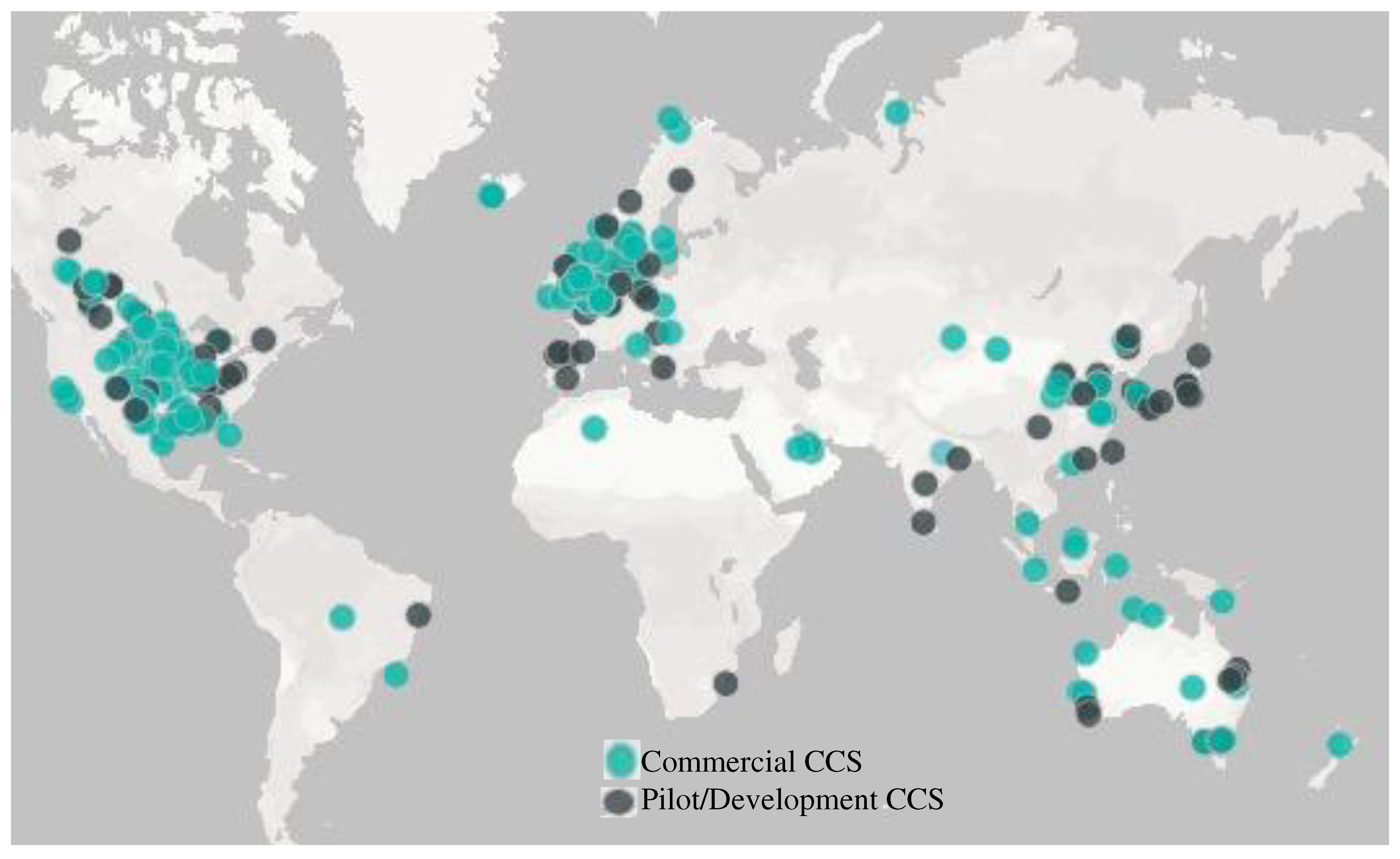
Figure 2.
Schematic Illustration of Various Geological Storage Systems for CO2 (Courtesy CO2CRC, 2015).
Figure 2.
Schematic Illustration of Various Geological Storage Systems for CO2 (Courtesy CO2CRC, 2015).
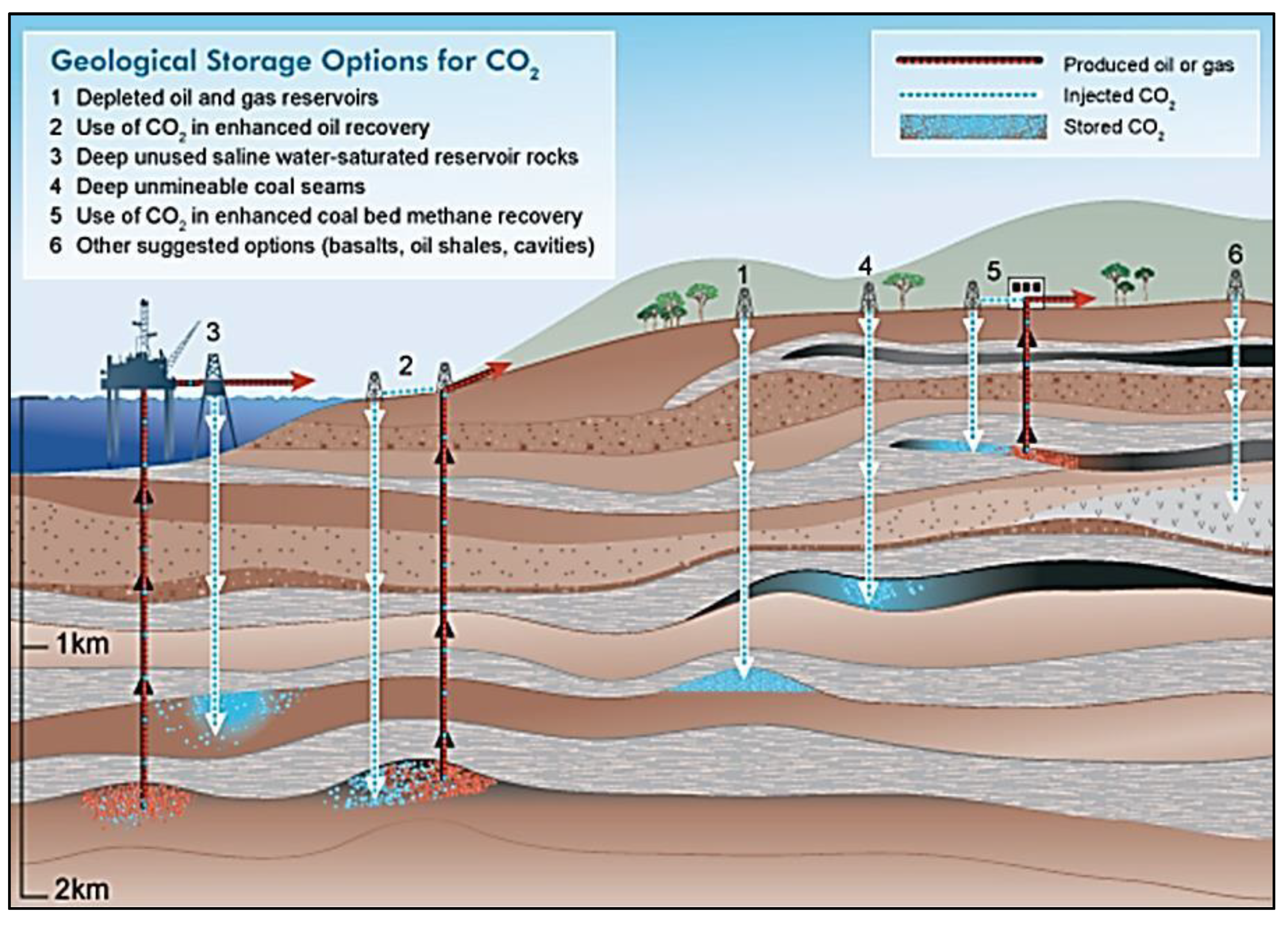
Figure 3.
Illustrate the Major 4 CO2 Trapping Subsurface systems (Zhao et al. 2014).
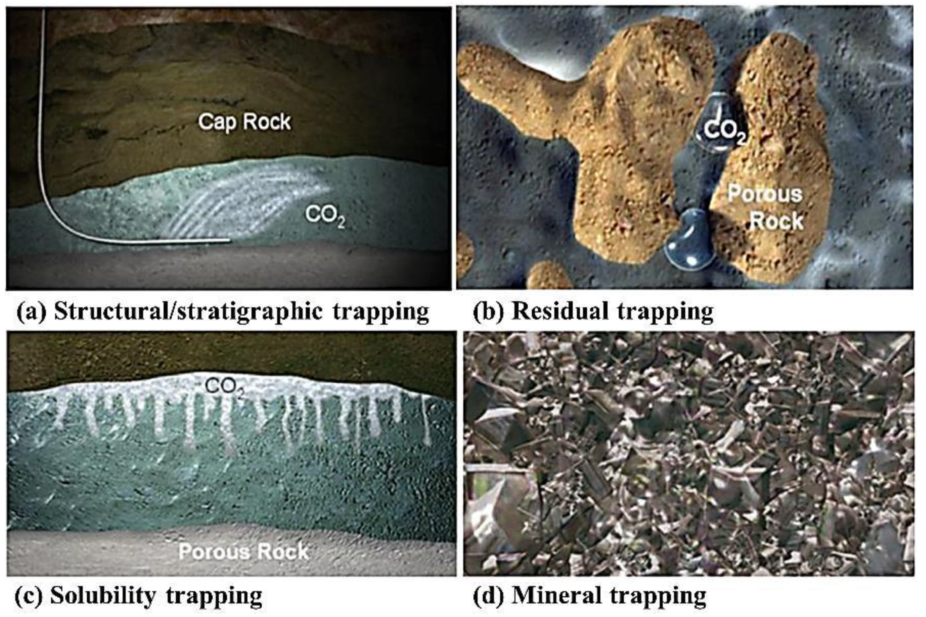
Figure 4.
Illustration of Hydrate formation Diagram sequestration with its CO2 Hydrate Seal, (Rochelle et al. 2009).
Figure 4.
Illustration of Hydrate formation Diagram sequestration with its CO2 Hydrate Seal, (Rochelle et al. 2009).
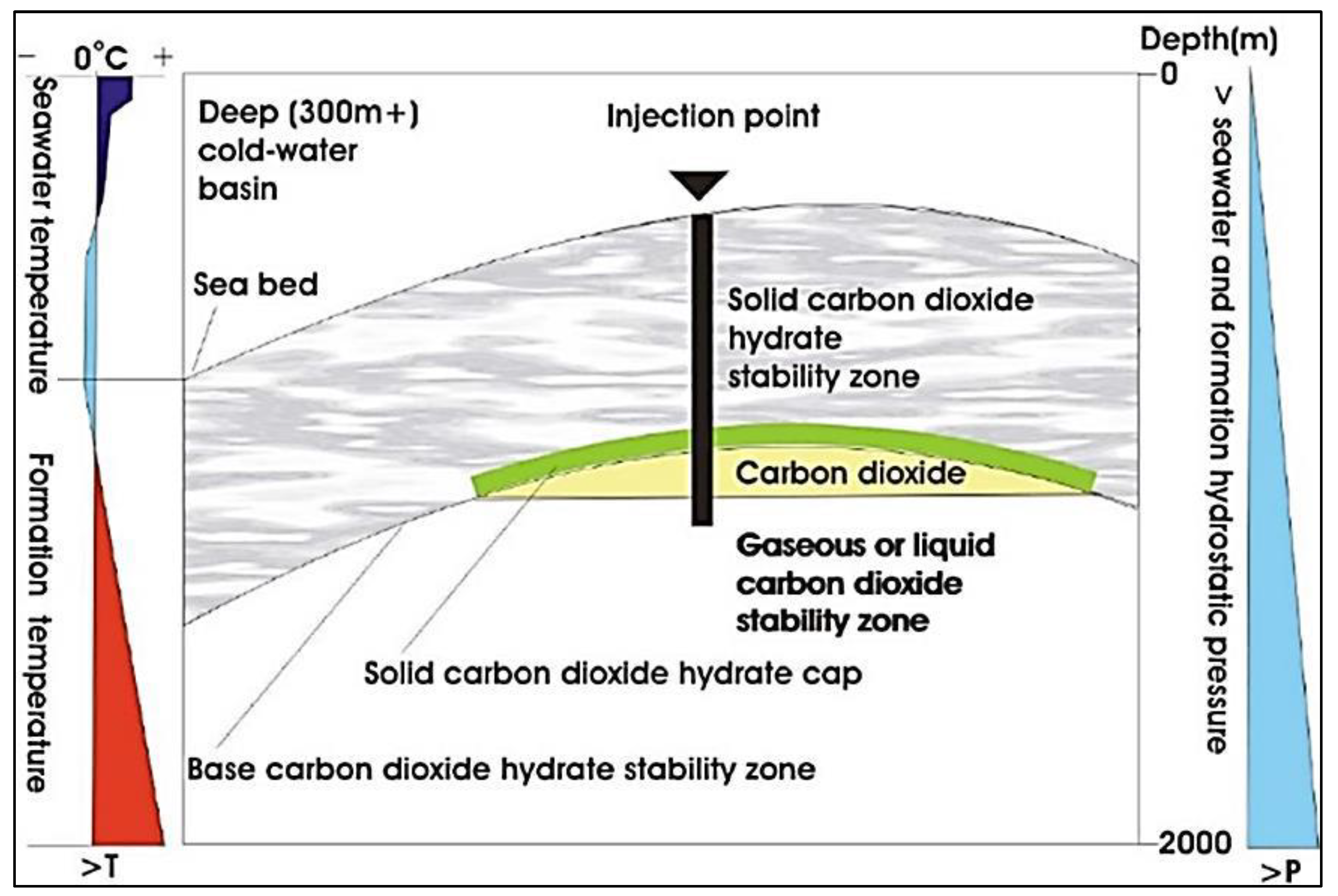
Figure 5.
Illustrates the material fluxes and process processes that are involved in the mineral carbonation of silicate rocks or industrial residues (W. Huijgen et al. 2005).
Figure 5.
Illustrates the material fluxes and process processes that are involved in the mineral carbonation of silicate rocks or industrial residues (W. Huijgen et al. 2005).
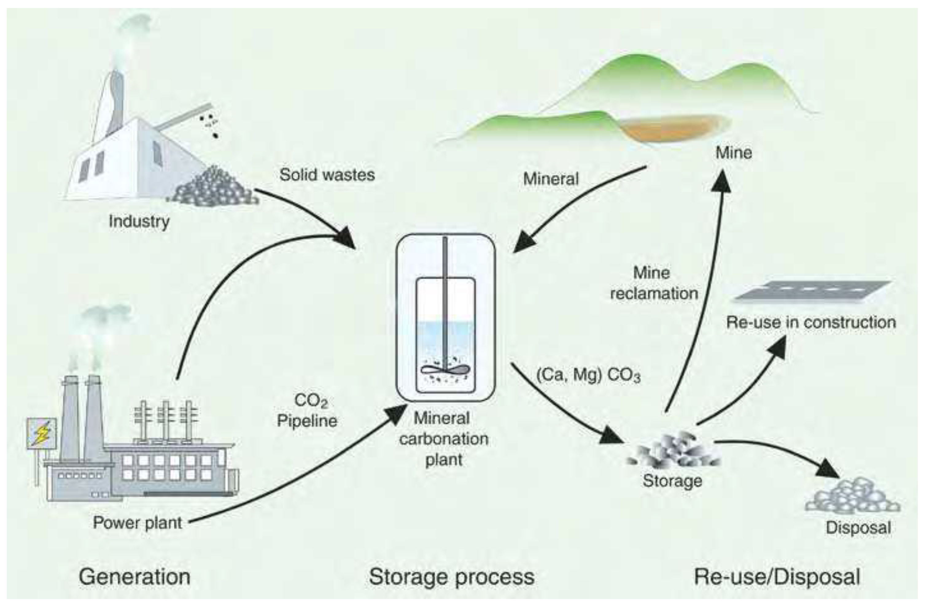
Figure 6.
An illustration of many concepts related to the storage of CO2 in the ocean. The process of ocean storage can be classified into two types: dissolution type and lake type. In the dissolution type, CO2 undergoes rapid dissolution in ocean water. On the other hand, in the lake type, CO2 exists initially as a liquid on the sea floor (CO2CRC).
Figure 6.
An illustration of many concepts related to the storage of CO2 in the ocean. The process of ocean storage can be classified into two types: dissolution type and lake type. In the dissolution type, CO2 undergoes rapid dissolution in ocean water. On the other hand, in the lake type, CO2 exists initially as a liquid on the sea floor (CO2CRC).
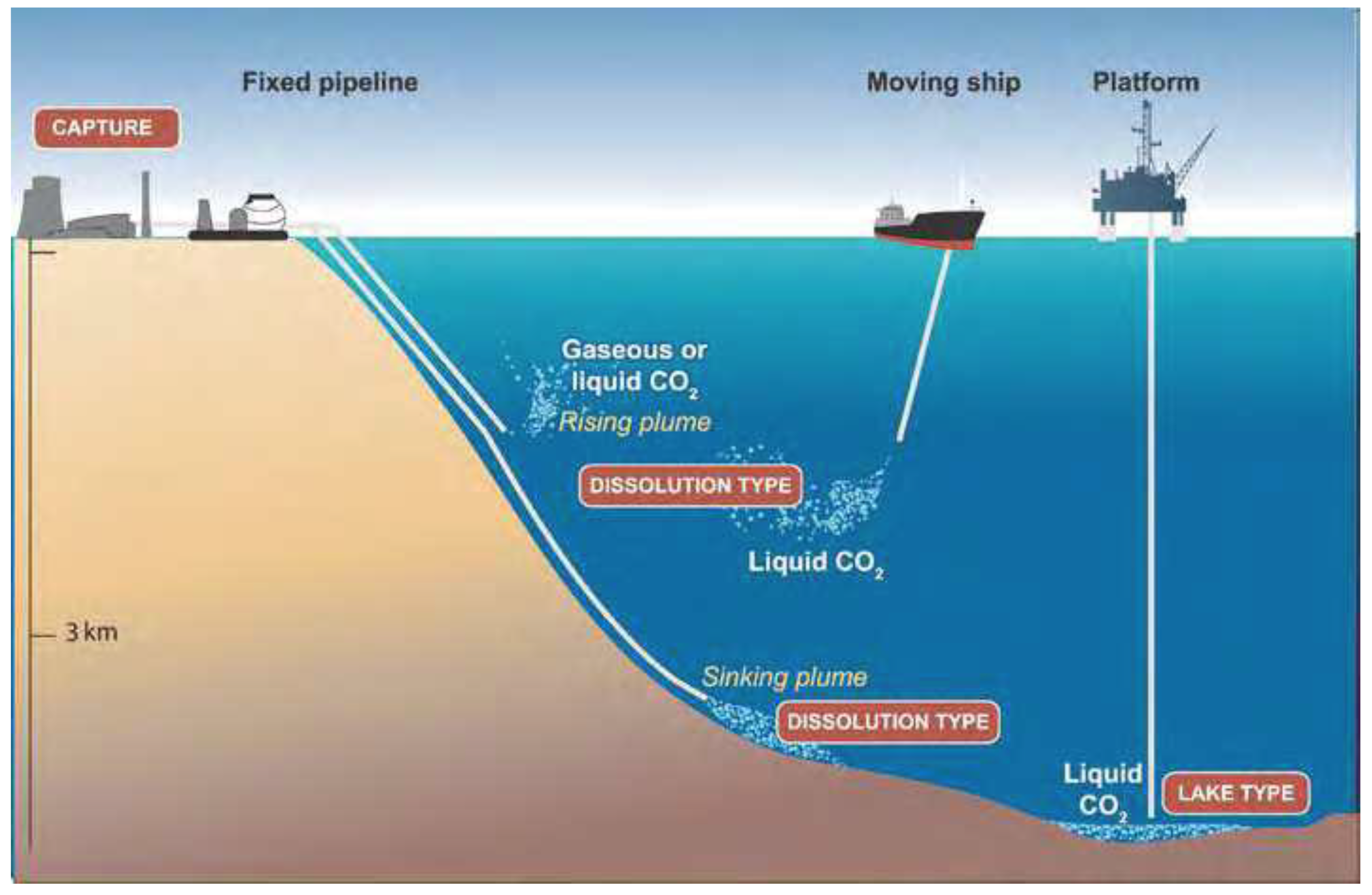
Disclaimer/Publisher’s Note: The statements, opinions and data contained in all publications are solely those of the individual author(s) and contributor(s) and not of MDPI and/or the editor(s). MDPI and/or the editor(s) disclaim responsibility for any injury to people or property resulting from any ideas, methods, instructions or products referred to in the content. |
© 2023 by the authors. Licensee MDPI, Basel, Switzerland. This article is an open access article distributed under the terms and conditions of the Creative Commons Attribution (CC BY) license (http://creativecommons.org/licenses/by/4.0/).
Copyright: This open access article is published under a Creative Commons CC BY 4.0 license, which permit the free download, distribution, and reuse, provided that the author and preprint are cited in any reuse.


