
Submitted:
21 September 2023
Posted:
25 September 2023
You are already at the latest version
Abstract
Since the controllers of the variable speed seawater pump and the 3-way valve of a ship central cooling system receive the feedback signal from the same output, the two controllers may interfere and operate inefficiently under certain conditions. Therefore, studying an efficient control tuning method for the central cooling water system is necessary. The central cooling water system was modeled in this study using MATLAB Simulink, utilizing actual operation data, and unknown parameters are estimated to fine-tune. The model is then verified using another operating data set. Additionally, transfer functions are developed for freshwater output temperature against 3-way valve openness input and seawater pump motor electric power frequency input. Then, the two PI controllers are tuned through the Internal Model Control guide, supposing the two systems are decoupled. Moreover, the modified IMC tuning method is suggested for the seawater pump system, which has larger time constants because of a heat exchanger. This method simplifies combining the two PI controller tuning, enhancing the seawater pump's overall efficiency and 3-way valve operation. This study determined that the proposed tuning methods through the IMC guide confirmed the efficiency of controlling the seawater pump speed and 3-way valve with reasonable control of freshwater outlet temperature.
Keywords:
Ship central cooling system
; MISO
; IMC
1. Introduction
Efficient control of the ship’s central cooling system with a variable speed control of the seawater pump is essential for maintaining steady temperatures and ensuring proper onboard equipment function [1,2,3,4]. This study focuses on two control applications within the central cooling system: regulating the openness of the 3-way valve and controlling the rotation speed of the seawater(S.W.) pump. Both the objectives of the controllers contribute to achieving the desired outlet temperature of the freshwater(F.W.).
Harmonizing the control actions of the two controllers is essential to ensure the smooth and coordinated operation of the ship’s central cooling system [5,6,7]. As the 3-way valve regulates freshwater flow into the heat exchanger(HEX) and bypasses the flow, it plays a crucial role in controlling the sudden change in the inlet freshwater temperature. The system can effectively manage temperature fluctuations and maintain stable cooling performance by adjusting the valve’s openness. On the other hand, the seawater pump controls the quantity of seawater circulation throughout the heat exchanger. It indirectly impacts the freshwater outlet temperature by adjusting the flow rate, allowing for efficient heat transfer and temperature regulation.
Finding the balance between the control actions of the 3-way valve and the seawater pump is a challenge. If the 3-way valve operates too aggressively, constantly changing its position. In that case, it can lead to unstable temperature control and inefficient energy usage. Conversely, if the seawater pump operates at a high rotation speed, it may result in excessive energy consumption and unnecessary stress on the equipment. Therefore, it is essential to harmonize the control actions of the two controllers to maintain temperature stability with energy efficiency [6,8].
In order to improve that challenge, two controller tuning methods are considered. The first method is applying the IMC(Internal Model Control) method, which is well-known for its effectiveness in handling systems with time delays and complex dynamics [9,10,11]. Fine-tuning the controllers with the IMC method necessitates decoupling the two systems and developing their transfer functions [12]. However, the first proposed IMC-based PI controller tuning method is to suppose that the two systems are not affected by each other. This method effectively tunes the PI controller to regulate the 3-way valve openness and seawater pump rotation speed.
The second proposed method involves setting the integral gain larger than the proportional gain for the seawater pump rotational speed PI controller derived from the IMC method. This adjustment by switching the proportional and integral gains emphasizes the importance of maintaining a lower rotational speed for the seawater pump. Increasing the integral gain relative to the proportional gain, the controller emphasizes eliminating steady-state errors and controlling the pump speed at a lower level, thereby promoting energy efficiency.
Simulation-based evaluations are conducted using a ship’s central cooling system model to assess the performance of both tuning methods. The simulation results demonstrate the effectiveness of the IMC-based PI controller tuning method in achieving temperature stability and efficiently running through step disturbances of F.W. and S.W. supply temperature. Additionally, the proposed adjustments for the seawater pump rotational speed controller show the results in reducing S.W. pump speed while maintaining the desired cooling performance.
This paper addresses the simple way of tuning the 3-way valve and the seawater pump controllers in the ship’s central cooling system, one of the multi-input single-output (MISO) systems. The goal is to achieve stable temperature control and reduced S.W. pump motor rotation speed that is much related to energy efficiency. The proposed tuning methods allow for the coordinated operation of the two controllers, resulting in improved system performance and reduced S.W. pump speed. The research outcomes contribute to advancing ship application control techniques, ensuring central cooling systems’ smooth and efficient operation.
2. Simulation Modeling of the Ship Central Cooling System
2.1. Configuration of Central Cooling System on a Ship
The central cooling system of the actual ship intended for modeling is shown in Figure 1. It consists of a seawater pump that supplies seawater, a freshwater pump that circulates freshwater, a heat exchanger that cools the hot freshwater with cold seawater, and a three-way valve that bypasses the supply of hot freshwater to the heat exchanger.
Figure 1.
An example of a central cooling system on a ship.
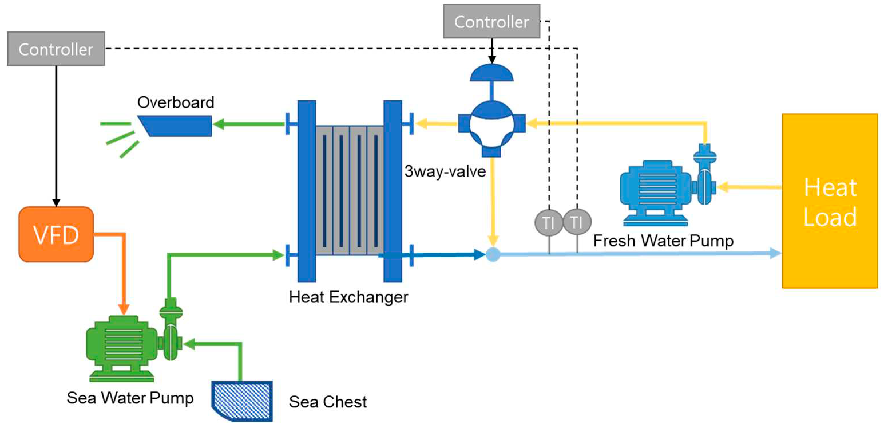
The freshwater pump circulates the freshwater at a constant rotational speed to cool the heat load. The heated freshwater, at approximately 38-43℃, is supplied to the central cooling system. The three-way valve regulates the freshwater flow rate, determining whether it is supplied to the heat exchanger or bypassed. The low-temperature seawater cools the freshwater supplied to the heat exchanger. The cooled freshwater is mixed with the high-temperature freshwater that bypasses the heat exchanger through the three-way valve. The combined freshwater then returns to the heat load.
On the other hand, the low-temperature seawater is supplied to the heat exchanger through the seawater pump. The seawater pump is driven by a variable-speed motor controlled by an inverter. By changing the voltage frequency of the input power supplied to the seawater pump motor, the amount of seawater supplied to the heat exchanger can be varied.
2.2. Configuration for Simulation
Figure 2.
Modeling of the central cooling system.
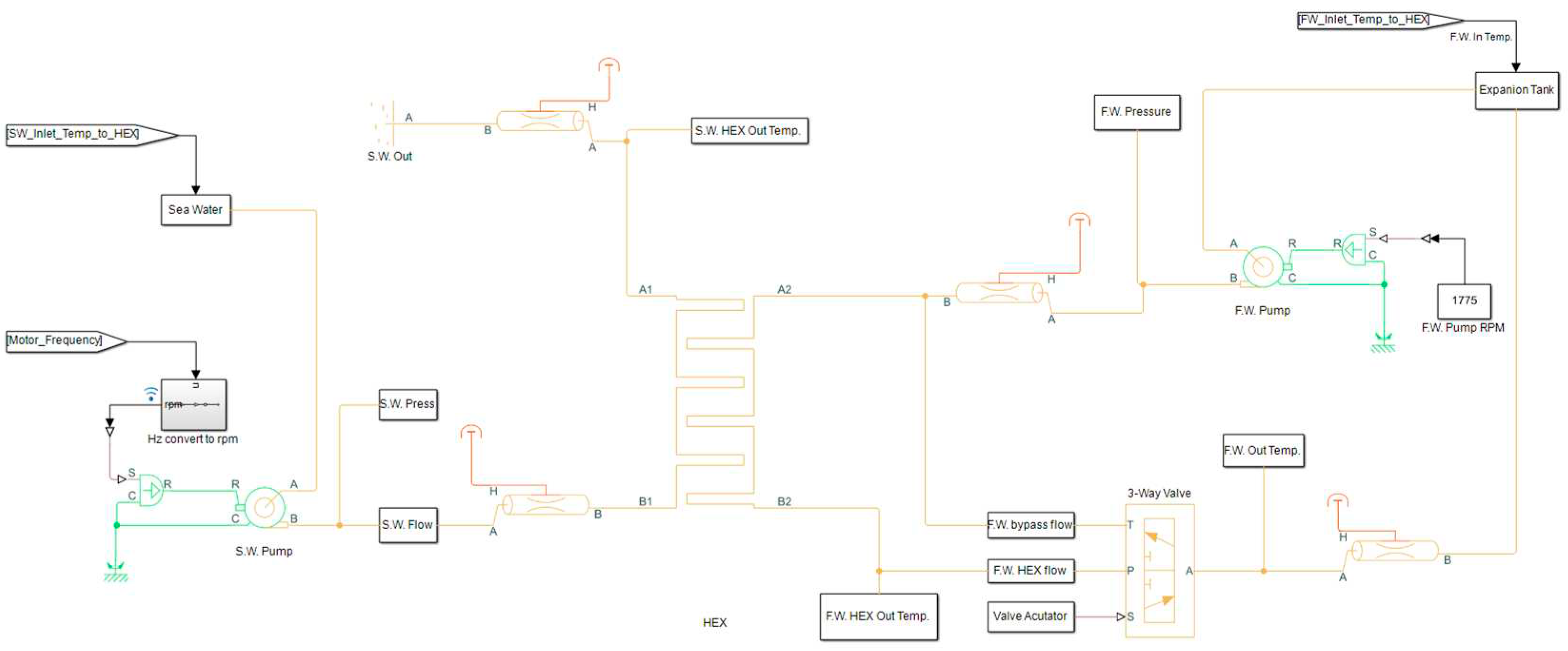
The parameter values for each pump (freshwater pump and seawater pump), three-way valve, and heat exchanger model are referred to in the datasheet information of each piece of equipment [16,17,18].
The freshwater pump is driven by a 4-pole, 3-phase, 440V, and 60 Hz motor. Referring to the FAT (Factory Acceptance Test) report and considering slip, it is modeled to rotate at a constant speed of 1775 rpm. The seawater pump also uses a motor with the exact specifications of the freshwater pump. However, the frequency input to the motor can vary from 30 to 60 Hz through an inverter. The actual variable speed achievable by the seawater pump motor, considering slip, is set to a maximum of 1775 rpm. The minimum speed is set at 887 rpm, based on the motor input frequency of 30 Hz. Additionally, the suction pressure of the seawater and freshwater pump is set based on the pressure measured by the suction gauge when each pump is stopped.
The three-way valve directs the bypass flow of freshwater through the T port, freshwater from the heat exchanger through the P port and the combined freshwater to the output through the A port in Figure 2. The bypass flow controlled by the actuator is set to vary linearly. Furthermore, the offset of the T and P ports is set to 0 so that when the T port is fully open, the P port is completely closed, and vice versa.
Various necessary parameter values such as the heat exchanger’s surface area, overall heat transfer coefficient (OHTC), thermal conductivity, pressure drop, and pipe sizes are referred to in the datasheet and FAT report of the heat exchanger.
2.3. Tunning for the Simulation Model
Based on Figure 2, the modeling was done using each piece of equipment’s actual FAT reports and datasheets. However, it is challenging to obtain simulation results that closely resemble reality due to factors such as pipeline roughness, the thermal mass of the heat exchanger, and wall thermal resistance, which are not available in the equipment’s datasheet. Therefore, to achieve simulation results that approximate reality, additional parameter values not found in the datasheet are sought using actual operating data.
The actual operating data includes pressure data for the freshwater pump and temperature data for the freshwater outlet of the three-way valve, recorded at intervals of 10 seconds. The remaining data is collected at intervals of 60 seconds.
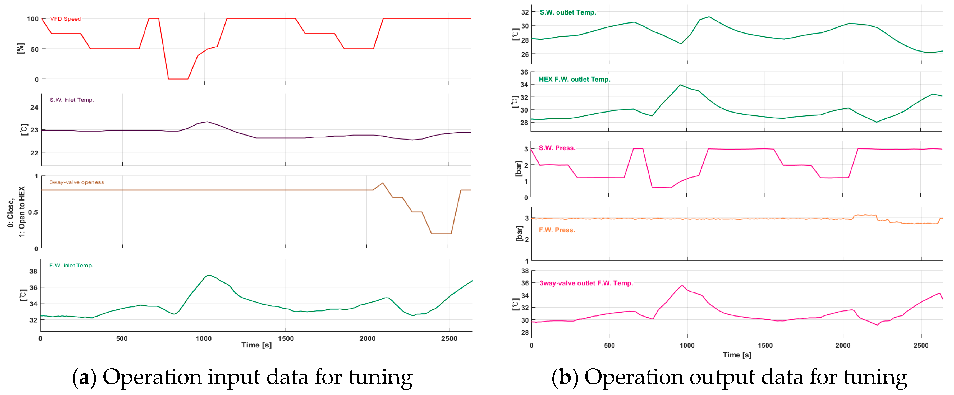
The simulation of the central cooling system using the actual operating data from Figure 3 is performed. The input data for the model includes the voltage frequency of the seawater pump motor, seawater inlet temperature, the opening degree of the three-way valve, and the freshwater inlet temperature. From 0 to 1000 seconds, the opening degree of the three-way valve is fixed at 0.8, and only the rotational speed of the seawater pump is varied. Then, from 2000 to 2600 seconds, the rotational speed of the seawater pump is fixed at its maximum, and only the three-way valve opening is varied. When the central cooling system is input with the data from Figure 3a, the actual output is represented in Figure 3b. MATLAB Parameter Estimator is used to approximate the output of the modeled central cooling system to match Figure 3b.
Figure 3.
Operation data for the simulation model tuning of the central cooling system in a ship.
2.4. Verification for the Simulation Model
The tuned model is validated using another set of actual operating data. The input data includes the voltage frequency of the seawater pump motor, seawater inlet temperature, the opening degree of the three-way valve, and the freshwater inlet temperature. The output data includes the seawater outlet temperature of the heat exchanger, freshwater outlet temperature of the heat exchanger, seawater pressure, freshwater pressure, and the freshwater outlet temperature of the three-way valve.
Among the results, the seawater and freshwater outlet temperatures of the heat exchanger and the freshwater outlet temperature of the three-way valve are compared with the corresponding simulated values obtained from the simulation.
Figure 4a shows the seawater temperature at the heat exchanger outlet, comparing the actual operating data with the simulation results. After the simulation starts in 300 seconds, the result is approximately 0.7 °C lower than the actual operating data.
Figure 4.
Comparing operation data and simulation output.
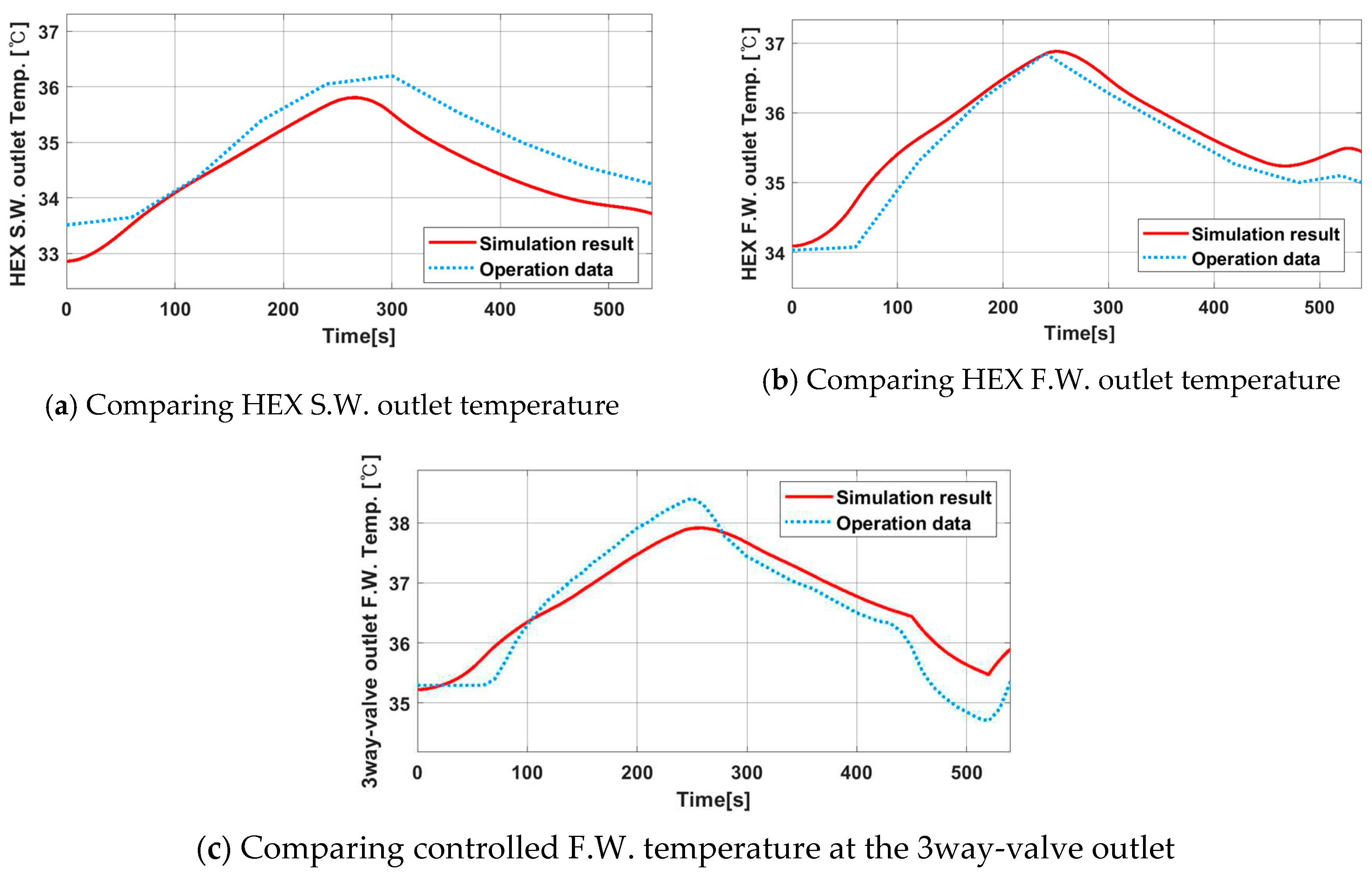
Figure 4b shows the freshwater temperature at the heat exchanger outlet, comparing the actual operating data with the simulation results. The maximum difference between the simulation results and operating data is +0.4 °C.
Figure 4c shows the freshwater temperature at the outlet of the three-way valve, comparing the actual operating data with the simulation results. The maximum deviation from the actual operating data is +0.7 °C, while the minimum deviation is -0.6 °C, using the actual operating data as a reference.
The fine-tuned simulation model is verified through the simulation result is close to the operation data, as shown in Figure 4.
3. First Proposed IMC-Based PI Controller Tuning Method
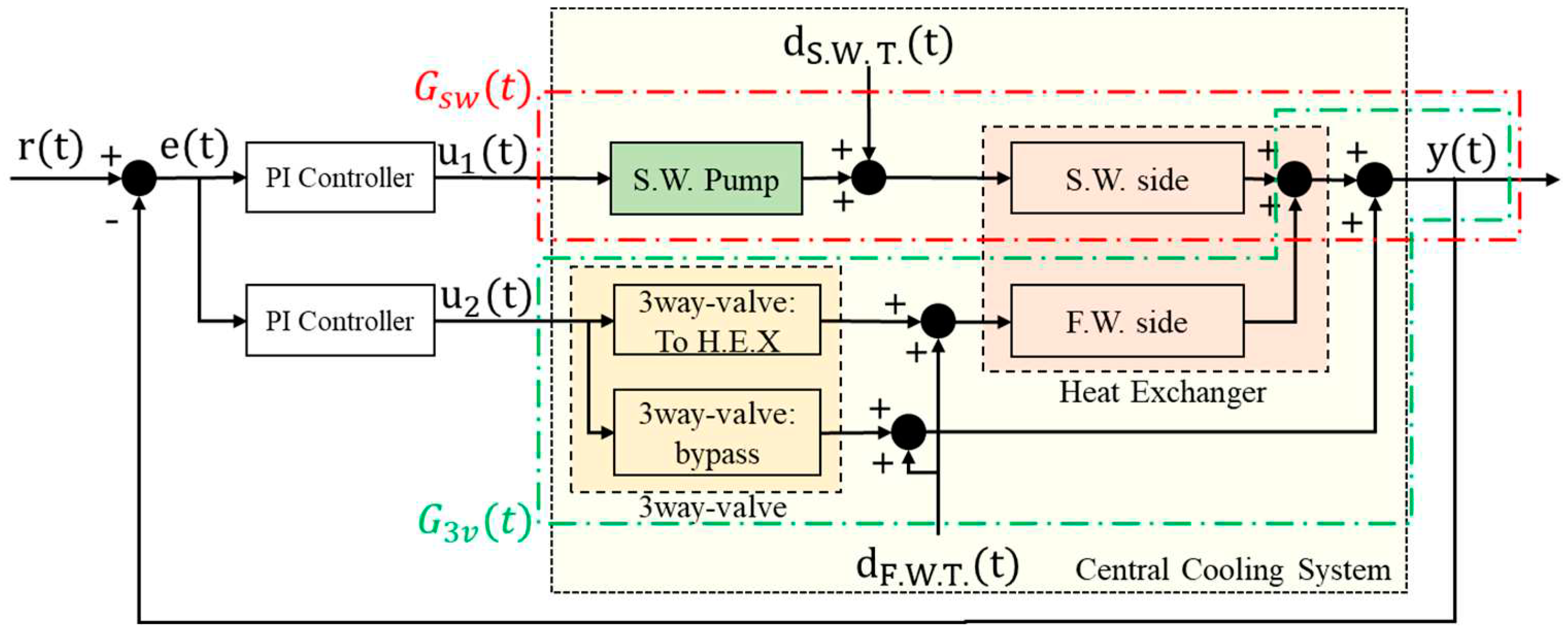
The systems transfer functions are required to design an IMC-based PI controller. In this case, we need to determine the transfer functions of the system relating the voltage frequency input of the seawater pump to the freshwater output temperature and the opening degree input of the three-way valve to the freshwater output temperature . Even though the actual systems and are not independent and can influence each other, we assume that they do not affect each other and calculate their transfer functions accordingly. That makes it much easier to get the transfer functions. Figure 5 shows the transfer functions for and .
Figure 5.
The control diagram of the central cooling system.
3.1. Finding Transfer Functions
A step input is applied for each of the two systems, and the transfer functions are estimated based on the results. First, to estimate , the freshwater inlet temperature, seawater inlet temperature, and 3-way valve input are maintained at 39°C, 22°C, and fully open as 1.0, respectively, while the input voltage frequency of the seawater pump is stepped up from 30 Hz to 40 Hz. The results are shown in Figure 6. Additionally, for , the freshwater inlet temperature and seawater inlet temperature are kept the same at 39°C and 22°C, while the input power frequency of the seawater pump is maintained at 60 Hz. The 3-way valve openness is stepped from 0.5 to 0.7. The resulting changes in the freshwater output temperature for the step input are shown in Figure 6 as well.
Figure 6.
Step response of F.W. outlet temperature against seawater pump speed and 3way valve openness.
Figure 6.
Step response of F.W. outlet temperature against seawater pump speed and 3way valve openness.
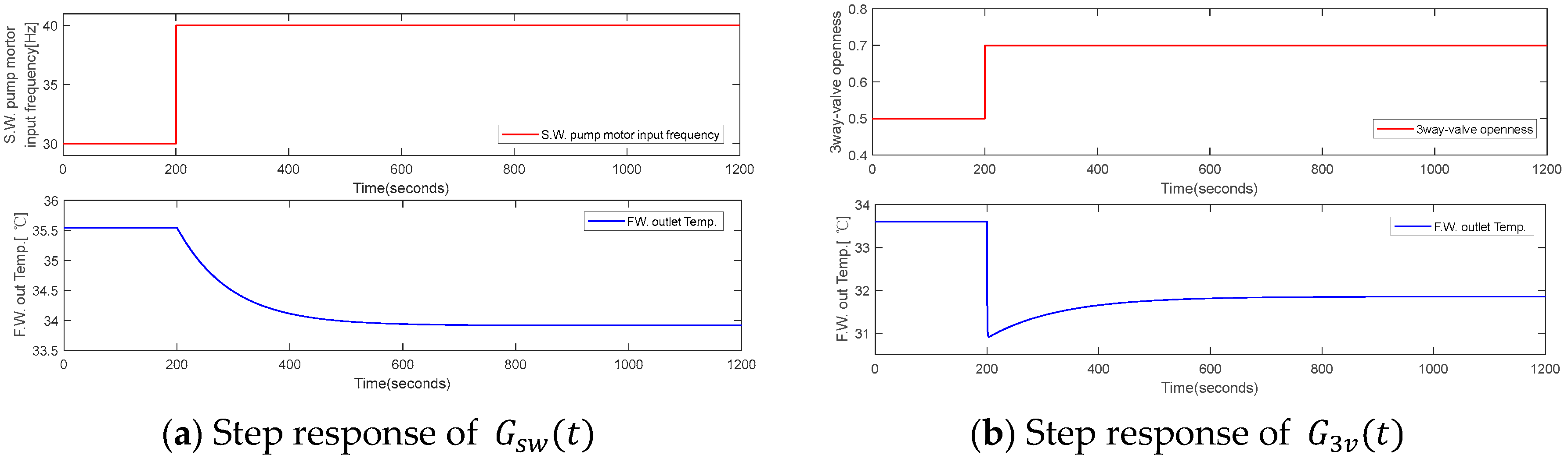
The transfer functions are obtained using Matlab’s Parameter Estimator based on the step response. is estimated as a first-order system and system is estimated as a second-order system, resulting in Equations (3.1) and (3.2), respectively. And the abbreviations used for IMC model are listed in Table 1.

Table 1.
Nomenclature.
| Symbol | Description |
|---|---|
| Filter function | |
| Transfer function of a plant or a system | |
| , | Gain of transfer function |
| Control gain function | |
| Integral gain | |
| Proportional gain | |
| , | IMC filter |
| Invert Plant and filter function | |
| , , , | Time constant of plant transfer function |
| Integral time | |
| System input, S.W. pump motor voltage frequency input, 3way valve openness input | |
| System output |
3.2. Deriving Control gains of IMC-Based PI Controllers
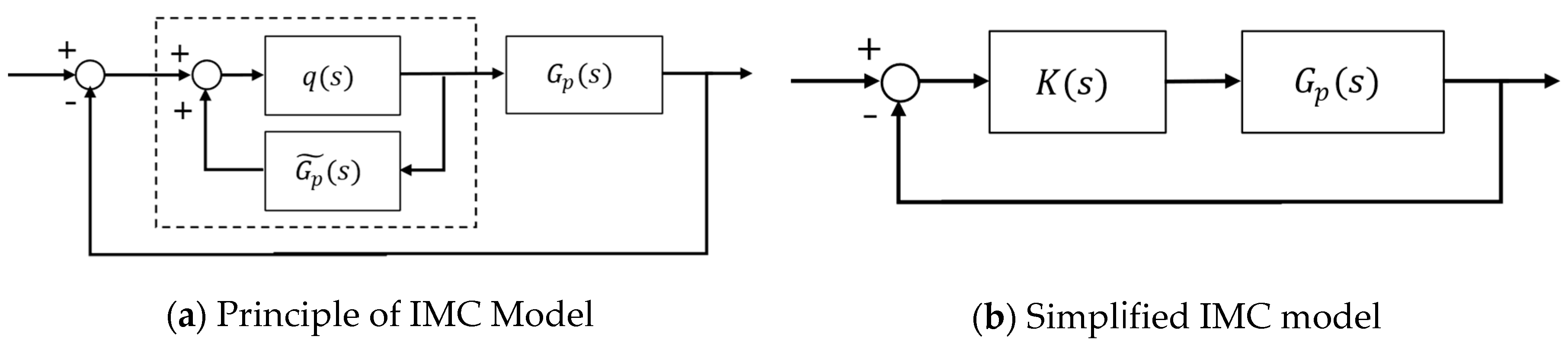
If is designated the plant to be controlled, the transfer function of the plant as , and the product of the inverse of the plant transfer function and the filter as , then the IMC principle can be represented as shown in Figure 11a. By considering and as the control gain within the dashed lines in Figure 7a, it can be represented as shown in Figure 7b. For the systems and , their respective are calculated to determine the and values of the PI controller [19].
Figure 7.
Principle of IMC.
3.2.1. Sea Water Pump System
The general mathematical modeling of the first-order transfer function, seawater pump system , is as follows, represented by Equation (3.3).
Furthermore, the product of the inverse of the transfer function of the seawater pump system and the filter, denoted as , is expressed as shown in Equation (3.4).
Therefore, the control gain in Figure 7 can be written as shown in Equation (3.5).
If the control gain in Equation (3.5) is converted into the form of a PI controller, it becomes Equation (3.6).
In that case, the gains and of the PI controller is given by Equation (3.7).
3.2.2. 3way-Valve System
The transfer function of the second-order, the 3-way valve system , is given by Equation (3.8).
Where <.
Furthermore, the filter function is assumed to be represented by Equation (3.9).
Using the same approach as in the previous section 3.2.1 to derive in the form of a PI controller, Equation (3.10) is obtained.
If ,, and , it can be expressed as shown in Equation (3.11).
If represents a lead-lag filter, then
3.3. Simulation Result of Applied IMC-Based PI controllers
Based on the equations derived in sections 3.2.1 and 3.2.2, each PI controller parameters and for the and systems are calculated by the IMC filters, as shown in Table 2.
Table 2.
Parameters of IMC-based PI controllers.
| IMC filter | |||
|---|---|---|---|
| PI controller for | = 0.85 | -688.003 | -7.2309 |
| PI controller for | = 0.90 | -16.0579 | -0.1253 |
The parameter values from Table 2 are applied to each controller, and the following conditions are used for the simulation:
- To test the performance of the controllers, step-up and step-down inputs are simultaneously applied for both freshwater and seawater temperatures, representing disturbances.
- The freshwater inlet temperature is step-up from 38°C to 42°C, referencing the operating range of the modeled ship, and maintained at 42°C for 1500 seconds. Then, it is step-down from 42°C to 38°C.
- The seawater inlet temperature is step-up from 20°C to 25°C, based on the seawater temperature in the coastal areas of Korea during spring and autumn [24], and maintained at 25°C for 1500 seconds. Subsequently, it is step-down from 25°C to 20°C.
- The upper and lower limits for the seawater pump motor voltage frequency rotation speed are set to their actual values, 60 Hz and 30 Hz, respectively.
- The upper and lower limits for the 3-way valve openness are set to their actual values, 1.0 (fully open to the heat exchanger side and fully closed to the bypass) and 0(fully close to the heat exchanger side and fully opened to the bypass).
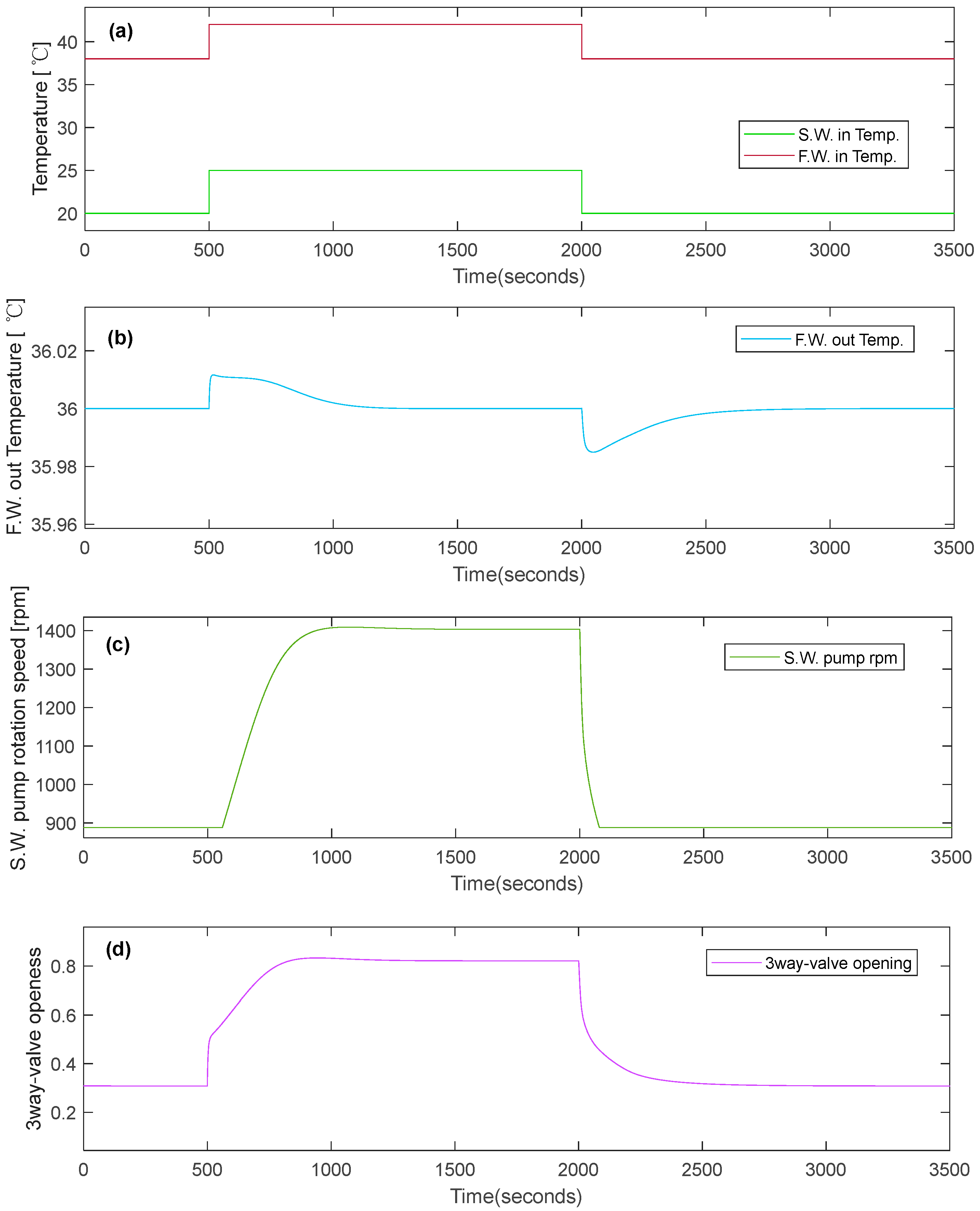
Figure 8 illustrates the simulation results. Figure 8a displays the variations in freshwater and seawater inlet temperatures. At 500 seconds, step-up inputs for both freshwater and seawater temperatures are applied. And at 2000 seconds, step-down inputs are applied.
Figure 8b shows the variation in F.W. output temperature. Despite the step-up or down disturbances, the F.W. output temperature remains within ±0.01°C of the reference temperature of 36°C. Additionally, after approximately 500 seconds following the step disturbance, the output temperature recovers to the reference temperature.
Figure 8c displays the S.W. pump rotation speed variations. After the step-up disturbance is applied, the rotation speed increases after approximately 58 seconds. This delay occurs because it takes around 58 seconds for the controller’s output to exceed the minimum rotation speed of the S.W. pump.
Figure 8d shows the variations in the 3-way valve openness. After the step-up disturbance is applied, the 3-way valve opens slightly more than 0.8.
Figure 8.
Simulation results of the applied IMC-based PI controllers.
4. Second Proposed PI Controller Tuning Method
To utilize the IMC strategy for PI controller parameter tuning, as discussed in the previous section 3.3, requires iterative simulations to find appropriate parameter values by adjusting and for the 3-way valve openness controller and seawater pump speed controller. Additionally, further reducing the rotation speed of the seawater pump, which is related to achieving even greater energy savings, it is necessary to fully open the 3-way valve and minimize the bypass flow of fresh water after applying step disturbances.
Therefore, fine-tuning the PI controller parameters necessitates repeated simulations to strike the right balance between energy efficiency and effective F.W. temperature control performance, considering both the 3-way valve control and seawater pump speed control. So, the following method is proposed for tuning the PI controllers.
Leveraging the characteristic that the response of the F.W. output temperature to the frequency input of the S.W. pump motor is slower than the response to the 3-way valve openness input, the IMC strategy is adopted. Initially, following the IMC strategy, the proportional gain and integral gain of the PI controller are derived. The IMC filter is 0.9 which is less than 1 as giving a weak effect of the filter. And is set 95 similar to the time constant of the S.W. pump transfer system on Equation (3.1).
Subsequently, for the PI controller related to the F.W. output temperature system with respect to the S.W. pump power frequency input, the values of proportional gain and integral gain are swapped, ensuring that the integral gain exceeds the proportional gain. The detailed sequence of steps is as follows:
- For the PI controller of the freshwater output temperature system based on the 3-way valve openness input, the gains are computed using the smaller of the two-time constants, and , as defined in Equations (3.11) and (3.12).
- The value of is set slightly below 1.0, specifically at 0.9.
- The value of is adjusted to 95, corresponding to the time constant value 95.147 from Equation (3.1), thereby determining the PI controller’s integral gain and proportional gain values.
- The S.W. pump rotation speed controller’s integral gain and proportional gain are interchanged.
This process ensures an effective tuning strategy leveraging the distinct response characteristics of the system to the 3-way valve openness and seawater pump power frequency inputs. As a result, in response to abrupt changes in freshwater and seawater input temperatures, the system rapidly restores the freshwater output temperature to the reference temperature by adjusting the 3-way valve openness. Subsequently, any discrepancies in the freshwater output temperature caused by variations in the freshwater flow rate due to changes in the 3-way valve openness are prevented from causing deviations from the reference temperature again. That is achieved through the significant integral gain of the controller, which leads to adjustments in the seawater pump rotation speed. By employing the method described above, the parameters of the PI controller are determined, as shown in Table 3.
Table 3.
Parameters of proposed PI controllers.
| IMC Filter | |||
|---|---|---|---|
| PI controller for | = 95 | -0.0647 | -6.1558 |
| PI controller for | = 0.9 | -0.0595 | -0.1253 |
*Swapped and gains for PI controller of S.W. pump from the traditional IMC method
4.1. Simulation result with proposed PI controllers
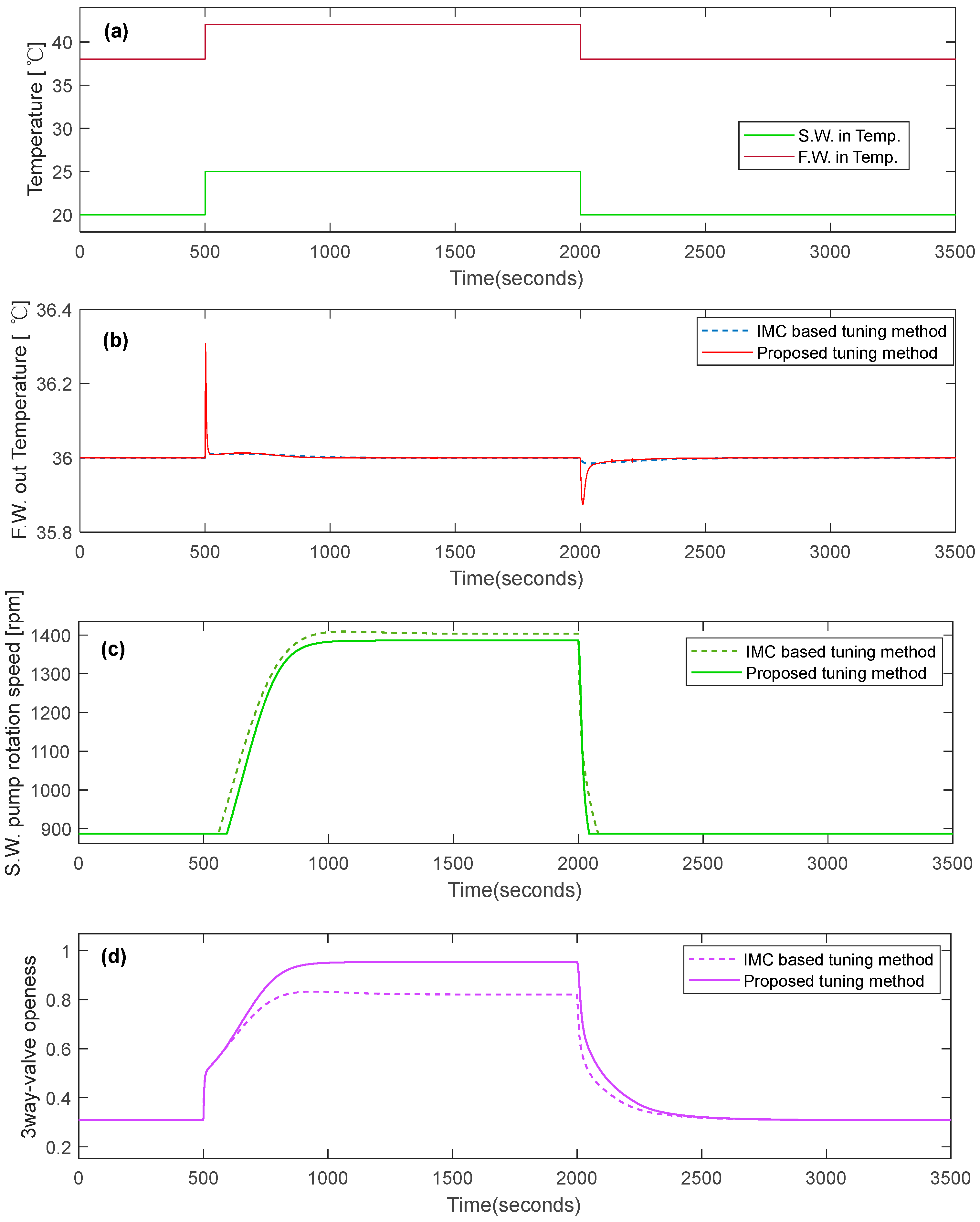
The simulation conditions and methods remain consistent with those performed in Section 3.3. The subsequent Figure 9 compares the simulation results of the central cooling system using controllers tuned with the IMC-based method discussed in Section 3.3 and the proposed method.
In Figure 9 (b), when subjected to step-up inputs for both freshwater and seawater temperatures, the overshoot of the freshwater output temperature using the proposed tuning method is approximately 0.3°C higher than that of the IMC-based tuning method. Moreover, the proposed tuning method achieves a recovery time within 0.1°C of the desired value for the freshwater output temperature in about 19 seconds. For step-down inputs in both temperatures, the proposed tuning method exhibits an overshoot of about 0.1°C larger than the IMC-based tuning method, and the recovery time within 0.1°C is approximately 15 seconds. The control performance of the freshwater output temperature in response to disturbances in freshwater and seawater temperatures is superior in the IMC-based tuning method.
However, concerning the seawater pump rotation speed significantly related to efficient energy usage, the proposed tuning method operates the pump at a lower speed. As shown in Figure 9c, after a step-up disturbance input, comparing the seawater pump rotation speed following the recovery of the freshwater output temperature, the proposed tuning method results in an approximately 18 rpm lower speed compared to the IMC-based tuning method. Before the step-up disturbance and after the step-down disturbance, the seawater pump rotation speed remains at around 887 rpm for both methods. This is because the minimum power frequency of the seawater pump motor inverter is 30 Hz. The larger overshoot in the freshwater output temperature using the proposed tuning method is due to the delayed increase in the seawater pump rotation speed after the step-up disturbance, occurring around 34 seconds later compared to the IMC-based tuning method.
Furthermore, the 3-way valve in the proposed tuning method, as illustrated in Figure 9d, is more open on the heat exchanger side, regulating the flow to allow more F.W. water for cooling compared to the IMC-based tuning method.
Figure 9.
Comparing the simulation results of the proposed and IMC running method
5. Conclusion
The central cooling system used in ships was modeled for simulation tests. In order to improve the accuracy of simulations, the central cooling system was tuned using actual operational data. The tuned central cooling system was validated using another set of operational data. This process achieved a relatively realistic approximation of the central cooling system.
Transfer functions for the response of the freshwater output temperature from variations in seawater pump rotation speed and 3-way valve openness were derived for tuning PI controllers using the IMC (Internal Model Control) guidelines. Despite the mutual influence between variations in seawater pump rotation speed and 3-way valve openness on the freshwater output temperature, a simplified approach assumed the independence of the two control loops for IMC tuning. Appropriate controller gain values were obtained, and multiple simulations using the derived transfer functions and IMC filter values were conducted to find efficient tuning configurations.
However, tuning both controllers using IMC guidelines requires finding the proper filter values that allow seawater pump rotation speed and 3-way valve openness to be controlled efficiently without interference while changing two IMC filter values. In order to improve that challenge and achieve a more open 3-way valve and lower S.W. pump rotation speed, the tuning method of the controllers was proposed based on the characteristics of time constants of the transfer functions. By swapping the proportional and integral gains of the S.W. pump speed PI controller obtained through the IMC method and by increasing the integral gain more than the proportional gain, interference between the control of F.W. output temperature and 3-way valve openness was reduced, leading to efficient control of S.W. pump rotation speed and 3-way valve openness. Moreover, compared to the control combination of the two PI controllers tuned using the first proposed IMC method, the second proposed tuning resulted in lower S.W. pump rotation speed in response to disturbances in SS.W. and F.W. input temperatures.
In conclusion, this study demonstrated two aspects regarding applying two controllers in a central cooling system. Firstly, it presented a method to tune the gains of two PI controllers using the IMC approach. Secondly, it verified that the proposed tuning method for the two controllers enables a more uncomplicated adjustment of the PI controller gains when the time constants are known and more efficient control of S.W. pump rotation speed.
Author Contributions
“Conceptualization, T.Y Jeon.; methodology, T.Y Jeon.; formal analysis, T.Y Jeon; writing—original draft preparation, T.Y Jeon.; writing—review and editing, B.G Jung
Funding
Not applicable.
Institutional Review Board Statement
Not applicable.
Informed Consent Statement
Not applicable.
Data Availability Statement
No applicable.
Acknowledgments
The central cooling system operation data is from T/S Hanara Training Ship of Korea Ocean & Maritime University.
Conflicts of Interest
The authors declare no conflict of interest.
References
- Dere, C.; Deniz, C. Load optimization of central cooling system pumps of a container ship for the slow steaming conditions to enhance the energy efficiency. J Clean Prod 2019, 222, 206-217. [CrossRef]
- Theotokatos, G.; Sfakianakis, K.; Vassalos, D. Investigation of ship cooling system operation for improving energy efficiency. J Mar Sci Technol 2017, 22, 38-50. [CrossRef]
- Su, C.; Chung, W.; Yu, K. An energy-savings evaluation method for variable-frequency-drive applications on ship central cooling systems. IEEE Trans Ind Appl 2013, 50, 1286-1294. [CrossRef]
- X. Qi; J. Jiao; T. Tang; Y. Chu; S. Shi Study on optimize design of central cooling system, - 2017 IEEE 2nd Information Technology, Networking, Electronic and Automation Control Conference (ITNEC), 2017; , pp. 1512-1515.
- ZHOU, Z. Optimization Design of Ship Central Cooling System Based on Variable Frequency Control. Ship & Boat 2020, 31, 71.
- Jeon, T.; Lee, C.; Hur, J. A Study on the Control Solution of Ship’s Central Fresh Water-Cooling System for Efficient Energy Control Based on Merchant Training Ship. Journal of Marine Science and Engineering 2022, 10, 679. [CrossRef]
- S. V. Giannoutsos; S. N. Manias A Data-Driven Process Controller for Energy-Efficient Variable-Speed Pump Operation in the Central Cooling Water System of Marine Vessels. IEEE Transactions on Industrial Electronics 2015, 62, 587-598. [CrossRef]
- Lee, C.; Jeon, T.; Jung, B.; Lee, Y. Design of energy saving controllers for central cooling water systems. Journal of Marine Science and Engineering 2021, 9, 513. [CrossRef]
- Chien, I. IMC-PID Controller Design - An Extension. IFAC Proceedings Volumes 1988, 21, 147-152. Available online: https://www.sciencedirect.com/science/article/pii/S1474667017538161. [CrossRef]
- Chawankul, N.; Budman, H.; Douglas, P.L. The integration of design and control: IMC control and robustness. Comput Chem Eng 2005, 29, 261-271. Available online: https://www.sciencedirect.com/science/article/pii/S0098135404002583. [CrossRef]
- Rivera, D.E.; Morari, M.; Skogestad, S. Internal model control: PID controller design. Industrial & engineering chemistry process design and development 1986, 25, 252-265.
- Pandey, S.K.; Dey, J.; Banerjee, S. On internal model control (imc) of mimo systems. IETE Journal of Research 2021, 1-18. [CrossRef]
- MATLAB Help Center - Simscape 3-Way Directional Valve(TL). Available online: https://www.mathworks.com/help/physmod/hydro/ref/3waydirectionalvalvetl.html (Accessed on .9.18 2023).
- MATLAB Help Center- Simscape Heat Exchanger(TL-TL). Available online: https://www.mathworks.com/help/releases/R2020b/physmod/hydro/ref/heatexchangertltl.html (Accessed on .9.18 2023).
- MATLAB Help Center - Simscape Centrifugal Pump (TL). Available online: https://www.mathworks.com/help/releases/R2020b/physmod/hydro/ref/centrifugalpumptl.html (Accessed on .9.18 2023).
- BY Controls, I. S148, T/S Hannara, Control Valve Specification Sheet. Hanjin Heavy Industries 2018.
- Hanjin Heavy Industry S148,T/S Hannara, Plate Cooler Final. 2018.
- Shin Shin Machinery Co., L. S148, T/S Hannara, Pump Test Record. Hanjin Heavy Industries 2017.
- Bequette, W.B. Process control: modeling, design, and simulation, Prentice Hall PTR: 2003; pp. 64, 285-305.stylefix.
Disclaimer/Publisher’s Note: The statements, opinions and data contained in all publications are solely those of the individual author(s) and contributor(s) and not of MDPI and/or the editor(s). MDPI and/or the editor(s) disclaim responsibility for any injury to people or property resulting from any ideas, methods, instructions or products referred to in the content. |
© 2023 by the authors. Licensee MDPI, Basel, Switzerland. This article is an open access article distributed under the terms and conditions of the Creative Commons Attribution (CC BY) license (http://creativecommons.org/licenses/by/4.0/).
Copyright: This open access article is published under a Creative Commons CC BY 4.0 license, which permit the free download, distribution, and reuse, provided that the author and preprint are cited in any reuse.


