Submitted:
18 September 2023
Posted:
20 September 2023
You are already at the latest version
Abstract
In the recent rechargeable battery industry, lithium sulfur batteries (LSBs) have demonstrated promising candidate battery to serve as the next-generation secondary battery owing to its enhanced theoretical specific energy, economy, and environmental friendliness. Its inferior cyclability, however, which is primarily due to electrode deterioration caused by the lithium polysulfide shuttle effect, is still a major problem for the real industrial usage of LSBs. Optimization of the separator and functional barrier layer is an effective strategy for remedying these issues. In this article, the current progress based on classification and modification on functional separator is summarized. We will also describe their working mechanisms as well as the resulting LSB electrochemical properties. In addition, necessary performance for separators also will be mentioned in order to gain optimized LSB performance.
Keywords:
lithium sulfur battery
; rechargeable battery
; separator
; electrochemistry
; anode
; cathode
1. Introduction
The propagation of modern human society based on electronic industry has demanded stronger and cheaper energy storage systems. Among these, lithium ion batteries (LIBs) have been aggressively studied and developed because of their high endurance against electrochemistry variation and stable usage for application in various type of electronic devices including smart phone, mobile phone and EVs etc... Even though LIBs still suffer from limited capacity, high price, and safety issues including their flammable nature. Due to these reasons, it would be difficult for LIBs to fulfill the demand for upcoming new industrial applications, such as drones, EVs, military power supplies, and stationary electrical power station because they always demand higher capacity, safer and economically friendly rechargeable batteries1-3. In this regard, lithium sulfur batteries (LSBs) could be one of alternative candidate rechargeable battery due to their high theoretical specific capacity and energy density (1,675 mAh g-1 and 2,600 Wh Kg-1, respectively). The corresponding values for LIBs are 240 - 280 mAh g-1 and 350 - 400 Wh Kg-1, respectively. Apart from the nature from LIBs, the electrochemical reaction of LSBs is different from that of LIBs due to sulfur cathode existence and can be expressed as
S + 2Li → Li2S (E0 = 2.20 V vs. Li/Li+)
As a result, LSBs can offer 5 - 7 times higher energy density than that of LIBs. Combined with its other advantages, i.e., sulfur being naturally abundant, cheap, and a non-toxic element, LSBs can be considered as one of the candidate for next generation rechargeable batteries4-7. The typical configuration of an LSB is shown in Figure 1.
Lithium metal as being an anode and a carbon - sulfur composite is the cathode8. As ordinary battery, the separator and an electrolyte exist between the cathode and anode.
When LSB is discharged, sulfur is reduced to Li2S by a series of electrochemical reaction while forming various types of polysulfide intermediates. Figure 2 indicates a ordinary profile LSBs during charge – discharge electrochemical reaction9.
During the electrochemical reaction, sulfur is reduced to Li2Sx (x = 2 - 8) by stepwise electrochemical reaction to form each lithium sulfide compounds. The lithium polysulfide (LiPS) compound with a relatively long-chain; Li2Sx (x = 4 - 8) can be highly soluble. On the other hand, the solubility of Li2Sx (x = 2 - 4) with short-chain are less soluble compared to long chained one in the electrolyte10. The lithiation of sulfur occurs stepwise. At voltage around ~2.3 V, S8 as the solid state is reduced to soluble S82- by an initial electrochemical reaction. After that, dissolved S82- is further electrochemically reduced to S42- on the cathode. During this sequential chemical process, LiPS intermediates such as S62-, S32-, and S3 are formed11,12.
As LiPS concentration increase as this electrochemical reaction proceeds, the viscosity of the electrolyte would be enhanced. Gradual voltage decrease can be seen at this stage reaction. After these events, one can observe prolonged voltage around 2.0 – 2.2 V which is the major origin of LSB capacity. During this stage, electrochemical reaction which transforms soluble low ordered LiPS to insoluble Li2S2 or Li2S, is proceeding.
At the final stage, Li2S2 would become Li2S by reduction process. However, it should be noted that since this is the solid-solid phase reaction, this kinetics are slow due to sluggish ion diffusion. Insulate characteristics of both Li2S2 and Li2S are additional cause for slow electrochemical reductive reaction13.
In spite of these advantages, LSBs still face with obstacles for practical industrial usage. For example, sulfur as cathode active material have insulation characteristic for both electron and ion. LiPS as byproducts are formed in the liquid electrolyte (shuttle effect) during discharge process which reduce the mass and utilization of cathode sulfur. In addition, dendrite formation of lithium anode may cause fire once they reach other side of electrode by a state of battery short circuit. Furthermore, volume expansion caused by the electrochemical reaction of S to Li2S would result in loosing stability in cathode structure14,15.
Tremendous amount of effort has been carried out to overcome these problematic issues by increasing the cathode materials conductivity as well as by reducing LiPS dissolution in the electrolyte16-19. For example, conductivity increase of cathode structure is trying to be achieved by applying conductive carbon, carbon nanotube, graphene, as well as conductive polymer. To prevent LiPS dissolution in the electrolyte, various kinds of oxide, sulfide, nitride and carbide and some functional materials such as quantum dot, metal organic framework have been replaced with carbon to reduce the shuttle effect20-23.
Further challenges facing the cathode and electrolyte development for LSBs have been recently accelerated due to the strong influence upon the electrochemical properties. The key function of an LSB electrolyte is to efficiently transport Li+ ions in the battery, and this requires a high level of Li+ conductivity. The composition of electrolyte also largely influence the cathode electrode reaction as well as LiPS byproducts behavior. 24-26.
In addition to designing cathodes and electrolytes, separator is also a critical LSB component to effect its performance especially in terms of suppressing LiPS problem as separators can be reservoirs or capturing materials for polysulfide intermediates. Additionally, when separator have conductivity for example, they can behave as the second current collector for electrons which would result in enhancing the LSB electrochemical performance 27. Nevertheless, it should be mentioned here that additional separator weight by its modification should be carefully regulated for battery energy density as a whole 28.
In general, polypropylene: PP and polyethylene: PE are used as separators. Although it would be difficult for theses nonpolar and hydrophobic materials to suppress LiPS shuttle effect because lithium polysulfide has more polar nature29. As preparation procedure, direct coating, slurry coating, or filtration of functional materials onto commercial separator would be enough to make such separators in order to prevent LiPS shuttle effect. Besides LiPS suppression, such functional separators are also expected to possess catalytic activity and good mechanical strength for LSBs30.
Fortunately, this kind of process such as direct coating of functional materials ink or slurry onto separator, can be applied to industrial manufacturing process easily. Especially, important parameters including thickness, weight, size and the kind of functional materials on separator can be readily controlled and can be applied to real practical industrial process. Since commercial separators possess hydrophobic nature in general as explained above, it is more ideal to use hydrophilic materials to capture LiPS and prevent shuttle effect. Thickness, weight as well as porosity of functional layers on separator also needs to be take into consideration because they directly influence the rate of electron and lithium ion as well as liquid electrolyte uptake31.
One has to also consider the modified separators whether they are either facing anode or cathode sides. This is because the separator role will influence largely depending upon whether they are placed toward the anode or the cathode direction. Although the main issue with LSBs is the shuttle effect induced by LiPS, lithium dendrites growth during electrochemical process is another problematic issue. Lithium metal dendrites are formed by side chemical process between polysulfide and lithium metal. Thus, functional interlayers on anode side could be one of possible solution to prevent dendrite growth by placing internal layer at extra space on anode side. This kind of interlayer may act as second barrier layer against leaked LiPS from cathode side, as well as preventing dendrite physical puncture to the separator. In addition, functional interlayer or separator could decrease the interfacial resistance of metallic lithium anode by introducing lithium compatible material. Anode facing functional separator may also act as the scaffold for lithium ion in order to suppress the lithium dendrite growth32.
Compared with cathode-facing separators, anode-facing separators should have a somewhat lithiophilic nature, endowing them with a high compatibility with lithium metal, in addition to their ability to functionally suppress the shuttle effect. This will control the spatial distribution of lithium deposition during redox reactions. When these properties are optimized, they can be expected to more efficiently hinder dendritic growth of the lithium metal33.
In the following content, whether functional layers or separators are facing anode or cathode side, and material classifications of separators, their working mechanisms, resulting corresponding assembled LSB electrochemical properties, will be explained.
2. Separators Classified by Materials
2.1. Separator Material: Metal
Nanoparticle- or nanolayer-based materials can inhibit dendritic Li growth by controlling lithium nucleation34. The nanoparticles in anode-facing separators behave as nucleation sites for lithium metal during electrochemical reactions as they decrease the Gibbs free energy of lithium metal electrodeposition. Initially, lithium crystal seeds would gradually grow until they cover the entire surface of the separator surface. As process proceeds, dense lithium metal layer without dendrites are formed on the separator. Liu et al. has demonstrated this phenomenon by applying lithiophilic Mg nanoparticles to an anode, LSB prepared with this unique functional separator, exhibited high capacity retention (>80% after 400 cycles)35. Furthermore, nanoparticles morphology can confer the cathode structure with appropriate pores and voids which could be favorable lithium ion transportation channel to enhance LSB electrochemical performance. It should be noted here that Mg, Ag, and Au are also known to lower the Gibbs free energy of lithium electrodeposition.
Zuo et al. investigated the Li metal deposition phenomenon with a symmetric cell at a current density of 2.5 mA cm-2. As a result, lithium dendrites were observed on the surface of the pristine Li metal anode after electrochemical discharge process as confirmed on Figure 3a. When Ag was co-deposited, Li dendrites had tendency to fill the interspace among the Ag particles which resulting in the lateral growth (Figure 3b). When one take a look at cross-sectional SEM image, without Ag introduction, clear Li dendrites with a thickness of ∼66.3 µm were seen after 50 cycles of electrochemical charge-discharge process (Figure 3c). When Ag was introduced to Li metal, in contrast, the electrode surface with dense Ag-Li alloy layer without any Li dendrites were observed (Figure 3d). This surprising Li dendrites suppression effect of Ag introduction to Li metal anode was suggested to be due to the strong affinity of Li with Ag metal. We would like to look at one example of LIB apart from LSB. With this interesting mechanism, Li ions were deposited uniformly during electrochemical charge-discharge process. As a result, when LiFePO4|Li full cell was prepared with Ag introduced Li metal as anode, it exhibited a high cycling performance with a high specific capacity of 131 mAh g-1 after 300 cycles at 0.5 C36.
2.2. Separator Material: Ceramic
Boron nitride was applied to optimize the commercial separators owing to its intrinsic high levels of insulation and high thermal conductivity37. Boron nitride (BN) / carbon modified composite separator was prepared with coating method on separator. Figure 4a shows a schematic figure and the functions of the BN/carbon separator in an LSB. During discharge, LiPS are spreads out from the sulfur cathode towards the lithium anode metal. The carbon layer physically hinders the diffusion of the LiPS acting as the first blocking layer, and any LiPS that diffuses through the carbon layer is subsequently trapped by the BN layer acting as the second blocking layer. This BN/carbon separator was prepared by direct ink casting (ink composed of carbon nanopowder and BN nanopowder) onto a polypropylene separator via the slurry coating method. Owing to this simple procedure, large-scale separator fabrication (dimensions 150 mm long and 60 mm wide) could be achieved (Figure 4b). The prepared separator had sufficient mechanical strength and was able to resist physical twisting due to the strong level of adhesion between the separator, carbon, and BN nanopowders, having been bonded using a polyvinylidene fluoride (PVDF) binder (Figure 4c). Figure 4d shows the surface of a pristine commercial polypropylene separator, on which some distributed pores can be observed. After coating the separator with BN (particle size ~ 100 nm; Figure 4e) and carbon (particle size ~ 50 nm; Figure 4f) nanopowders, the pores were fully covered. The thicknesses of the BN layer and the carbon layer were ~7 and ~6 μm, respectively (Figure 4g). Some of the electrochemical properties of the prepared LSBs were measured. After the surface modification, lithium dendrite formation was suppressed by forming Li surface by ideal Li plating/striping process (Figure 4h). Fortunately, LiPS diffusion was mitigated by additional BN layer on separator thus results in obtaining higher LSB electrochemical performance (Figure 4i)37.
In addition to controlling the lithium metal growth and nucleation, oxide functional interlayer also could be ideal in suppressing LiPS effect. Silica (SiO2) is one such material effective for preventing the LiPS shuttle effect and improving LSB performance. One of its advantages is its abundance. Thermal stability of SiO2 is also a good feature in order to confer the separator with high thermal stability38. However, its direct contact with the cathode should be prevented as SiO2 is known to react with lithium metal39. However, it should be noted one of SiO2 coated separator example will be presented in a later section. In addition, SiO2 has high affinity with LiPS, making it suitable for suppressing the LiPS shuttle effect40. Therefore, SiO2 utilization as functional LBS separators could be one of good method. Li et al. attempted SiO2 coating of a polypropylene (PP) separator using the tetraethoxysilane (TEOS)-based sol-gel method. They have elucidated that by applying PP–SiO2 separator, electrolyte wettability and thermal stability was properly improved. As a result, rate and cyclic voltammetry performance was improved owing to suppressed LiPS shuttle effect as well as promoting lithium ion transport inside LSBs41.
Chemical stability and LiPS adsorption ability of Alumina (Al2O3) is relatively high. Hou et al. elucidated that the oxygen atom with a lone electron pair of oxide materials such as Al2O3 and SiO2, has strong dipole - dipole interactions with LiPS42. Wang et al. prepared a purely inorganic separator with Al2O3 nanowires. In general, a purely inorganic separator without any base organic polymer would have a brittleness problem compared to conventional organic PP separators. Although, the advantages of ceramic separator are higher uptake of liquid electrolyte and higher porosity. They often also exhibit improved thermal stability and enhanced conductivity compared to organic one. This mechanism can be applied for not only LSB but also LIB. For example, when alumina separator was applied for Li|LiFePO4 (LFP), the battery electrochemical characteristics were better than conventional PP separator based battery43.
Regarding LSB, He et al. prepared an Al2O3 thin film on a commercial separator on anode-facing side in order to examine the lithium dendrite formation prevention effect. It was found that the Al2O3 layer successfully mitigated the chemical reactions between LiPS and the lithium anode. They also discovered that prepared Al2O3 porous structure accelerate uniform lithium nucleation which resulted in preventing lithium dendrite growth to form smooth and dense lithium anode44.
Li6.4La3Zr1.4Ta0.6O12 (LLZTO) is the lithium ion conductive solid electrolyte and it was coated on PP separator on anode side. Smooth lithium deposition was achieved due to uniformly dispersed transportation path for lithium ion in the three dimensional structure in LLZTO. It was also clarified that lithium ion deposition was further enhanced by adding higher content of LLZTO by localizing higher content of anions. Owing to these improvements, prepared LSB presented improved electrochemical performance with better safety due to solid electrolyte stability45.
2.4. Other Functional Separator Materials
As we have seen above, a modified anode-facing separator could act as a simple barrier to push back LiPS immigration from the cathode to the anode, and this would also be expected to impede Li dendrite formation. For example, there is a kind of conducting polymer that is known to capture LiPS, promoting Li ion flux and electron transportation. Li et al. prepared a conductive polypyrrole (PPy) film for a commercial anode-facing separator and succeeded in improving LSB electrochemical properties46. They deposited the PPy film on the separator by applying an Fe-based precursor and pyrrole monomer and succeeded in obtaining PPy-modified separator (Figure 5a,b). Scanning Electron Microscope (SEM) observation of the pristine separator revealed abundant nanopores with sizes of 100–200 nm (Figure 5c). In contrast, slightly smaller nanopores with sizes of 30–50 nm were observed on the PPy-coated separator (Figure 5d). The thickness and weight of the coated PPy layer were as small as 15–25 nm and ~0.13 mg cm-2, respectively, which is advantageous for industrial use in terms of energy density per weight (Figure 5e). X-ray photoelectron spectroscopy (XPS) was carried out upon both separators. A new N 1s peak at 399.8 eV appeared after PPy coating (Figure 5f). The N 1s spectrum (Figure 4g) suggests the presence of three typical nitrogen species, N+ (401.7 eV) motifs, –N– (400.7 eV), and –N= (399.6 eV), arising from PPy47, 48. These nitrogen heteroatoms provide strong chemical adsorption sites for polysulfides and thus prevents their transportation between electrodes49, 50. The hydrophobic surface of the separator became hydrophilic after PPy modification due to the innate hydrophilicity of PPy. PPy also chemically adsorbed LiPS owing to its special structure and functional group. As a result, Li dendrites formation was suppressed by the enhancement of the homogenous Li ionic flux and Li plating/stripping.
Preparing a physical barrier by introducing some kinds of lithium compound to a separator is an alternative way to reduce the unfavorable reactions between LiPS and lithium metal. This concept is different from using a material that would not react with any LSB component. Based on this concept, the lithium compound, LiF, was applied to a separator. Lewis acid lithium atoms in LiF could relate with 1,2- dimethoxyethane (DME) as Lewis alkali to form DME-LiF clusters. This clusters are viscous sol and form dense layer that would behave as a shield to prevent LiPS shuttle effect. Li et al utilized this method to improve the electrochemical properties of LSBs51.
Cathode facing functional separators also could be effective as anode facing counterparts because they can serve as the first barrier to LiPS, potentially increasing the chance of sulfur utilization as an active material. To date, polymers, metal compounds, ceramics, carbonaceous material, and their composites have been used to alter commercial separators in order to endow them with additional positive properties52. Separators should be mechanically strong, chemically and electrochemically stable, and light weight in order to avoid negatively impacting the energy density of the final LSB product. In addition, they should possess high ionic conductivity and the ability to suppress the LiPS shuttle effect. The functions of a cathode-facing separator can be generally classified as physical adsorption, chemical adsorption, catalytic conversion, and duel mechanism functions as shown in Figure 6 31.
2.5. Separator Material: Carbonaceous Materials
Commercial separators are composed primarily of PP and PE and are considered to be purely physical barriers. In light of this, great number of studies have been performed to investigate the effect of applying carbonaceous material to the cathode side of the separator owing to its high electrical conductivity. These carbonaceous materials, including conductive carbon black, carbon nanotube, and graphene, are being studied with an aim to enhance LiPS suppression, cycle stability and capacity of LSBs53,54. The improved electrochemical characteristics of LSB are mainly the result of high electrical conductivity which can confer them to act as a second current collectors to reduce resistance of the battery55. In addition, a sulfur cathode-facing carbon loaded separator would act as a barrier to suppress LiPS shuttle effect.
For example, eight separators coated with conducted carbon of various nano-porosities were investigated by Huang et al. to see how the material characteristics contributed to LSB separator performance56. The LSB with the nonporous carbon loaded separator demonstrated the optimized peak capacity of 1,112 mA·h g-1 at a cycling rate of C/10 and retained a good reversible capacity of 710 mA·h g-1 even after 200 cycles under lean-electrolyte conditions56.
Kim et al. prepared a useful separator modified with carbon nanotubes conjugated with hydroxyl groups. The experimental results and theoretical calculation confirmed that the hydroxyl groups on the surface of carbon nanotube promoted good LiPS capturing effect on the cathode side. Furthermore, the LiPS migration decrease to an anode side conferred the lithium electrode with good stability. In addition, the high conductivity of carbon nanotube with hydroxyl group assisted re-use of adsorbed intermediates for further electrochemical reaction (Figure 7). Owing to these advantages, the prepared LSB exhibited initial discharge capacity of 1,056 mAh g-1 with a capacity fading rate of 0.11% per cycle over 400 cycles at a 0.5 C rate57.
Besides conductive carbon and carbon nanotubes, graphene can be also considered as an attractive functional coated material to improve the separator properties. In general, graphene possess high electrical conductivity, super lightweight, have high chemical stability and ductility and it is mechanically strong. The separator coated with graphene blocks pores in the polyolefin separator which can prevent LiPS dissipation. Reduced graphene oxide (rGO) was obtained using Hammer’s method, and it was dispersed in DMF (dimethylformamide) and combined with sodium ligno-sulfonate (SL) and hexamethylene diisocyanate (HDI) at 140 °C for 4 h under nitrogen flow. SL has abundant hydroxyl, carboxyl, and dendritic groups and they are industrially cheap and available materials. A linear chain compound, HDI, was employed to link rGO and SL via the isocyanates in the HDI to the hydroxyl groups in rGO and SL. Fourier transform infrared spectroscopy was applied to observe the crosslink reaction between rGO, HDI, and SL. Prior to synthesis, the obvious broad peak at 3,400 cm-1 is attributed to hydroxyl stretching vibrations, and the weak peaks at 1,634 cm-1, 1,402 cm-1, and 1,112 cm-1 observed for the pristine GO sample and pure SL were referred to carbonyl C=C, –OH, and C–O bonds in GO and SL, respectively58-60. After reaction with HDI and SL at a high temperature, the –OH bond peak largely disappeared from the spectrum of the GO/SL composite, confirming that GO was reduced to rGO (Figure 8B). The characteristic C–N and N–O bond peaks were also observed at 1,632 cm-1, 1,287 cm-1, and 1,561 cm-1, indicating that a crosslink reaction occurred between rGO and SL through the HDI hydroxyl group. It was also confirmed that zeta-potential measurements of the rGO/SL composite showed a potential of 75.14 mV, which could produce a strong electrostatic repulsion force to the negatively charged polysulfide ions, significantly reducing the LSB shuttling effect61,62.
This type of prepared rGO/SL composite solution was applied to a commercial PP separator using a facile vacuum filtration process. Sulfonic groups in the lignin can confer separator with enough negative charge and reduce negatively charged LiPS diffusion. Applying this reduced graphene oxide/sodium ligno-sulfonate/separator achieved a capacity retention of 74% over 1,000 cycles63.
In addition to just physically blocking LiPS, chemical bonding between polar substances is an alternative procedure to suppress LiPS diffusion. To capture polar polysulfide, polar materials are superior to hydrophobic carbon materials. Carbonaceous materials doped with various kinds of elements (e.g., N, B, S, P, F, O, Cl, Co, Ni, Fe) tend to possess polarity and have greater ability to capture LiPS64. A CoS2 and NiS2-modified nitrogen doped reduced graphene oxide composite material was prepared by hydrothermal method65. Figure 9a shows the N2 adsorption–desorption isotherms and the pore size distribution of the pristine cobalt nickel sulfur/nitrogen-doped reduced graphene oxide (CNS/N-rGO) composite and the composite mixed with elemental sulfur, respectively. It is clear that the CNS/N-rGO isotherm has a typical hysteresis loop. The calculated Brunauer–Emmett–Teller (BET) specific surface area of CNS/N-rGO was 177 m2/g, and the cumulative pore volume was 0.416 cm3/g. The pore-size distribution obtained by analyzing the Barrett–Joyner–Halenda (BJH) desorption isotherm is shown in Figure 9b. It is confirmed that a strong peak is located at ~4 nm for the CNS/N-rGO composite, indicating the porous structure of the sample. The porous structure can promote lithium ion transportion and help adsorb the LiPS, thus improving the LSB electrochemical performance66,67. After mixing with the elemental sulfur, the surface area and pore volume was reduced to 18 m2 g-1 and 0.09 cm3 g-1, respectively, and the peak of the BJH pore-size distribution curve at a pore width of 4 nm was largely reduced. These results suggest that the sulfur was immersed in the CNS/N-rGO. The X Ray Diffraction (XRD) pattern of the CNS/N-rGO composite is shown in Figure 9c. A broad peak at 26° is attributed to the (002) facet of the graphite. The characteristic peaks at 32.01°, 49.03°, and 53.04° correspond to the (200), (220), and (311) CoS2 facets, respectively68. As seen in Figure 9d, the Raman spectrum with a characteristic peak at 1350 cm-1 (D band) and a peak at 1580 cm-1 (G band) originated from the structural defect and the stretching mode of the C–C bond of graphene, respectively. The ID/IG (Intensities of D and G band) ratio of CNS/N-rGO is ~1.190, arising from the multilayer structure of the rGO69. Wu et al. coated this type of composite material onto the surface of a separator and used it in an LSB68. Owing to its morphological advantages and LiPS affinity, the LSB exhibited 1st discharge capacity of 1,524 mAh g-1 and 610 mAh g-1 at 0.1 C and 8 C, respectively. It exhibited good long-term stability, with capacity as high as 700 mAh g-1 even after 350 cycles under 1 C. It was deduced that the N-dopants and decorated and doped cobalt, nickel, and sulfur nanoparticles in the composite could provide a favorable electrochemical structure and active sites for capturing soluble LiPS and promote LiPS conversion in redox reactions, thus preventing the shuttle effect68.
Díez et al. applied sulfur and nitrogen co-doped carbon nanoparticles as the separator material for LSBs. They were coated onto the separator surface to make a thin packed layer to suppress LiPS diffusion. It was found that the nitrogen, sulfur co-doped carbon nanoparticles improved both capacity and cycle characteristics. The capacity was 841 mAh g-1 at 0.2C even after 100 cycles with a 99.3% of coulombic efficiency70.
Song et al. used a lightweight, functional layer composed of porous iron and nitrogen co-doped carbon nanofiber materials, to modify a PP separator for LSB. Fe-N co-doped carbon provide high conductivity and LiPS adsorption capability to the separator which was effective in preventing LiPS diffusion while keeping good lithium ion transportation. Prepared separator behaved as the conductive current collector to reuse the active sulfur based compounds as well. The LSBs with this Fe-N co-doped carbon modified separator demonstrated high electrochemical performance, with a capacity of 847.9 mAh g-1 at 2 C and a low degradation rate of 0.053% per cycle over 500 cycles at 0.5 C71.
2.6. Separator Material: Metal Oxide
Metal oxides have been studied for application as LSB separators as they can generate different bonds for LiPS. Metals lose their electrons in certain conditions and become metal ions, which can generate chemical bonds to capture LiPS to prevent shuttle effect. In addition, the metal oxides in nanostructure states, would be easier to combine with polymers to become functional separator. It has been shown that LiPS diffusion can be suppressed with Al2O3 coated layer on separator cathode side as a physical block layer for LiPS. The 1 st discharge capacity of LSB prepared with an Al2O3-coated separator was 967 mAh g-1 at the rate of 0.2 C and deteriorated to 593.4 mAh g-1 after 50 cycles. The electrode charge transfer resistance was reduced due to porous structure of Al2O3 coated layer, which acted as an ion-conducting scaffold for capturing dissolved sulfur-containing active materials72.
Han et al. created a PP separator with TiO2/carbon coated layer and applied for LiPS capturing barrier for LSB73. The highly conductive carbon with its porous structure endowed separator to adsorb LiPS while acting as second electrical current collector. On the other hand, TiO2 on the porous carbon surface chemically captured LiPS. Owing to these properties of the TiO2/porous carbon composite coating layer, an initial discharge capacity of 926 mAh g-1 at 0.1 C was observed, maintaining 75% capacity even after 150 cycles73.
Gao et al. also prepared a functional separator composed of a TiO2/surface-modified carbon nanotube composite coated onto a PP separator. The LSB assembled with this type of separator having strongly polar TiO2 and highly conductive carbon nanotubes demonstrated enhanced battery performance. The capacity was1,104 mAh g-1 initially and was still as high as 848 mAh g-1 even after 200 cycles at 0.5 C, demonstrating a capacity decay of only 0.066% per cycle over 900 cycles74.
A SiO2 nanoparticle-modified PP separator was made by Li et al. by dipping PP separator in a sol gel TEOS solution and Tween-8075. This kind of separator have high good electrolyte wettability, high thermal stability and the resulting LSB showed considerable improvement in its cyclic stability and rate capability. The capacity decay of the LSB prepared with this SiO2–PP separator was 64% after 200 cycles at 0.2 C, which was superior than the one made with PP separator (45%). In addition, the rate capacity of LSB with SiO2–PP separator achieved 956.3, 691.5, 621, and 567.6 mAh g-1 at a current density of 0.2, 0.5, 1, and 2 C, respectively.75.
Increasing the ratio of sulfur utilization would increase LSB capacity. Thus, it is necessary to not only capture LiPS but also to reactivate sulfur76. Certain types of separators with adsorption abilities cannot satisfy this requirement. Therefore, it is necessary to look for the material which can play a role for LiPS re-utilization. In addition, the material with catalytic ability is also important.
During LSB charging process, fast reaction kinetics is achieved only when the energy which is higher than activation energy of solid Li2S2/Li2S conversion to polysulfide, is applied77. Fast battery reaction rate can be accelerated when activation energy is lowered so that one needs good catalyst to lower the activation energy. This concept differs from the LiPS adsorption materials which we have been described above. This kind of catalytic material can accelerate oxidation reduction rate so that reaction of polysulfides conversion reaction to Li2S2/Li2S can be enhanced. This is also a highly efficient way to prevent LiPS shuttle problem besides using LiPS adsorption materials. Electrons on the catalytic material can transport to S – S bond of LiPS to become Li2S2/Li2S. In addition, catalyst can reduce the overpotential of sulfur species, which would enhance the sulfur electrochemical reactions 78. Therefore, finding appropriate catalytic material that can accelerate LiPS conversion into Li2S2/Li2S, is highly recommended.
In this regard, La2O3 with hollow spherical structure was prepared by spray dryer method and coated onto a commercial PP separator in order to adsorb LiPS and accelerate redox reactions at the same time79. Charge/discharge measurements demonstrated that the resulting LSB showed an 966 mA hg−1 capacity on 1st cycle at 1 C and capacity became 720 mA hg−1 after 200 cycles. It was suggested that the enhanced electrochemical properties were due to LiPS capturing effect of La2O3 as well as being chemical catalyst to promote the electrochemical reaction by lowering the activation energy79.
2.7. Separator Material: Metal Sulfide
Some metal sulfides are known to adsorb LiPS owing to their polar nature and thus have been studied for use as a separator material. Tan et al. prepared a reduced graphene oxide/MoS2 (rGO/MoS2) layer on cathode side of commercial separator. The rGO behave as physical barrier for LiPS diffusion and an extra current collector, while MoS2 can capture LiPS. The prepared LSB demonstrated a high reversible capacity of 1,122 mAh g-1 at 0.2 C, a low capacity fading rate of 0.116% for 500 cycles at 1 C, and excellent rate performance of 615 mAh g-1 at 2 C80.
Another study demonstrated the potential use of edge-rich MoS2/C hollow microspheres as LSB separators. The MoS2/C hollow microspheres were prepared by hydrothermal synthesis with MoO3, aniline, thiourea and sucrose and subsequent carbonization process81. Carbonization was carried out in order to enhance graphitization degree of the carbon in MoS2/C hollow microspheres (Figure 10). The prepared MoS2/C hollow microspheres carry a high chemical absorption property and a high density of LiPS capturing sites, resulting in showing excellent LiPS diffusion prevention. In addition, phase conversion reversibility of active sulfur species could be regulated in a stable matter with this MoS2/C composite material particularly at high C-rates and sulfur loading. Thus, LSB arranged with MoS2/C separator exhibited a discharge capacity of 935 mAh g-1 at initial cycle at 1.0 C and it was 494 mAh-1 even after 1000 cycles with a sulfur loading of 1.7 mg cm-2. 82
Functional separators using two-dimensional exfoliation nanosheets could efficiently contain LiPS for long-life LSBs. Mao et al. fabricated new two-dimensional ZnS exfoliation nanosheets using the microwave-assist exfoliation method, and then combined it with graphene to modify a commercial separator. The nanosheet dispersion was mixed with graphene and filtered on the separator to form ZnS exfoliation nanosheets/graphite/Celgard separators. An LSB assembled with this type of separator exhibited an 1165.9 mA h g-1 as initial capacity and became 685.3 mA h g-1 after 100 cycles. Capacity retention was 58.8% at 0.1 C and 0.036% of capacity decay per cycle when cycled was carried out for 1000 times at 0.5 C83.
Yao et al. combined the high conductivity and absorption ability of SnS, and the strong catalytic property of ZnS, to prepare a ZnS–SnS heterojunction84. A polydopamine-derived nitrogen-doped carbon shell was coated onto this ZnS–SnS composite material and compared with its single-component counterparts (ZnS/N-doped carbon shell and a SnS/N-doped carbon shell). When coated onto the separator, the ZnS–SnS/N-doped carbon-based LSB demonstrated a high reversibility of 1,149 mAh g-1 capacity for 300 cycles at 0.2 C, and a high rate performance of 661 mAh g-1 at 10 C, and capacity decay rate was 0.0126% each cycle after 2000 cycles at 4 C84.
In addition, it was reported that a WS2/prussian blue (PB)–PPy composite material-modified separator could inhibit the back and forth of LiPS movement and the formation of inactive sulfur-related substances. Lithium ions, however, could still be transferred homogeneously inside the battery. When compared with LSB with ordinary commercial PP separators, the capacity and cycle properties of this modified LSB were remarkably ameliorated and showed high capacity (1,050 mAh g-1) and improved capacity retention (650 mAh g-1 after 300 cycles) with a coulombic efficiency greater than 99.5% and a capacity retention rate that reached 62%. This study also showed that a three porous layer as ions sieve structure indeed prevents the transfer of LiPS through the electrolyte to the anode while allowing lithium ions to pass through the separator85.
2.8. Separator Material: Metal Carbide
Among various kinds of metal carbides, titanium carbide (TiC) is regarded as a representative non-oxide ceramic material owing to its high electrical and thermal conductivity, high melting point (about 3,200°C), strong hardness, high Young’s modulus, low density (4.93 g/ml), and high chemical stability 86. In a recent topic, TiC is considered for application in energy storage purpose due to these excellent characteristics. Especially for LSBs, TiC can be applied to improve the cycling performance by its high polar bond interactions with sulfur species and its ability to reduce LiPS shuttle effect87. In addition, high electrical conductivity of TiC is the additional good reason to be an ideal sulfur scaffold material.
Liu et al. synthesized TiC nanoparticles from waste polytetrafluoroethylene as a carbon source at 500°C, that is lower than general TiC synthesis temperature. They used this TiC as a coating material for an LSB separator and successfully mitigated the shuttling problem. The visual influence was investigated by dispersing prepared TiC nanoparticles in a five mmol L-1 LiPS solution. As presented in Figure 11A,B, the color of the bottle named with TiC–Li2S6 changed from dark yellow to become almost transparent after two hours of adsorption, whereas the bottle without TiC remained unchanged. These results clearly imply that waste polytetrafluoroethylene derived TiC nanoparticles have high potential in reducing LiPS shuttle effect in LSBs88. The visual images of the separators coated with prepared TiC nanoparticles and intact separator are shown in Figure 11c. The bending test also assured a strong TiC adhesion to the separator. One can easily visualize that the dissolved LiPS shuttle effect could be suppressed with this separator. The resulting LSB delivered a high capacity of 1,242 mAh g-1 at initial cycle and the capacity remained at 736 mAh g-1 even after 100 cycles at 0.2 C, which are superior results compared to an LSB with a commercial separator (respectively 827 and 373 mAh g-1). They also proved that the improved electrochemical properties and high electronic conductivity of the TiC nanoparticles resulted in low capacity decay during rate performance 89. Zhao et al. also fabricated a novel TiC-modified PP separator and applied as LBS separator. Compared to the pristine PP separator, the TiC-modified PP separator exhibited superior wettability and adsorption ability for LiPS. As a result, LSB with TiC-modified PP separator displayed higher specific capacity and more stable cycling performance90.
An LSB assembled with a separator that contained mesoporous tungsten carbide (meso-WC) and reduced graphene oxide (rGO) was arranged by Moon et al. 91 The battery exhibited good performance: ~950 mAh g-1 at 1 C after 100 cycles. It was found that even at a high sulfur loading of 3.0 mg cm-2, the LSB maintained high level performance, with a capacity of ~737 mAhg-1 and a retention of 83% after 300 cycles. It was deduced that the enhanced performance was due to the shuttle effect reduction due to high adsorption of LiPS, effective reutilization of active materials, and acceleration of the conversion reaction91.
A Co3W3C/C composite was prepared by Zhao et al. 92 using a simple pyrolysis procedure and implemented as a modification layer on the commercial separator. The arranged modified separator not only reduce the shuttle effect but also acted as a catalytic membrane by accelerating the redox reaction of sulfur species. By utilizing the coated separator, initial capacity was 1,345 mAh g-1 at 0.1 A g-1. Rate performance was also good by achieving high capacity of 670 mAh g-1 even at 7 A g-1. Cycle performance was also excellent since the decay rate was as low as 0.06% per cycle and an average coulombic efficiency of 99.3% within 500 cycles at 1 A g-1. These results indicate that this material utilize Co–W bimetallic carbide advantage in mitigating the shuttle effect and promote the redox kinetics to gain high performance LSB92.
A nanocrystalline niobium carbide was synthesized by practical scalable autoclave technology and used as the interlayer material for an LSB by Cai et al. 93 The prepared nanocrystalline niobium carbide exhibited high electrical conductivity and a strong ability to anchor LiPS species, which were highly effective in improving cycling performance and rate capabilities. The conductive niobium carbide interlayer not only acted as a shield to confine LiPS within the cathodic side, thereby keeping the lithium anode from passivation and alleviating battery self-discharging behavior, but also acted as an additional current collector to reuse the trapped active material and significantly enhance sulfur utilization. Because of these superior characteristics, the LSB assembled with this type of separator showed outstanding cycle stability with a negligible capacity fading rate of 0.037% per cycle and high areal capacity of 3.6 mAh cm-2.93
2.9. Separator Material: Nitride
Transition metal nitrides are widely adopted as a catalyst for sensing and electroanalysis applications because of their superior conductivity, reactivity, and chemical robustness94. For example, in contrast to their oxide (1.0 × 10⁻³ Sm-1) and sulfide (9.7 × 10⁻² - 103 Sm-1) counterparts, molybdenum nitrides possess high electrical conductivity95. Chen et al. coated molybdenum nitride nanosheets, which were obtained through a salt template method, on a Celgard separator and the capacity of assembled LSB was 566 mAh g-1 after 500 cycles at 0.5 C, corresponding to 68.1% retention96.
Kim et al. prepared a boron nitride nanotube (BNNT) based separator for the cathode side. The BNNTs were originally provided by a research institute but contained impurities such as amorphous boron, hexagonal boron nitride (h−BN), and amorphous boron nitride (BN) particles. Therefore, a purification process was performed to obtain purified BNNTs (p-BNNTs). This purification process was important to see the true effect of BNNTs without the addition of amorphous and hexagonal boron nitride. Lithium stripping/plating analysis was conducted to evaluate the lithium metal’s stability by measuring the overpotential that occurred during repeated stripping and plating of lithium under a constant charge/discharge current. When stripping/plating of lithium was conducted at 0.35 mA/cm2, a similar overpotential profile was observed for LSBs composed of all separator types; however, when stripping/plating was conducted at 1 mA/cm2, the overpotentials of the commercial PP separator and the BNNT separator were much more obvious than those of the p-BNNT (Figure 12a,b). This occurred because of dendrite formation and detachment caused by non-uniform lithium stripping/plating. In contrast, the higher ionic conductivity of the p-BNNT separator demonstrated the good stability of the lithium anode (Figure 12c–e). The p-BNNT also showed a homogeneous pore structure because of random stacking and the partial charge on the surface, a result of the electronegativity difference between B and N. Thus, compared to the conventional PP separator, the p-BNNT-loaded PP separator prevents dendrite formation on the Li metal anode, facilitates ion transfer through the separator, and alleviates LiPS diffusion. Owing to these characteristics, the capacity of the p-BNNT-loaded PP separators based LSB was 1,429 mAh/g and exhibited long-term stability over 200 cycles97.
Chen et al. also prepared high-quality boron nitride nanosheets using a scalable exfoliation process and used them as a separator material98. They implemented the sonication-assisted liquid-phase exfoliation scalable process and investigated the effects of a spectrum of exfoliation factors (e.g., ultrasonic conditions and solvent and bulk material feeding) on the boron nitride nanosheet yield. A high yield of 72.5% could be achieved while maintaining the boron nitride nanosheets to a few layers and defect free. Owing to the Lewis acid sites of the boron atoms, the boron nitride nanosheets could interact with the polysulfide anions in the liquid electrolyte and facilitate uniform lithium deposition, with the end result being an LSB with a long life98.
Carbon nitride was used as an LSB separator material by Luo et al. 99 Co-doped g-C3N4 nanosheets were synthesized with calcination process. Capacity of LSB prepared with Co–g-C3N4-modified separator was 1,121 mAh g-1 at 0.2 C with a high rate performance up to 3 C. The Co–g-C3N4-modified separator installed LSB also indicated excellent stability (640 mAh g-1 after 250 cycles) with a high coulombic efficiency of over 98%. The improved performance was due to the effective restriction of LiPS diffution owing to the high adsorption and high efficiency of LiPS catalytic conversion induced by the Co–g-C3N4 nanosheet implemented separator99.
2.10. Separator Material: Phosphide
Transition metal phosphides generally have good electrical performance, adequate chemical adsorption ability, and significantly high catalytic capability for LiPS, which makes them an interesting choice as a separator modifier for LSBs100.
Chen et al. designed multi-shelled CoP nanospheres as a separator coating material for LSBs. 101 It was found that the conductive CoP could efficiently anchor LiPS because of polar nature and partial surface oxidation state (as confirmed by the XPS analysis), which induce Co sites to chemically capture LiPS with strong Co–S bonding. In addition, the specific multi-shelled structure could capture LiPS and reduce the shuttle effect. Owing to these characteristics, this LSB exhibited high cycling stability with a capacity decay of 0.078% per cycle over 500 cycles at1 C and excellent rate performance (725 mAh g-1 at 5 C)101.
Lin et al. also investigated the possibility of CoP as a separator coating material. 102 They modified a PP membrane with nano-cubic CoP/C by vacuum filtration method. CoP/C deposited separator not only efficiently adsorbed LiPS by its strong chemical affinity but also promoted the conversion of the soluble intermediates due to the fast redox transfer. Because of these positive features, the LSB arranged with CoP/C-deposited separator presented a minimum capacity decay as low as 0.08% per cycle over 500 cycles at 1 C with 938 mAh g-1 capacity as initial cycle. Rate performance was 594 mAh g-1 at 4 C102.
Another transitional metal phosphide was also studied by Zhao et al., who prepared FeP/spongy carbon composites with multiple adsorptions and catalytic sites as a modified material for an LSB separator103. The spongy carbon was shown to possess suitable structural stability and long ion/electron transmission channels. The addition of the FeP-endowed spongy carbon reacted with the LiPS to block shuttling and catalyze the conversion of sulfur. It was found that the FeP/spongy carbon-modified separator could reduce the flammability of the completed LSB. Benefiting from these features, the prepared LSB exhibited high cycling stability (526 mAh g-1 over 400 cycles at 1 C), and with a high areal sulfur loading of 4 mg cm-2, the LSB could retain a capacity of 618 mAh g-1 after 150 cycles103.
A heterostructured Ni/Ni2P-embedded mesoporous carbon nanosphere composite (Ni/Ni2P–MCN) was developed to accelerate polysulfide catalytic conversion in LSBs.
Figure 13a presents the cyclic voltammetry curves of LSBs with various separators, from which the redox reactions can be explored. Compared with the Ni–MCN/PP, MCN/PP, and pristine PP cells, the Ni/Ni2P–MCN/PP LSB showed two cathodic peaks (corresponding to the sulfur transition to soluble polysulfides and soluble polysulfides to solid-state Li2S2/Li2S), indicating they have the efficient polysulfide conversion kinetics104. In the following anodic process, a typical peak of approximately 2.4 V was observed. Clearly, the Ni/Ni2P–MCN/PP cell had an anodic peak with a lower potential and larger area than the Ni–MCN/PP, MCN/PP, and pristine PP cells, revealing that it experienced accelerated dissolution and oxidation reaction of Li2S2/Li2S105, 106.
A polarization potential between the anodic peak and lower potential cathodic peak was also utilized to estimate the enhanced redox kinetics of the sulfur species, whereby the Ni/Ni2P–MCN/PP LSB demonstrated the lowest polarization potential (70 mV) compared to the other LSBs (Ni–MCN/PP cell: 97 mV; MCN/PP cell: 100 mV; and pristine PP cell: 131 mV)107. Therefore, it was concluded that Ni/Ni2P–MCN/PP, having abundant heterostructure interfaces, can enhance the catalytic conversion and redox kinetics of LiPS and decrease the electrochemical polarization.
The Ni/Ni2P–MCN/PP LSB also presented the highest specific capacity at each current density among all the cells (Figure 13b). The charge–discharge curves are shown in Figure 13c; the Ni/Ni2P–MCN/PP LSB showed a weak degree of polarization, a typical discharge plateau, indicating its relatively high utilization of sulfur. As shown in Figure 13d, the Ni/Ni2P–MCN/PP LSB delivered an initial discharge capacity of 1,315 mA h g−1 at 0.2 C and retained a capacity of 1,086 mA h g−1 after 125 cycles. When applied current was increased to 0.5 C (Figure 13e), a discharge capacity was still 916 mA h g−1 and a high capacity retention was remained to keep approximately 87.9% even after 275 cycles. In contrast, the pristine PP-based LSB had the lowest initial capacity and worst capacity decay, evidencing its weak conductivity and near-zero LiPS shuttle effect reduction.
The Ni/Ni2P–MCN/PP LSB indicated an enhanced discharge capacity of more than 815 mA h g−1 (approximately 3.5 mA h cm−2) after 120 cycles at 0.2 C (Figure 13f). An extended cycling performance test was conducted and the Ni/Ni2P–MCN/PP LSB presented a discharge capacity of approximately 953 mA h g−1 at 1 C (Figure 13g). It had an excellent discharge capacity of approximately 518 mA h g−1 with a high coulombic efficiency (~ 99%) even after 1,500 cycles, implying that the average capacity decay could be as low as 0.031%. Thus, we can say that Ni/Ni2P-mesoporous carbon nanosphere composite-deposited separator not only suppressed the LiPS diffusion by its abundant chemical adsorptive sites but also demonstrated high catalytic abilities for the conversion of polysulfides. In addition, the conductive carbon matrix with an exposed mesoporous structure could serve as an effective physical barrier to accommodate insoluble deposited Li2S.
2.11. Separator Material: Metal Organic Framework-based Materials
Metal organic frameworks (MOFs) are the class of porous materials composed of metal ions and organic ligands. One of MOF application can be molecular sieves and selective gas separation on a molecular scale108-110. MOF and MOF based composite materials have been investigated as porous host materials for LSB cathodes to retain sulfur due to their large specific surface area and catalytic effect for LiPS111. A porous material with optimally regulated pore sizes can work as a sieve to separate desirable ions from an ionic solution such as LiPS, thus resulting in reducing their shuttle effect. In this regards, MOF and MOF based materials are good candidate material for LSB separator owing to their tunable pore size and specific surface area.
Songyan et al. prepared an MOF-based LSB separator to investigate its effectiveness in mitigating the LiPS shuttling issue112. The separator behaved as an ionic sieve for LSB and successfully sieved Li+ ions while mitigating LiPS migration to lithium metal anode side.
One of example is applying MOF – graphene oxide composite as separator material. The preparation procedure is exhibited in Figure 14a. The MOF layer was grown initially. Desirable amount of graphene oxide (GO) solution which was obtained by filtration was applied onto uniformly dispersed crystalline MOF particles. It was confirmed that the MOF and GO layers were strongly adhered onto the membrane. This procedure was repeated several times to assure the quality of the preparation process. The MOF nanoparticles filled void space tightly near the grain boundaries. A self-standing separator can be obtained by peeling off this type of material from the filter. The XRD patterns proved that these MOF particles were consistent with HKUST-1 aligned along the oriented (001) directions. It was found that the structural scaffold of the MOF remained intact even after over 200 times of electrochemical cycles. (Figure 14c). The morphological observation of the MOF/GO separator is presented in the SEM image (Figure 14d,e). When this type of MOF based separator was implemented as a separator, the resulting LSB exhibited decay rate as low as 0.019% per cycle over 1,500 cycles. Almost no capacity fade was observed at the initial 100 cycles112.
Dang et al. prepared a composite membrane separator composed of cerium based UiO-67 (MOF) and a glass fiber. Prepared Ce-UiO-67 efficiently adsorbed LiPS and catalyzed their conversion, thus suppressing the associated shuttle effects. In addition, this type of MOF theoretically provides rich lithium-philic functional groups to attain rapid Li+ ion transportation, leading to achieve stable Li plating and stripping. The resulting LSB delivered 919 mAh g−1 at initial cycle and a small decay rate of 0.04% per cycle for 500 cycles at 1 C 113.
Su et al. also prepared a cerium-based MOF separator and used Ce-UiO-66-NH2 as the MOF material. Strong interaction between LiPS and the metal sites in UiO-66-NH2, as well as being the physical barrier for LiPS enabled this type of separator to inhibit the shuttle effect. The assembled LSB offered high capacity of 1,366 mAh g−1 initially with stable cycling property at 0.2 C. In addition, capacity decay was only 0.09% per cycle at 300 cycles at 1 C. 114
A conductive carbon (Ketjenblack) and zeolite imidazole framework-8 (ZIF-8)/polypropylene composite separator was prepared by Ma et al. 115 ZIF-8 and Ketjenblack were mixed with 1 : 4 mass ratio in ethanol for 24 h, and then ultrasonically dispersed for 20 min. After that, the homogeneous solution was coated onto a commercial separator via vacuum filtration and followed by vacuum drying at 60 °C for 24 h. The resulting separator comprised Ketjenblack, ZIF-8, and PP with a low coating load of 0.06 mg cm-2. Ketjenblack/ZIF-8/PP can efficiently absorb LiPS due to Lewis acid–base interaction between ZIF-8 and LiPS. This interaction could decrease the dissolution of LiPS as well as the shuttle effect, thereby enhancing the electrochemical properties of the assembled LSB. When 0.1 C of current density was applied, the assembled LSB exhibited low polarization, a capacity of 1235.6 mAh/g initially, and good capacity retention rate of 59.27% after 100 cycles115.
2.12. Separator Material: Quantum Dot
Quantum dots (QDs) are generally super small crystalline particles with the size range of 1.0–10 nm. Recently, QDs have gained much attention for being interesting materials for electrochemical energy storage due to their large specific surface area, tunable size, short ion/electron transportation path, adjustable photoluminescence, and feasible surface functionalization116,117. In addition, it was reported that QD can modify separators to suppress the shuttle effect owing to their effective interaction with LiPS118.
Atomic layer deposition method was applied to prepare a TiO2 quantum dot modified multiwalled carbon nanotube as deposition material for LSB separator and succeeded in preventing the LiPS shuttling effect and improving the coulomb efficiency and cycle stability (Figure 15a) 119. It was suggested that these positive effects were achieved due to interaction between TiO2 quantum dots and LiPS that could adsorb soluble polysulfide compounds, leading to suppressing the shuttle effect. The interlayer also had abundant spacing and excellent conductivity because of the multiwalled carbon nanotube. The assembled LSB showed 1083 mAh g-1 as initial capacity and kept a cycle capacity of 610 mAh g-1 after 600 cycles at a rate of 838 mA g-1. Capacity decay rate was only 0.072% per cycle (Figure 15b)119.
A superlight PP-coated film with multiwalled carbon nanotubes/nitrogen doped carbon quantum dots (MWCNTs/NCQDs) was synthesized by Pang et al. (Figure 15c)120. The weight of the MWCNT/NCQD coating per area was as low as 0.15 mg cm-2 (Figure 15d).
It was found to have superior capacity retention and self-discharge suppression compared to the LSB made by Chung et al. with an MWCNT-modified separator121. The synergistic influence of the MWCNTs and NCQDs was ultimately positive, resulting in 1,331 mAh g-1 as an initial capacity and presented stable cycling performance. The capacity decay was as low as 0.05% per cycle at 0.5 C, over 1,000 cycles (Figure 15e).
Yu et al. developed a Mo2C quantum dot (MQD) anchored nitrogen doped graphene deposited separator (MQD/NG)122. Figure 15f are the optical and TEM pictures of the separator with MQD/NG/PP surface after 200 cycles. Polar Mo2C QDS offer an uniform lithium deposition and good chemical adsorption of LiPS. The LSB operated more than 1,600 hours with dendrite free lithium deposition at current density of 10 mA cm-2. The capacity of 1,230 mAh g-1 was observed under stable cycle performance after 100 cycles at 0.2C without obvious capacity decay (Figure 15g).
Liu et al. developed a zinc sulfide quantum dots/reduced graphene aerogel modified separator123. The ZnS quantum dots were effective as LiPS-anchoring and catalytic sites, which could promote the redox reaction of sulfur and mitigate the shuttle effect. The 3D porous reduced graphene aerogel assisted in physically blocking the migration of LiPS. As a consequence, 1211 mAhg-1 at initial capacity was observed at 0.1 C and presented stable cycling performance over 500 cycles at 1C123.
Zhang et al. applied MoP quantum dot and nitrogen, phosphorous co-doped polypyrrole (PPy) composite material to commercial separator for LSBs124. The MoP quantum dots exhibited strong chemisorption and catalytic conversion performance for LiPS capture and conversion. In addition, N,P co-doped PPy substrates offered flexible pathways for Li+/electron transportation and also behaved as a physical barrier to mitigate the shuttle effect. The capacity of 739 mAh g-1 at 3 C was observed with stable cycle performance (600 mAh g-1 at 1 C after 600 cycles, 0.052% decay per cycle). Density functional theory calculations elucidated that the MoP quantum dots possess an enough adsorption energy for S8 and Li2Sn, which could lower the initial nucleation energy barrier of Li2S that might be helpful to accelerate Li2S reaction kinetics.
Cobalt aluminum layered double hydroxide quantum dots (LDH-QDs) was combined with nitrogen doped graphene (NG) as a coated material for LSB separator125. XPS, Li2S nucleation tests and electrokinetic analyses clarified that the porous LDH-QDs/NG owned rich active hydroxyl groups and Co2+ sites, that was effective in catching LiPS by strong chemical interactions and promote the conversion reaction kinetics. Average thickness of the prepared LDH-QDs/NG coated separator was approximately 17 μm and had high ionic conductivity of 2.67 mS cm–1. LSB assembled with this separator presented1,228 mAh g–1 capacity at 0.1 C with 0.041% capacity decay per cycle over 1,200 cycles at 1.0 C125.
2.13. Separator Material: Mxenes
Two dimensional transition metal carbides, nitrides, and carbonitrides in the form of a material known as “MXenes” gained an increasing amount of attention due to their high conductivity, rich surface functionality, and exclusive 2D morphologies, especially for energy storage devices126,127.
Gogotsi's group first prepared Ti3C2 by removing Al atoms selectively from layered hexagonal ternary carbide (space group P63/mmc) in 2011, Ti3AlC2, with hydrofluoric acid (HF) treatment in water128. This study focused Ti3C2 as a typical MXene material and stimulated more researchers to investigate its physical and electrochemical properties129,130. In general, MXenes (such as Ti3C2Tx and V2CTx) are two dimentinal layered materials which can obtain from transition metal carbides, nitrides, and carbonitrides (denoted as the MAX/Mn+1AXn phase)131. These interesting materials can be acquired by selectively etching SP elements layers from their corresponding 3D MAX phases. MAX phases indicates layered ternary metal carbides, nitrides, or carbonitrides, with a formula of Mn + 1AXn (n = 1, 2, 3), in which M, A, and X express early d-block transition metals, main group SP elements (predominantly IIIA or IVA), and either or both C and N atoms, respectively. So far, more than 70 MAX phases have been reported132. Typical MXene are Ti3C2133, Ti2C134, (Ti0.5, Nb0.5)2C, (V0.5, Cr0.5)3C2, Ti3CN135, Ta4C3, Nb2C, V2C, and Nb4C3 etc... Additional interesting properties of Mxene is that the surfaces of the exfoliated layers are terminated with F, OH, and/or O groups in general. Therefore, these terminated MXene species will be regarded as Mn + 1XnTx, in which T indicates the surface groups (F, OH, and/or O) and “x” is the number of terminations136. These surface groups can also assist in capturing LiPS diffusion.
Glass fiber and Ti3C2 composite separator was prepared by Lin et al. by vacuum filtration process137. As displayed in Figure 16a, a few layers of conductive Ti3C2 nanosheet with an average 1 – 4 nm thickness, was deposited on a glass fiber separator. This type of separator can offer strong LiPS adsorbing sites due to their high porosity, and LiPSs shuttle effect was successfully reduced when compared to a glass fiber separator without Mxene. LSB assembled with Mxene/glass fiber composite separator offered a capacity of 820 mAh g-1 at initial cycle and it was 721 mAh g-1 after 100 cycles at 0.5 A g-1, that is approximately 15 times stronger than LSBs with commercial separator. (Figure16b). High performance was achieved due to conductive property and strong interaction of Ti3C2 towards LiPS.
TiO2-MXene heterostructures were prepared by Jiao et al. via the partial oxidation of Ti3C2Tx nanosheets138. It was shown that this crafted structure had a large surface area, strong ability to catch LiPSs, and high conductivity and electrocatalytic activity. Figure 16c depicts how TiO2 uniformly distributed over MXene sheets can offer numbers of effective adsorbing sites to catch LiPS, while its hetero-structure interface assures the rapid diffusion of LiPS to MXene, leading to its high catalytic activity for rapid LiPS conversion. The discharge capacity of LSB assembled with this TiO2-MXene deposited separator was 662 mAh g-1 after 200 cycles at 0.5 C, which indicates 93% of capacity retention, proves its high sulfur utilization efficiency (Figure 16d).
MXene sulfation has also been studied. Yao et al. developed a flexible, conductive MXene (Ti3C2Tx) sandwich structured layer and the hetero-structure surface of TiS2/TiO2 was created by vulcanization139. The TiO2 nanoparticles worked as an adsorbent to catch LiPSs and the TiS2 functioned as a catalyst to accelerate the long-chain LiPSs conversion to short-chain Li2S2/Li2S with the help of high conductivity of Ti3C2Tx. It was found that the prepared layer protected the lithium anode by suppressing LiPS depositing on its surface. As a result, high electrochemical performance long term stability was achieved (capacity decay rate was 0.048% per cycle up to 500 cycles at 1 C).
Mxene has been combined with other functional materials to create even more desirable separators. Covalent organic frameworks (COFs) obtained with guanidinium salts have been gaining high attention as they possess strong covalent bonds and rich pore channels. It was suggested that guanidinium salts could capture LiPS owing to their electrostatic interaction nature. Li et al. prepared ionic covalent organic nanosheets with guanidinium salts to prevent Ti3C2 restacking and capturing LiPS. This material was uniformly applied to polymer separator with simple vacuum filtration process. The charge transfer resistance of LSB assembled with this type of separator was low and a capacity decay was 0.006% per cycle at 2,000 cycles at a current rate of 2 C140.
Combining Mxene with functional polymers can be useful way to facilitate Li+ transport. Wang et al. prepared a laminar Nafion – MXene composite141. Interestingly, Nafion worked as a surfactant, or dispersant, which results in obtaining an ordered layer-by-layer structured MXene sheets by filtration. By comparing this composite layer to each Nafion and MXene material, physical resistance of MXene and electrostatic repulsion of Nafion interacted synergistically to reduce the shuttle effect. LSB made with this functional separator exhibited good cycling stability and capacity decay was as low as 0.03% per cycle over 1,000 cycles at 1C. It was also found that the MXene promoted the re-utilization of polysulfides owing to its high electrical conduction, and effective Li+ transport was achieved by Nafion.
2.14. Other Functional Separator Materials
There are some additional functional materials that are being researched for use as LSB separators that either demonstrate the ability to capture LiPS to suppress the shuttle effect or provide catalytic sites to promote the redox reaction of sulfur related species.
He et al. developed vanadyl phosphate (VOPO4) sheets for such a purpose142. Specifically, two dimensional VOPO4 sheets with rich active sites were designed to adsorb LiPS by V–S bond forming. Due to the intrinsic electrical repulsion between the polysulfide anions, advanced time/space-resolved operando Raman analysis revealed that polysulfides rich surface could further evolved to a “polysulfide-phobic” interface. By implementing these “polysulfide-phobic” sites in the separator, the LSB would have superior long-term cycling stability.
Pure Nafion, i.e., without Mxene, was coated onto a commercial separator by Huang et al. 143 in order to create ion selectivity. SO3− groups in sulfonate-ended perfluoroalkyl ether groups in separator, allowed Li+ as positively charged species hopping but did not allow the hopping of negative ions, such as polysulfide anions (Sn2−) due to coulombic interactions. This cation selective membrane worked as an effective electrostatic shield for polysulfide anions and succeeded in confining the LiPS to the cathode side1.
Some nature-derived materials have also been studied. A lignin nanoparticle-coated commercial separator was prepared by Zhang et al. 144 The lignin-coated separator had abundant electron-donating groups and was expected to result in the chemical binding of LiPS to reduce the shuttle effect. With a LSB with cathode composed of sulfur and commercially available acetylene black (approximately 73.8 wt% sulfur content) was assembled, and showed improved cycling stability compared to a commercial separator for over 500 cycles at a current density of 1 C.
Cellulose is another abundant and environmentally friendly organic resource and can be obtained from plant biomass. Nano-fibrillated cellulose (NFC) has been used to prepare porous natural separator membranes with a process learned from the paper industry. A separator composed of NFC was investigated regarding its porosity, thickness, wettability, electrochemical stability and its electrochemical performance as a functional separator for an LSB was evaluated. Interestingly, the mass of the commercial separator and the thinnest separator prepared in their study were very similar, although the cellulose-based separator was thicker. Top-down views of the NFC_20PO (the separator prepared by adding paraffin oil and polyethylene glycol hexadecyl ether as a surfactant) and NFC_20 (the separator prepared without any additive in water dispersion) are shown in Figure 16. The NFC_20PO (Figure 17a) separator has an open-pore structure with interconnected pores of diameters between 100 nm and 1 μm. The addition of PO and surfactant enabled the formation of pores, however, some parts remained partially closed, which implies that the preparation procedure is still not fully optimized. In contrast, the separator prepared without additives showed a much more closed, densely packed surface without any visible macro pore structure (Figure 17b). It was suggested that the NFC fibers tend to compactly collapse from capillary action during the evaporation of water and are fixed with strong hydrogen bonds of cellulose chains, thus yielding dense-structured membranes145. It was also demonstrated that the electrochemical performance of the NFC separator was superior to the conventional polyolefin separator146.
As we have explained above, various type of materials were applied to LSB separators and those are summarized in Table 1 and Table 2, depending upon whether they are on anode or cathode side. The one of major role for those separator materials were to capture LiPS in order to suppress shuttle effect. Each materials have advantage and disadvantage. In addition, for future study, combining these materials and creating composite materials could be also another strategy to gain even better performance.
3. Necessary Properties for LSB Separators
We have explained what actual materials have been attempted to be applied for LSB separators so far. Now we would like to mention more about necessary properties for LSB separators.
In general, electronic resistance and ion conductivity needs to be high for LSB separators. Ionic conductivity is related to separator structure including porosity and tortuosity. Porosity is necessary to store enough electrolytes to keep high ionic transference. Tortuosity is also an importance factor. Tortuosity is a quantity to describe the morphology. As tortuosity becomes smaller, conductivity will be higher. Furthermore, wettability is also a key factor to determine an ionic conductivity. Obviously, higher electrolyte permeation could serve a fluent route for lithium ion transference. It should also be noted that the pore size and tortuosity should be uniform in order to obtain stable current density. Furthermore, separators should shrink or deform under acute temperature rise or drop during cell operation, which is significantly necessary characteristic for rechargeable battery stability 147.
3.1. Thickness, Porosity and Pore Size
In general, separator with smaller thickness should exhibit lower ionic resistance which would result in gaining higher energy density. So far, separator thickness ranges 20 - 50 µm whereas that of commercial separator thickness are 20 - 25 µm148. Thinner separator tends to cause more puncture formation during battery manufacturing which would be the reasons for battery short circuits and explosions. The thickness uniformity and equality is critical because non uniform separator could cause electrodes dendrites formation which would cause disaster during battery operation.
Regarding separator porosity, it is defined by the ratio of the sum of the volumes of the pores and liquids to the apparent pore volume149.
Porosity can be calculated by following equation
Porosity (%) = (1 – ρm/ρ𝑝) x 100
Where ρ𝑚 is the apparent density and ρ𝑝 is the density of the separator material.
In general, the porosity is calculated by the weight difference before and after the separator is soaked in a liquid, as shown in equation
Porosity (%) = W – w0/ρLV0
In which 𝑊 is the weight of void separator and 𝑊0 the weight of the separator soaked in the liquid, ρ𝐿 and 𝑉0 represent the density of the liquid and the geometric volume of the separator, respectively.
Porosity needs to be optimized to make sure enough electrolytes are filled in the pores to assure ion conductivity. For example, if the porosity is too high, the separator itself would be fragile. If the porosity is too small, ion conductivity would not be high enough to ensure good electrochemical performance. Optimized porosity of separator for commercial lithium ion battery is known to possess approximately 40 % and that of lithium sulfur battery is still controversial since there is not much commercialized lithium sulfur battery. Good separator should have a pore size that is large enough for the lithium ions to pass through while small enough so that all the active components and dendrite growths in the electrode can be cut off to avoid short circuits150.
3.2. Tortuosity and Permeability
Tortuosity is the fraction of the mean distance traveled to the direct distance. For separators, tortuosity is a factor describing the effect of the geometric shape of the separator on the ionic conductivity151, and it can be expressed by following equation.
where ε is the porosity, 𝑅𝑠 and 𝑅0 are the separator resistance before and after soaked in liquid electrolyte.
τ = sqrt (ε x Rs/R0)
Geometric effective transport coefficient is a measure of effective ionic transport of separators’ morphology, and can be calculated as 𝛿 = ε/τ. For example, with a 45 % porosity and a tortuosity of 2.5, the effective transport coefficient would be 0.18. The transport coefficient value of 0.18 means that the morphology change will reduce the ionic conductivity by 18% compared to the pure electrolyte.
The permeability is similar to tortuosity. Geometric structure can influence the ionic conductivity by pressure difference and the permeability can be applied in this respect.
Darcy’s law can be used to define the fluid rate through a porous surface, which can be calculated by following equation
𝑢 = − κ/η ∇𝑃
η is the viscosity, ∇𝑃 is the applied pressure gradient, 𝑢 is the average velocity of the fluid when penetrating the porous surface.
Moreover, the Gurley value, G, that is correlated with the permeability, is often more used instead152. It is the value of the time necessary for air to penetrate into a certain area of separator, which can be defined as
𝐺 = η𝑎𝑖𝑟 × 𝑉 × L/κ × ∆P × A
In which the κ is permeability, ∆P is the pressure difference, A represents the area, 𝑉 refers to air volume, 𝐿 is the separator thickness and η𝑎𝑖𝑟 is the air viscosity
3.2. Wettability
Wettability is also a one of critical factor for separators because they can absorb and retain electrolytes. When wettability is high, one can say that the separators can possess a smaller internal resistance, which would be beneficial for the battery performance153. It is also known that wettability is related to porosity, pore size, morphology and characteristics of different separators.
3.3. Mechanical Properties and Thermal Behavior
Mechanical strength is necessary for separators to prevent the battery from dendrite forming, short circuit and accidental break. Tensile strength and puncture strength are the most important mechanical properties. Especially, high tensile strength is necessary in the stretched directions for separators. Whereas the puncture strength is the weight which is necessary for a needle to make a puncture on the separator153. Puncture strength has been applied to determine how hard separators can bear short circuit during battery assembly, manufacture and electrochemical reactions. Sufficient puncture strength is necessary to confirm that separators do not break otherwise a short circuit will happen which is the critical damage for the battery. The separator should not deform or shrink because of temperature rise. Moreover, separators must have a shut-down function to prevent a short circuit or overheating and following possible conflagration.
In summary, even there were many strategies and candidate materials for separators which may improve the LSB electrochemical performance, above characteristics such as separator thickness, porosity (pore size), tortuosity, electrolyte wettability and permeability needs to be carefully considered for selecting materials. Not to mention mechanical strength of separator is also important. In brief, one has to choose good separator materials and also they need to be optimized to gain high LSB performance.
The author group also enhanced the capacity and cyclic stability of an LSB by optimizing the cathode structure, electrolyte composition, and separator. The separator was coated with a metal organic framework-derived ink to enhance its LiPS capturing ability111, 154-157. Details will be described in a forthcoming paper.
Conclusions
In summary, it is necessary to think that whether an applied material on separator is facing the anode or cathode side, should be considered because of the different roles the orientation plays. The main functions of a separator are to adsorb LiPS to suppress the shuttle effect, boost catalytic activity to promote the sulfur-based redox reaction, function as a physical or chemical barrier to minimize LiPS migration from the cathode to the anode, and provide lithium affinity to control the lithium metal dendrite growth on the anode. For these purposes, materials such as metal, carbonaceous material, oxide, nitride, carbide, metal organic frameworks, quantum dots, Mxene, biomass-derived lignin, and cellulose have all been studied. One also needs to remember that it is important to optimize necessary characteristics such as thickness, porosity, electrolyte permeability and mechanical strength for separators to obtain high LBS performance. Each material and mechanism has its own merits and demerits and these intensive research efforts are necessary to improve the electrochemical properties of LSBs.
Acknowledgments
The author wishes to thank Dr. Hideki Yoshioka, Mr. Katsuji Konishi, Dr. Yoishi Inubushi and Mr. Yoshiyuki Nakano for their helpful discussions.
Conflicts of Interest
The authors declare no conflict of interest associated with this manuscript.
References
- Kim T, Song W, Son DY, Ono LK, Qi Y (2019) Lithium-ion batteries: outlook on present, future, and hybridized technologies. J Mater Chem A Mater Energy Sustain 7:2942–2964. [CrossRef]
- Manthiram A (2020) A reflection on lithium-ion battery cathode chemistry. Nat Commun 11:1550. [CrossRef]
- Etacheri V, Marom R, Elazari R, Salitra G, Aurbach D (2011) Challenges in the development of advanced Li-ion batteries: a review. Energy Environ Sci 4:3243. [CrossRef]
- Xu G, Ding B, Pan J, Nie P, Shen L, Zhang X (2014) High performance lithium–sulfur batteries: advances and challenges. J Mater Chem A Mater Energy Sustain 2:12662–12676. [CrossRef]
- Kang W, Deng N, Ju J, Li Q, Wu D, Ma X, Li L, Naebe M, Cheng B (2016) A review of recent developments in rechargeable lithium–sulfur batteries. Nanoscale 8:16541–16588. [CrossRef]
- Lopez CV, Maladeniya CP, Smith RC (2020) Lithium-sulfur batteries: advances and trends. Electrochem 1:226–259. [CrossRef]
- Manthiram A, Fu Y, Chung SH, Zu C, Su YS (2014) Rechargeable lithium - sulfur batteries. Chem Rev 114:11751–11787. [CrossRef]
- Mikhaylik YV, Kovalev I, Schock R, Kumaresan K, Xu J, Affinito J (2010) High energy rechargeable Li-S cells for EV application. status, remaining problems and solutions. ECS Trans 25:23–34. [CrossRef]
- Guo J, Jiu J (2019) A binder-free electrode architecture design for lithium-sulfur batteries: a review. Nanoscale Adv 1:2104–2122. [CrossRef]
- Yang Y, Zheng G, Cui Y (2013) A membrane-free lithium/polysulfide semi-liquid battery for large-scale energy storage. Energy Environ Sci 6:1552. [CrossRef]
- Zhang SS, Read JA (2012) A new direction for the performance improvement of rechargeable lithium/sulfur batteries. J Power Sources 200:77–82. [CrossRef]
- Barchasz C, Molton F, Duboc C, Leprêtre JC, Patoux S, Alloin F (2012) Lithium/sulfur cell discharge mechanism: an original approach for intermediate species identification. Anal Chem 84:3973–3980. [CrossRef]
- Yamaki JI, Tobishima SI, Sakurai Y, Saito KI, Hayashi K (1998) Safety evaluation of rechargeable cells with lithium metal anodes and amorphous V2O5 cathodes. J Appl Electrochem 28:135–140. [CrossRef]
- Cao R, Xu W, Lv D, Xio J, Zhang JG (2015) Anodes for rechargeable lithium-sulfur batteries. Adv Energy Mater 5:1402273. [CrossRef]
- Yan J, Liu X, Li B (2016) Capacity fade analysis of sulfur cathodes in lithium–sulfur batteries. Adv Sci 3:1600101. [CrossRef]
- Kamisan AI, Kudin TIT, Kamisan AS, Omer AFC, Taib MFM, Hassan OH, Ali AMM, Yahya MZA (2022) Recent advances on graphene-based materials as cathode materials in lithium-sulfur batteries. Int J Hydrogen Energy 47:8630–8657. [CrossRef]
- Choi YJ, Chung YD, Baek CY, Kim KW, Ahn HJ, Ahn HH (2008) Effects of carbon coating on the electrochemical properties of sulfur cathode for lithium/sulfur cell. J Power Sources 184:548–552. [CrossRef]
- Ji X, Lee KT, Nazar LF (2009) A highly ordered nanostructured carbon - sulphur cathode for lithium - sulphur batteries. Nat Mater 8:500–506. [CrossRef]
- Liu X, Huang JQ, Zhang Q, Mai L (2017) Nanostructured metal oxides and sulfides for lithium-sulfur batteries. Adv Mater 29:1601759. [CrossRef]
- Guo Y, Zhang Y, Zhang Y, Xiang M, Wu H, Liu H, Dou S (2018) Interwoven V2O5 nanowire/graphene nanoscroll hybrid assembled as efficient polysulfide-trapping-conversion interlayer for long-life lithium sulfur batteries. J Mater Chem A Mater Energy Sustain 6:19358–19370. [CrossRef]
- Hu N, Lv X, Dai Y, Fan L, Xiong D, Li X (2018) SnO2/reduced graphene oxide interlayer mitigating the shuttle effect of Li–S batteries. ACS Appl Mater Interfaces 10:18665–18674. [CrossRef]
- Cho J, Ryub S, Gong YJ, Pyo S, Jun H, Kim H, Lee J, Yoo J, Kim YS (2022) Nitrogen-doped MoS2 as a catalytic sulfur host for lithium-sulfur batteries. Chem Eng J 439:135568. [CrossRef]
- Zhong Y, Xia X, Shi F, Zhan J, Tu J, Fan HJ (2016) Transition metal carbides and nitrides in energy storage and conversion. Adv Sci 3:1500286. [CrossRef]
- Gao J, Lowe MA, Kiya Y, Abruna HD (2011) Effects of liquid electrolytes on the charge-discharge performance of rechargeable lithium/sulfur batteries: electrochemical and in-situ X-ray absorption spectroscopic studies. J Phys Chem C 115:25132–25137. [CrossRef]
- Zhang SS (2013) Liquid electrolyte lithium/sulfur battery: fundamental chemistry, problems, and solutions. J Power Sources 231:153–162. [CrossRef]
- Aurbach D, Pollak E, Elazari R, Salitra G, Kelley CS, Affinito J (2009) On the surface chemical aspects of very high energy density, rechargeable Li-sulfur batteries. J Electrochem Soc 156:A694. [CrossRef]
- Fan W, Zhang L, Liu T (2018) Multifunctional second barrier layers for lithium-sulfur batteries. Mater Chem Front 2:235–252. [CrossRef]
- Chang CH, Chung SH, Manthiram A (2015) Ultra-lightweight PANiNF/MWCNT-functionalized separators with synergistic suppression of polysulfide migration for Li-S batteries with pure sulfur cathodes. J Mater Chem A Mater Energy Sustain 3:18829–18834. [CrossRef]
- Kong W, Yan L, Luo Y, Wang D, Jiang K, Li Q, Fan S, Wang J (2017) Ultrathin MnO2/graphene oxide/carbon nanotube interlayer as efficient polysulfide trapping shield for high-performance Li-S batteries. Adv Funct Mater 27:1606663. [CrossRef]
- Huang JQ, Zhang Q, Wei F (2015) Multi-functional separator/interlayer system for high-stable lithium-sulfur batteries: progress and prospects. Energy Storage Mater 1:127–145. [CrossRef]
- Li J, Xiao Z, Chen A, Zhang W, Zhu D, Jin Y, Mao Q, Wang G, He J, Xia Y (2020) Functionally modified polyolefin-based separators for lithium-sulfur batteries: progress and prospects. Front Energy Res 8:593640. [CrossRef]
- Yan J, Liu X, Li B (2016) Capacity fade analysis of sulfur cathodes in lithium-sulfur batteries. Adv Sci 3:1600101. [CrossRef]
- Peng HJ, Huang JQ, Cheng XB, Zhang Q (2017) Review on high loading and high-energy lithium-sulfur batteries. Adv Energy Mater 7:1700260. [CrossRef]
- Deng N, Liu Y, Li Q, Yan J, Lei W, Wang G, Wang L, Liang Y, Kang W, Cheng B (2019) Functional mechanism analysis and customized structure design of interlayers for high performance Li-S battery. Energy Storage Mater 23:314–349. [CrossRef]
- Liu Y, Liu C, Tian Y, Zhang Y, Ziang Y, Hu J, Hou H, Zou G, Ji X (2019) Dendrite-free lithium metal anode enabled by separator engineering via uniform loading of lithiophilic nucleation sites. Energy Storage Mater 19:24–30. [CrossRef]
- Zuo Z, Zhuang L, Xu J, Shi Y, Su C, Lian P, Dian B (2020) Lithiophilic silver coating on lithium metal surface for inhibiting lithium dendrites. Front Chem 8:109. [CrossRef]
- Kim PJH, Seo J, Fu K, Choi J, Liu Z, Kwon J, Hu L, Paik U (2017) Synergistic protective effect of a BN-carbon separator for highly stable lithium sulfur batteries. NPG Asia Mater 9:e375. [CrossRef]
- Favors Z, Wang W, Bay HH, George A, Ozkan M, Ozkan C (2014) Stable cycling of SiO2 nanotubes as high-performance anodes for lithium-ion batteries. Sci Rep 4:4605. [CrossRef]
- Yan N, Wang F, Zhong H, Li Y, Wang Y, Hu L, Chen Q (2013) Hollow porous SiO2 nanocubes towards high-performance anodes for lithium-ion batteries. Sci Rep 3:1568. [CrossRef]
- Suriyakumar S, Stephan AM, Angulakshmi N, Hassan MH, Alkordi MH (2018) Metal–organic framework@SiO2 as permselective separator for lithium–sulfur batteries. J Mater Chem A Mater Energy Sustain 6:14623–14632. [CrossRef]
- Li J, Huang Y, Zhang S, Jia W, Wang X, Guo Y, Jia D, Wang L (2017) Decoration of silica nanoparticles on polypropylene separator for lithium–sulfur batteries. ACS Appl Mater Interfaces 9:7499–7504. [CrossRef]
- Song R, Fang R, Wen L, Shi Y, Wang S, Li F (2016) A trilayer separator with dual function for high performance lithium–sulfur batteries. J Power Sources 301:179–186. [CrossRef]
- Hou TZ, Chen X, Peng HG, Huang JQ, Li BQ, Zhang Q, Li B (2016) Design principles for heteroatom-doped nanocarbon to achieve strong anchoring of polysulfides for lithium–sulfur batteries. Small 12:3283–3291. [CrossRef]
- He Y, Wu S, Li Q, Zhou H (2019) Designing a multifunctional separator for high-performance Li-S batteries at elevated temperature. Small 15:1904332. [CrossRef]
- Huo H, Li X, Chen Y, Liang J, Deng S, Gao X, Davis KD, Li R, Guo X, Shen Y, Nan CW, Sun X (2020) Bifunctional composite separator with a solid-state-battery strategy for dendrite-free lithium metal batteries. Energy Storage Mater 29:361–366. [CrossRef]
- Li Y, Wanga W, Liu X, Mao E, Wang M, Lia G, Fu L, Li Z, Eng AYS, Seh ZW, Sun Y (2019) Engineering stable electrode-separator interfaces with ultrathin conductive polymer layer for high-energy-density Li-S batteries. Energy Storage Mater 23:261–268. [CrossRef]
- Wang L, Yang H, Liu X, Zeng R, Li M, Huang Y, Hu X (2017) Constructing hierarchical tectorum-like -Fe2O3/PPy nanoarrays on carbon cloth for solid-state asymmetric supercapacitors. Angew Chem Int Ed 129:1125–1130. [CrossRef]
- Feng JX, Xu H, Ye SH, Ouyang G, Tong YX, Li GR (2017) Silica.polypyrrole hybrids as high-performance metal-free electrocatalysts for the hydrogen evolution reaction in neutral media. Angew Chem Int Ed 56:8120–8124. [CrossRef]
- Li W, Zhang Q, Zheng G, Seh ZW, Yao H, Qui Y (2013) Understanding the role of different conductive polymers in improving the nanostructured sulfur cathode performance. Nano Lett 13:5534–5540. [CrossRef]
- Kong L, Li BQ, Peng HJ, Zhang R, Xie J, Huang JQ, Zhang Q (2018) Porphyrin-derived graphene-based nanosheets enabling strong polysulfide chemisorption and rapid kinetics in lithium–sulfur batteries. Adv Energy Mater 20:1800849. [CrossRef]
- Chao L, Zhang P, Dai J, Shen X, Peng Y, Zhang Y, Zhao J (2017) Rational method for improving the performance of lithium-sulfur batteries: coating the separator with lithium fluoride. ChemElectroChem 4:1535–1543. [CrossRef]
- Fan W, Zhang L, Liu T (2018) Multifunctional second barrier layers for lithium-sulfur batteries. Mater Chem Front 2:235–252. [CrossRef]
- Zhou G, Li L, Wang DW, Shan XY, Pei S, Li F, Cheng HM (2015) A flexible sulfur-graphene-polypropylene separator integrated electrode for advanced Li-S batteries. Adv Mater 27:641–647. [CrossRef]
- Zhao D, Qian X, Jin L, Yang XX, Wang S, Shen X, Yao S, Rao D, Zhou Y, Xi X (2016) Separator modified by Ketjen black for enhanced electrochemical performance of lithium-sulfur batteries. RSC Adv 17:13680–13685. [CrossRef]
- Chung SH, Manthiram A (2014) A polyethylene glycol-supported microporous carbon coating as a polysulfide trap for utilizing pure sulfur cathodes in lithium-sulfur batteries. Adv Mater 26:7352–7357. [CrossRef]
- Huang YC, Yen YJ, Tseng YH, Chung SH (2022) Module-designed carbon-coated separators for high-loading, high-sulfur-utilization cathodes in lithium–sulfur batteries. Molecules 77:228.
- Ponraj R, Kannan AG, Ahn JH, Lee JH, Kang J, Han B, Kim DW (2017) Effective trapping of lithium polysulfides using a functionalized carbon nanotube-coated separator for lithiumsulfur cells with enhanced cycling stability. ACS Appl Mater Interfaces 9:38445–38454. [CrossRef]
- Wang L, Deng ZH, Wang D, Zhang FX, Jin J (2013) Covalent bond glued sulfur nanosheet-based cathode integration for long-cycle-life Li-S batteries. Nano Lett 13:6244–6250. [CrossRef]
- Wang L, Wang D, Zhang F, Jin J (2013) Interface chemistry guided long-cycle life Li-S battery. Nano Lett 13:4206–4211. [CrossRef]
- Chen R, Zhao T, Lu J, Wu F, Li L, Chen J, Tan G, Ye Y, Amine K (2013) Graphene-based three-dimensional hierarchical sandwich-type architecture for high-performance Li/S batteries. Nano Lett 13:4642–4649. [CrossRef]
- Yu X, Joseph J, Manthiram A (2016) Suppression of the polysulfide-shuttle behavior in Li–S batteries through the development of a facile functional group on the polypropylene separator. Mater Horiz 3:314–319. [CrossRef]
- Vizintin A, Lozinšek M, Chellappan RK, Foix D, Krajnc A, Mali G, Drazic G, Genorio B, Dedryvère R, Dominko R (2015) Fluorinated reduced graphene oxide as an interlayer in Li–S batteries. Chem Mater 27:7070–7081. [CrossRef]
- Lei T, Lei T, Chen W, Lv W, Huang J, Zhu J, Chu J, Yan C, Wu C, Yan Y, He W, Xiong J, Li Y, Yan C, Goodenough JB, Duan X (2018) Inhibiting polysulfide shuttling with a graphene composite separator for highly robust lithium-sulfur batteries. Joule 2:2091–2104. [CrossRef]
- Huang JQ, Zhang Q, Wei F (2015) Multi-functional separator/interlayer system for high-stable lithium-sulfur batteries: progress and prospects. Energy Storage Mater 1:127–145. [CrossRef]
- Wu P, Hu HY, Xie N, Wang C, Wu F, Pang M (2019) A N-doped graphene-cobalt nickel sulfide aerogel as a sulfur host for lithium-sulfur batteries. RSC Adv 9:32247–32257. [CrossRef]
- Li Y, Fan J, Zhang J, Yang J, Yuan R, Chang J, Zheng M, Dong Q (2017) A honeycomb-like Co@N-C composite for ultrahigh sulfur loading Li-S batteries. ACS Nano 11:11417–11424. [CrossRef]
- Li Z, Jiang Y, Yuan L, Yi Z, Wu C, Liu Y, Strasser P, Huang Y (2014) A highly ordered meso@microporous carbon-supported sulfur@smaller sulfur core-shell structured cathode for Li-S batteries. ACS Nano 8:9295–9303. [CrossRef]
- Wu P, Tan L, Wang XD, Liao P, Liu Z, Hou PP, Zhou QY, Jin XJ, Chao M, Shao XR, Zeng Z, Deng S, Dai GP (2022) Porous 3D nitrogen-doped rGO/Co-Ni-S composite modified separator for high-capacity and stable lithium-sulfur batteries. Mater Res Bull 145:111550. [CrossRef]
- Fang R, Zhao S, Pei S, Qian X, Hou PX, Cheng HM, Liu C, Li F (2016) Toward more reliable lithium-sulfur batteries: an all-graphene cathode structure. ACS Nano 10:8676–8682. [CrossRef]
- Díez N, Sevilla M, Fuertes AB (2020) N/S-Co-doped porous carbon nanoparticles serving the dual function of sulfur host and separator coating in lithium–sulfur batteries. ACS Appl Energy Mater 3-4:3397–3407. [CrossRef]
- Song X, Wang S, Chen G, Gao T, Bao Y, Ding LX, Wang H (2018) Fe-N-doped carbon nanofiber and graphene modified separator for lithium-sulfur batteries. Chem Eng J 333:564–571. [CrossRef]
- Zhang Z, Lai Y, Zhang Z, Zhang K, Li J (2014) Al2O3-coated porous separator for enhanced electrochemical performance of lithium sulfur batteries. Electrochim Acta 129:55–61. [CrossRef]
- Han H, Niu S, Zhao Y, Tan T, Zhang Y (2019) TiO2/porous carbon composite-decorated separators for lithium/sulfur battery. Nanoscale Res Lett 14:176. [CrossRef]
- Gao Z, Xue Z, Miao Y, Chen B, Xu J, Shi H, Tang T, Zhao X (2022) TiO2@Porous carbon nanotubes modified separator as polysulfide barrier for lithium-sulfur batteries. J Alloys Compd 906:164249. [CrossRef]
- Li J, Huang Y, Zhang S, Jia W, Wang X, Guo Y, Jia D, Wang L (2017) Decoration of silica nanoparticles on polypropylene separator for lithium–sulfur batteries. ACS Appl Mater Interfaces 9:7499–7504. [CrossRef]
- Liu D, Zhang C, Zhou G, Lv W, Ling G, Zhi L, Yang QH (2018) Catalytic effects in lithium-sulfur batteries: promoted sulfur transformation and reduced shuttle effect. Adv Sci 5:1700270. [CrossRef]
- Li S, Cen Y, Xiang Q, Aslam MK, Hu B, Li W, Tang Y, Yu Q, Liu Y, Chen C (2019) Vanadium dioxide-reduced graphene oxide binary host as an efficient polysulfide plague for high-performance lithium-sulfur batteries. J Mater Chem 7:1658–1668. [CrossRef]
- Yuan H, Peng HJ, Li BQ, Xie J, Kong L, Zhao M, Chen X, Huang JQ, Zhang Q (2019) Conductive and catalytic triple-phase interfaces enabling uniform nucleation in high-rate lithium-sulfur batteries. Adv Energy Mater 9:1802768. [CrossRef]
- Qian X, Zhao D, Jin L, Shen X, Yao S, Rao D, Zhou Y, Xi XM (2017) Hollow spherical Lanthanum oxide coated separator for high electrochemical performance lithium-sulfur batteries. Mater Res Bull 94:104–112. [CrossRef]
- Tan L, Li X, Wang Z, Guo H, Wang J (2018) Lightweight reduced graphene Oxide@MoS2 interlayer as polysulfide barrier for high-performance lithium–sulfur batteries. ACS Appl Mater Interfaces 3707–3713. [CrossRef]
- Fan HJ, Knez M, Sholz R, Nielsch K, Pippel E, Hesse D, Zacharias M, Gösele U (2006) Monocrystalline spinel nano-tube fabrication based on the kirkendall efect. Nat Mater 5:627–631. [CrossRef]
- Zheng N, Jiang G, Chen X, Mao J, Jiang N, Li Y (2019) Battery separators functionalized with edge-rich MoS2/C hollow microspheres for the uniform deposition of Li2S in high-performance lithium–sulfur batteries. Nano-Micro Lett 11:43. [CrossRef]
- Mao L, Mao J (2020) Ultralow-decay lithium-sulfur batteries: modified separator with graphene/ZnS(en)0.5 exfoliation nanosheets. J Solid State Chem 290:121555. [CrossRef]
- Yao W, Zheng W, Xu J, Tian C, Han K, Sun W, Xiao S (2021) ZnS-SnS@NC Heterostructure as robust lithiophilicity and sulfiphilicity mediator toward high-rate and long-life lithium–sulfur batteries. ACS Nano 15:7114–7130. [CrossRef]
- Wang G, Jiao Q, Zhang Z, Zhao Y, Lin C, Zhang X, Ma H, Dai S, Xu T (2021) Improved electrochemical behavior of Li–S battery with functional WS2@PBaPPy–modified separator. Chem Eng J Adv 8:100145. [CrossRef]
- Xiao Y, Hwang JY, Sun YK (2016) Transition metal carbide-based materials: synthesis and applications in electrochemical energy storage. J Mater Chem A Mater Energy Sustain 4:10379–10393. [CrossRef]
- Cui Z, Yao J, Mei T, Zhou S, Hou B, Li J, Li J, Wang J, Qian J, Wang X (2019) Strong lithium polysulfides chemical trapping of TiC-TiO2/S composite for long-cycle lithium-sulfur batteries. Electrochim Acta 298:43–51. [CrossRef]
- Zhang Y, Zhang P, Li B, Zhang S, Liu K, Hou R, Zhang X, Silva SR, Shao G (2020) Vertically aligned graphene nanosheets on multi-yolk/shell structured TiC@C nanofibers for stable Li–S batteries. Energy Storage Mater 27:159–168. [CrossRef]
- Liu S, Luo J, Xiong Y, Chen Z, Zhang K, Rui G, Wang L, Hu G, Jiang J, Mei T (2021) Taming polysulfides in an Li–S battery with low-temperature one-step chemical synthesis of titanium carbide nanoparticles from waste PTFE. Front Chem 9:638557. [CrossRef]
- Zhao J, Yan Z (2021) Flexible TiC modified separators trapping polysulfide for high performance lithium–sulfur batteries. J Alloys Compd 856:156609. [CrossRef]
- Moon SH, Kim JH, Shin JH, Jang JS, Kim SB, Lee SN, Kwon SH, Park KW (2022) High absorption and fast polysulfides conversion of duel functional separator based on mesoporous-WC/rGO composite for lithium-sulfur batteries. J Alloys Compd 904:164120. [CrossRef]
- Zhao P, Zhang Z, He H, Yu Y, Li X, Xie W, Yang Z, Cai J (2019) Cobalt-tungsten bimetallic carbide nanoparticles as efficient catalytic material for high-performance lithium–sulfur batteries. ChemSusChem 12:4866–4873. [CrossRef]
- Cai W, Li G, Zhang K, Xiao G, Wang C, Ye K, Chen Z, Zhu Y, Qian Y (2017) Conductive nanocrystalline niobium carbide as high efficiency polysulfides tamer for lithium-sulfur batteries. Adv Funct Mater 28:1704865. [CrossRef]
- Zhong Y, Xia X, Shi F, Zhan J, Tu J, Fan HJ (2016) Transition metal carbides and nitrides in energy storage and conversion. Adv Sci 3:1500286. [CrossRef]
- Lan L, Chen D, Yao Y, Peng X, Wu J, Li Y, Ping J, Ying Y (2018) Phase-dependent fluorescence quenching efficiency of MoS2 nanosheets and their applications in multiplex target biosensing. ACS Appl Mater Interfaces 10:42009–42017. [CrossRef]
- Chen G, Song X, Wang S, Chen X, Wang H (2018) Two dimensional molybdenum nitride nanosheets modified Celgard separator with multifunction for Li-S batteries. J Power Sources 408:58–64. [CrossRef]
- Kim HS, Kang HJ, Lim H, Hwang HJ, Park JW, Lee TG, Cho SY, Jang SG, Jun YS (2022) Boron nitride nanotube-based separator for high-performance lithium-sulfur batteries. Nanomaterials (Basel) 12:11. [CrossRef]
- Chen Y, Kang Q, Jiang P, Huang Z (2021) Rapid, high-efficient and scalable exfoliation of high-quality boron nitride nanosheets and their application in lithium-sulfur batteries. Nano Res 14:2424–2431. [CrossRef]
- Luo M, Bai Y, Sun R, Wang Z, Sun W, Lin P, Dai X, Sun K (2021) Enhanced performance of lithium–sulfur batteries with Co-doped g-C3N4 nanosheet-based separator. Ind Eng Chem Res 60:1231–1240. [CrossRef]
- Huang S, Huixiang E, Yang Y, Zhang Y, Ye M, Li CC (2021) Transition metal phosphides: new generation cathode host/separator modifier for Li–S batteries. J Mater Chem A Mater Energy Sustain 9:7458–7480. [CrossRef]
- Chen X, Ding X, Wang C, Feng Z, Xu L, Gao X, Zhai Y, Wang D (2018) A multi-shelled CoP nanosphere modified separator for highly efficient Li–S batteries. Nanoscale 10:13694–13701. [CrossRef]
- Lin J, Zhang K, Zhu Z, Zhang R, Li N, Zhao C (2019) CoP/C nanocubes-modified separator suppressing polysulfide dissolution for high-rate and stable lithium–sulfur batteries. ACS Appl Mater Interfaces 12:2497–2504. [CrossRef]
- Zhao Z, Li H, Cheng X, Ren R, Meng Z, Wang X (2021) Multifunctional FeP/spongy carbon modified separator with enhanced polysulfide immobilization and conversion for flame-retardant lithium-sulfur batteries. Chem Select 6:7098–7102. [CrossRef]
- Mao J, Niu D, Huang G, Jin X, Wei C, Cai J, Li Y, Shi J (2022) A Ni/Ni2P heterostructure in modified porous carbon separator for boosting polysulfide catalytic conversion. Sci China Mater 65:2453–2462. [CrossRef]
- Yuan H, Peng HJ, Li BQ, Xie J, Kong L, Zhao M, Chen X, Huang JQ, Zhang Q (2019) Conductive and catalytic triple-phase interfaces enabling uniform nucleation in high-rate lithium-sulfur batteries. Adv Energy Mater 9:1802768. [CrossRef]
- Peng HJ, Zhang G, Chen X, Zhang ZW, Xu WT, Huang JQ, Zhang Q (2016) Enhanced electrochemical kinetics on conductive polar mediators for lithium-sulfur batteries. Angew Chem Int Ed 55:12990–12995. [CrossRef]
- Wang M, Fan L, Tian D, Wu X, Qiu Y, Zhao C, Guan B, Wang Y, Zhang N, Sun K (2018) Rational design of hierarchical SnO2/1TMoS2 nanoarray electrode for ultralong-life Li-S batteries. ACS Energy Lett 3:1627–1633. [CrossRef]
- Peng Y, Li Y, Ban Y, Jin H, Jiao W, Liu X, Yang W (2014) Metal-organic framework nanosheets as building blocks for molecular sieving membranes. Science 346:1356–1359. [CrossRef]
- Wang B, Cote AP, Furukawa H, O’Keeffe M, Yaghi OM (2008) Colossal cages in zeolitic imidazolate frameworks as selective carbon dioxide reservoirs. Nature 453:207–211. [CrossRef]
- Bai S, Sheng T, Tan C, Zhu Q, Huang Y, Jiang H, Hu S, Hu R, Wu X (2013) Distinct anion sensing by a 2D self-assembled Cu(I)-based metal–organic polymer with versatile visual colorimetric responses and efficient selective separations via anion exchange. J Mater Chem A Mater Energy Sustain 1:2970. [CrossRef]
- Mori R (2023) Cathode materials for lithium-sulfur battery: a review. J Solid State Electrochem 27:813–839. [CrossRef]
- Songyan B, Liu X, Zhu K, Wu S, Zhou H (2016) Metal-organic framework-based separator for lithium-sulfur batteries. Nat Energy 1:16094. [CrossRef]
- Dang B, Li Q, Luo Y, Zhao R, Li J, Wu F (2022) Metal-organic framework-based glass fiber separator as an efficacious polysulfide barrier and dendrite suppressor for lithium-sulfur batteries. J Alloys Compd 915:165375. [CrossRef]
- Su Y, Wang W, Wang W, Wang A, Huang Y, Guan Y (2022) Cerium-based MOF as a separator coating for high-performance lithium-sulfur batteries. J Electrochem Soc 169:030528. [CrossRef]
- Ma B, Zhang X, Deng X, Huang S, Xiao M, Wang S, Han D, Meng Y (2021) Construction of KB@ZIF-8/PP composite separator for lithium–sulfur batteries with enhanced electrochemical performance. Polymers (Basel) 13:4210. [CrossRef]
- Baker SN, Baker GA (2010) Luminescent carbon nanodots: emergent nanolights. Angew Chem Int Ed 49:6726–6744. [CrossRef]
- Fowley C, Nomikou N, McHale AP, McCaughan B, Callan JF (2013) Extending the tissue penetration capability of conventional photosensitisers: a carbon quantum dot–protoporphyrin IX conjugate for use in two-photon excited photodynamic therapy. Chem Commun (Camb) 49:8934–8936. [CrossRef]
- Xu Q, Niu Y, Li J, Yang Z, Gao J, Ding L, Ni H, Zhu P, Liu Y, Tang Y, Lv ZP, Peng B, Hu TS, Zhou H, Xu C (2022) Recent progress of quantum dots for energy storage applications. Carbon Neutrality 1:13. [CrossRef]
- Ding H, Zhang Q, Liu Z, Wang J, Ma R, Fan L, Wang T, Zhao J, Ge J, Lu X, Yu X, Lu B (2018) TiO2 quantum dots decorated multi-walled carbon nanotubes as the multifunctional separator for highly stable lithium sulfur batteries. Electrochim Acta 284:314–320. [CrossRef]
- Pang Y, Wei J, Wang Y, Xia Y (2018) Synergetic protective effect of the ultralight MWCNTs/NCQDs modified separator for highly stable lithium–sulfur batteries. Adv Energy Mater 8:1702288. [CrossRef]
- Chung SH, Manthiram A (2014) High-performance Li–S batteries with an ultra-lightweight MWCNT-coated separator. J Phys Chem Lett 5:197. [CrossRef]
- Yu B, Chen D, Wang Z, Qi F, Zhang X, Wang X, Hu Y, Wang B, Zhang W, Chen Y, He J, He W (2020) Mo2C quantum dots@graphene functionalized separator toward high-current-density lithium metal anodes for ultrastable Li-S batteries. Chem Eng J 399:125837. [CrossRef]
- Liu Z, Hu Z, Jiang X, Zhang Y, Wang X, Zhang S (2022) Multi-functional ZnS quantum Dots/Graphene aerogel modified separator for high performance lithium-sulfur batteries. Electrochim Acta 422:140496. [CrossRef]
- Zhang J, Cheng Y, Chen H, Wang Y, Chen Q, Hou G, Wen M, Tang Y (2022) MoP quantum dot-modified N,P-carbon nanotubes as a multifunctional separator coating for high-performance lithium–sulfur batteries. ACS Appl Mater Interfaces 14:16289–16299. [CrossRef]
- Liu Q, Han X, Park H, Kim J, Xiong P, Yuan H, Yeon JS, Kang Y, Park JM, Dou Q, Kim BK, Park HS (2021) Layered double hydroxide quantum dots for use in a bifunctional separator of lithium–sulfur batteries. ACS Appl Mater Interfaces 13:179780. [CrossRef]
- Ran JR, Gao G, Li FT, Ma TY, Du A, Quio SZ (2017) Ti3C2 MXene co-catalyst on metal sulfide photo-absorbers for enhanced visible-light photocatalytic hydrogen production. Nat Commun 8:13907. [CrossRef]
- Zhao SS, Meng X, Zhu K, Du F, Chen G, Wei YJ, Gogotsi Y, Gao Y (2017) Li-ion uptake and increase in interlayer spacing of Nb4C3 MXene. Energy Storage Mater 8:42–48. [CrossRef]
- Naguib M, Kurtoglu M, Presser V, Lu J, Niu J, Heon M, Hultman L, Gogotsi Y, Barsoum MW (2011) Two-dimensional nanocrystals produced by exfoliation of Ti3AlCAdv Mater 23:4248–4253. [CrossRef]
- Lukatskaya MR, Mashtalir O, Ren CE, Dalltalira2 Y, Rozier P, Taberna PL, Naguib M, Simon P, Barsoum MW, Gogotsi Y (2013) Cation intercalation and high volumetric capacitance of two-dimensional titanium carbide. Science 341:1502–1505. [CrossRef]
- Er D, Li J, Naguib M, Gogotsi Y, Shenoy VB (2014) Ti3C2 MXene as a high capacity electrode material for metal (Li, Na, K, Ca) ion batteries. ACS Appl Mater Interfaces 6:11173–11179. [CrossRef]
- Naguib M, Mochalin VM, Barsoum MQ, Gogotsi Y (2014) 25th anniversary article: MXenes: a new family of two-dimensional materials. Adv Mater 26:992–1005. [CrossRef]
- Saeed MA, Shahzad A, Rasool K, Mateen F, Oh JM, Shim JW (2020) 2D MXene: a potential candidate for photovoltaic cells? a critical review. Adv Sci 9:2104743. [CrossRef]
- Chen X, Shi Z, Tian Y, Lin P, Wu D, Li X, Dong B, Xu W, Fang X (2021) Two-dimensional Ti3C2 MXene-based nanostructures for emerging optoelectronic applications. Mater Horiz 8:2929–2963. [CrossRef]
- Wojciechowski T, Wojciechowska AR, Matyszczak G, Wrzecionek M, Olszyna A, Peter A, Cozmuta AM, Nicula C, Cozmuta LM, Podsiadło S, Basiak D, Ziemkowska W, Jastrzębska A (2019) Ti2C MXene modified with ceramic oxide and noble metal nanoparticles: synthesis, morphostructural properties, and high photocatalytic activity. Inorg Chem 58:7602–7614. [CrossRef]
- Gao L, Chen H, Kuklin AV, Wageh S, Al-Ghamdi AA, Ågren H, Zhang H (2022) Optical properties of few-layer Ti3CN MXene: from experimental observations to theoretical calculations. ACS Nano 16:3059–3069. [CrossRef]
- Naguib M, Mashtali O, Carle J, Presser V, Lu J, Hultman L, Gogotsi Y, Barsoum MW (2012) Two-dimensional transition metal carbides. ACS Nano 6:1322–1331. [CrossRef]
- Lin C, Zhang W, Wang L, Wang Z, Zhao W, Duan W, Zhao Z, Liu B, Jin J (2016) A few-layered Ti3C2 nanosheet/glass fiber composite separator as a lithium polysulphide reservoir for high-performance lithium-sulfur batteries. J Mater Chem 4:5993–5998. [CrossRef]
- Jiao L, Zhang C, Geng C, Wu S, Li H, Lv W, Tao Y, Chen Z, Zhou G, Li J, Ling G, Wan Y, Yang QH (2019) Capture and catalytic conversion of polysulfides by in situ built TiO2-MXene heterostructures for lithium–sulfur batteries. Adv Energy Mater 9:190021. [CrossRef]
- Yao Y, Wang S, Jia X, Yang J, Li Y, Liao J, Song H (2022) Freestanding sandwich-like hierarchically TiS2–TiO2/Mxene bi-functional interlayer for stable Li–S batteries. Carbon 188:533–542. [CrossRef]
- Li P, Lv H, Li Z, Meng X, Lin Z, Wang R, Li X (2021) The electrostatic attraction and catalytic effect enabled by ionicilt TiO morphostrunanosheets on MXene for separator modification of lithium–sulfur batteries. Adv Mater 33:2007803. [CrossRef]
- Wang J, Zhai P, Zhao T, Li M, Yang Z, Zhang H, Huang J (2019) Laminar MXene-Nafion-modified separator with highly inhibited shuttle effect for long-life lithium–sulfur batteries. Electrochim Acta 320:134558. [CrossRef]
- He Y, Qiao Y, Chang Z, Cao X, Jia M, He P, Zhou H (2019) Developing A “polysulfide-phobic” strategy to restrain shuttle effect in lithium–sulfur batteries. Angew Chem Int Ed 58:11774–11778. [CrossRef]
- Huang JQ, Zhang Q, Peng HJ, Liu XY, Qian WZ, Wei F (2013) Ionic shield for polysulfides towards highly-stable lithium–sulfur batteries. Energy Environ Sci 7:347–353. [CrossRef]
- Zhang Z, Yi S, Wei Y, Bian H, Wang R, Min Y (2019) Lignin nanoparticle-coated celgard separator for high-performance lithium–sulfur batteries. Polymers (Basel) 11:1946. [CrossRef]
- Henriksson M, Berglund LA, Isaksson P, Lindstrom T, Nishino T (2008) Cellulose nanopaper structures of high toughness. Biomacromolecules 9:1579–1585. [CrossRef]
- Pavlin N, Hribernik S, Kapun G, Talian SD, Njel C, Dedryvère R, Dominko R (2019) The role of cellulose based separator in lithium sulfur batteries. J Electrochem Soc 166:A5237–A5243. [CrossRef]
- Chen K, Li Y, Zhan H (2022) Advanced separators for lithium-ion batteries. IOP Conf Ser Earth Environ Sci 1011:012009. [CrossRef]
- Huang X (2011) Separator technologies for lithium-ion batteries. J Solid State Electrochem 15:649–662. [CrossRef]
- Deimede V, Elmasides C (2015) Separators for lithium-ion batteries: a review on the production processes and recent developments. Energy Technol (Weinheim) 3:453–468. [CrossRef]
- Zhang L, Li X, Yang M, Chen W (2021) High-safety separators for lithium-ion batteries and sodium-ion batteries: advances and perspective, energy storage materials. ScienceDirect 41:522–545.10.1016/j.ensm.2021.06.
- Lee H, Yanilmaz M, Toprakci O, Fu K, Zhang X (2014) A review of recent developments in membrane separators for rechargeable lithium-ion batteries. Energy Environ Sci 7:3857–3886. [CrossRef]
- Francis CFJ, Kyratzis IL, Best AS (2020) Lithium-ion battery separators for ionic-liquid. electrolytes: a review. Adv Mater 32:1904205. [CrossRef]
- Xie Y, Zou H, Xiang H, Xia R, Liang D, Shi P, Dai S, Wang H (2016) Enhancement on the wettability of lithium battery separator toward nonaqueous electrolytes. J Membr Sci 503:25–30. [CrossRef]
- Mori R, Itani H, Yokokawa K (2022) Optimized Electrolyte Composition for Lithium Sulfur Battery (PCT Application No. 2022-002252). Japanese Patent and Trademark Office.
- Mori R, Yokokawa K (No. 2022-161750) Silicon coupling agent treatment of cathode material for lithium sulfur battery. Japanese Patent and Trademark Office.
- Mori R, Konishi K, Yokokawa K (To be applied) Metal Organic Framework coated separator for lithium sulfur battery. Japanese Patent and Trademark Office.
- Mori R, Cathode materials for lithium-sulfur battery: a review. J. Solid State Electrochem., 27, 813 - 839 (2023).
Figure 1.
Structure image of LSBs with liquid electrolyte8.
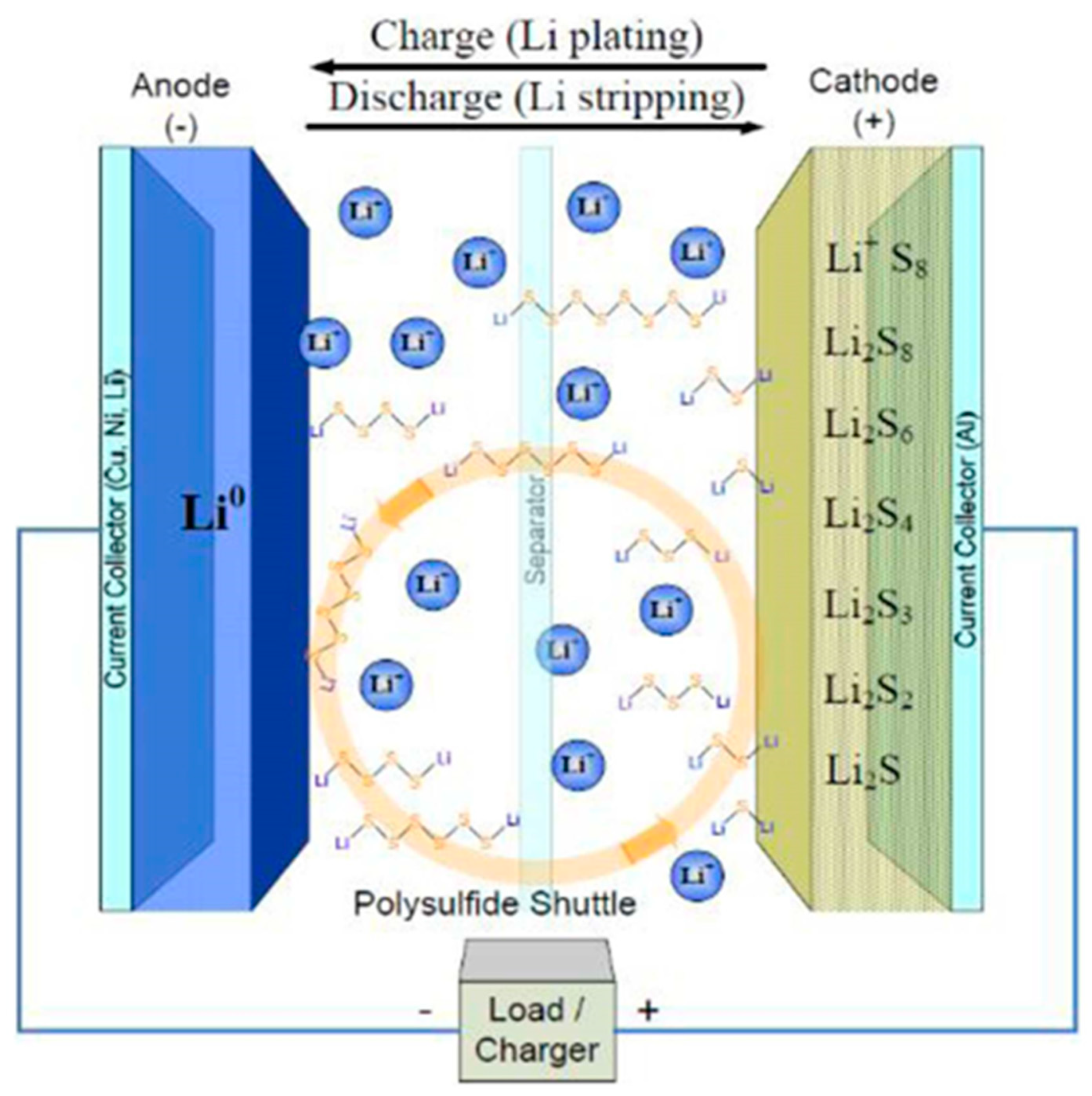
Figure 2.
A ordinary charge/discharge profile curves for LSBs9.
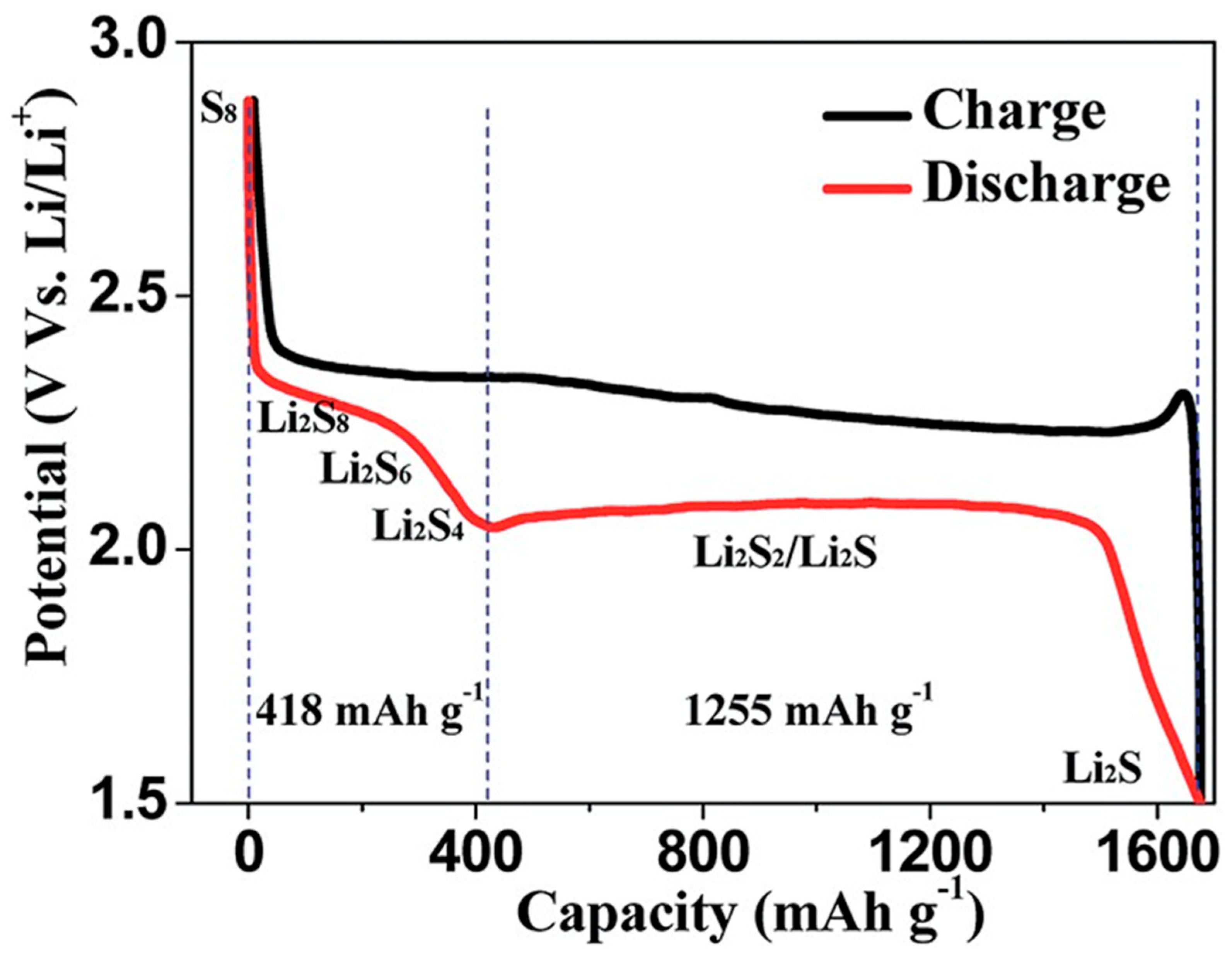
Figure 3.
36SEM photograph of the surface of.(a) bare lithium (b) Ag co-deposited lithium. Cross-sectional SEM images of (c) bare lithium (d) Ag co-deposited lithium. Symmetric LSBs are discharged at a current density of 2.5 mA cm-2.
Figure 3.
36SEM photograph of the surface of.(a) bare lithium (b) Ag co-deposited lithium. Cross-sectional SEM images of (c) bare lithium (d) Ag co-deposited lithium. Symmetric LSBs are discharged at a current density of 2.5 mA cm-2.
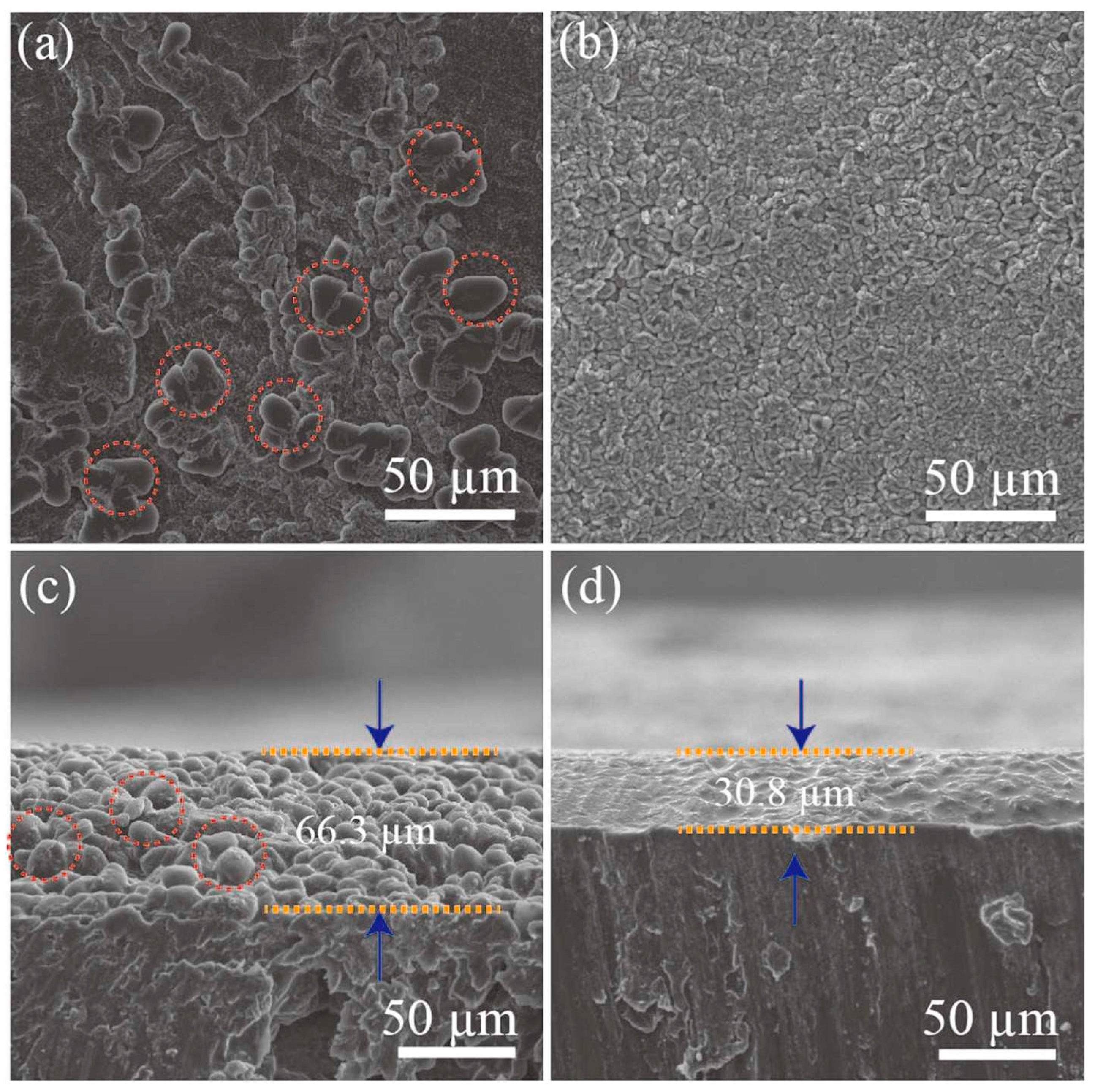
Figure 4.
37A) Speculated image of the BN-carbon separator role in the discharging process. (B) BN-coated separator picture (C) Twisted BN-coated separator picture image. Scheme 250. cycles using different separators. (I) Cycle performances of various kinds of separators at 0.5 C.
Figure 4.
37A) Speculated image of the BN-carbon separator role in the discharging process. (B) BN-coated separator picture (C) Twisted BN-coated separator picture image. Scheme 250. cycles using different separators. (I) Cycle performances of various kinds of separators at 0.5 C.
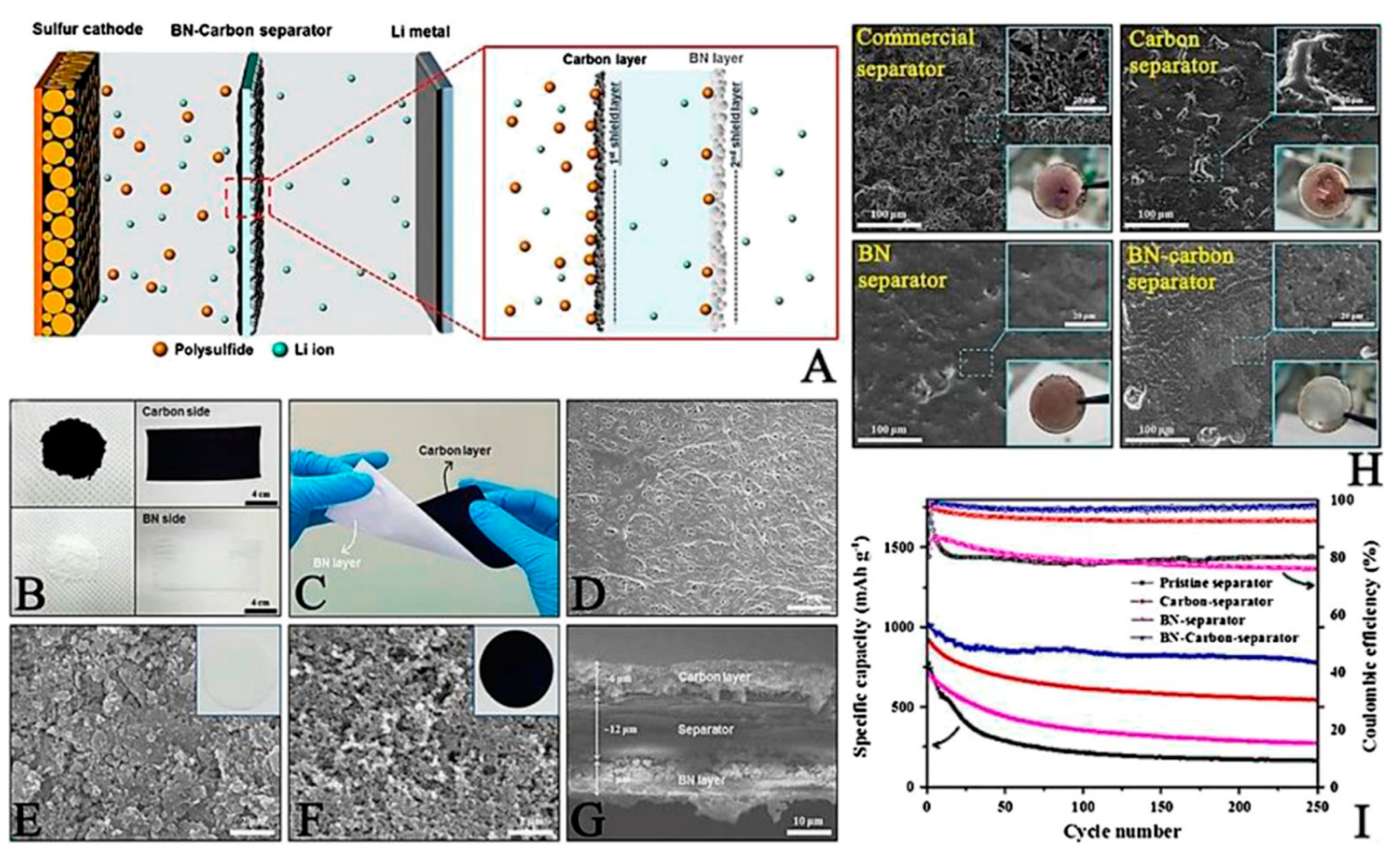
Figure 5.
46. (a) The schematic illustration of coating a PPy ultrathin nanolayer on both surfaces of the separator using a facile vapor-phase polymerization process. (b) Digital photos of the Celgard separator without and with PPy modification. Top-view SEM pictures of a Celgard separator (c) without and (d) with PPy modification. The size of the nanopores of the separator was reduced after PPy modification. (e) Comparison of the thickness and weight of functional coating on the Celgard separator in this work with those reported in the literature. (f) XPS spectra of a Celgard separator without and with PPy modification. The signal of N arises from the PPy modification layer. (g) High -resolution N 1s spectrum of the PPy modified separator. .
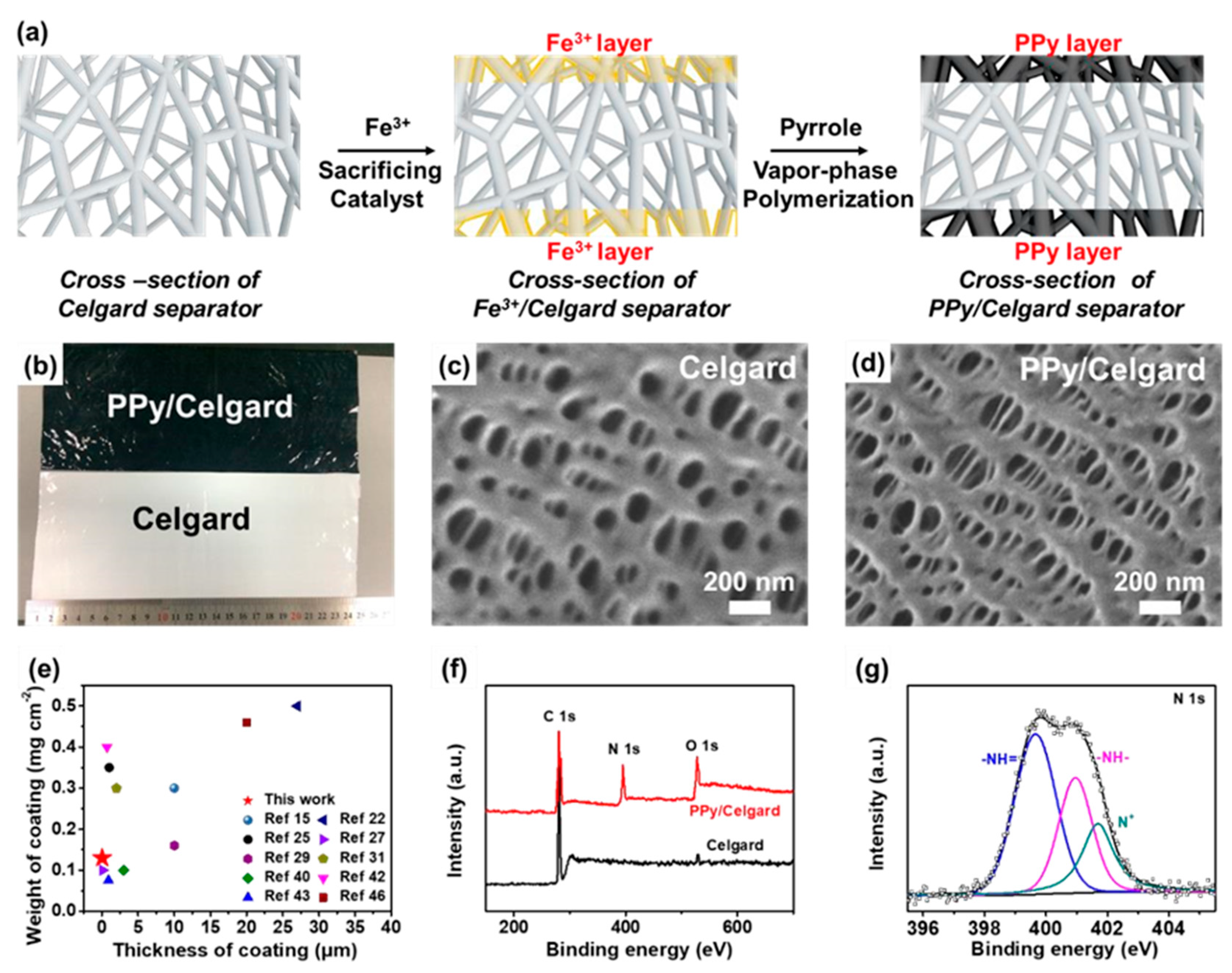
Figure 6.
Classification and Functional Mechanism of functional separators in LSBs31.
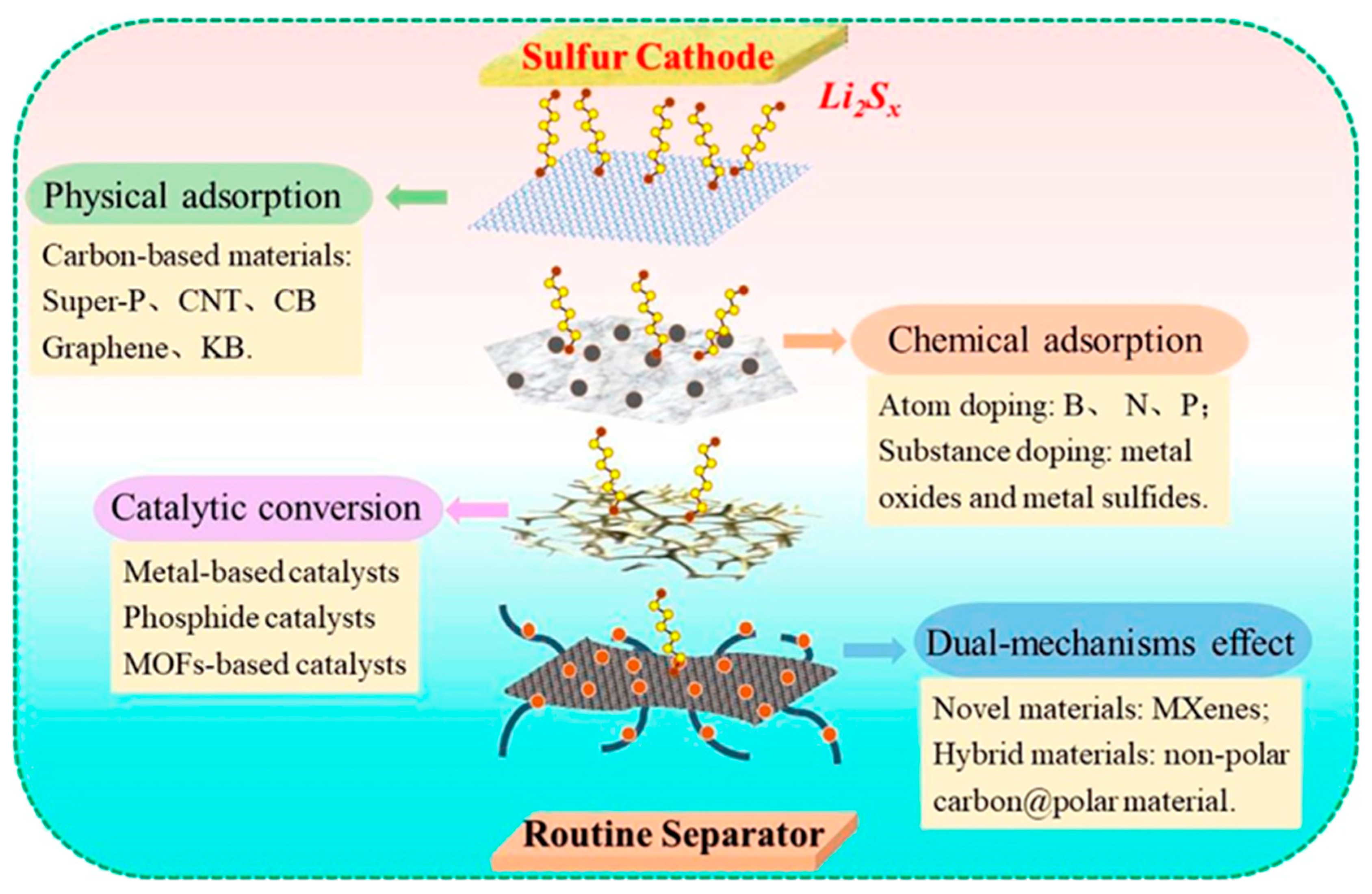
Figure 7.
Schematic image of LiPS capture by the CNTOH-coated separator57. (a) The soluble LiPS transport through the PE separator to the anode side, resulting in low sulfur usage. (b) In case of the CNTOH-coated separator, the soluble LiPS are captured by the hydroxyl functional groups and reused to form short-chain polysulfides. (c) Surface modification of CNT by applying hydrothermal method to create CNTOH.
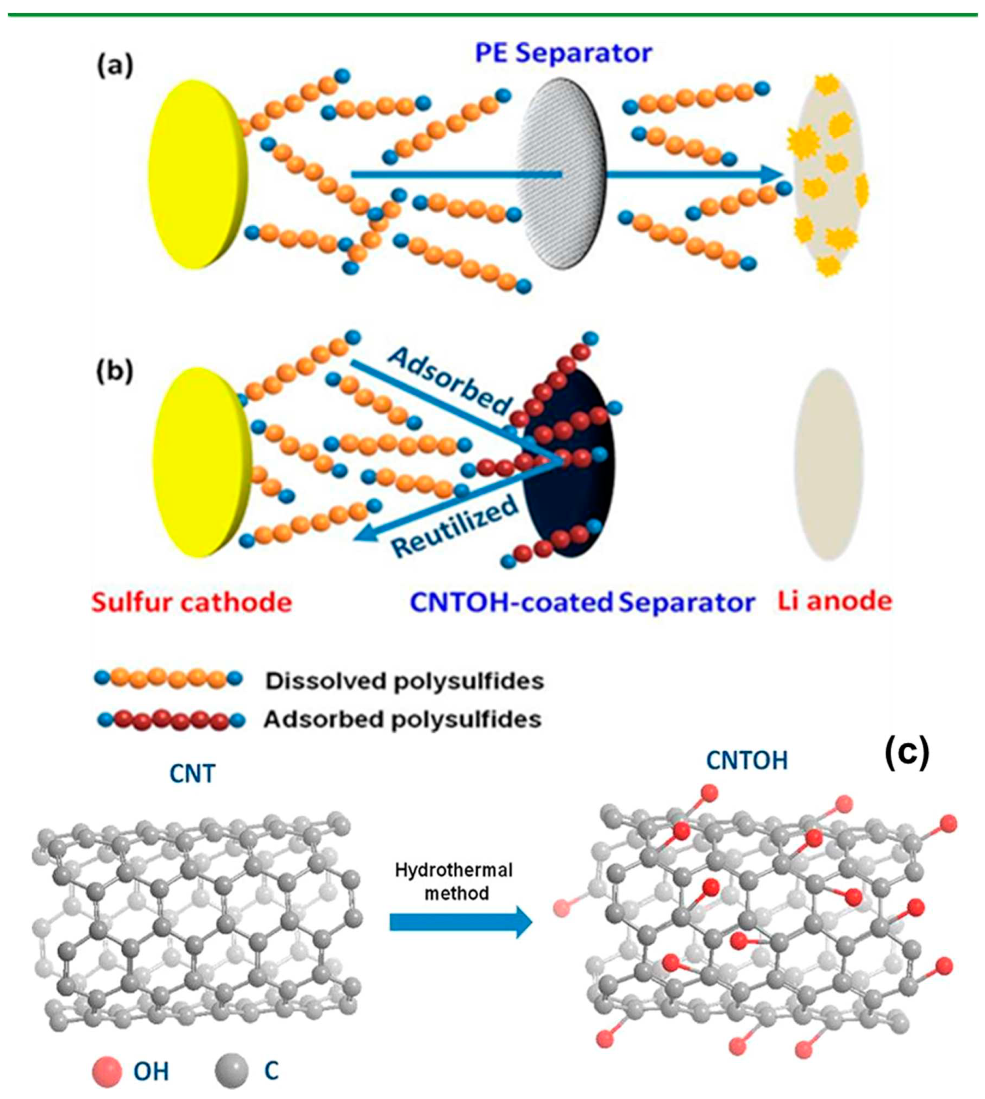
Figure 8.
Synthesis and Morphology of the rGO/SL Composite and Preparation of rGO/SL/PP Separator63.(A) Molecular structure and synthetic steps to produce rGO/SL. (B) FTIR spectra of GO, SL, and rGO/SL. (C) Scanning EM images of the rGO/SL composite. (D) HRTEM images of the rGO/SL composite. (E) Elemental mapping images of C, N, and S in a selected region of rGO/SL. (F) Fabrication procedure for the rGO/SL/PP separator. (G) Scanning EM image of the multilayered rGO/SL/PP separator. (H) Pictures of the rGO/SL/PP separator against various kinds of mechanical stresses. (I) Schematic illustration of the rGO/SL/PP separators for suppressing LiPS shuttling effect in LSB.
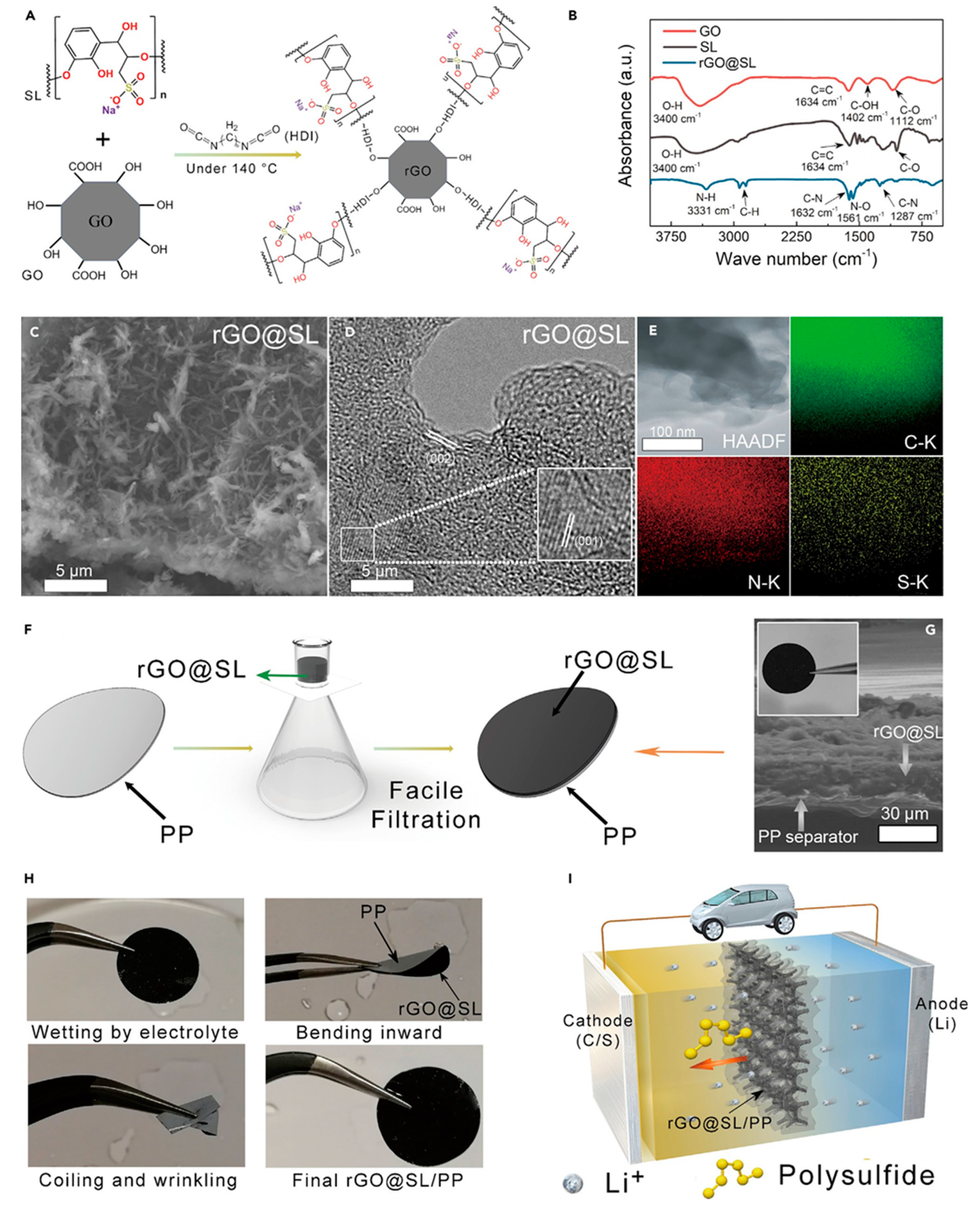
Figure 9.
65 a) The adsorption-desorption isotherms of N2 (b) BJH pore-size distribution curves of the CNS/N-rGO composite and CNS/N-rGO/S.(c) XRD pattern of the CNS/N-rGO composite (d) Raman spectrum of the CNS/N-rGO composite.
Figure 9.
65 a) The adsorption-desorption isotherms of N2 (b) BJH pore-size distribution curves of the CNS/N-rGO composite and CNS/N-rGO/S.(c) XRD pattern of the CNS/N-rGO composite (d) Raman spectrum of the CNS/N-rGO composite.
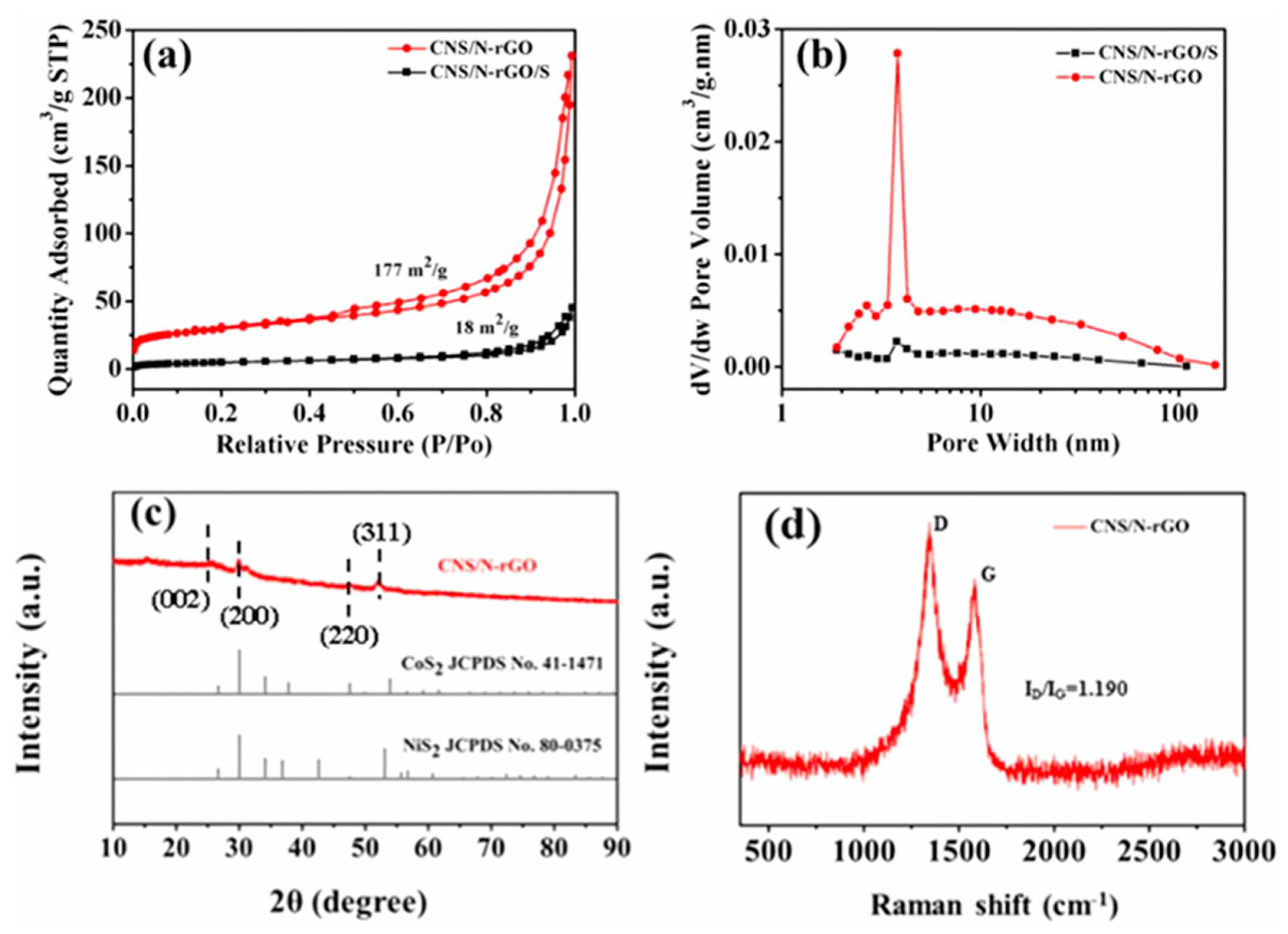
Figure 10.
Schematic model of the operation and preparation of the Edge-MoS2/C/PP separators in LSB81. a. Image illustration of polysulfides capture in LSB with Edge-MoS2/C/PP separator. b. Image illustration of Li2S deposition on the separator with edge-MoS2/C/PP and PP. c. Synthesis procedure of the Edge-MoS2/C hollow microspheres and illustration of the edge and terrace sites of the Edg-MoS2/C hollow microspheres.
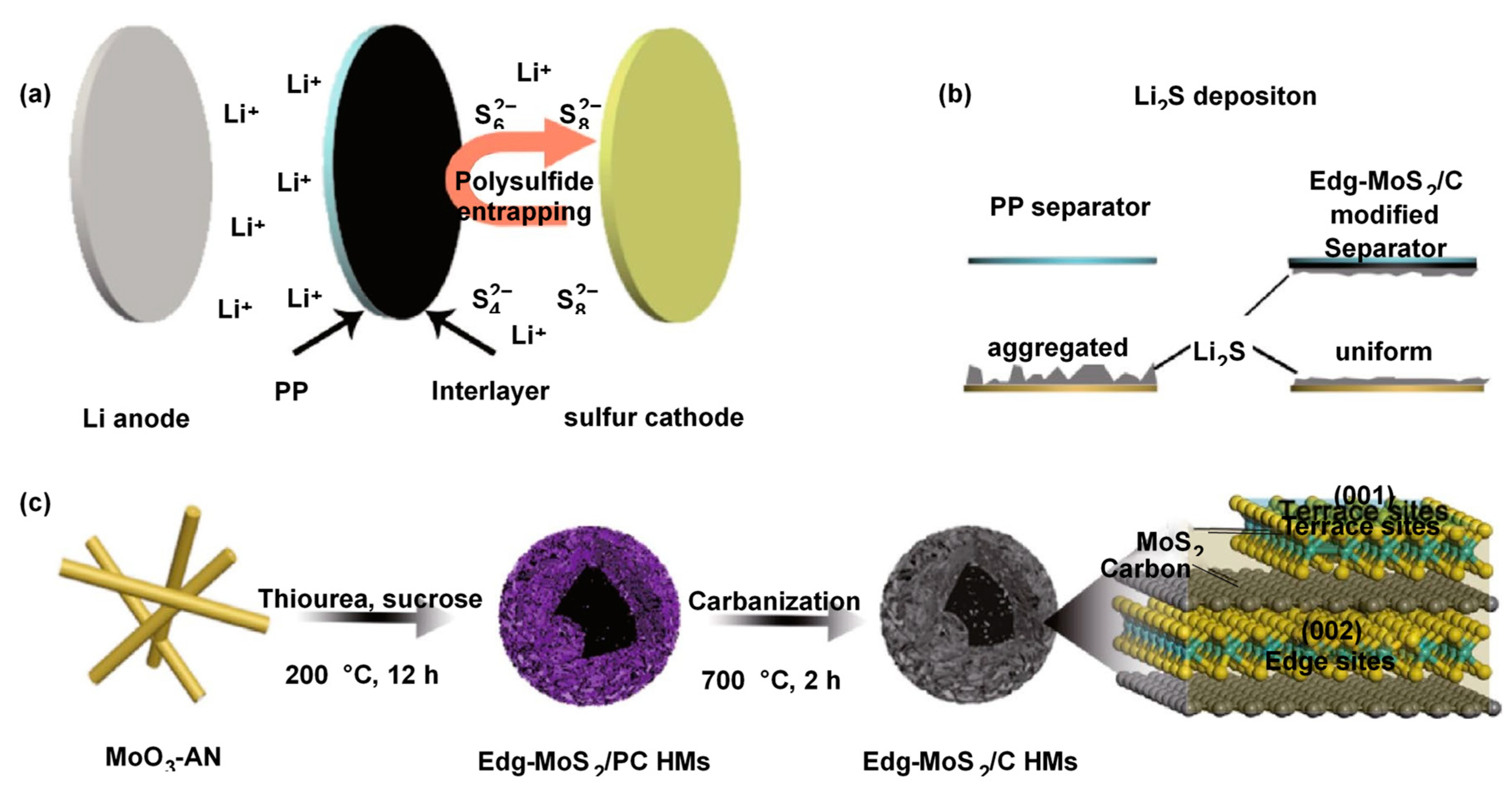
Figure 11.
The pictures of the LiPS capture (adsorption) experiment: (A) Before (B) After rest for 2 hours (C) Photographs of the of the TiC nanoparticles coated separator and its bent image88.
Figure 11.
The pictures of the LiPS capture (adsorption) experiment: (A) Before (B) After rest for 2 hours (C) Photographs of the of the TiC nanoparticles coated separator and its bent image88.
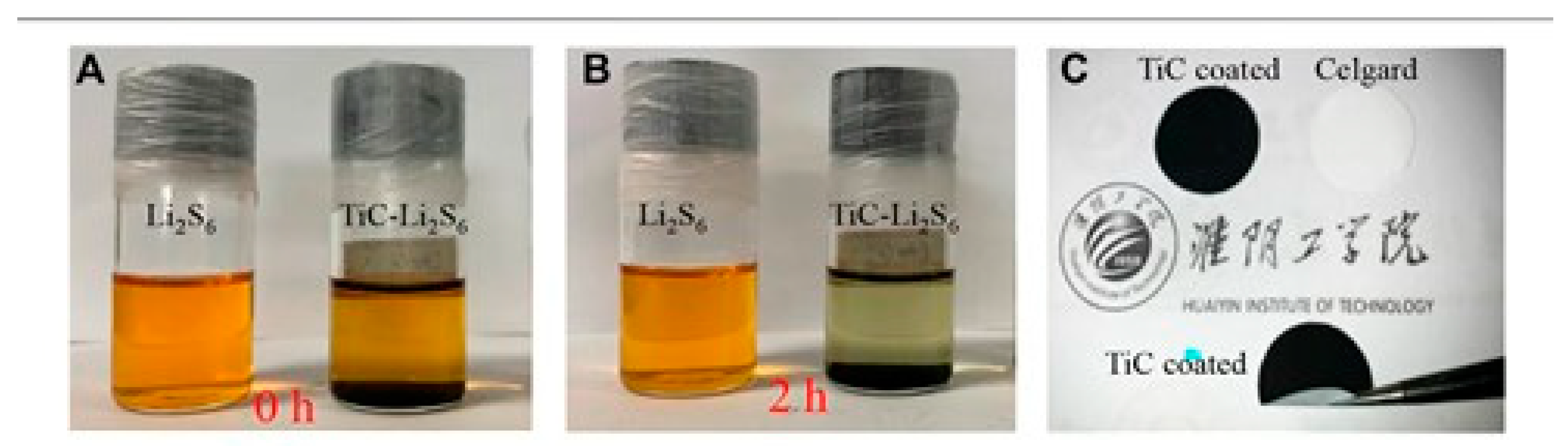
Figure 12.
97Lithium stripping/plating experiments with PP, BNNT, and p-BNNT loaded separator at (a) 0.35 mA/cm2 and (b) 1 mA/cm2.SEM images of lithium metal after finishing lithium stripping/plating measurement using (c) PP (d) BNNT-PP-0.5 and (e) p-BNNT-PP-0.5.
Figure 12.
97Lithium stripping/plating experiments with PP, BNNT, and p-BNNT loaded separator at (a) 0.35 mA/cm2 and (b) 1 mA/cm2.SEM images of lithium metal after finishing lithium stripping/plating measurement using (c) PP (d) BNNT-PP-0.5 and (e) p-BNNT-PP-0.5.
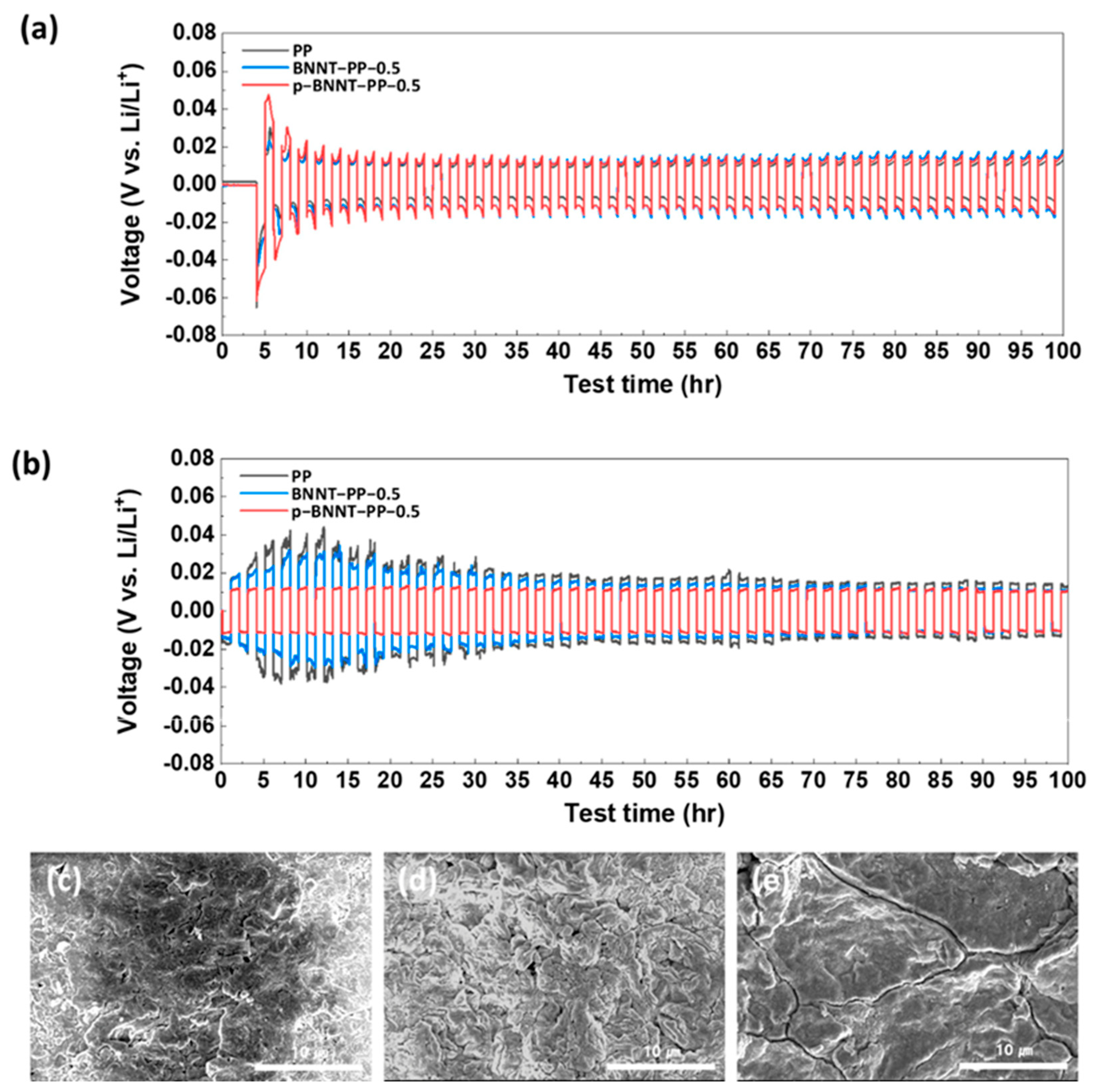
Figure 13.
105-107. (a) Cyclic voltammetry (b) Rate performances of LSB prepared with Ni/Ni2P-MCN/PP, Ni-MCN/PP, MCN/PP and pristine PP(c) Charge-discharge profiles of LSB prepared with Ni/Ni2P-MCN/PP at various current densities from 0.1 to 5 C. (d, e) LSB cyclic performance prepared with Ni/Ni2P-MCN/PP, MCN/PP and pristine PP at 0.2 and 0.5 C. (f) LSB cycling performance prepared with Ni/Ni2P-MCN/PP at 0.2 C with a high sulfur loading of 4.2 mg cm−2(g) LSB cycling performance prepared with Ni/Ni2P-MCN/PP, MCN/PP and pristine PP at 1 C.
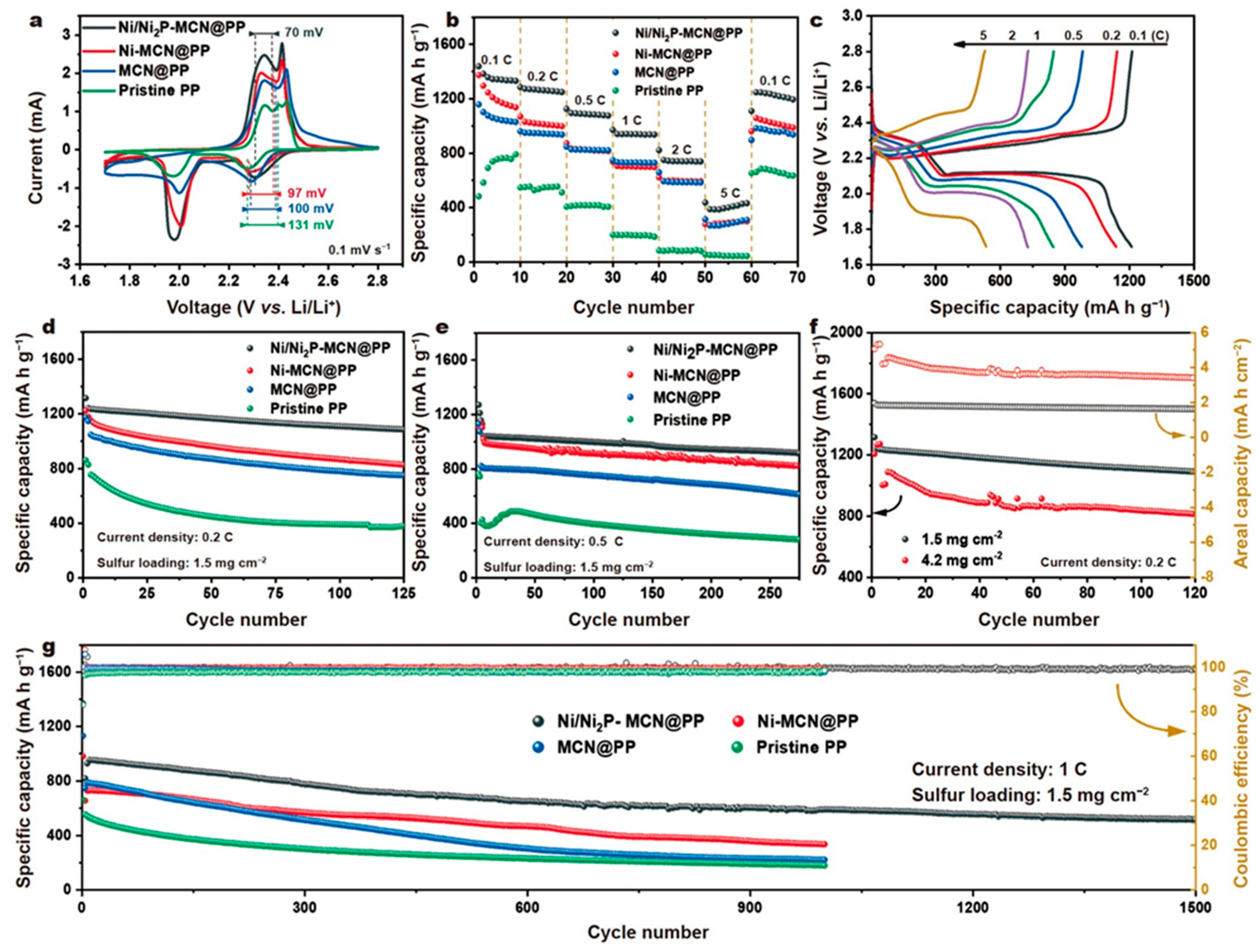
Figure 14.
Preparation and material characteristics of MOF/GO separators112. a. Illustration of preparation process to make MOF/GO separators. The MOF nanoparticles and GO laminates are interacted to compose a MOF/GO separator. b. Schematic image of the microporous crystalline structures (HKUST-1). The homogeneous coordinated structures are depicted as bars. The pores are displayed in a space-filling depiction. c. PXRD patterns of MOF/GO separators. The MOF structure remains unbroken after the discharge/charge process. d. SEM photographs of the multilayered MOF/GO separator. The inset presents a digital image from MOF side aspect. e. SEM photograph of the GO layer. The inset shows a digital image from the GO side aspect.
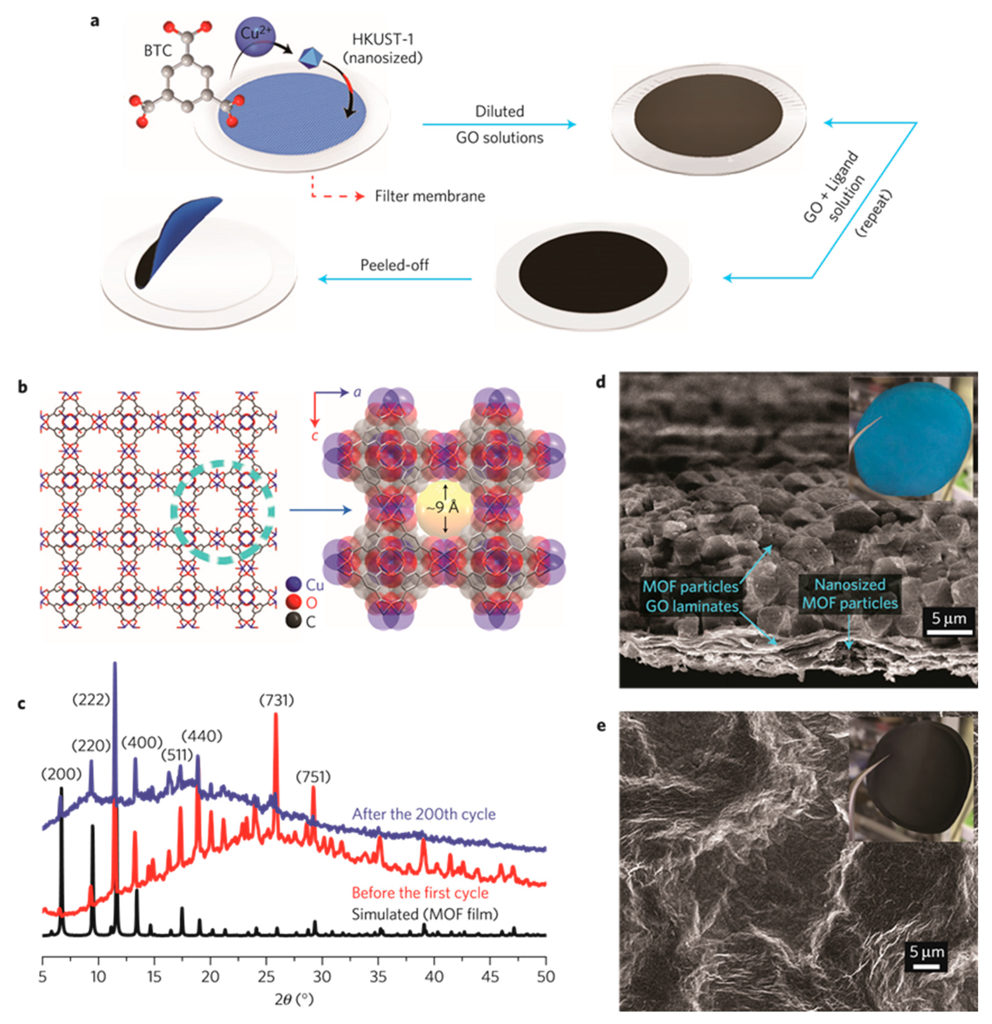
Figure 15.
119-122 (a) Speculated image of the synthesis procedure of MWCNTs/TiO2 quantum dots and LSB with conventional PP diaphragm and MWCNTs/TiO2 quantum dot coated diaphragm. (b) Long-term cycle tests of LSB prepared with Celgard, MWCNTs/Celgard and MWCNTs/TiO2 quantum dots /Celgard. (c) Speculated image of MWCNTs/NCQDs composite and HRTEM picture of NCQDs anchored on MWCNTs surface. (d) SEM image of MWCNTs/NCQDs-coated separator and cross-section of MWCNTs/NCQDs coated separator (e) Long-term cycle test at 1 and 2 C of the LSB with MWCNTs/NCQDs-coated separator. (f) Lithium plate picture after plating/stripping with MQD/NG/PP separators for 200 cycles. SEM image of the lithium plate with MQD/NG/PP separator and cross-section of the lithium plate after cycles (g) Cycle performance of LSB prepared with PP, G/PP, MQD/NG/PP at 0.2c.
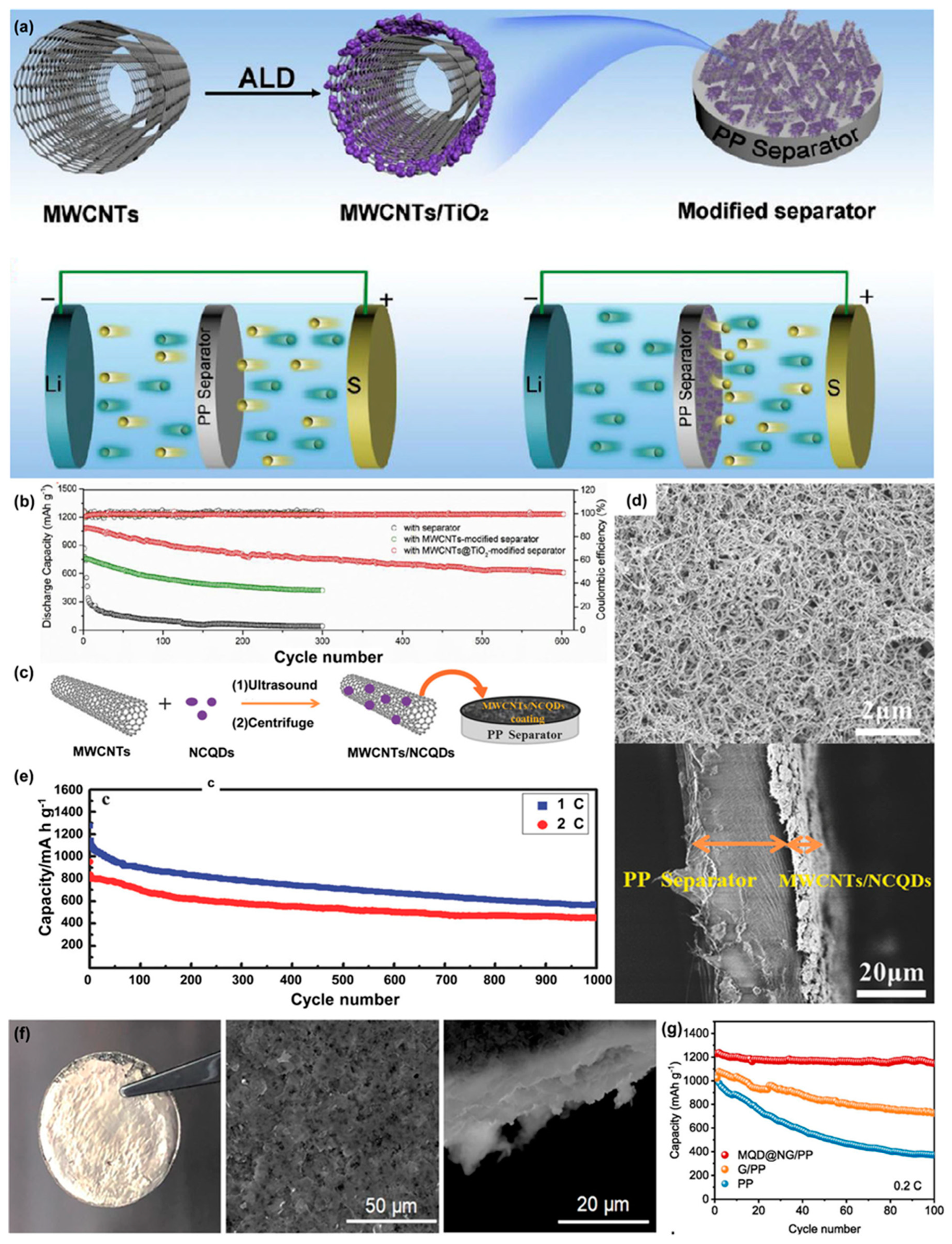
Figure 16.
137,138 (a) Schematic illustration of the electrode with a GF or GF/Ti3C2 separator1. (b) Cycling performance and coulombic efficiency at 0.5 A g–1. (c) Speculated image of the LiPS capture and process on TiO2-Ti3C2Tx heterostructures. (d) Cycling performance of LSBs with a Ti3C2Tx-GN interlayer with different sulfur loadings.
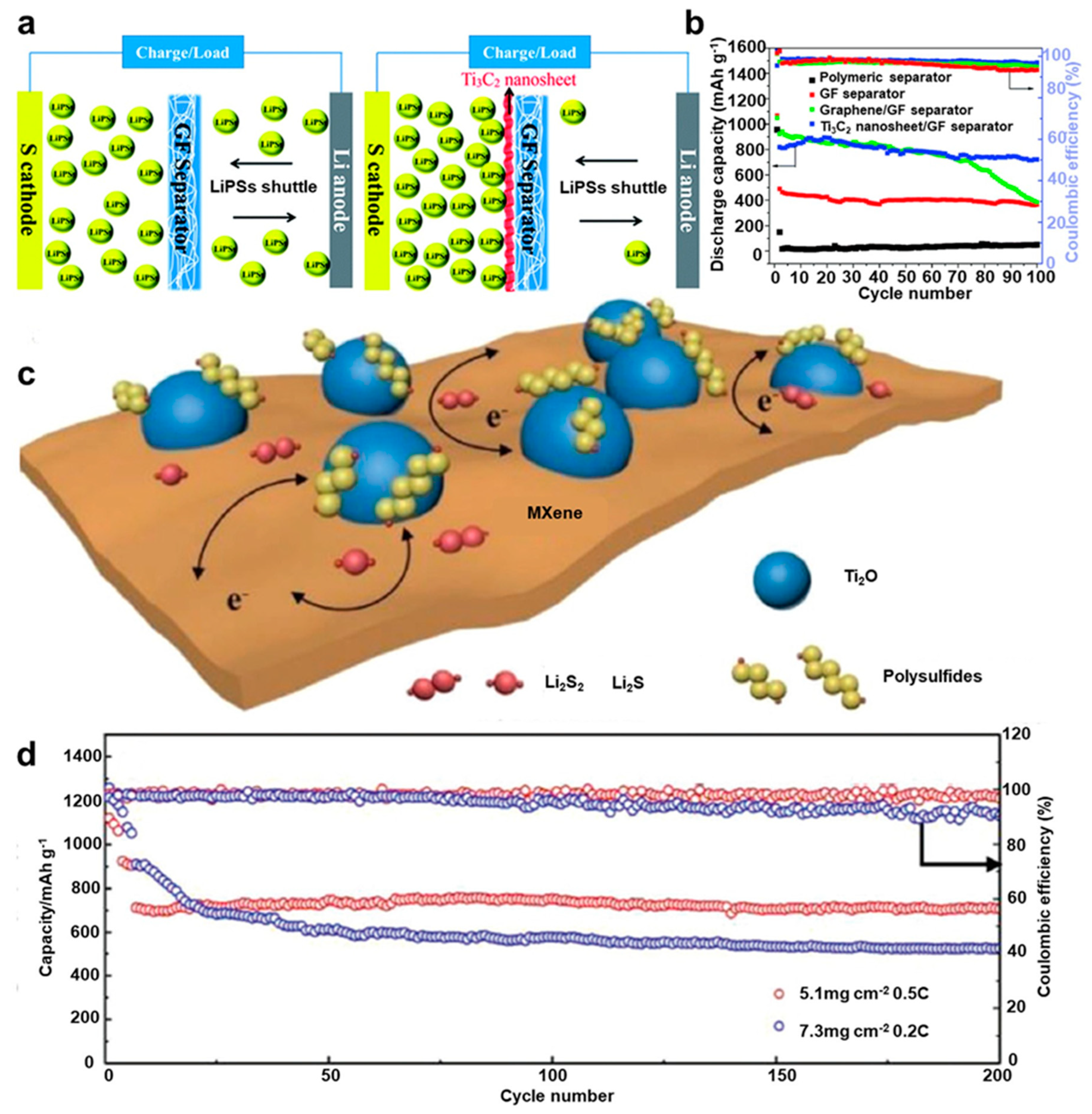
Figure 17.
Morphology of the surface of separators prepared from water dispersion146 a) containing NFC (nano fibrillated cellulose) fiber, paraffin oil, and surfactant b) containing only NFC fibers.
Figure 17.
Morphology of the surface of separators prepared from water dispersion146 a) containing NFC (nano fibrillated cellulose) fiber, paraffin oil, and surfactant b) containing only NFC fibers.
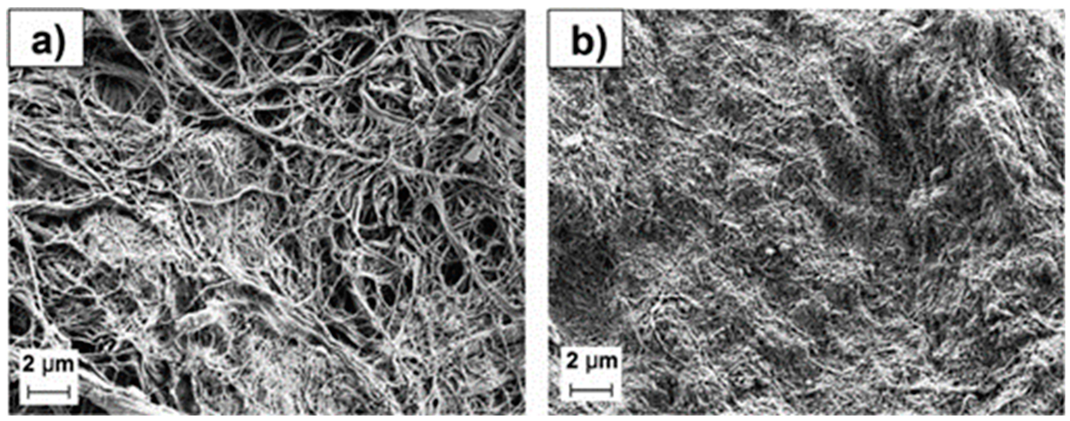

Table 1.
Comparative performances of LSB with various type of materials on separator anode side.Table 2. Comparative performances of LSB with various type of materials on separator anode side.
Table 1.
Comparative performances of LSB with various type of materials on separator anode side.Table 2. Comparative performances of LSB with various type of materials on separator anode side.
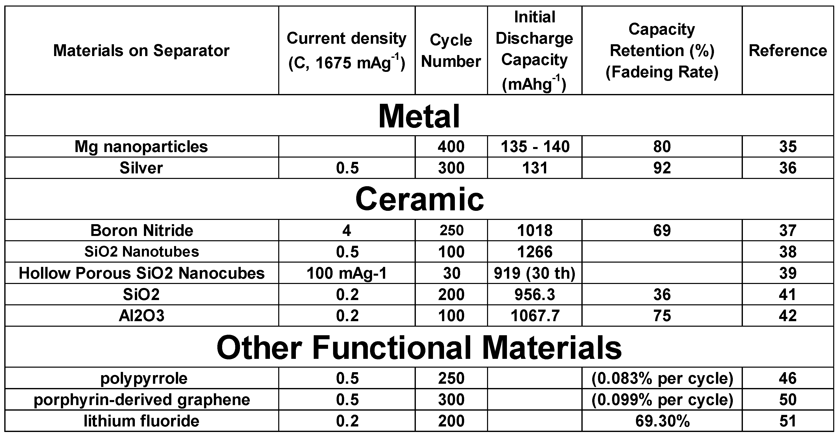 |
Table 2.
Comparative performances of LSB with various type of materials on separator anode side.
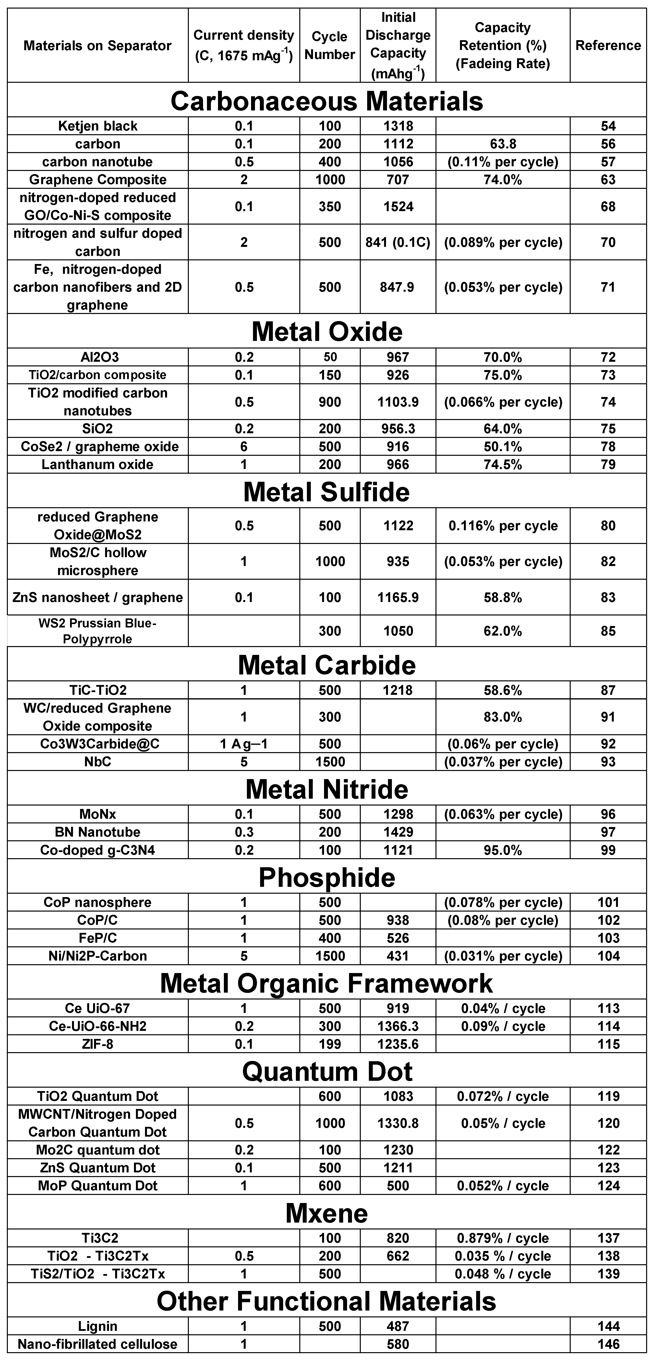 |
Disclaimer/Publisher’s Note: The statements, opinions and data contained in all publications are solely those of the individual author(s) and contributor(s) and not of MDPI and/or the editor(s). MDPI and/or the editor(s) disclaim responsibility for any injury to people or property resulting from any ideas, methods, instructions or products referred to in the content. |
© 2023 by the author. Licensee MDPI, Basel, Switzerland. This article is an open access article distributed under the terms and conditions of the Creative Commons Attribution (CC BY) license (https://creativecommons.org/licenses/by/4.0/).
Copyright: This open access article is published under a Creative Commons CC BY 4.0 license, which permit the free download, distribution, and reuse, provided that the author and preprint are cited in any reuse.


