
Submitted:
11 September 2023
Posted:
13 September 2023
You are already at the latest version
Abstract
The condensing heat exchanger is commonly applied in various heat exchange systems. It can efficiently recover moisture and heat from the flue gas that contains water vapor. However, the convective-condensation heat transfer process is so complicated that no mature thermal calculation model is available. This study develops a thermal calculation model for the widely employed tubular condensing heat exchanger in industry. To characterize the degree of the heat and mass transfer, this study introduces two parameters, namely the sensible and latent heat transfer efficiencies of fin. The thermal calculations are conducted for the condensing heat exchangers reported in the literature to verify the proposed model by comparing it with the experimental data. The results show that the absolute error of the calculated sensible and latent heat transfer efficiencies is 0.0365 and 0.0268, respectively. Under the working conditions in this study, a maximum difference of 5.2 K has been acquired between the measured and calculated values of the outlet temperature. The relative error of the condensate water flowrate is mostly within ±5.0% and ±10.0% under the bare-tube and finned-tube conditions, respectively, with a maximum deviation of 0.7 and 1.4 kg h-1. This study provides a general model for designing and optimizing various tubular condensing heat exchangers accurately.
Keywords:
Thermal calculation
; Convective-condensation heat transfer
; Tubular condensing heat exchanger
; Heat transfer
; Mass transfer
1. Introduction
The heat exchanger is a device that transfers heat from a high-temperature fluid to a low-temperature one [1]. The tubular heat exchanger, a kind of wall-type heat exchanger, is widely applied in the fields of chemical [2], power [3], food [4], etc. It can be classified as a condensing or non-condensing heat exchanger, depending on whether the condensation occurs or not. Condensation is a common phenomenon that happens in nature and human life. The water vapor condensation mainly includes the convective-condensation of the pure steam [5], the water vapor with a little non-condensable gas (NCG) [6], the high-moisture flue gas [7], and so on.
The logarithmic mean temperature difference (LMTD) is a crucial concept during the design of the heat exchanger. The LMTD method could be successfully employed only if two assumptions could be met: (1) the specific heat capacity and the mass flow rate of the hot and cold fluids are kept constant, and (2) the heat transfer coefficient is kept constant. Fortunately, both of the two assumptions are fulfilled during the convective-condensation process of the pure steam or the water vapor with a little NCG [8,9,10].
During the convective-condensation process of the high-moisture flue gas, the heat and mass transfer occur at the same time [11]. The flue gas parameters, such as the composition, the specific heat capacity, the convective heat transfer coefficient, etc., along the flow direction would vary considerably, resulting in a heat transfer process of great complexity. Therefore, the LMTD method is not applicable to solve the temperature difference between the hot and cold fluids. Meanwhile, it is difficult to calculate the average convective-condensation coefficient of the entire heat transfer surfaces. It is even harder to obtain the heat and mass transfer of the flue gas simultaneously only through the heat transfer calculation.
A series of previous studies [12,13,14,15,16] have applied the experimental methods to examine the process of the convective-condensation heat transfer in the high-moisture flue gas and to explore the design calculation method of the condensing the heat exchanger. Zhao et al. [17] established a system to study the condensation heat transfer of the water vapor mixed with air. The experimental results indicated that the condensation performance decreases significantly with the increasing volume fraction of air. Based on the theories of heat and mass transfer, Krempaský et al. [18] proposed a condensation model of the water vapor with NCG. In their experimental verification, the mixture of water vapor and air flowed through a vertical tube, as the air proportion ranges from 0.230 to 0.620. The predicted and experimental results were in good agreement, with the standard deviation between -5 % and +25 %. Zhu et al. [19] studied the effects of different parameters on the heat and mass transfer in an elliptical tube. The empirical correlations of heat transfer coefficient were finally fitted by analyzing the experimental data, which presented an enough accuracy in engineering. Xu et al. [20] investigated the convective-condensation of the humid gas in a horizontal tube. The heat transfer performances of the corrugated and spiral tubes were compared to the bare tube. The heat transfer coefficient of the two intensified tubes increased by 47.13% and 116.04%, respectively. Poredoš et al. [21] evaluated the condensation heat transfer of the humid air inside vertical channels theoretically and experimentally. A new semi-empirical correlation was developed in the theoretical part, with the applicable range of air mass fraction extending to 0.683–0.974. The correlation was verified experimentally, with 90% of the calculated values having relative errors within ±12% of the measured values.
Many other studies [9,22,23] have utilized the LMTD method to determine the convective-condensation heat transfer coefficient on the flue gas side based on the experimental data. However, it is not appropriate to apply this method for calculating the thermodynamic parameters of the high-moisture flue gas during the convective-condensation process. Moreover, the convective-condensation heat transfer coefficient over the surface of the heat exchanger is distributed unevenly.
Numerical simulation has several advantages over experimental studies. For example, the condensing heat exchanger could be modeled in a 1:1 scale and studied numerically with the low investment. Therefore, a number of studies [24-26] have applied numerical methods to investigate the convective-condensation heat transfer of the flue gas. Morales-Fuentes et al. [27] numerically simulated the process of the saturated air flowing through different finned-tube surfaces. They found that the pin finned-tube showed a higher condensation rate than the annular and plain finned-tubes. Guo et al. [28] developed a numerical method to study the condensation of a plate evaporative cooler. The model was capable of predicting the state of condensation and calculating the ratio of condensation area. Alshehri et al. [29] presented a numerical model to simulate the process of water vapor condensation in the presence of NCG. The state parameters of condensate film and diffusion layer were calculated and then coupled by the condensation interface. Dehbi [30] highlighted the limitations of replacing the condensation rate of tube with the flat plate equivalents by correction factors, especially for the low NCG fraction and the small tube diameter. The procedure was improved by introducing a correlation from the numerical results. To broke the limitations of grids refinement, Li et al. [31] presented an extended condensation model. The predicted values of the condensate water flowrate were close to the measured ones, with the greatest relative error of 5.5%. Considering the existence of NCG, Jiang et al. [32] established a model for the convective-condensation heat transfer calculation on the basis of the pure steam dropwise condensation. The simulation results indicated that the capacities of absorptive mass transfer and surface condensation determined the heat transfer performance coordinately.
Previous researchers have applied the numerical simulations to examine how various factors affect the convective-condensation heat transfer through the CFD models, which could guide the design of the condensing heat exchanger. However, there are few studies focusing on the water vapor condensation in the finned-tube type bundles and the heat transfer of the high-moisture flue gas. It is also challenging to develop a thermal calculation model based on the numerical simulations alone.
A few researchers, such as Jeong [33], realized the calculation of heat transfer and condensate water flowrate in the condensing heat exchanger by using the finite difference method. This method is more general and reflects the physical process of the convective-condensation heat transfer. However, it is a complicated process that takes a long time to complete. Moreover, for the finned-tube type bundles, this method could not offer a better reflection about the conditions of the water vapor condensation on the fin surface and the heat transfer of the flue gas.
To address these issues, this study proposes a new thermal calculation model for the widely used tubular condensing heat exchanger theoretically. The sensible and latent heat transfer efficiencies of fin are determined to characterize the degree of the heat and mass transfer. The experimental results in the study of Jeong [33] are introduced to verify the proposed model.
2. Thermal calculation model for tubular condensing heat exchanger
2.1. Principle of thermal calculation
Taking a low-temperature heat tube in the condensing heat exchanger as an example, the convective-condensation heat transfer process of the high-moisture flue gas is illustrated in Figure 1. When the wall temperature drops below the dew point of the flue gas, a condensate film occurs on the tube surface due to the water vapor condensation [34,35]. The water vapor on the tube wall is condensed into droplets [36], causing a decrease in both the volume fraction and partial pressure of the water vapor. On the other hand, NCG accumulates in the low-temperature tube wall, leading to an increase in its volume fraction and concentration. Finally a boundary layer of NCG forms near the condensing wall, which would bring the primary resistance for the mass transfer of water vapor in the flue gas [37,38].
Assuming that the mean temperatures of the condensate film surface and the flue gas are and , respectively, the partial pressure of the water vapor of the two positions mentioned above is and , separately. Then the temperature difference and pressure difference offer the driving force for the heat and mass transfer, respectively. The sensible heat transfers from the flue gas to the cooling water through tube wall when the water vapor does not condense. However, when the condensation of water vapor occurs, the sensible and latent heat need to pass through the condensate film and tube wall in turn.
A simple geometric schematic of the condensing heat exchanger investigated in this study is displayed in Figure 2. The tube rows that make up the heat exchanger are divided into transverse and longitudinal tube rows, which are perpendicular and parallel to the flow direction of the flue gas, respectively. Before preforming thermal calculation for the condensing heat exchanger, some assumptions are listed as follows.
- (1)
- The flow of flue gas in a condensing heat exchanger is one-dimensional, which means that parameters like the temperature of the flue gas and the volume fraction of the water vapor only change in the direction of the gas flow.
- (2)
- The convective heat transfer and convective mass transfer coefficients of the flue gas are evenly distributed on the outer wall of each tube.
- (3)
- The inlet and outlet parameters such as the flue gas temperature, the volume fraction of the water vapor and the cooling water temperature are linearly changed for each transverse tube bundle, allowing for the calculated values of working fluid parameters in each bundle to be obtained through the arithmetic mean of these parameters.
- (4)
- The flow on the flue gas side is single-phase and any effect of liquid condensate on the flow is ignored.
- (5)
- Water vapor in the flue gas only condenses on the tube wall, not in the flue gas stream.
- (6)
- The thickness of condensate film is considered to be zero and the heat and mass transfer resistance of this film is ignored.
- (7)
- Secondary evaporation of the condensate water in the heat exchanger is also neglected.
- (8)
- No chemical reaction occurs in the condensing heat exchanger.
Based on these assumptions, a thermal calculation model for the tubular condensing heat exchangers is proposed in this study. The main calculation principles are as follows:
- (1)
- Firstly, the entire heat exchanger is divided into several tube bundles, with each transverse tube bundle being considered a heat exchanger unit. These units are connected in series to form the complete condensing heat exchanger.
- (2)
- Next, the thermal calculation is conducted on each individual heat exchanger unit. The heat transfer from the flue gas to the cooling water is divided into three processes, including the convective-condensation heat transfer of the flue gas on the outer wall of tube, the heat conduction of the tube wall, and the convective heat release from the inner wall to the cooling water inside the tube. The most complex process is the first one. To solve this, the sensible heat is calculated by the classical heat transfer formula [39]. The temperature difference for sensible heat transfer is equal to the difference between the arithmetic mean temperature of the incoming and outgoing flue gas and the temperature of the outer wall of tube. When the outer wall is under wet conditions, the latent heat transferred from the flue gas to the outer wall of tube is equal to the latent heat of vaporization released. The amount of the condensate water flowrate could be calculated by the classical mass transfer formula [39]. The mass concentration difference of the water vapor for the mass transfer is equal to the difference between the arithmetic mean mass concentration of the incoming and outgoing flue gas and the mass concentration on the outer wall of tube. However, the condensate water flowrate is zero when the outer wall is under dry conditions.
- (3)
- Finally, the thermal calculation is constructed for each heat exchanger unit in turn along the flow direction of the flue gas. The inlet parameters of the working fluid for the present heat exchanger unit are equal to the outlet parameters of the previous one. The iterative algorithm is applied for each heat exchanger unit and then the thermal calculation of the entire condensing heat exchanger could be completed.
2.2. Thermal calculation for each heat transfer unit
2.2.1. Sensible heat transfer
For the ith heat transfer unit, the sensible heat of the flue gas for the bare-tube type bundle is calculated by:
where is the convective exothermic coefficient from the flue gas to the outer wall of tube, (W m-2 K-1). is the area of the outer wall of tube, (m2). and are the average temperature of the flue gas and the outer wall of tube, respectively, (K).
For the finned-tube type bundle, the sensible heat of flue gas is determined as:
where is the area of tubes not occupied by fins, is the area of fins, (m2).
Additionally, the in Equation (2) is a parameter called the sensible heat transfer efficiency of fin introduced in this study. The purpose is to characterize the effective degree of sensible heat transfer on the fin surface under wet conditions. It is defined as:
When the fins are under dry conditions, the total heat transfer on their surface is the same as the sensible heat transfer of the flue gas. This means that the sensible heat transfer efficiency of fin is equal to the fin efficiency, which can be obtained by the standard method [40].
2.2.2. Condensate water flowrate and latent heat transfer
For the ith heat transfer unit, the condensate water flowrate is zero under dry conditions. While for the bare-tube type bundle under wet conditions, it is calculated as:
where is the convective mass transfer coefficient of the flue gas, (m s-1). and are the average water vapor mass concentrations of the flue gas and the surface of the base-tube, respectively, (kg m-3).
For the finned-tube type bundle, the condensate water flowrate is determined as:
Aiming at characterizing the effective degree of the condensation mass transfer on the fin surface under wet conditions, this study introduces a parameter called the latent heat transfer efficiency of fin in Equation (5). It is described by:
After calculating the condensate water flowrate, the latent heat could be obtained by:
where is the latent heat of vaporization for water vapor, (kJ kg-1).
2.2.3. Energy balance on the flue gas side
The enthalpy difference between the inlet and outlet flue gas in the ith heat transfer unit is equal to the sum of the sensible and latent heat transfer of the flue gas, which can be described as:
where and are the enthalpies of inlet and outlet flue gas, respectively, (kJ kg-1).
2.2.4. Energy balance on the water side
The heat absorbed by the cooling water is equal to the heat released by the inner wall of tube.
where is the constant-pressure specific heat capacity of the cooling water, (kJ kg-1 K-1), is the convective heat transfer coefficient of the cooling water, (W m-2 K-1).
2.2.5. Total energy balance
The principle of energy conservation shows that the amount of heat released by the flue gas is equal to the amount of heat absorbed by the cooling water, which is also equal to amount of the heat conducted through the tube wall. This leads to the establishment of a total energy balance equation:
2.2.6. Heat conduction of the tube wall
The connection between the temperature of the inner and outer walls of tube can be established through the thermal conductivity equation. Then the temperature of the inner and outer walls of tube could be connected as:
where is the tube thickness, (m), is the fouling resistance, (m2 K W-1).
2.3. Sensible and latent heat transfer efficiencies of fin
The temperature distribution on the fin surface is significantly complicated under the wet conditions. Sharqawy et al. [41,42,43] studied the fin efficiency and the fin surface temperature distribution under the wet conditions. They defined the fin efficiency as:
where is the greatest heat transfer assuming the fin surface temperature is equal to the fin-root temperature, (W).
Sharqawy et al. [41-43] did not differentiate between the sensible and latent heat efficiencies of fin in their study. However, it is clear from their results that when the condensation of the water vapor occurs on the fin surface, the main factors affecting the sensible and latent heat transfer efficiencies are, the ratio of the fin outer diameter to the tube outer diameter Dfin/d, the fin thickness δfin, the fin height hfin, the fin thermal conductivity λfin, the convective heat transfer coefficient of the flue gas hfg (or the convective mass transfer coefficient ), the flue gas temperature Tfg, the volume fraction of the water vapor ωv, the flue gas pressure Pfg and the temperature of the outer wall of base-tube Tow (the fin-root temperature). Then the fin efficiency can be written as:
To facilitate the engineering calculations, eight of the nine influencing factors mentioned above would be converted into two dimensionless parameters and by the method of magnitude analysis. Finally, , and are employed as the independent variables to obtain the formulae for the sensible and latent heat transfer efficiencies of fin.
Similar to the dimensionless parameter defined in the standard method [40], this study defines the dimensionless criterion number that affects the heat and mass transfer performance of fin:
It can be seen that . With other parameters remaining the constant, the larger is, the higher the average temperature of fin surface is, the smaller the is, and the smaller the corresponding is.
By analyzing the effect law of each influencing factor on the sensible and latent heat transfer efficiencies, this study also defines the dimensionless number . Firstly, and are transformed into the water dew point of the flue gas, which has the following functional form:
Tdew = f(ωv,Pfg)
Then, the dimensionless number can be collapsed from Tfg, Tow
and :
It can be seen that , so . When , i.e., , the water vapor will not condense on the fin surface, indicating that the fins are under dry conditions. When , i.e., , the fins are under wet conditions. In this case, with other parameters remaining unchanged, the larger is, the greater the amount of water vapor condensation is, the higher the is, and the lower the is.
In summary, the fin efficiency could be expressed in the following functional form:
The numerical results of and under 324 groups of different wet conditions are collected through Fluent software [44]. Then the expressions of and are fitted as follows. In addition, for those 324 groups of data about the fin efficiency, the mean absolute errors between the calculated and numerically computed values of Equations (18) and (19) are 0.0365 and 0.0268, respectively.
2.4. Process of thermal calculation
3. Structure of condensing heat exchanger
In this study, the bare-tube and annular finned-tube heat exchangers reported in the literature [33] are chosen as the calculated objects. Three specific cases, named 0108BL, 0731BLa and 0718BL, listed in Table 1, are selected to verify the proposed model.
In Figure 4 (a), the bare-tube heat exchanger has the flue gas flowing through HX1, HX2, HX3, HX4 and HX5 sequentially. However, in the finned-tube heat exchanger shown in Figure (4) b, the flue gas flows through HX1, HX2, HX3 and HXFIN. HXFIN comprises the annular finned-tubes commonly used in engineering, whose structure is presented in Figure 4 (c). All the tube bundles are arranged in-line. The flue gas flushes the tube bundle transversely outside the tube, while the cooling water flows longitudinally inside the tube, demonstrating a countercurrent flow arrangement. The structural parameters of each sub-heat exchanger are provided in Table 2.
4. Case study
4.1. Bare-tube condensation model
The cases researched by Jeong [33] are applied in the verification of the proposed model. The comparisons of the experimentally measured and numerically calculated values of the flue gas temperature and the condensate water flowrate under the 0108BL condition are shown in Figure 5. As seen in Figure 5 (a), the relative heat transfer area, which is the ratio of the area through which the flue gas flows to the entire heat exchanger area, increases along the flow direction of the flue gas. Meanwhile, the measured and calculated values of the flue gas temperature decrease consistently. This is due to that the flue gas continually flushes the tube wall to release its heat [37]. The flue gas temperature reduces from 400.9 to 294.3 K during the heat transfer process. At the outlet of the condensing heat exchanger, both the measured and calculated temperatures of the flue gas are very close, with a difference of only 5.2 K and a relative error of 1.7%. In HX1 and HX2, the condensate water flowrate is zero, but a jump occurs in HX3 (as presented in Figure 5 (b)). This suggests that the flue gas temperature drops below the dew point in HX3 and consequently, the water vapor starts to condense [45]. Although a certain deviation happens in the condensate water flowrate between the measured and calculated values for each sub-heat exchanger, both the two follow a similar trend. For the entire exchanger, the absolute deviation of the condensate water flowrate is only 0.14 kg h-1 and the relative error is 1.82%.
Figure 6 displays a comparison of the flue gas temperature and the condensate water flowrate under the 0731BLa operating condition. The measured and predicted flue gas temperatures decrease in a consistent trend with the increasing relative heat transfer area, as demonstrated in Figure 6 (a). The flue gas temperature reduces from 421.5 to 299.8 K throughout the heat transfer process. The calculated temperature of the flue gas at the outlet of the condensing heat exchanger is extremely close to the measured one, with an error of only 1.3 K. In a similar fashion to the 0108BL case, the calculated condensate water flowrate in each sub-heat exchanger agrees well with the measured one, as presented in Figure 6 (b). The absolute deviation of the condensate water flowrate is 0.10 kg h-1 and the relative error is only 0.94% for the entire heat exchanger. However, the water vapor starts to condense before HX3 under the 0731BLa condition. This indicates that the convective-condensation heat transfer of the flue gas is more intense under this condition than under the 0108BL condition, which could also be proved by the steeper change curve of the flue gas temperature [46].
This study also utilizes the proposed thermal calculation model to determine the condensate water flowrate under the 0805T90a and 0814T100 operating conditions, as shown in Figure 7. The absolute deviation of the condensate water flowrate is 0.41 and 0.55 kg h-1 under the two conditions, respectively. The relative error of the predicted condensate water flowrate for each sub-heat exchanger is within ±20.0%, with the error for the entire heat exchanger being 4.9% and 8.4%, respectively. The trend matches well with the experimental data [47], demonstrating the accuracy of the condensation mass transfer model developed in this study.
Furthermore, the proposed model is used to conduct thermal calculations for various cases of the bare-tube condensing heat exchanger mentioned in the literature [33]. The comparisons of the condensate water flowrate between the calculated and measured values are exhibited in Table 3. Notably, the relative error of the condensate water flowrate falls mostly within ±5.0% across different studied conditions, with the highest deviation being 17.4%.
4.2. Finned-tube condensation model
The 0718BL operating condition is selected to check the accuracy of the proposed model for the finned-tube condensing heat exchanger. Figure 8 presents the comparisons of the experimental and calculated results of the flue gas temperature and the condensate water flowrate. The flue gas temperature drops from 418.5 to 307.0 K during the entire heat transfer process, as shown in Figure 8 (a). At the outlet of the heat exchanger, the deviation between the measured and calculated temperatures of flue gas is 3.3 K, with a relative error of only 1.1%. The proposed model correctly predicts the distribution of the condensate water flowrate, with the highest condensate water flowrate occuring in HX3, and the lowest occuring in HX1. The current findings are consistent with the experimental results in the previous study [33].
The proposed model is also applied to create thermal calculations for a number of other finned-tube cases mentioned in the literature [33]. Table 4 displays a comparison of the calculated and measured results for the condensate water flowrate. The results indicate that the relative error of the condensate water flowrate is mostly within ±10.0% in different studied cases, with the largest deviation being 19.4%.
5. Conclusions
This study establishes a thermal calculation model for the design of the tubular condensing heat exchanger. The experimental data reported in the literature is employed for the verification. Additionally, two parameters for characterizing the effective degree of the heat and mass transfer of annular fin, namely the sensible and latent heat transfer efficiencies are introduced and their formulae are fitted by the numerical results. The main conclusions are summarized as follows:
- (1)
- By using the thermal calculation model derived from theoretical analysis, it is possible to not only determine the sensible and latent heat transfer, as well as the condensate water flowrate, but also predict the distributions of the flue gas temperature and the water vapor volume fraction. Additionally, the location where the condensation of the water vapor begins could be determined by monitoring the condensate water flowrate of each sub-heat exchanger.
- (2)
- The sensible and latent heat transfer efficiencies for the annular fin are obtained by fitting the numerical data, with the absolute errors of 0.0365 and 0.0268, respectively.
- (3)
- Under the 0108BL and 0731BLa conditions with bare-tubes, the flue gas temperature decreases by 106.6 and 121.7 K, respectively. The outlet temperature of the flue gas has a deviation of 5.2 and 1.3 K, respectively. The water vapor starts to condense in HX3 under the 0108BL condition, which is later than the 0731BLa condition. The relative error of the condensate water flowrate is within ±5.0% under all 34 bare-tube conditions, with a maximum relative error of 17.4%.
- (4)
- The flue gas temperature decreases from 418.5 to 307.0 K under the finned-tube condition of 0718BL. In this case, the absolute deviation of the calculated outlet temperature of the flue gas is 3.3 K. The difference between the measured and simulated results of the condensate water flowrate is only 0.99 kg h-1. For the other 30 finned-tube conditions, the relative error of the condensate water flowrate mostly falls within ±10.0%, with the greatest deviation being 19.4%.
Author Contributions
Conceptualization, Lei Han, Kaixuan Yang, Ruiyu Li, Yuhang Li, Lei Deng and Defu Che; Data curation, Lei Han, Jiahui Yang and Lei Deng; Investigation, Lei Han, Jiahui Yang and Lei Deng; Resources, Yuhang Li; Supervision, Lei Deng and Defu Che; Writing – original draft, Lei Han, Jiahui Yang and Lei Deng; Writing – review & editing, Kaixuan Yang, Ruiyu Li, Yuhang Li and Defu Che.
Institutional Review Board Statement
Not applicable.
Informed Consent Statement
Not applicable.
Data Availability Statement
The data that support the findings of this study are available from the corresponding author upon reasonable request.
Acknowledgments
This work has been financially supported by Huaneng Group Science and Technology Project - Research and Application of Moisture Recovery and Treatment Technology from Flue Gas in Coal-fired Power Plants under Grant No. HNKJ19-H02.
Conflicts of Interest
The authors declare no conflict of interest.
Nomenclature
| Afin | area of fins/m2 |
| Aiw | area of the inner wall of tube/m2 |
| Aow | area of the outer wall of tube /m2 |
| At | area of tubes not occupied by fins/m2 |
| Bp | calculated fuel consumption of the boiler/kg s-1 |
| Cp,cw | constant-pressure specific heat capacity of the cooling water/kJ kg-1 K-1 |
| Dfin | fin outer diameter/m |
| d | tube outer diameter/m |
| Hfg | enthalpy of the flue gas from the combustion of 1 kg fuel/kJ kg-1 |
| hcw | convective heat transfer coefficient of the cooling water/W m-2 K-1 |
| hfg | convective heat transfer coefficient of the flue gas/W m-2 K-1 |
| hfin | fin height/m |
| Km | convective mass transfer coefficient of the flue gas /m s-1 |
| mcd | condensate water flowrate/kg s-1 |
| mcw | cooling water flowrate/kg·s-1 |
| Pfg | flue gas pressure/Pa |
| Pv,fg | partial pressure of the water vapor in the flue gas stream/Pa |
| Pv,film | partial pressure of the water vapor on the surface of the condensate film/Pa |
| Q | total heat release of the flue gas from the combustion of 1 kg fuel/kJ kg-1 |
| Q1 | latent heat release of the flue gas from the combustion of 1 kg fuel/kJ kg-1 |
| Qs | sensible heat release of the flue gas from the combustion of 1 kg fuel/kJ kg-1 |
| qfin | total heat transfer on the fin surface/W |
| qmax | the greatest heat transfer assuming the fin surface temperature is equal to the fin-root temperature/W |
| R | fouling resistance/m2 K W-1 |
| latent heat of vaporization for water vapor/kJ kg-1 | |
| Tdew | water dew point of the flue gas/K |
| Tfg | mean temperature of the flue gas stream/K |
| Tfilm | mean temperature of the condensate film surface/K |
| Tiw | mean temperature of the inner wall of tube/K |
| Tow | mean temperature of the outer wall of tube/K |
| tcw | cooling water temperature/K |
| Greek symbols | |
| δfin | fin thickness/m |
| tube thickness/m | |
| ηfin | fin heat efficiency |
| ηfin,l | latent heat transfer efficiency of fin |
| ηfin,s | sensible heat transfer efficiency of fin |
| λfin | fin thermal conductivity/W m-1 K-1 |
| λt | tube thermal conductivity/W m-1 K-1 |
| ρv,fg | average water vapor mass concentration of the flue gas/kg m-3 |
| ρv,ow | average water vapor mass concentration of the surface of the base-tube/kg m-3 |
| ωv | volume fraction of water vapor |
References
- Vizitiu, R.S.; Burlacu, A.; Abid, C.; Verdes, M.; Balan, M.C.; Branoaea, M. Experimental and Numerical Study of Thermal Performance of an Innovative Waste Heat Recovery System. Applied Sciences-Basel 2021, 11, 11542. [Google Scholar] [CrossRef]
- Blumberg, T.; Morosuk, T.; Tsatsaronis, G. Exergy-based evaluation of methanol production from natural gas with CO2 utilization. Energy 2017, 141, 2528–2539. [Google Scholar] [CrossRef]
- Wang, Z.C.; Wang, Y.M.; Zhang, J.L.; Li, S.; Xu, Y. Numerical Simulation of Heat Transfer Performance of a Dimpled Tubular Heat Exchanger. Applied Sciences-Basel 2022, 12, 12965. [Google Scholar] [CrossRef]
- Ferreira, S.; Nicoletti, V.R. Use of a tubular heat exchanger to achieve complex coacervation in a semi-continuous process: Effects of capsules curing temperature and shear rate. J. Food Eng. 2021, 310, 110698. [Google Scholar] [CrossRef]
- Park, Y.; Park, H.K.; Pusey, A.; Hong, J.; Park, J.; Chung, B.J.; Kim, H. Heat transfer augmentation in two-phase flow heat exchanger using porous microstructures and a hydrophobic coating. Appl. Therm. Eng. 2019, 153, 433–447. [Google Scholar] [CrossRef]
- Kang, J.; Kim, H.; Bak, J.; Lim, S.G.; Yun, B. Condensation of steam mixed with non-condensable gas on vertical heat exchanger tubes in circumstances with free convection. Int. J. Heat Mass Transf. 2021, 169, 120925. [Google Scholar] [CrossRef]
- Wang, J.S.; Duan, Y.F.; Qin, Y.Z.; Guo, Y.J.; Han, X.Q.; Yan, J.J. Experimental study on pressure drop and heat transfer characteristics of wet air with ash particles across circular finned tube bundles. Heat Transf. Eng. 2022, 43, 708–719. [Google Scholar] [CrossRef]
- Kazi, S.R.; Short, M.; Biegler, L.T. Heat exchanger network synthesis with detailed exchanger designs: Part 1. A discretized differential algebraic equation model for shell and tube heat exchanger design. Aiche Journal 2021, 67, 17056. [Google Scholar] [CrossRef]
- Jouhara, H.; Almahmoud, S.; Brough, D.; Guichet, V.; Delpech, B.; Chauhan, A.; Ahmad, L.; Serey, N. Experimental and theoretical investigation of the performance of an air to water multi-pass heat pipe-based heat exchanger. Energy 2021, 219, 119624. [Google Scholar] [CrossRef]
- Gundermann, M.; Raab, F.; Raab, D.; Botsch, T.W. Investigation of the heat transfer coefficient during the condensation of small quantities of water vapour from a mixture with a high proportion of non-condensable gas in a horizontal smooth tube. Int. J. Heat Mass Transf. 2021, 170, 121016. [Google Scholar] [CrossRef]
- Ji, C.; Li, L.; Qi, H. Improving heat transfer and water recovery performance in high-moisture flue gas condensation using silicon carbide membranes. Int. J. Energ. Res. 2021, 45, 10974–10988. [Google Scholar] [CrossRef]
- Osakabe, M.; Ishida, K.; Yagi, K.; Itoh, T.; Ohmasa, K. Condensation heat transfer on tubes in actual flue gas. Heat Transf.-Asian Res. 2001, 30, 139–151. [Google Scholar] [CrossRef]
- Bougriou, C.; Bessaih, R. Prediction and measurement of apparent heat transfer coefficient by condensation in finned-tube heat exchangers. Heat Transf. Eng. 2007, 28, 940–953. [Google Scholar] [CrossRef]
- Lee, J.; Kim, T.J.; Kim, M.H. Experimental study on the heat and mass transfer of Teflon-coated tubes for the latent heat recovery. Heat Transf. Eng. 2005, 26, 28–37. [Google Scholar] [CrossRef]
- Hwang, K.; Song, C.H.; Saito, K.; Kawai, S. Experimental study on titanium heat exchanger used in a gas fired water heater for latent heat recovery. Appl. Therm. Eng. 2010, 30, 2730–2737. [Google Scholar] [CrossRef]
- Poskas, R.; Sirvydas, A.; Kulkovas, V.; Poskas, P.; Jouhara, H.; Miliauskas, G.; Puida, E. Flue Gas Condensation in a Model of the Heat Exchanger: The Effect of the Cooling Water Flow Rate and Its Temperature on Local Heat Transfer. Applied Sciences-Basel 2022, 12, 12650. [Google Scholar] [CrossRef]
- Zhao, Y.L.; Diao, H.M.; Tian, M.; Xie, L.Y.; Ge, M.H.; Wang, Y.L.; Wang, S.X. Condensation characteristics of air–water vapor mixture on the surface of vertical flat plate. Int. J. Heat Mass Transf. 2023, 210, 124185. [Google Scholar] [CrossRef]
- Krempaský, J.; Havlík, J.; Dlouhý, T. Theoretical and experimental study of water vapour condensation with high content of non-condensable gas in a vertical tube. Acta Polytechnica 2022, 62, 352–360. [Google Scholar] [CrossRef]
- Zhu, X.J.; Chen, S.; Shen, S.Q.; Ni, S.Q.; Shi, X.; Qiu, Q.G. Experimental study on the heat and mass transfer characteristics of air-water two-phase flow in an evaporative condenser with a horizontal elliptical tube bundle. Appl. Therm. Eng. 2020, 168, 114825. [Google Scholar] [CrossRef]
- Xu, Z.; Zhang, X.Y.; Kong, S. Experimental study on wet gas condensation heat transfer and flow resistance in horizontal intensified tube. Appl. Therm. Eng. 2023, 230, 120742. [Google Scholar] [CrossRef]
- Poredoš, P.; Petelin, N.; Vidrih, B.; Žel, T.; Ma, Q.; Wang, R.; Kitanovski, A. Condensation of water vapor from humid air inside vertical channels formed by flat plates. iSci. 2022, 25, 103565. [Google Scholar] [CrossRef] [PubMed]
- Abeykoon, C. Compact heat exchangers - Design and optimization with CFD. Int. J. Heat Mass Transf. 2020, 146, 118766. [Google Scholar] [CrossRef]
- Claesson, J. Correction of Logarithmic Mean Temperature Difference in a compact brazed plate evaporator assuming heat flux governed flow boiling heat transfer coefficient. Int. J. Refrigeration-Revue Internationale Du Froid 2005, 28, 573–578. [Google Scholar] [CrossRef]
- Wang, C.Y.; Tu, C.J. Effects of non-condensable gas on laminar-film condensation in a vertical tube. Int. J. Heat Mass Transf. 1988, 31, 2339–2345. [Google Scholar] [CrossRef]
- Desrayaud, G.; Lauriat, G. Heat and mass transfer analogy for condensation of humid air in a vertical channel. Heat Mass Transf. 2001, 37, 67–76. [Google Scholar] [CrossRef]
- Wu, X.M.; Che, D.F. A numerical study of high moisture flue gas in tube banks. Numerical Heat Trans. Part a-Applications 2014, 65, 357–377. [Google Scholar] [CrossRef]
- Morales-Fuentes, A.; Jimenez-Zuniga, A.M.; Alfaro-Ayala, J.A.; Loredo-Saenz, Y.A.; Belman-Flores, J.M. Wet-dry thermohydraulic performance comparison on fin-and-tube geometries. Appl. Therm. Eng. 2022, 214, 118881. [Google Scholar] [CrossRef]
- Guo, C.M.; Liu, Q.L.; Zheng, B.; You, Y.W.; Li, Y. Development of model based on condensation area ratio and effect on heat transfer capacity of indirect evaporative cooling. Appl. Therm. Eng. 2020, 164, 114557. [Google Scholar] [CrossRef]
- Alshehri, A.; Andalib, S.; Kavehpour, H.P. Numerical modeling of vapor condensation over a wide range of non-condensable gas concentrations. Int. J. Heat Mass Transf. 2020, 151, 119405. [Google Scholar] [CrossRef]
- Dehbi, A. Correcting for tube curvature effects on condensation in the presence of a noncondensable gas in laminar regimes. Int. J. Heat Mass Transf. 2020, 151, 119384. [Google Scholar] [CrossRef]
- Li, K.; Wang, E.L.; Li, D.L.; Husnain, N.; Fareed, S. Numerical and experimental investigation on water vapor condensation in turbulent flue gas. Appl. Therm. Eng. 2019, 160, 114009. [Google Scholar] [CrossRef]
- Jiang, J.; Liu, F.; Zhang, X.; Wei, H. Model development and simulation on dropwise condensation by coupling absorption theory in the presence of non-condensable gas (NCG). Int. Commun. Heat Mass Transf. 2020, 119, 104936. [Google Scholar] [CrossRef]
- Jeong, K. Condensation of water vapor and sulfuric acid in boiler flue gas. PhD, Lehigh University, Bethlehem, 2009.
- Zhu, Y.; Tso, C.Y.; Ho, T.C.; Leung, M.K.H.; Yao, S.; Qiu, H.H. Heat transfer enhancement on tube surfaces with biphilic nanomorphology. Appl. Therm. Eng. 2020, 180, 115778. [Google Scholar] [CrossRef]
- Hu, W.; Ma, A.; Guan, Y.; Cui, Z.; Zhang, Y.; Wang, J. Experimental study of the air side performance of fin-and-tube heat exchanger with different fin material in dehumidifying conditions. Energies 2021, 14, 7030. [Google Scholar] [CrossRef]
- Niu, D.; Gao, H.T.; Tang, G.H.; Yan, Y.Y. Droplet nucleation and growth in the presence of noncondensable gas: A molecular dynamics study. Langmuir 2021, 37, 9009–9016. [Google Scholar] [CrossRef]
- Kroger, D.G.; Rohsenow, W.M. Condensation heat transfer in presence of a non-condensable gas. Int. J. Heat Mass Transf. 1968, 11, 15–26. [Google Scholar] [CrossRef]
- Ji, D.Y.; Lee, J.W.; Kim, D.; Hwang, W.; Lee, K.Y. Effective reduction of non-condensable gas effects on condensation heat transfer: Surface modification and steam jet injection. Appl. Therm. Eng. 2020, 174, 115264. [Google Scholar] [CrossRef]
- Tao, W.Q. "Heat Transfer", fifth ed.; Higher Education Press: Beijing, 2019. [Google Scholar]
- Ma, Y.Y. "Standard Method for Thermal Calculation of Boiler Units", first ed.; China Water&Power Press: Beijing, 1960. [Google Scholar]
- Sharqawy, M.H.; Moinuddin, A.; Zubair, S.M. Heat and mass transfer from annular fins of different cross-sectional area. Part I. Temperature distribution and fin efficiency. Int. J. Refrigeration 2012, 35, 365–376. [Google Scholar] [CrossRef]
- Moinuddin, A.; Sharqawy, M.H.; Zubair, S.M. Heat and mass transfer from annular fins of different cross sectional area. Part II. Optimal dimensions of fins. Int. J. Refrigeration 2012, 35, 377–385. [Google Scholar] [CrossRef]
- Sharqawy, M.H.; Zubair, S.M. Efficiency and optimization of an annular fin with combined heat and mass transfer – An analytical solution. Int. J. Refrigeration 2007, 30, 751–757. [Google Scholar] [CrossRef]
- Li, J.B. "Study on thermal calculation method of condensing heat exchanger in boilers". Master, Xi'an Jiaotong University, Xi'an, 2016.
- Zhang, W.; Wang, S.L.; Mu, L.B.; Jamshidnia, H.; Zhao, X.D. Investigation of the forced-convection heat-transfer in the boiler flue-gas heat recovery units employing the real-time measured database. Energy 2022, 238, 121715. [Google Scholar] [CrossRef]
- Lin, C.; Wang, D.; Bao, A. Numerical modeling and simulation of condensation heat transfer of a flue gas in a bundle of transport membrane tubes. Int. J. Heat Mass Transf. 2013, 60, 41–50. [Google Scholar] [CrossRef]
- Jeong, K.; Kessen, M.J.; Bilirgen, H.; Levy, E.K. Analytical modeling of water condensation in condensing heat exchanger. Int. J. Heat Mass Transf. 2010, 53, 2361–2368. [Google Scholar] [CrossRef]
Figure 1.
Process of convective-condensation heat transfer on a tube.
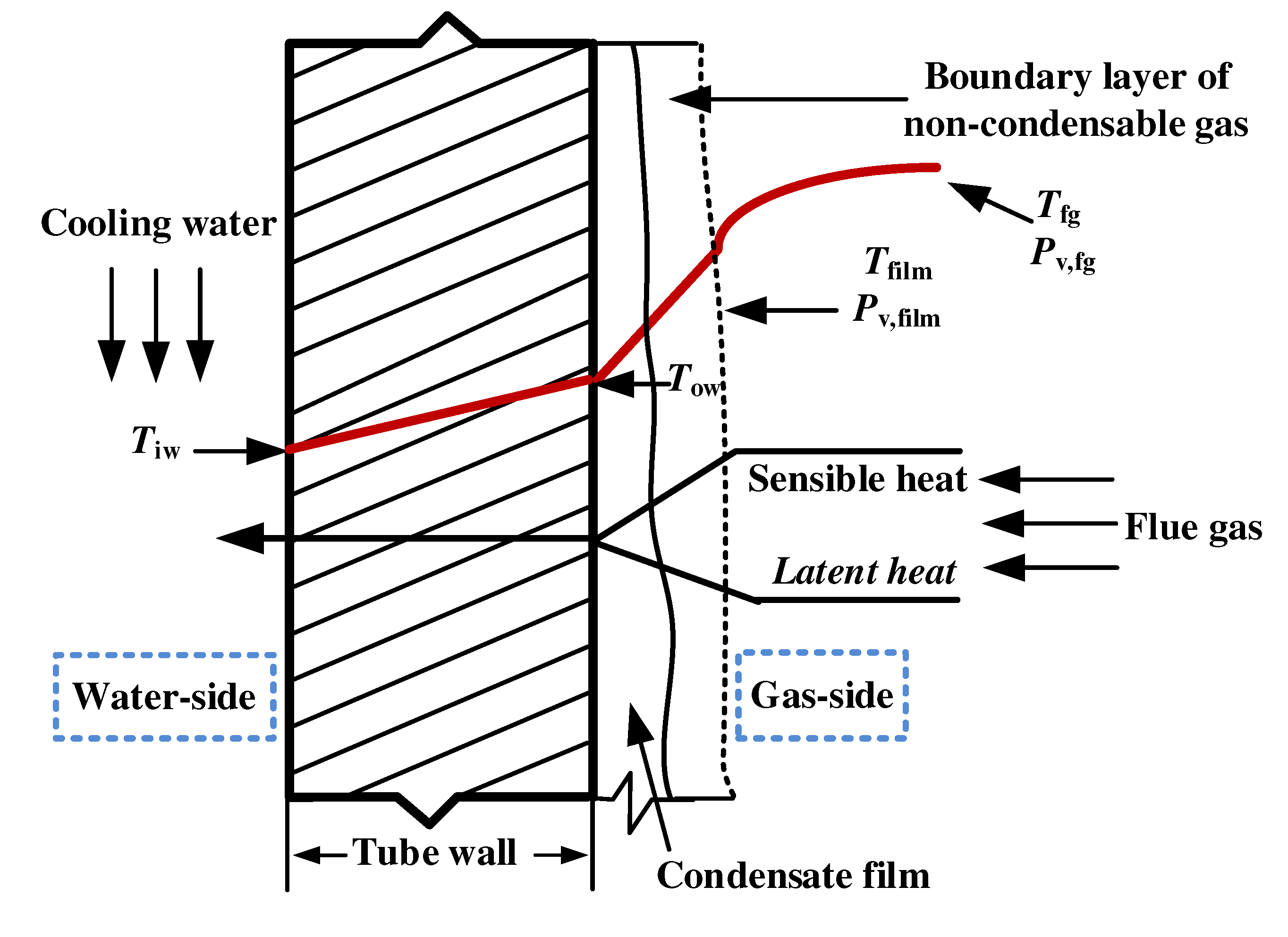
Figure 2.
Schematic of the condensing heat exchanger.
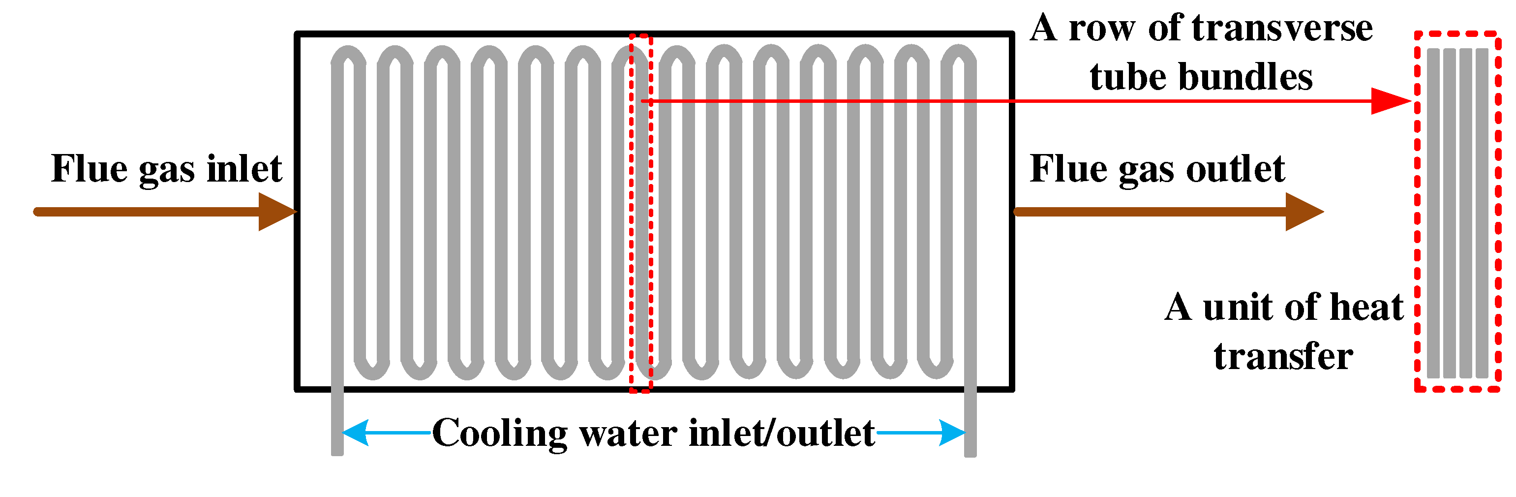
Figure 3.
Flow chart for the calibration calculation of the counter-flow heat exchange in a single heat transfer unit.
Figure 3.
Flow chart for the calibration calculation of the counter-flow heat exchange in a single heat transfer unit.
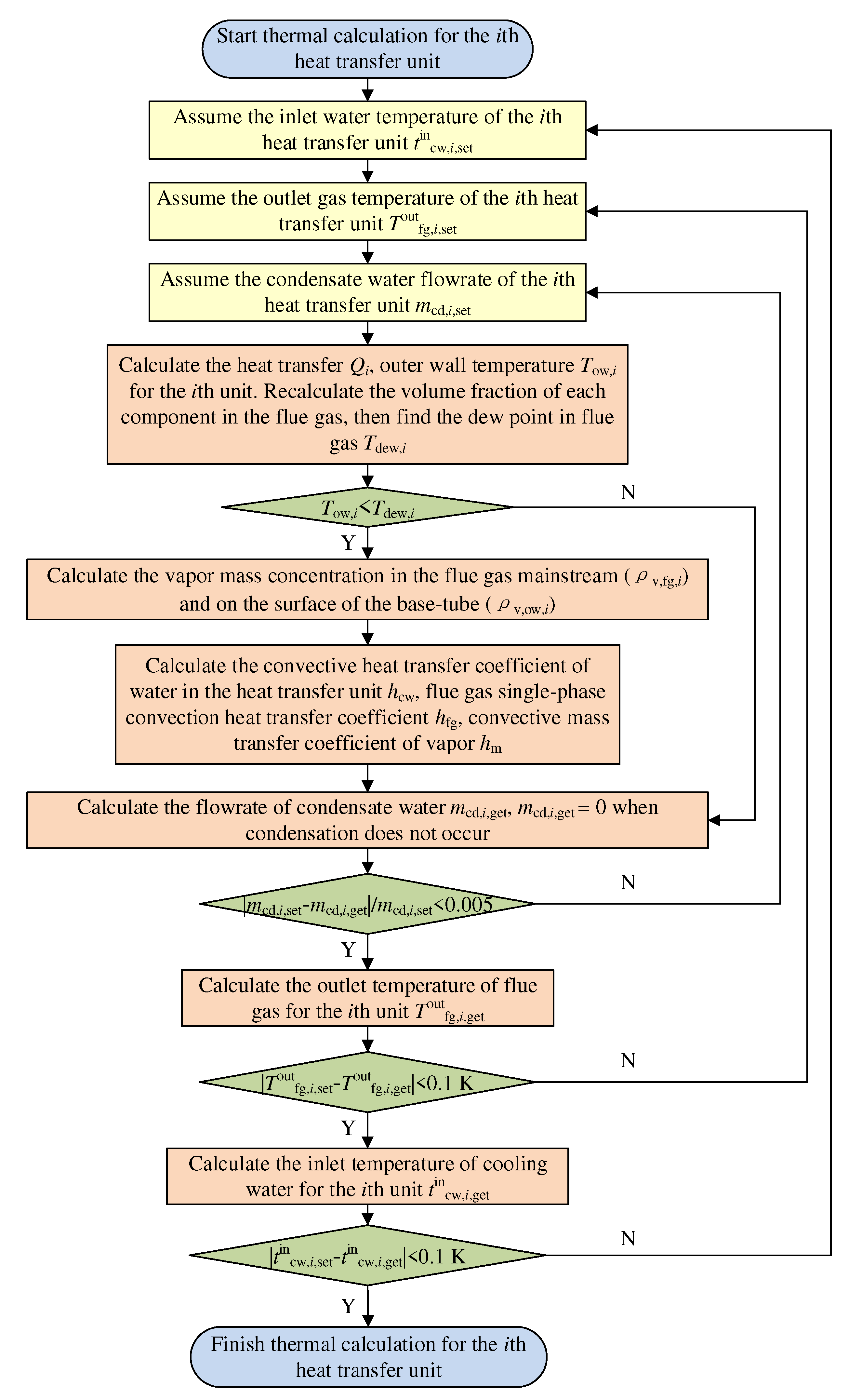
Figure 4.
Schematic diagram of the condensing heat exchanger.
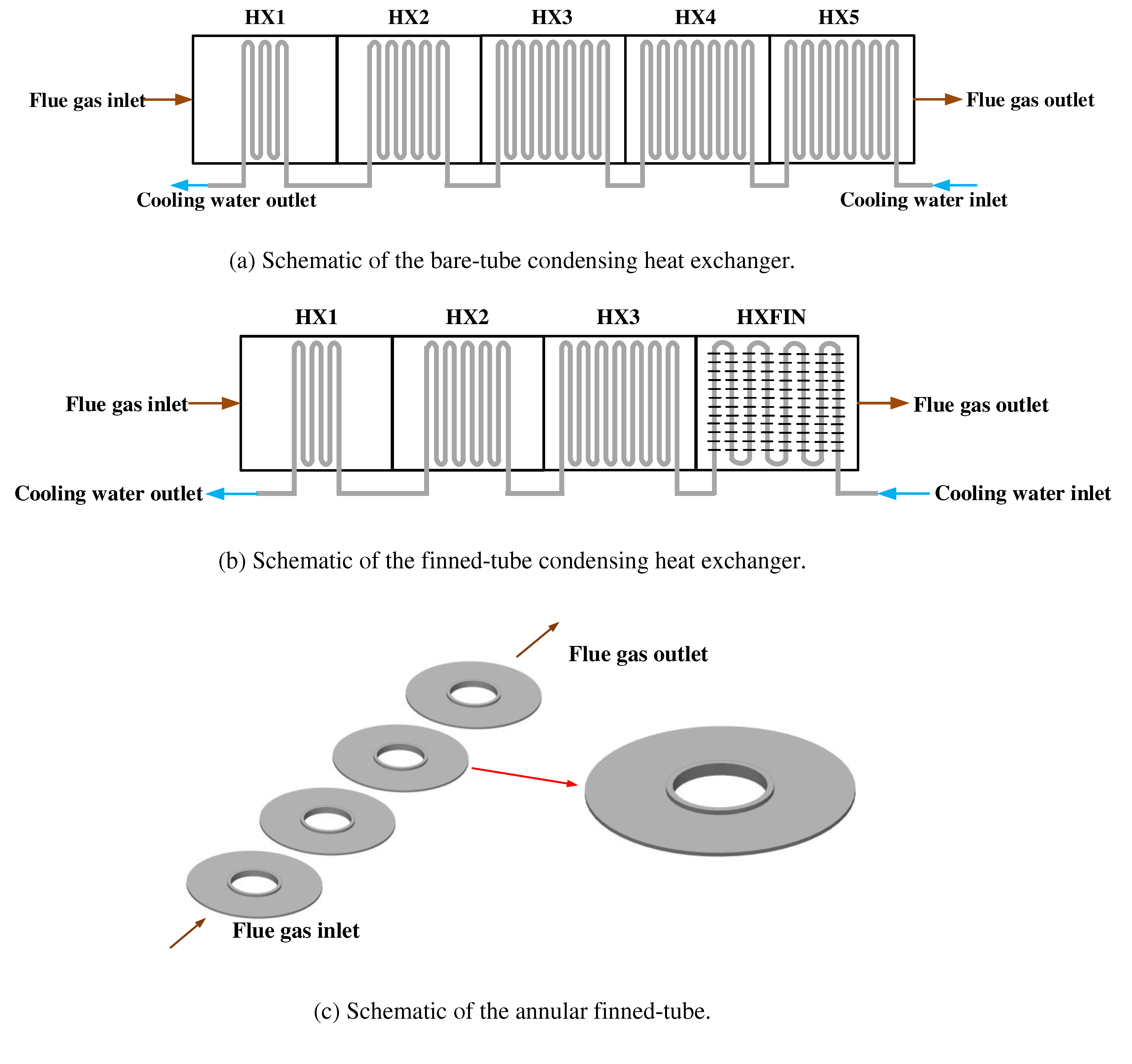
Figure 5.
Comparisons between the experimental and calculated results for 0108BL.
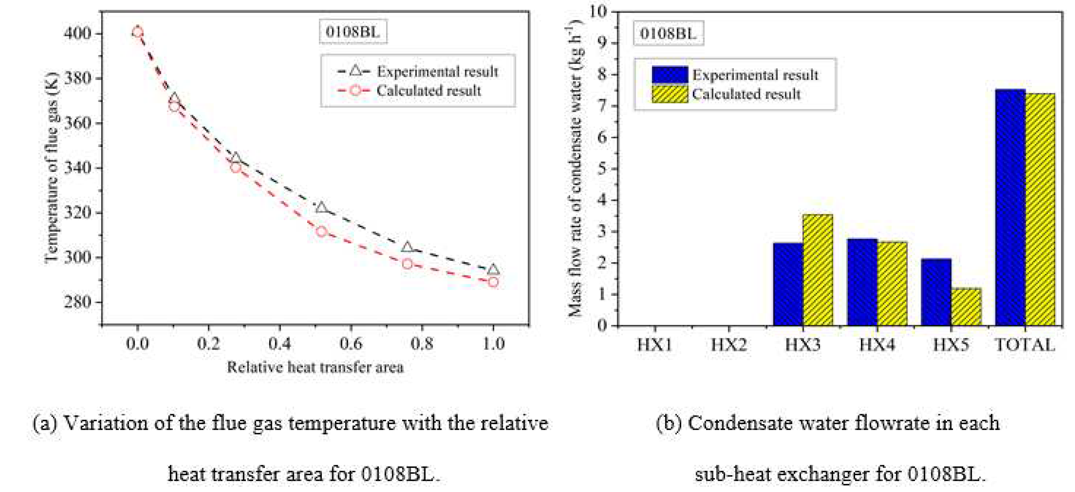
Figure 6.
Comparisons between the experimental and calculated results for 0731BLa.
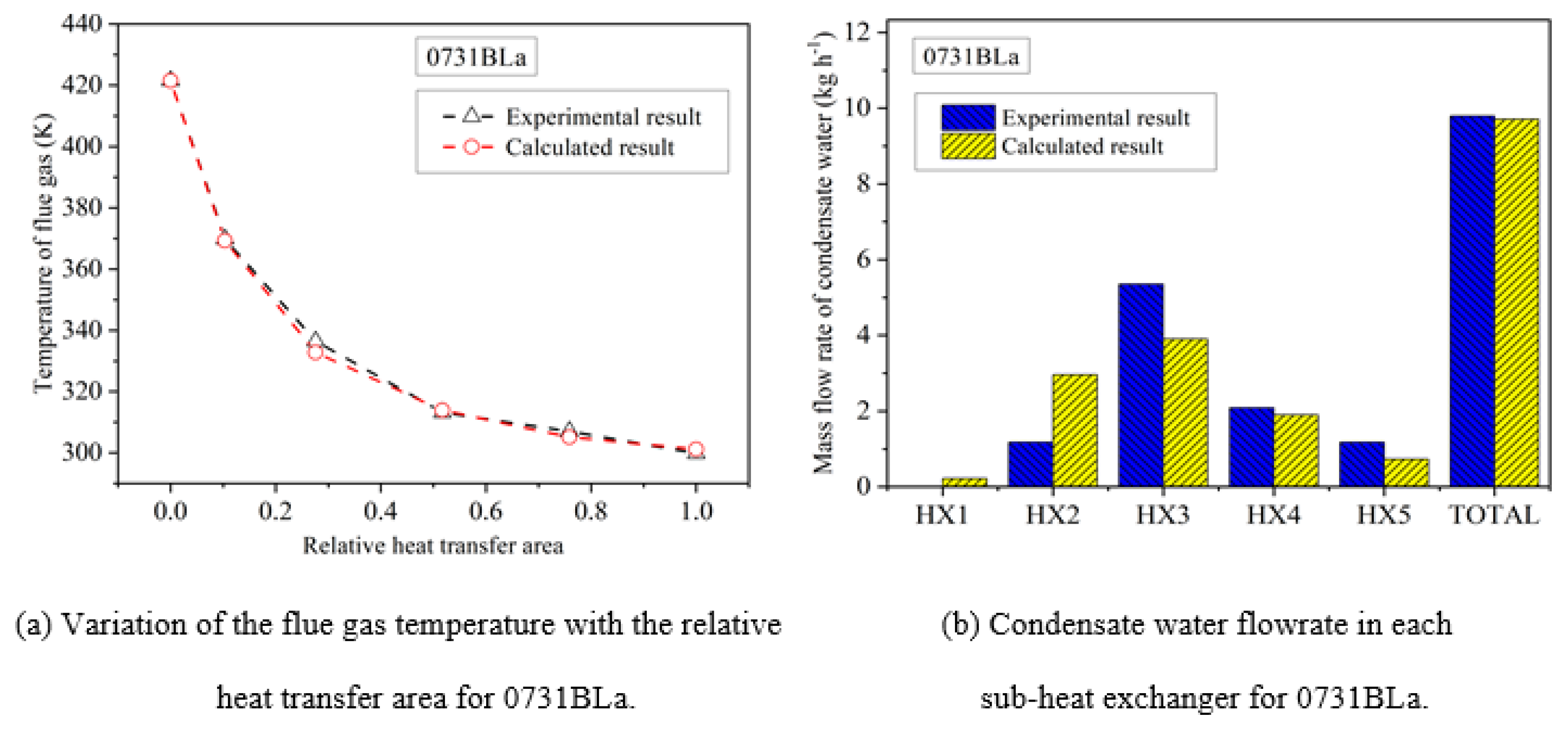
Figure 7.
Condensate water flowrate in each sub-heat exchanger.
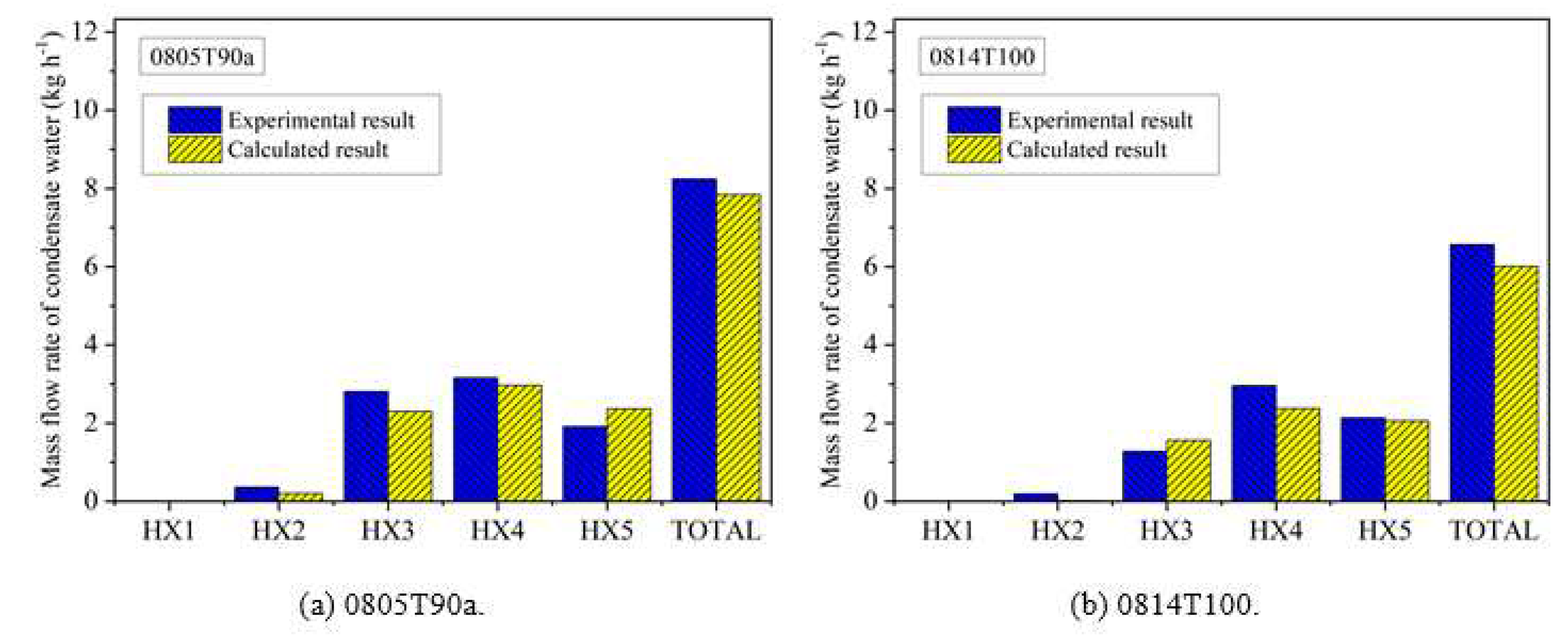
Figure 8.
Comparisons between the experimental and calculated results for 0718BL.
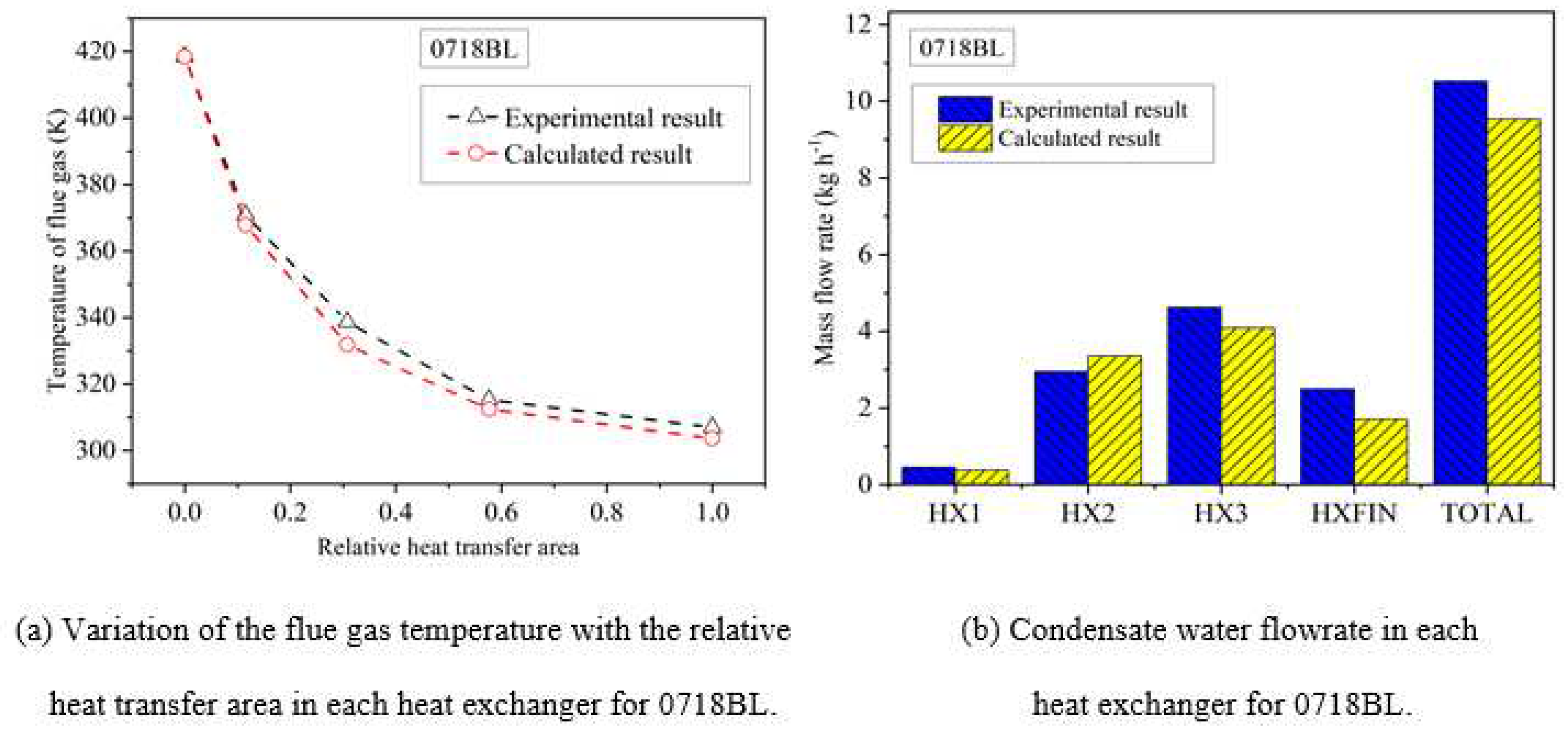

Table 1.
Cases setting for validation.
| Case No. | Flowrate of inlet flue gas (kg h-1) | Temperature of inlet flue gas (K) | Flowrate of inlet cooling water (kg h-1) | Temperature of inlet cooling water (K) | Inlet moisture fraction (%) |
|---|---|---|---|---|---|
| 0108BL | 199.5 | 400.9 | 332.0 | 282.8 | 7.7 |
| 0731BLa | 152.4 | 421.5 | 372.2 | 298.0 | 13.5 |
| 0718BL | 157.6 | 418.5 | 374.2 | 296.7 | 13.5 |
Table 2.
Parameters of each sub-heat exchanger.
| Parameters | HX1 | HX2 | HX3 | HX4 | HX5 | HXFIN |
|---|---|---|---|---|---|---|
| Cross-sectional width (mm) | 152.4 | 152.4 | 152.4 | 152.4 | 152.4 | 330.2 |
| Height of inlet cross-section (mm) | 355.6 | 355.6 | 355.6 | 355.6 | 355.6 | 136.53 |
| Height of outlet cross-section (mm) | 381 | 381 | 381 | 381 | 381 | 155.58 |
| Mean cross-section height (mm) | 368.3 | 368.3 | 368.3 | 368.3 | 368.3 | 146.05 |
| Tube’s outer diameter (mm) | 12.7 | 12.7 | 12.7 | 12.7 | 12.7 | 12.7 |
| Tube’s wall thickness (mm) | 0.889 | 0.889 | 0.889 | 0.889 | 0.889 | 1.24 |
| Transverse pitch (mm) | 18.34 | 18.34 | 18.34 | 18.34 | 18.34 | 26.99 |
| Longitudinal pitch (mm) | 50.80 | 50.80 | 50.80 | 50.80 | 50.80 | 101.6 |
| Number of transverse tube rows | 8 | 8 | 8 | 8 | 8 | 5 |
| Number of longitudinal tube rows | 6 | 10 | 14 | 14 | 14 | 8 |
| Type of tube bundle | Bare-tube | Bare-tube | Bare-tube | Bare-tube | Bare-tube | Finned-tube |
| Fin height | — | — | — | — | — | 6.35 |
| Fin thickness | — | — | — | — | — | 0.38 |
| Fin pitch | — | — | — | — | — | 4.55 |
| Layout of tube bundle | In-line | In-line | In-line | In-line | In-line | In-line |
Table 3.
Experimental and calculated results of the condensate water flowrate in the bare-tube heat exchanger.
Table 3.
Experimental and calculated results of the condensate water flowrate in the bare-tube heat exchanger.
| Case No. | Flowrate of inlet flue gas (kg h-1) | Temperature of inlet flue gas (K) | Flowrate of inlet cooling water (kg h-1) | Temperature of inlet cooling water (K) | Inlet moisture fraction (%) | Experimental measured condensate water flowrate (kg h-1) | Calculated condensate water flowrate (kg h-1) | Relative error (%) |
|---|---|---|---|---|---|---|---|---|
| 0110BL | 200 | 426.5 | 280 | 282.9 | 7.8 | 7.4 | 7.6 | -2.5 |
| 0112BL | 223 | 429.5 | 310 | 282.6 | 8.7 | 9.3 | 9.7 | -4.2 |
| 0116BL | 242 | 440.4 | 315 | 282.2 | 8.6 | 9.9 | 10.2 | -2.8 |
| 0118BL | 227 | 436.8 | 327 | 282.1 | 9.0 | 10.5 | 10.4 | 1.2 |
| 0119BL | 217 | 437.4 | 318 | 281.5 | 9.3 | 10.1 | 10.4 | -3.6 |
| 0302BL | 183 | 437.0 | 328 | 278.5 | 10.3 | 10.4 | 10.5 | -0.8 |
| 0323BL | 185 | 405.5 | 320 | 279.5 | 9.6 | 9.8 | 9.8 | 0.4 |
| 0302T55 | 179 | 415.1 | 571 | 286.5 | 11.4 | 11.0 | 11.0 | 0.0 |
| 0302T75 | 164 | 422.4 | 256 | 297.2 | 10.9 | 7.3 | 7.1 | 2.8 |
| 0302T90 | 162 | 424.0 | 185 | 305.5 | 10.5 | 4.1 | 3.4 | 17.4 |
| 0731BLb | 163 | 424.3 | 372 | 298.4 | 13.2 | 10.1 | 9.9 | 2.1 |
| 0731BLc | 158 | 421.4 | 371 | 298.4 | 13.2 | 9.8 | 9.6 | 2.2 |
| 0801T100 | 161 | 415.8 | 385 | 310.8 | 12.8 | 6.4 | 5.7 | 11.3 |
| 0805T90b | 185 | 410.2 | 662 | 304.4 | 12.3 | 9.3 | 8.9 | 3.4 |
| 0805T90c | 184 | 421.2 | 558 | 305.3 | 13.7 | 10.5 | 10.2 | 3.1 |
| 0805T90d | 183 | 425.9 | 519 | 305.9 | 14.5 | 10.8 | 10.8 | 0.7 |
| 0805T90e | 177 | 424.4 | 369 | 305.0 | 14.0 | 9.3 | 9.2 | 0.7 |
| 0806T90a | 181 | 419.5 | 653 | 304.4 | 13.1 | 10.0 | 9.7 | 3.0 |
| 0813BL | 186 | 423.7 | 363 | 298.5 | 13.0 | 10.8 | 10.5 | 2.9 |
| 0814BLa | 189 | 420.9 | 394 | 297.5 | 12.7 | 10.7 | 10.9 | -1.0 |
| 0814BLb | 192 | 421.0 | 393 | 297.7 | 11.9 | 9.9 | 10.0 | -0.5 |
| 0814BLc | 188 | 419.4 | 378 | 297.5 | 12.6 | 10.5 | 10.6 | -1.2 |
| 0815BL | 188 | 419.0 | 401 | 298.7 | 13.1 | 11.0 | 11.0 | 0.3 |
| 0815T100 | 182 | 415.2 | 404 | 311.1 | 13.2 | 7.3 | 6.5 | 10.6 |
| 0220BL | 253 | 439.3 | 345 | 278.1 | 12.3 | 16.0 | 17.2 | -7.6 |
| 0220T60 | 248 | 440.3 | 444 | 288.8 | 12.0 | 15.4 | 15.3 | 0.7 |
| 0220T70 | 240 | 440.0 | 290 | 294.8 | 10.9 | 10.7 | 9.3 | 13.4 |
| 0221BLa | 251 | 432.9 | 223 | 278.7 | 9.1 | 11.3 | 10.1 | 10.4 |
| 0221BLb | 263 | 440.2 | 440 | 278.0 | 11.2 | 16.3 | 16.7 | -2.8 |
| 0221BLc | 267 | 439.9 | 542 | 277.9 | 12.8 | 20.2 | 20.0 | 1.3 |
Table 4.
Experimental and calculated results of the condensate water flowrate in the finned-tube heat exchanger.
Table 4.
Experimental and calculated results of the condensate water flowrate in the finned-tube heat exchanger.
| Case No. | Flowrate of inlet flue gas (kg h-1) | Temperature of inlet flue gas (K) | Flowrate of inlet cooling water (kg h-1) | Temperature of inlet cooling water (K) | Inlet moisture fraction (%) | Experimental measured condensate water flowrate (kg h-1) | Calculated condensate water flowrate (kg h-1) | Relative error (%) |
|---|---|---|---|---|---|---|---|---|
| 0518BL | 181 | 388.5 | 283 | 283.1 | 8.3 | 7.0 | 7.2 | -2.7 |
| 0518T50 | 173 | 386.7 | 197 | 284.1 | 8.4 | 6.8 | 6.3 | 7.7 |
| 0518T70 | 176 | 386.3 | 393 | 294.6 | 9.5 | 7.6 | 7.0 | 7.9 |
| 0523BLa | 179 | 386.8 | 295 | 283.3 | 7.7 | 6.0 | 6.5 | -8.4 |
| 0523BLb | 178 | 387.0 | 301 | 283.4 | 8.1 | 6.3 | 6.9 | -9.1 |
| 0523BLc | 173 | 386.1 | 298 | 283.5 | 7.9 | 6.0 | 6.6 | -8.9 |
| 0523T65 | 159 | 383.0 | 555 | 291.5 | 11.0 | 8.8 | 8.6 | 2.5 |
| 0523T80 | 157 | 383.2 | 317 | 300.1 | 7.8 | 3.9 | 3.5 | 10.8 |
| 0523T100 | 155 | 382.7 | 223 | 310.3 | 8.8 | 1.4 | 1.4 | 2.6 |
| 0606BL | 173 | 396.5 | 273 | 284.4 | 9.7 | 8.2 | 8.3 | -1.8 |
| 0606T55 | 167 | 388.7 | 294 | 285.8 | 12.2 | 10.6 | 10.7 | -0.4 |
| 0606T70 | 169 | 389.7 | 447 | 294.4 | 11.9 | 10.0 | 9.7 | 2.9 |
| 0608BL | 157 | 387.3 | 274 | 285.4 | 11.9 | 9.4 | 9.8 | -4.1 |
| 0608T55 | 130 | 385.0 | 275 | 286.2 | 14.7 | 10.4 | 10.7 | -2.9 |
| 0608T80 | 137 | 385.0 | 272 | 301.0 | 12.7 | 7.0 | 6.8 | 2.4 |
| 0627BL456 | 118 | 378.8 | 271 | 287.0 | 15.0 | 9.8 | 9.9 | -1.6 |
| 0628BL456 | 150 | 381.9 | 263 | 286.5 | 12.4 | 10.0 | 9.7 | 2.6 |
| 0629BL45 | 151 | 383.6 | 287 | 287.0 | 9.5 | 5.9 | 6.8 | -16.0 |
| 069BL456 | 148 | 382.8 | 274 | 287.0 | 10.6 | 7.9 | 7.9 | -0.6 |
| 0717BLa | 177 | 407.5 | 352 | 296.2 | 12.0 | 10.1 | 9.0 | 10.8 |
| 0717BLb | 158 | 411.0 | 354 | 296.0 | 12.1 | 9.1 | 8.5 | 7.3 |
| 0717BLc | 135 | 413.0 | 364 | 296.5 | 13.6 | 9.2 | 8.7 | 5.0 |
| 0717BLd | 135 | 414.3 | 373 | 296.0 | 13.8 | 9.4 | 9.0 | 4.0 |
| 0717BLe | 140 | 418.6 | 373 | 296.0 | 11.8 | 7.9 | 7.5 | 5.5 |
| 0717BLf | 148 | 418.9 | 373 | 297.0 | 11.8 | 8.3 | 7.8 | 5.1 |
| 0718T100c | 155 | 416.5 | 369 | 311.0 | 13.6 | 7.1 | 5.7 | 19.4 |
| 0719BL | 154 | 417.4 | 373 | 296.5 | 13.3 | 10.2 | 9.4 | 7.3 |
| 0719T90a | 155 | 420.4 | 604 | 305.3 | 14.2 | 9.6 | 9.0 | 6.2 |
| 0719T90b | 156 | 410.3 | 597 | 305.2 | 13.8 | 9.3 | 8.6 | 7.4 |
| 0719T90c | 138 | 407.3 | 583 | 305.0 | 14.2 | 8.5 | 8.1 | 5.3 |
Disclaimer/Publisher’s Note: The statements, opinions and data contained in all publications are solely those of the individual author(s) and contributor(s) and not of MDPI and/or the editor(s). MDPI and/or the editor(s) disclaim responsibility for any injury to people or property resulting from any ideas, methods, instructions or products referred to in the content. |
© 2023 by the authors. Licensee MDPI, Basel, Switzerland. This article is an open access article distributed under the terms and conditions of the Creative Commons Attribution (CC BY) license (http://creativecommons.org/licenses/by/4.0/).
Copyright: This open access article is published under a Creative Commons CC BY 4.0 license, which permit the free download, distribution, and reuse, provided that the author and preprint are cited in any reuse.


