
Submitted:
06 September 2023
Posted:
11 September 2023
You are already at the latest version
Abstract
This paper presents a comprehensive evaluation of metal foam employment within polymer electrolyte fuel cells (PEFCs) and compares it with conventional serpentine channels from both experiment viewpoints and computational fluid dynamics simulation. The experiments are designed to study the effects of material, area density, compression ratio, and final thickness of metal foam. Additionally, the influence of housing plate material and relative humidity (RH) is also tested for the first time. The results reveal that at RH=75-100%, the best distributor design is nickel foam with a compression ratio of 70%, a final thickness of 0.5mm, and SS-304 housing plate, which delivers 3110 mA cm-2 as limiting current density that is scarce in the literature. The PEFC with this foam distributor shows a 10% improvement in maximum power density and 45% in limiting current density compared to the serpentine channel case. While at RH=30%, the same foam flow field with a final thickness of 1mm is a superior option. The experiments also indicate that maximum power density increases by 23% as the compression ratio rises from 0 to 70%, while reducing final thickness from 1 to 0.5 mm causes a 19% enhancement in cell performance. Simulation results reveal that metal foam is more successful in evenly reactant distribution so that the average oxygen mass fraction at the cathode catalyst layer is increased by 38% in the metal foam case compared to the serpentine channel.
Keywords:
Metal foam distributor
; Compression ratio
; Limiting current density
; Maximum power density
; Serpentine channel
; Uniform distribution
1. Introduction
Fuel cells have emerged as a promising and environmentally friendly energy conversion technology, offering the efficient conversion of chemical energy into electrical energy with minimal indirect greenhouse gas emissions. Among the various fuel cell types, polymer electrolyte fuel cells (PEFCs) have garnered significant attention for their potential application in diverse fields, such as transportation, stationary power generation, and portable electronic devices. To harness the full potential of PEFCs and address the challenges of mass transport and reactant distribution, effective flow field design is essential.
Traditional flow field designs in PEFCs, such as serpentine and parallel channels, have been widely adopted due to their simplicity and manufacturability [1]. However, these conventional flow field configurations often suffer from issues such as pressure drop [2], flow maldistribution [3], and limitations in water management [4], which can hamper the overall performance and durability of the fuel cell.
In recent years, extensive research has been conducted to explore novel flow field configurations that can address these challenges and improve the performance of PEFCs. Among these advancements, the application of metal foam as a flow field in fuel cells has shown promising potential [5,6]. Metal foams, characterized by their high surface area, interconnected porosity, and excellent thermal conductivity, present unique opportunities for enhancing mass transport [7], improving reactant distribution [8], and water management capability [9] within PEFCs. The incorporation of metal foam as a flow field introduces several advantages over conventional flow field designs. The high porosity and interconnected pores of metal foam promote efficient reactant distribution, reducing reactant depletion, uniform temperature and pressure distribution, weight reduction [10] and enhancing cell performance [11]. Additionally, the three-dimensional structure of metal foam enhances the removal of reaction by-products, leading to reduced concentration gradients and minimized performance degradation [12].
Recent studies have explored various aspects of metal foam flow fields, ranging from design, optimization, and manufacturing techniques to electrochemical performance evaluation. For instance, Park et al. conducted a series of research about graphene foam flow field superiority compared to the conventional serpentine type [7,13]. They suggested to use graphene foam with in-plane and through-plane pores to play the roles of both channel-rib and gas diffusion layer (GDL) [13]. Their experiments showed that the graphene foam could mitigate the mass transport resistance by applying more uniform reactant distribution and enhancing water droplets removal [7]. In an analytical model, Jo and Ju investigated the effect of using metal foam instead of a parallel serpentine flow field [14]. They reported that although using metal foam-based flow fields leads to less severe oxygen depletion and more uniform current density profiles owing to the absence of channels and ribs, however, it also experiences weaker convective flow, while the parallel serpentine flow field has stronger convective over-rib flow due to the pressure gradient between two neighboring channels. So, metal foam flow fields are susceptible to water accumulation especially for high relative humidities. Although this condition is suitable for membrane hydration, it is unfavorable water removal and flooding suppression [14]. This topic has been studied in another experimental research by Wu et al. [15] who compared the formation, accumulation and removal of water between metal foam and conventional serpentine flow-fields using in-operando neutron radiography in their experiments. They revealed that metal foam PEFCs are resistant to dehydration so that they may be susceptible for water accumulation especially at low current density.
Based on the literature, using a metal foam flow field as an alternative to the conventional serpentine channels has advantages, including fluid flow uniformity and monotonic distribution of current density [16] and temperature [17], which enhance the fuel cell performance and avoid occurring local hotspots within the MEA consequently increase the lifetime. Pressure drop and parasitic pumping power are considerably lower in metal foam flow fields than in serpentine type [15], which helps to achieve higher levels of net power. However, based on Ref. [18], there is also a lower limit for pressure gradient from the inlet to the outlet, which causes drag of the produced liquid water droplets in the cathode electrode and removes them to the outside of the cell to prevent flooding. This low-pressure condition is one of the metal foam flow-field weak points which leads to more liquid water accumulation and flooding [15]. The other metal foam disadvantage is high electrical contact resistance caused due to low contact area between the solid parts of foam and MEA and current collector [19]. This problem could be mitigated by compressing the metal foam between the MEA and the current collector [20]. The in-plane pores are shrunk in compressed metal foam [7] leads to shorten the electron transfer path and increases the contact area between the sandwiched metal foam and the MEA and current collector. Meanwhile, the through-plane pores remain large enough to conduct the reactant flow to the MEA [7]. It is worth noting that placing a porous layer with a pore-scale size larger than the catalyst layer and smaller than foam (such as GDL or micro-porous layer, MPL) leads to reducing the contact resistance between foam and MEA [21]. Maybe as the last demerit, metal foams suffer from low resistance against corrosion [22], which also happens in metallic bipolar plates (BPP) [23] and graphite and graphene foams [13,15]. To solve this problem, different kinds of anti-corrosion and hydrophobic surface coating, including Teflon (PTFE) [6], Ni/Sn electrodeposition [24], and reduced graphene oxide (rGO) [25], are suggested.
The research papers in the literature reveal that morphology (pore density, porosity, area density (mass per unit area), permeability, tortuosity, pores interconnections), structure (thickness, compression ratio), and material of the foam used as flow-field in PEFCs have essential roles to overcome metal foams’ drawbacks and improve fuel cell performance [26,27,28]. Zhang et al. presented a 3D computational fluid dynamics (CFD) model of the complete morphology of metal foam [26]. Their results showed that local velocities varied greatly, and the reactant gas could be transferred into the catalyst layer more uniformly and easily due to the metal foam structure. In an experimental study, Chen et al. studied the influence of PPI, compression ratio, and thickness of the metal foam [9] on fuel cell performance. They showed that there is an optimal PPI for cathode foam due to the trade-off between gas flow uniformity and liquid water removal, while for the anode foam, the higher the PPI, the more the hydrogen uniformity and the higher the cell performance. Chen et al. also indicated that the flooding issue will be addressed by increasing the cathode foam compression ratio, while there is an optimum value for compression ratio of the anode foam [9].
In light of the recent research and the increasing interest in metal foam as a flow field in fuel cells, this paper aims to present a comprehensive and exact evaluation of metal foam flow field application within PEFCs from both simulation and experiment viewpoints. It is tried to design a metal foam flow field to mitigate the concentration loss that occurs at high current densities and increases the limiting current density to values that have not been reported in the literature yet. In this regard, the influence of foam material and current collector (housing plate) material has been investigated on the fuel cell performance experimentally for the first time. Also, the fuel cell performance is evaluated through experiments at different operating relative humidity conditions for both foam-based and serpentine flow fields as novel research. In the following, the effect of some other determinative parameters, such as compression ratio (CR) and final thickness of the metal foam, is also investigated on fuel cell performance. In addition, to complete the evaluation, the performance of fuel cell with the best case of the metal foam flow field is compared with that of the conventional single serpentine channel. Finally, to have a comprehensive, thorough, and insightful analysis of the current events, complete 3D and two-phase CFD models have been developed for both PEFCs with metal foam and serpentine channel flow fields. The results of the simulation are used to perform a careful examination of the transport phenomena inside the proposed metal foam flow field and compare it with the serpentine type. As far as we know, experimental research about the metal foam flow field behavior that is enriched and analyzed by a complete CFD model is scarce in the literature. Thus, the current paper plays a crucial role in introducing transport phenomena inside these flow fields and the distinction and superiority of metal foams over conventional serpentine flow fields.
2. Experiments
In this study, the performance of designed PEFCs equipped with a metal foam flow field for the cathode side has been tested and compared with the conventional serpentine flow field type. In this regard, a single-channel serpentine flow field is designed for the anode bipolar plate in all cases of the test. Meanwhile, for the control sample, the same bipolar plate is also considered for the cathode side and is compared with the PEFC with the metal foam-based flow field as the intervention groups. Details have been explained in the following sections.
2.1. Flow fields
Two kinds of flow fields, including metal foam and single serpentine channel, have been designed for the current study, which will be explained in the following:
2.1.1. Metal foam
The characteristics of metal foams used in this study are described in detail in this section. Both copper and nickel foam materials with an initial thickness of 1 mm were used as cathode flow fields. These foams are named Foam I-Cu and Foam I-Ni, respectively, and have been scanned by scanning electron microscope (SEM). The results of SEM images in Figure 1a,b reveal a mean pore size of 450 μm and 250 μm for Foam I-Cu and Foam I-Ni, respectively. These pore sizes correspondingly reflect a pore density of 56 and 101 PPI. According to the top and side view SEM images of Foam I-Cu and Foam I-Ni in Figure 1a,b, the copper foam has a higher area density than the nickel one, it is 1000 g cm-2 for Foam I-Cu and 750 g cm-2, for Foam I-Ni, respectively.
It is worthwhile to mention that nickel foam with different initial and final thicknesses has also been used to investigate the effect of both the compression ratio (CR=(tini-tfin)/tini, where tini and tfin are initial and final thicknesses, respectively) and the final thickness. Nickel foam, named Foam I-Ni, has a 1 mm initial thickness which is the same as housing depth; thus, CR is zero in this case. While nickel foam, named Foam II-Ni, has a 1.7 mm initial thickness and is compressed to 1 mm (housing depth), in which CR is about 40%. Nickel Foams III-Ni and IV-Ni consist of two foams of 1.7 mm initial thickness, which are compressed to 1 mm so that CR is about 70%. Finally, nickel Foam V-Ni is a foam with a 1.7 mm initial thickness which is compressed to 0.5 mm; therefore, CR is about 70%. A summary of all used metal foam cases is reported in Table 1. To study the effect of housing plate material, graphite housing plate is used for Foams I, II, and III, while SS-304 housing plate is used for Foams IV and V. It is significant to note that in order to protect the MEA and prevent any damage, the compression process was performed using a Teflon gasket mold with the thickness of the same as the required final thickness. The pristine metal foam was placed in the Teflon gasket mold and compacted by cold press.
The SEM images of all aforementioned nickel foams, which were prepared after compression, are illustrated in Figure 1. Comparing the SEM image, the pristine nickel foam without compression (Foam I-Ni) in Figure 1b to those of compressed nickel foams (Foams II-Ni, III-Ni, IV-Ni, and V-Ni) in Figure 1c–e, one can say the mean size of through-plane pores (top view images) remains the same due to the vertical pressing process, while the mean size of in-plane pores (side view images) is decreased from the pristine Foams I-Ni with CR = 0 to compressed Foams V-Ni with CR ≈ 70% which leads to reduce the in-plane permeability. This issue provides a more uniform flow distribution over the catalyst layer surface via through-plane pathways and a higher contact area due to the compressed in-plane pores.
2.1.2. Serpentine channel and housing plate
A single-channel serpentine flow field has been designed from a graphite housing plate for an active surface of 21.6⤫21.7 mm2 as both the anode and the cathode bipolar plates in all test runs as the control sample. A single channel pattern with a width of 0.8 mm, height of 1 mm, and rib width of 0.8 mm is CNC machined on a graphite housing plate. It will be shown in Figure 2c.
It should be noted that two types of housing plates are also designed for the metal foam flow fields; the first one is made from graphite with a depth of 1 mm, which is shown in Figure 2b, and the second one is made from SS304 with the depth of both 1 and 0.5 mm.
2.2. PEFC experiment
To have a complete sight of the PEFC sample, an exploded view of the single-cell PEFC with metal foam distributor on the cathode side and serpentine flow field on the anode side, which is used in current research, is shown in Figure 2a. The end plates, current collectors, bipolar plates (serpentine channel/metal foam for cathode and serpentine channel for anode), and the MEA, which is sealed by a gasket, are shown in this figure. The graphite housing plate, which metal foam is placed inside, is shown in Figure 2b; also, the serpentine flow field is illustrated in Figure 2c. Also, a view of the copper and nickel foam used is shown in Figure 2d.
A 21.6⤫21.7 mm2 gas diffusion electrode (GDE) (Johnson Matthey, with 0.6 mg cm−2 Pt loading) was used for the anode and the cathode sides. The anode GDE, the cathode GDE, and the membrane (Nafion 211, Chemours, Wilmington, DE, USA) were assembled by hot pressing at 135oC for 4 min, with 2 of those minutes being under compression weight of 0.125 tones. The MEA was then assembled into a single cell and tested using a fuel cell test station (850e, Scribner Associates, Southern Pines, NC, USA). Hydrogen and air with a controlled temperature of 80oC and the desired relative humidities of 100%, 75%, and 30% were applied to the anode and cathode sides.
3. CFD-Model descriptions
A 3D computational fluid dynamics model has been implemented to simulate all the transport phenomena within the PEFC. In this regard, to cover all tested cases, two solution domains have been considered here. The first one is used to model the serpentine flow field as the control sample, which contains current collectors (CCs), single channel serpentine flow fields for both anode and cathode sides, gas diffusion layers (GDLs), anode and cathode catalyst layers (ACL and CCL), and the polymer electrolyte membrane (Mem). Also, a structural full hexahedral mesh grid has been established for this solution domain. It is tried to decrease the mesh grid size near the catalyst layers where there are high gradients of different parameters due to consumption/production to capture the variations. This solution domain and its mesh grid are shown in Figure 3.
The second solution domain is considered to model the PEFC with a foam-based flow field. In this model, the cathode serpentine channel with its current collector is substituted by a metal foam flow distributor with its housing current collector plate, as shown in Figure 3. Exactly like before, and a structural full hexahedral mesh grid is also developed in this case which is shown in Figure 3.
The main assumptions are also listed as follows:
- (i)
- The PEFC operates under steady-state conditions.
- (ii)
- The gas reactants are considered to be as ideal gas.
- (iii)
- The gravity effect is negligible.
- (iv)
- The GDLs are isotropic porous media from carbon fiber, and the pressure drop is modeled by a linear relation with fluid velocity, Darcy law.
- (v)
- The foams are isotropic porous media from Cu/Ni, and the pressure drop is modeled by quadratic relation with fluid velocity, Forchheimer law.
- (vi)
- Mist flow is considered for the serpentine channel, which means that the velocity of the liquid droplets is equivalent to the gas, and they are carried by high gas speed and disappear as entering into the channels.
- (vii)
- The membrane is impermeable to gases and transfers the protons and dissolved water.
- (viii)
- ACL and CCL are porous media that have triple phase zones (TPZ), including Pt/C particles for electron transferring, ionomer for proton transferring, and void pores for reactant gases transferring.
3.1. Governing equations
The governing equations form a system of eight main equations, including conservations of (a) mass, (b) momentum, (c) species, (d) energy plus four scalar equations for conservations of (e) electric charges, (f) protonic charges, (g) liquid water saturation, and (h) dissolved-water. These equations are reported in Table 2 [29,30].
where the parameters are introduced as follows: , , , and are the density, velocity vector, viscosity, and heat capacity of the reactant gas flow, respectively, , , , , and are the effective porosity, the effective diffusion coefficient of species k in the mixture, effective thermal conductivity, electrical conductivity, and protonic conductivity within porous media, respectively, is the mass fraction of component k, P and T are the pressure and temperature of the flow, respectively, and are electric and protonic potential, respectively, and are the volumetric reaction rates of oxygen reduction reaction within CCL and hydrogen oxidation reaction within ACL, respectively, s is liquid water saturation level, is the interfacial drag coefficient, is liquid water density, is the capillary diffusion coefficient, is water content within the ionomer phase, is the electro-osmotic drag coefficient, F is Faraday constant, and EW are the density and molecular weight of dry membrane, respectively, is the diffusion coefficient of dissolved water. Finally, , , , , , and represent the source terms of mass, momentum, species, energy, liquid water, and dissolved water due to the consumption/production and phase changing, respectively. All these source terms and the algebraic relations of the required parameters have been adjusted according to the details which have been described in Ref. [29,30], so to cut a long story short, it is avoided to give details again here. The remaining input parameters used in this model are reported in Table 3.
3.2. Model input parameters
Here, it was tried to set correct and exact data for all the input parameters, which have a vital role in outputs and results. Therefore, the value of all geometrical, electrochemical, material/structural, transport properties, and operating conditions are determined in Table 3 with special delicacy and sensitivity according to our experiments and also literature data.
3.3. Solution procedures
Eight governing equations mentioned in Table 2 are solved in the commercial software of Ansys-Fluent® 2022. First of all, a high quality, structural, full hexahedral mesh grid with small resolution around the MEA is developed to discretize the governing equations (see again Figure 2). Then, in case of spatial discretization, the least squares cell-based method is used for the gradient terms, while the standard method is used for pressure and first-order upwind for density, momentum, H2 mass fraction, O2 mass fraction, vapor mass fraction, energy, electric potential, protonic potential, water saturation level, and dissolved water. To handle the pressure-velocity coupling, SIMPLE algorithm is used. A set of trial-error has been performed to set the best values for under-relaxation factors to improve the convergence rate. The F-cycle method is used as a multigrid algorithm with a modified termination factor and bi-conjugate gradient stabilized method (BCGSTAB) for the species and scalars equations. Two sets of criteria are adjusted for iterative convergence; the first one is a residual target value of for the continuity, momentum, and species equations, and the second one is less than relative variation in average current density at a specified condition.
4. Results and discussions
The results and findings of current research have been described in this section. Firstly, the experimental results have been explained; secondly, the numerical simulation is validated against the experiments, and it is tried to examine the experimental observations and events inside the fuel cell carefully using the simulation.
4.1. Comparing Foam I-Cu and Foam I-Ni
From the experiment, the performance of PEFCs with Foam I-Cu and Foam I-Ni flow fields have been compared in Figure 4. The results indicate that the foam material and its area density have a significant impact on fuel cell performance so that the PEFC with copper foam (Foam I-Cu) and area density of 1000 g cm-2 delivers more current and power densities at high voltage range from OCV to 0.5 V compared to the PEFC with nickel foam (Foam I-Ni) with area density of 750 g cm-2, e.g., at V=0.7 V the PEFC with Foam I-Ni generates about 500 mA cm-2 current density while for Foam I-Cu case it is 714 mA cm-2 (43% higher). It is due to the higher area density of Foam I-Cu, compared to Foam I-Ni, which is shown before in Figure 1, on the one hand, and the greater electrical conductivity of Foam I-Cu compared to Foam I-Ni, see Table 3, on the other hand. The higher foam area density leads to an increase in the contact surface between the foam and the GDL and current collector [28], which yields a reduction in the ohmic resistance. Also, as a matter of fact, the higher the electrical conductivity, the lower the ohmic resistance at a high voltage range. Contrary to the high voltage range, the PEFC with Foam I-Ni experiences higher current and power densities at a low voltage range beneath 0.5 V compared to the Foam I-Cu case. The reason is that the higher foam area density in Foam I-Cu limits the access routes for the reactant gas flow and increases the mass transport resistance, especially at high current densities where the liquid water production is more significant. As a result, all of these events show their effects in restricting the limiting current density of the PEFC with Foam I-Cu in about 1820 mA cm-2 compared to that of the PEFC with Foam I-Ni which is 2580 mA cm-2 (42% higher). However, the maximum power density in both cases is almost the same and equal to about 684-701 mW cm-2, which occurs at 1270 and 1560 mA cm-2 for the PEFC with Foam I-Cu and Foam I-Ni, respectively.
4.2. Effect of compression ratio in Foams I-Ni, II-Ni, and III-Ni
To address the problem of high ohmic resistance and also increasing the low contact area, especially for PEFC with Foam I-Ni, the effect of metal foam compressing is also evaluated here. The performance of PEFC with Foam II-Ni with a compression ratio of 40% (from initial thickness 1.7 mm to final thickness 1 mm) and PEFC with Foam III-Ni with a compression ratio of 70% (from initial thickness 3.4 mm to final thickness 1 mm) are tested and compared with that of Foam I-Ni with no compression in Figure 4. As expected, reducing the thickness by compressing leads to increase the contact area of the nickel foam which sandwiched between the current collector and the GDL, as shown before in SEM images of Figure 1. Therefore, the electron transferring is facilitated, and the ohmic loss decreases at a high voltage range. Hence, the performance (current and power densities) of PEFCs with Foam II-Ni and Foam III-Ni shows improvement compared to PEFC with Foam I-Ni so that they reach PEFC performance with Foam I-Cu for voltage range OCV-0.6 V. For voltage lower than 0.6 V, the performance of PEFC with Foam III-Ni with CR=70% is highest and followed by PEFCs Foam II-Ni with CR=40% and Foam I-Ni with CR=0. So, the maximum power density improves from 684 mW cm-2 for PEFC with Foam I-Ni to 774 and 841 mW cm-2 for PEFCs with Foam II-Ni and Foam III-Ni, respectively. It is worthwhile to note that despite reducing the nickel foam thickness through compressing, the mass transfer resistance does not decrease, so all PEFCs with Foam I-Ni, Foam II-Ni, and Foam III-Ni have almost the same limiting current density as high as 2580-2710 mA cm-2. Because just the in-plane pores have been shrunk to increase the contact area while the through-plane pores remain almost intact and provide the required pathways for reactant supply at high current densities (see again Figure 1). As a result, increasing the compression ratio (CR) from 0 to 70% could cause a 23% enhancement in maximum power density.
4.3. Effect of housing material for Foams III-Ni and IV-Ni
Graphite and SS-304 were considered for testing the influence of housing plate material (current collector) for Foams III-Ni and IV-Ni with the same characteristics. According to performance results in Figure 4, the PEFC with SS-304 housing plate has higher performance compared to that of graphite housing at a high voltage range, from OCV to 0.4 V. While it is completely reversed in voltages less than 0.4 V. SS-304 has higher electron conductivity compared to the graphite one ( S m-1 against S m-1) [31,32], which mitigates the ohmic resistance at high voltage and improves the maximum power density to 935 mW cm-2. In comparison, it is 841 mW cm-2 for the PEFC with graphite housing plate. On the other hand, the SS-304 housing plate has a hydrophilic surface with a lower contact angle for liquid water droplets compared to the graphite, which has a hydrophobic surface [33,34,35]; this issue has a negative effect on the fuel cell performance especially at high current densities due to the liquid water accumulation (flow field flooding). Thus, the limiting current density in PEFC with SS-304 housing plate (Foam IV-Ni) is 2430 mA cm-2 which is 7.2% lower than that of PEFC with graphite housing plate (Foam III-Ni).
4.4. Effect of final thickness for Foams IV-Ni and V-Ni
Finally, to enhance the PEFC performance and achieve one of the highest limiting current densities which have been reported in literature yet, we decided to use a PEFC with nickel foam compressed up to CR=70% but with a thinner final thickness, say 0.5 mm (compared to 1 mm in Foam IV-Ni), Foam V-Ni. In fact, cases Foam IV-Ni and Foam V-Ni have the same CR and also housing plate but different final thicknesses. The results of Figure 5 reveal that reducing the final thickness leads to achieving considerably higher performance. So that, the maximum power density performance of PEFC with Foam V-Ni delivers as high as 989 mW cm-2, which shows 5.8% improvements compared to PEFC with Foam IV-Ni. Also, the limiting current density is increased from 2430 to 3110 mA cm-2 for PEFC with Foam IV-Ni and Foam V-Ni, respectively. Actually, at the same inlet flow rate for both cases, Foam IV-Ni and V-Ni, the flow velocity and pressure drop have been increased for thinner foam, which mitigates the mass transport resistance and intensifies the liquid water removal by higher flow velocity. On the other hand, compressing a single nickel foam from 1.7 mm thickness to 0.5 mm in Foam V-Ni provides a situation in which the in-plane pores are compacted and increase the interfacial contact area, while the through-plane pores remain intact and ready for mass transportation, as mentioned before in Figure 1. However, in the case of Foam IV-Ni, two nickel foams with a thickness of 1.7 mm (total 3.4 mm) were compressed to 1 mm. So, it is possible that the through-plane pores do not face each other in these two foams after compressing. This issue may increase the mass transport resistance w.r.t. the single Foam V-Ni.
To present a deeper comparison between Foams IV-Ni and V-Ni, the electrochemical behavior and the contact resistance of the PEFC components were carried out using electrochemical impedance spectroscopy (EIS). Nyquist plots of two samples PEFCs with Foams IV-Ni and V-Ni over a frequency range from 0.01 Hz to 100 kHz are shown in Figure 6. The left portion of the Nyquist plot corresponds to higher frequencies, and the right portion corresponds to lower frequencies. Also, the intersection of the curve with the real axis in the higher frequency portion of the curve obtain the series resistance Rs and diameter of semicircle gives kinetic and mass transfer losses, where at higher voltages kinetic loss is dominant, and in lower voltages, mass transfer loss is dominant. Figure 6a shows the EIS results for PEFCs with Foams IV-Ni and V-Ni at a voltage of 0.7 V. As it is shown, the series resistance is higher for Foam V-Ni case with a final thickness of 0.5 mm. However, the diameter of the semicircle, which indicates the kinetic resistance, will be smaller in Foam V-Ni, which leads to higher local velocity and more internal pressure than the Foam IV-Ni and correspondingly better performance.
Figure 6b displays the EIS results at a voltage of 0.4 V. The diameter of the semicircle at low voltage implying on concentration loss, which is more significant in Foam IV-Ni with a thickness of 1 mm, which confirms the previous findings.
4.5. Comparing Foam V-Ni and serpentine flow fields
In Figure 5, the performance of PEFC with two Foams IV-Ni and V-Ni, which have the same compression ratio CR=70% and SS-304 as housing plate but different final thicknesses of 0.5 and 1 mm, respectively, are compared with the performance of conventional PEFC with serpentine flow field with graphite current collector. According to the experimental results of Figure 5, Compressed nickel foams, whether Foam IV or Foam V, improve the PEFC’s performance from both viewpoints of limiting current density and maximum power density. The results show 13.5% and 45% improvements for PEFCs with Foam IV and V in limiting current density and 4% and 10% in maximum power density, respectively, compared to those of traditional PEFCs with single-channel serpentine flow field. Based on Figure 5, the PEFCs with Foams IV and V have almost the same performance at a high voltage range from OCV to 0.6 V. This indicates the improvement of the electronic conductivity of foams due to the increase in compression ratio and contact area in the ohmic loss region which can enhance the electrical conductivity of simple foam (Foam I-Ni) and cause similar electrical conductivity with the serpentine flow fields with metal ribs. On the other side, the foam-based flow field is capable of reducing the mass transport resistivity of the reactant flow by distributing the cathode flow reactant more evenly on the active surface of the catalyst layer than the serpentine flow fields. Hence, the limiting current density is enhanced for foam-based flow fields. It is worth mentioning that between the PEFCs with Foams IV and V with the same compression ratio and housing material, the PEFC with Foam V delivers higher current density, especially at a low voltage range beneath 0.6 V. The reason returns to the lower final thickness in Foam V w.r.t. Foam IV, which leads to alleviating the mass transport resistance due to its thinner thickness and the increment in velocity and pressure drop that raise reactant concentration and discharge rate of the produced liquid water droplets.
4.6. Effect of relative humidity
The behavior of foam-based flow fields is investigated under different relative humidities and compared with the conventional serpentine flow field. The performance (V-I and P-I curves) of PEFCs with Foams IV-Ni and V-Ni and the serpentine flow fields are indicated in Figure 7 and Figure 8 at relative humidities of 75% and 30%, respectively. Based on Figure 7a, the limiting current densities are enhanced for all cases at RH=75% compared to those of RH=100%, which are shown in Figure 5. The reason is that the lower relative humidity of 75% could prevent possible flooding that takes place at RH=100% which is susceptible to flooding. On the other hand, according to a and Figure 8a, PEFC with Foam V-Ni is still more successful in distributing the reactant and discharging the liquid water, which leads to higher limiting current and maximum power density. Although the PEFC with Foam V-Ni suffers from more ohmic loss and reduced performance due to the rapid discharge of liquid water and the resulting decrease in membrane humidity at high voltage and a low input relative humidity such as 75% compared to PEFC with Foam IV-Ni and the serpentine flow fields, see again a and Figure 8a.
According to the V-I curve of Figure 7b and the P-I curve of Figure 8b, the conditions are completely different at 30% relative humidity, so that the PEFCs with Foam V-Ni (with final thickness 0.5 mm) and serpentine flow fields shows almost the same performance, while the PEFC with Foam IV-Ni and final thickness of 1 mm delivers higher current and power densities. In fact, at a severely low relative humidity condition, such as RH=30%, Foam IV-Ni could keep the liquid water inside and supply the required membrane humidity. In contrast, Foam V-Ni with a final thickness of 0.5 mm removes the required liquid water due to its higher velocity and pressure drop, which causes membrane dehydration and performance reduction. Therefore, Foam IV-Ni is more suitable than Foam V-Ni for low relative humidity conditions, so that the PEFC with Foam IV-Ni generates a maximum power density of 808 mW cm-2, while it is 697 mW cm-2 (14% lower) in PEFC with Foam V-Ni, see Figure 8b.
The test results are summarized quantitatively for all flow field types in Table 4. According to Table 4, one can say that except for Foam I-Cu, the PEFCs with all other foam-based flow fields deliver higher limiting current density than the serpentine channels, e.g., as the best PEFC with foam flow field, Foam V-Ni with a compression ratio of 70%, final thickness of 0.5 mm and SS-304 housing plate has the highest limiting current density which is 3110 mA cm-2 (1.45 times compared to that of PEFC with serpentine channel). As a result, all nickel foams tested here are successful in mitigating the mass transport resistance and increasing the limiting current density. However, the maximum power density of PEFCs with all foam-based flow fields, except in the cases of Foams IV-Ni and V-Ni, is lower than that of PEFCs with a serpentine flow field. It is because the maximum power density usually takes place at higher cell voltage (beyond 0.5 V) in which the ohmic resistance is dominant, so the foam-based flow fields that usually suffer from the lower contact area and high electron transport resistivity could not produce a cell power density as high as the PEFC with the serpentine channel flow field (see Table 4). Nonetheless, the PEFC with Foams IV-Ni and V-Ni flow fields not only delivers considerably higher limiting current density, 13.5% and 45% enhancement, but also produces 4% and 10% greater maximum power density compared to PEFC with conventional serpentine channels in this study.
4.7. Simulation results on comparing nickel Foam V and serpentine flow fields
In order to present a deep analysis of experimental results, a numerical solution has been presented in Section 3. First of all, to ensure the simulation accuracy, it is validated against the experiments for both PEFCs with Foam V and serpentine flow fields. It must be noted that except for some geometrical and structural parameters, all other input parameters are the same for the simulation of both cases. Figure 9 shows the validation results. Based on Figure 9, for PEFC with Foam V, the simulation results agree with the experimental results with excellent accuracy. Also, the simulation results for PEFC with serpentine flow field could follow the experiment’s trend well, especially at a high voltage range, OCV-0.6V. The slight difference between the simulation and test results in the range of limiting current density may be due to the assumption of mist flow in serpentine channels (assumption (vi)), which is not able to estimate the amount of water accumulated in the channel correctly, that leads to predict a bit higher limiting current density in simulation results respect to the experiment. All in all, the numerical model presented in this paper could predict the experimental results and the also difference between the performance of PEFCs with foam and serpentine flow fields very well.
The contours of oxygen mass fraction have been compared for the foam-based and serpentine flow field for V= 0.5 V, at the mid-plane of cathode side Foam V-Ni/serpentine channel in Figure 10a, and at the mid-plane of cathode catalyst layer in Figure 10b. As shown in Figure 10a, the ribs structure in the serpentine channel is a big hinder to oxygen uniform distribution, while the open-cellular foam structure allows the oxygen flow to distribute more uniformly from inlet to outlet. So, using Foam V-Ni increases the average oxygen mass fraction at the mid-plane of the flow field to 0.08288, which shows a 75% enhancement compared to that of the serpentine flow field with an average of 0.04746. Based on simulation results in Figure 10, the average mass fraction of oxygen at the mid-plane of the cathode catalyst layer for the PEFC with foam flow field is almost equal to the average mass fraction of oxygen at the mid-plane of the serpentine channels, which indicates the higher ability of the foam flow field to distribute the fluid flow more evenly and deliver it to the catalyst layer compared to conventional serpentine flow fields. As a result, according to Figure 10b, the cathode catalyst layer in PEFC with serpentine channels suffers more severely from the low-oxygen concentration area compared to that of the Foam V-Ni flow field.
The distribution of current density and fluid flow pressure for the PEFC with Foam V-Ni is compared with those of PEFC with serpentine flow field in Figure 11a,b at V=0.5 V, respectively. Figure 11a demonstrates that the generated current density at the mid-plane of the cathode catalyst layer in the case of the Foam V-Ni is more even compared to that of the serpentine flow field. The PEFC with serpentine flow field experiences high current densities over the ribs near to inlet and low current density over the ribs near the outlet, which reflects the non-uniform oxygen distribution in the serpentine flow field, as mentioned before.
In total, at 0.5 V, the average current density produced in the mid-plane of the cathode catalyst layer in the PEFC with Foam V-Ni is 2050 mA cm-2, which is 7.2% more than the serpentine channel sample, which is 1912 mA cm-2. This difference will be increased at lower voltage and may reach 24%, see Figure 9. On the other hand, due to the shorter and rib-less pathways within the Foam V-Ni compared to the serpentine channel, the pressure drops from the inlet to the outlet are also 30% lower in the foam compared the serpentine channels. This issue causes less parasitic pumping power to be needed in foam flow fields, with can lead to the superiority of PEFC with foam flow fields in net power.
Finally, to complete the analysis, the variations in oxygen mass fraction contours of PEFC with Foam V-Ni have been illustrated for cell voltage 0.6, 0.5, and 0.4 V in Figure 12. Figure 12 shows these variations at the mid-plane of Foam V-Ni distributor and also mid-plane of the cathode catalyst layer. Based on Figure 12, the dead zones with low oxygen concentration expand by reducing operating cell voltage from 0.6 V to 0.4 V, so that one can say the average oxygen mass fraction reduces from 0.1021 to 0.07169 (30% reduction) and from 0.07495 to 0.02958 (60% reduction) at the mid-planes of the foam and of the catalyst layer, respectively. These results reveal that decreasing the operating cell voltage has a more significant impact on oxygen mass fraction reduction at the catalyst layer than the foam flow distributor. Because, on one side, the oxygen is consumed within the catalyst layer, and on the other side, the catalyst void spaces will be occupied by liquid water. While the larger through-pores of nickel Foam V with high velocity have the chance to remove the water droplets.
5. Concluding remarks
In this paper, the performance of metal foam flow fields has been studied as a suitable alternative to traditional serpentine flow fields for application in PEFCs through experimental investigations and 3D and two-phase CFD modeling. In this regard, the influences of material, area density, compression ratio, the final thickness of the metal foam, and also the effects of current collector (housing plate) material and operating relative humidity on PEFC’s performance (V-I and P-I curves) have been investigated experimentally. In addition, the results of the numerical solution could present a comprehensive analysis of experimental achievements. In a nutshell, the most significant concluding remarks of current research are listed as follows:
- The PEFC with Foam I-Cu with no compression, mean pore size of 450 μm, area density 1000 g cm-2 shows 43% higher current density at high voltage range (ohmic range) compared to PEFC with Foam I-Ni with no compression, mean pore size of 250 μm, area density 750 g cm-2. While it has a 30% lower limiting current density compared to that of PEFC with Foam I-Ni at a low voltage range, on the contrary.
- Compressed nickel foam with a compression ratio of 70% increases the contact area by compacting the in-plane pores, while the through-plane pores remain almost intact to pass the reactant flow and form a more uniform distribution. As a result, the compression ratio of 70% for the nickel foam flow field leads to an increase in the fuel cell performance at the ohmic region (e.g., 23% improvement in maximum power density) compared to the case with no compression; meanwhile, it does not affect considerably on the limiting current density.
- The housing plate material is also an influential factor on foam-based fuel cell performance, so that, for the same foam flow field, the PEFC with SS-304 housing plate has a lower ohmic resistance and consequently delivers a maximum power density of 935 mW cm-2, which is 10% higher than that of PEFC with graphite housing plate. However, due to the greater hydrophilicity of SS-304 than graphite, the limiting current density for PEFC with SS-304 is restricted to 2430 ma cm-2, which is 7.2% lower than that of 2620 mA cm-2 for the PEFC with graphite.
- Reducing the final thickness of nickel foam while the compression ratio is constant leads to an increase in flow velocity, pressure drop, and liquid water removal rate and consequently alleviating mass transport resistance. So that the PEFC performance with nickel foam with a final thickness of 0.5 mm experiences a 5.8% improvement in maximum power density and a 28% enhancement in limiting current density, compared to a similar case but with a 1 mm final thickness.
- Operating relative humidity plays a crucial role in the foam flow field performance. So that, at high relative humidities, say 75-100%, Foam V-Ni with a thinner final thickness of 0.5 mm is more successful in discharging the liquid water and distributing the reactant more evenly, which represents higher limiting current density and maximum power density. Meanwhile, at low relative humidity, say 30%, Foam IV-Ni with a thicker final thickness of 1 mm is more efficacious in keeping liquid water and preventing membrane dehydration.
- Using nickel foam as the cathode flow field with a compression ratio of 70% and thinner final thickness, say 0.5 mm, which is placed in an SS304 housing plate instead of graphite, is the best case with the highest cell performance. The PEFC with Foam V-Ni produces a maximum power of 989 mW cm-2 and delivers a limiting current density of 3110 mA cm-2, which shows 10% and 45% improvement, respectively, compared to the PEFC with the conventional serpentine channels.
- Simulation results reveal that oxygen mass fraction is distributed more uniformly through the nickel foam than the serpentine channels, so that its average is greater than the single serpentine channel by 75% and 38% at the mid-planes of the flow field and catalyst layer, respectively. This issue leads to a 7.2% enhancement in current density at 0.5 V, which will be increased to a 24% improvement at the lower voltage.
Author Contributions
Hadi Heidary: Investigation, Conceptualization, Methodology, Experimental efforts, Data curation, Validation, Results post-processing, Review & editing. Robert Steinberger-Wilckens: Conceptualization, Supervision, Review & editing. Ahmad El-kharouf: Conceptualization, Supervision, Reviewing and editing. Mahbod Moein Jahromi: Software, Visualization, Writing-Original draft preparation, Review & editing.
Acknowledgments
This work is supported by an MSCA Research Fellowship grant of the European Commission under programme HORIZON-MSCA-2021-PF-01, proposal 101066367, realised through a UKRI guarantee fund grant under contract EP/X025411/1.
Conflicts of Interest
The authors declare that they have no known competing financial interests or personal relationships that could have appeared to influence the work reported in this paper.
References
- Hazar, H.; Yilmaz, M.; Sevinc, H. The effects of different flow field patterns on polymer electrolyte membrane fuel cell performance. Energy Convers. Manag. 2021, 248, 114818. [Google Scholar] [CrossRef]
- Shen, J.; Tu, Z.; Chan, S.H. Evaluation criterion of different flow field patterns in a proton exchange membrane fuel cell. Energy Convers. Manag. 2020, 213, 112841. [Google Scholar] [CrossRef]
- Liu, H.; Yang, W.; Tan, J.; An, Y.; Cheng, L. Numerical analysis of parallel flow fields improved by micro-distributor in proton exchange membrane fuel cells. Energy Convers. Manag. 2018, 176, 99–109. [Google Scholar] [CrossRef]
- Xiong, K.; Wu, W.; Wang, S.; Zhang, L. Modeling, design, materials and fabrication of bipolar plates for proton exchange membrane fuel cell: A review. Appl. Energy 2021, 301, 117443. [Google Scholar] [CrossRef]
- Bao, Z.; Niu, Z.; Jiao, K. Gas distribution and droplet removal of metal foam flow field for proton exchange membrane fuel cells. Appl. Energy 2020, 280, 116011. [Google Scholar] [CrossRef]
- Yuan, W.; Tang, Y.; Yang, X.; Wan, Z. Porous metal materials for polymer electrolyte membrane fuel cells – A review. Appl. Energy 2012, 94, 309–329. [Google Scholar] [CrossRef]
- Park, J.E.; Lim, J.; Kim, S.; Choi, I.; Ahn, C.-Y.; Hwang, W.; Lim, M.S.; Cho, Y.-H.; Sung, Y.-E. Enhancement of mass transport in fuel cells using three-dimensional graphene foam as flow field. Electrochimica Acta 2018, 265, 488–496. [Google Scholar] [CrossRef]
- Suo, M.; Sun, K.; Chen, R.; Che, Z.; Zeng, Z.; Li, Q.; Tao, X.; Wang, T. Oxygen transport in proton exchange membrane fuel cells with metal foam flow fields. J. Power Sources 2022, 521, 230937. [Google Scholar] [CrossRef]
- Chen, X.; Yang, C.; Sun, Y.; Liu, Q.; Wan, Z.; Kong, X.; Tu, Z.; Wang, X. Water management and structure optimization study of nickel metal foam as flow distributors in proton exchange membrane fuel cell. Appl. Energy 2022, 309, 118448. [Google Scholar] [CrossRef]
- Awin, Y.; Dukhan, N. Experimental performance assessment of metal-foam flow fields for proton exchange membrane fuel cells. Appl. Energy 2019, 252, 113458. [Google Scholar] [CrossRef]
- Zhang, G.; Wu, L.; Jiao, K.; Tian, P.; Wang, B.; Wang, Y.; Liu, Z. Optimization of porous media flow field for proton exchange membrane fuel cell using a data-driven surrogate model. Energy Convers. Manag. 2020, 226, 113513. [Google Scholar] [CrossRef]
- Huo, S.; Shi, W.; Wang, R.; Lu, B.; Wang, Y.; Jiao, K.; Hou, Z. Elucidating the operating behavior of PEM fuel cell with nickel foam as cathode flow field. Sci. China Technol. Sci. 2021, 64, 1041–1056. [Google Scholar] [CrossRef]
- Park, J.E.; Lim, J.; Lim, M.S.; Kim, S.; Kim, O.-H.; Lee, D.W.; Lee, J.H.; Cho, Y.-H.; Sung, Y.-E. Gas diffusion layer/flow-field unified membrane-electrode assembly in fuel cell using graphene foam. Electrochimica Acta 2019, 323, 134808. [Google Scholar] [CrossRef]
- Jo, A.; Ju, H. Numerical study on applicability of metal foam as flow distributor in polymer electrolyte fuel cells (PEFCs). Int. J. Hydrogen Energy 2018, 43, 14012–14026. [Google Scholar] [CrossRef]
- Wu, Y.; Cho, J.; Whiteley, M.; Rasha, L.; Neville, T.; Ziesche, R.; Xu, R.; Owen, R.; Kulkarni, N.; Hack, J.; et al. Characterization of water management in metal foam flow-field based polymer electrolyte fuel cells using in-operando neutron radiography. Int. J. Hydrogen Energy 2020, 45, 2195–2205. [Google Scholar] [CrossRef]
- Lim, K.; Vaz, N.; Lee, J.; Ju, H. Advantages and disadvantages of various cathode flow field designs for a polymer electrolyte membrane fuel cell. Int. J. Heat Mass Transf. 2020, 163, 120497. [Google Scholar] [CrossRef]
- Atyabi, S.A.; Afshari, E.; Zohravi, E.; Udemu, C.M. Three-dimensional simulation of different flow fields of proton exchange membrane fuel cell using a multi-phase coupled model with cooling channel. Energy 2021, 234, 121247. [Google Scholar] [CrossRef]
- Klages, M.; Enz, S.; Markötter, H.; Manke, I.; Kardjilov, N.; Scholta, J. Investigations on dynamic water transport characteristics in flow field channels using neutron imaging techniques. J. Power Sources 2013, 239, 596–603. [Google Scholar] [CrossRef]
- Kim, J.; Cunningham, N. Development of porous carbon foam polymer electrolyte membrane fuel cell. J. Power Sources 2010, 195, 2291–2300. [Google Scholar] [CrossRef]
- Liu, R.; Zhou, W.; Li, S.; Li, F.; Ling, W. Performance improvement of proton exchange membrane fuel cells with compressed nickel foam as flow field structure. Int. J. Hydrogen Energy 2020, 45, 17833–17843. [Google Scholar] [CrossRef]
- Sarker, M.; Rahman, A.; Mojica, F.; Mehrazi, S.; Kort-Kamp, W.J.; Chuang, P.-Y.A. Experimental and computational study of the microporous layer and hydrophobic treatment in the gas diffusion layer of a proton exchange membrane fuel cell. J. Power Sources 2021, 509, 230350. [Google Scholar] [CrossRef]
- Kim, M.; Kim, C.; Sohn, Y. Application of Metal Foam as a Flow Field for PEM Fuel Cell Stack. Fuel Cells 2018, 18, 123–128. [Google Scholar] [CrossRef]
- Rojas, N.; Sánchez-Molina, M.; Sevilla, G.; Amores, E.; Almandoz, E.; Esparza, J.; Vivas, M.R.C.; Colominas, C. Coated stainless steels evaluation for bipolar plates in PEM water electrolysis conditions. Int. J. Hydrogen Energy 2021, 46, 25929–25943. [Google Scholar] [CrossRef]
- Wang, Z.; Xia, Y.; Lei, H.; Hu, G. Enhanced corrosion resistance of Ni/Sn nano-electrodeposited metal foam for flow field application in simulated PEMFC cathode environment. Int. J. Hydrogen Energy 2022, 47, 35412–35422. [Google Scholar] [CrossRef]
- Böhm, S. Graphene against corrosion. Nat Nanotechnol 2014, 9, 741–742. [Google Scholar] [CrossRef] [PubMed]
- Zhang, G.; Bao, Z.; Xie, B.; Wang, Y.; Jiao, K. Three-dimensional multi-phase simulation of PEM fuel cell considering the full morphology of metal foam flow field. Int. J. Hydrogen Energy 2021, 46, 2978–2989. [Google Scholar] [CrossRef]
- Fly, A.; Meyer, Q.; Whiteley, M.; Iacoviello, F.; Neville, T.; Shearing, P.; Brett, D.; Kim, C.; Chen, R. X-ray tomography and modelling study on the mechanical behaviour and performance of metal foam flow-fields for polymer electrolyte fuel cells. Int. J. Hydrogen Energy 2019, 44, 7583–7595. [Google Scholar] [CrossRef]
- Park, J.E.; Hwang, W.; Lim, M.S.; Kim, S.; Ahn, C.-Y.; Kim, O.-H.; Shim, J.-G.; Lee, D.W.; Lee, J.H.; Cho, Y.-H.; et al. Achieving breakthrough performance caused by optimized metal foam flow field in fuel cells. Int. J. Hydrogen Energy 2019, 44, 22074–22084. [Google Scholar] [CrossRef]
- Heidary, H.; Kermani, M.J.; Dabir, B. Influences of bipolar plate channel blockages on PEM fuel cell performances. Energy Convers. Manag. 2016, 124, 51–60. [Google Scholar] [CrossRef]
- Moein-Jahromi, M.; Kermani, M. Three-dimensional multiphase simulation and multi-objective optimization of PEM fuel cells degradation under automotive cyclic loads. Energy Convers. Manag. 2021, 231, 113837. [Google Scholar] [CrossRef]
- Charde, N. Microstructure and Fatigue Properties of Dissimilar Spot Welds Joints of AISI 304 and AISI 1008. Int. J. Automot. Mech. Eng. 2013, 7, 882–899. [Google Scholar] [CrossRef]
- Singh, J.; Sharma, R.K. Assessing the effects of different dielectrics on environmentally conscious powder-mixed EDM of difficult-to-machine material (WC-Co). Front. Mech. Eng. 2016, 11, 374–387. [Google Scholar] [CrossRef]
- Atapour, M.; Rajaei, V.; Trasatti, S.; Casaletto, M.P.; Chiarello, G.L. Thin Niobium and Niobium Nitride PVD Coatings on AISI 304 Stainless Steel as Bipolar Plates for PEMFCs. Coatings 2020, 10, 889. [Google Scholar] [CrossRef]
- Pavese, M.; Musso, S.; Bianco, S.; Giorcelli, M.; Pugno, N. An analysis of carbon nanotube structure wettability before and after oxidation treatment. J. Physics: Condens. Matter 2008, 20, 474206. [Google Scholar] [CrossRef]
- Kozbial, A.; Li, Z.; Sun, J.; Gong, X.; Zhou, F.; Wang, Y.; Xu, H.; Liu, H.; Li, L. Understanding the intrinsic water wettability of graphite. Carbon 2014, 74, 218–225. [Google Scholar] [CrossRef]
Figure 1.
SEM images from top and side views of Foam I-Cu and Foams I-Ni to V-Ni.
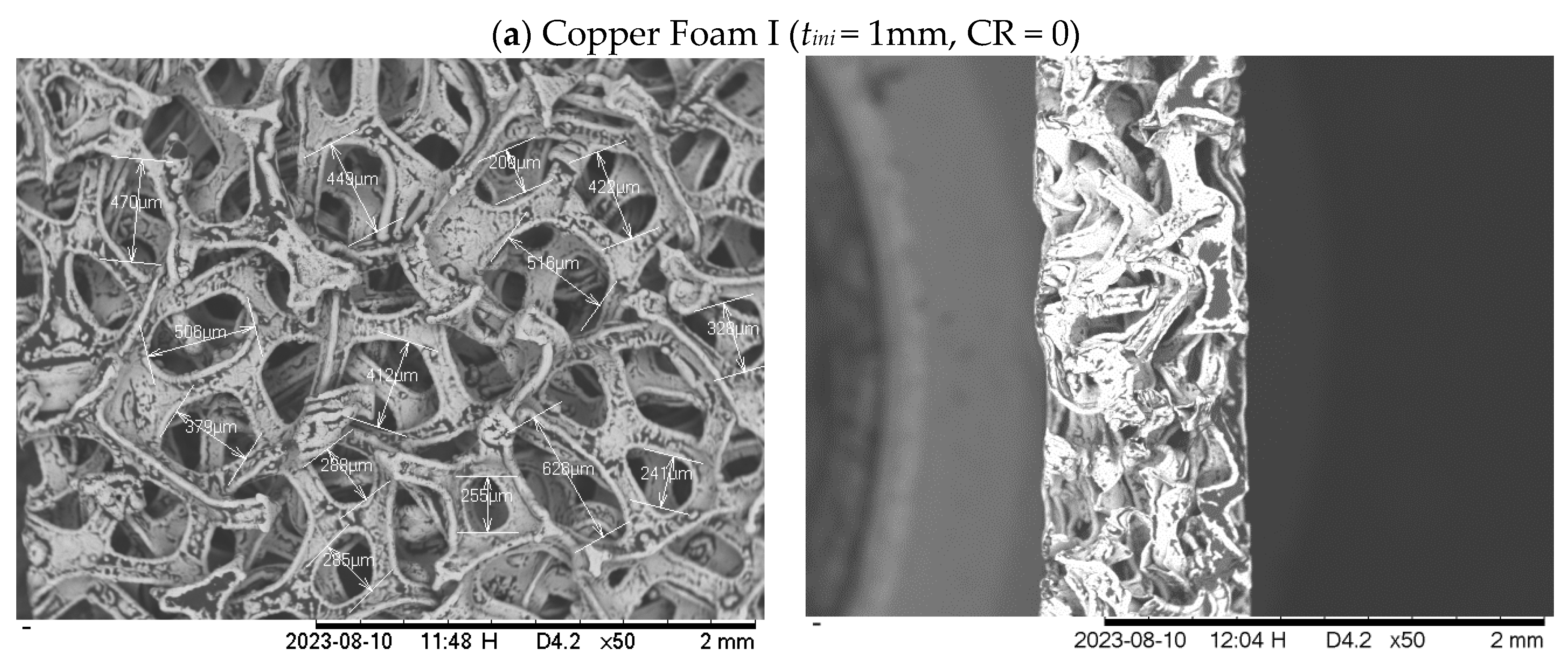
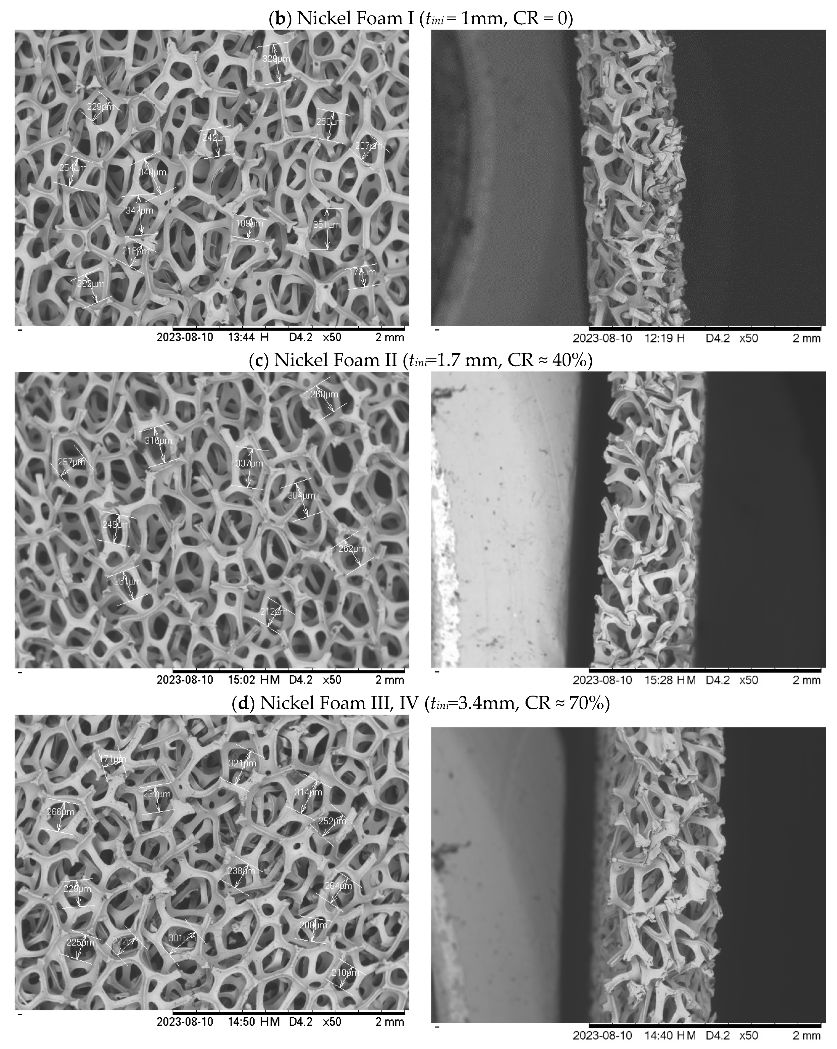
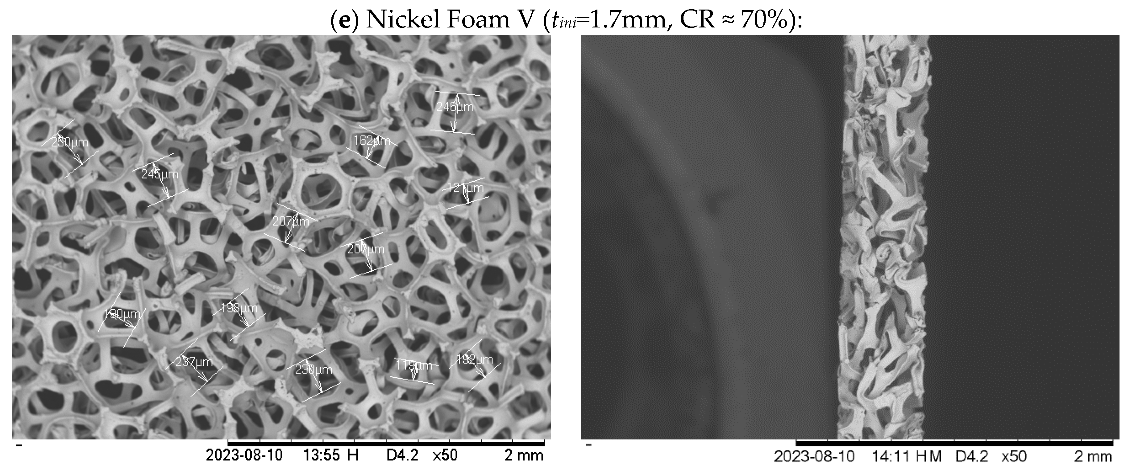
Figure 2.
PEFC single cell implemented in this study.
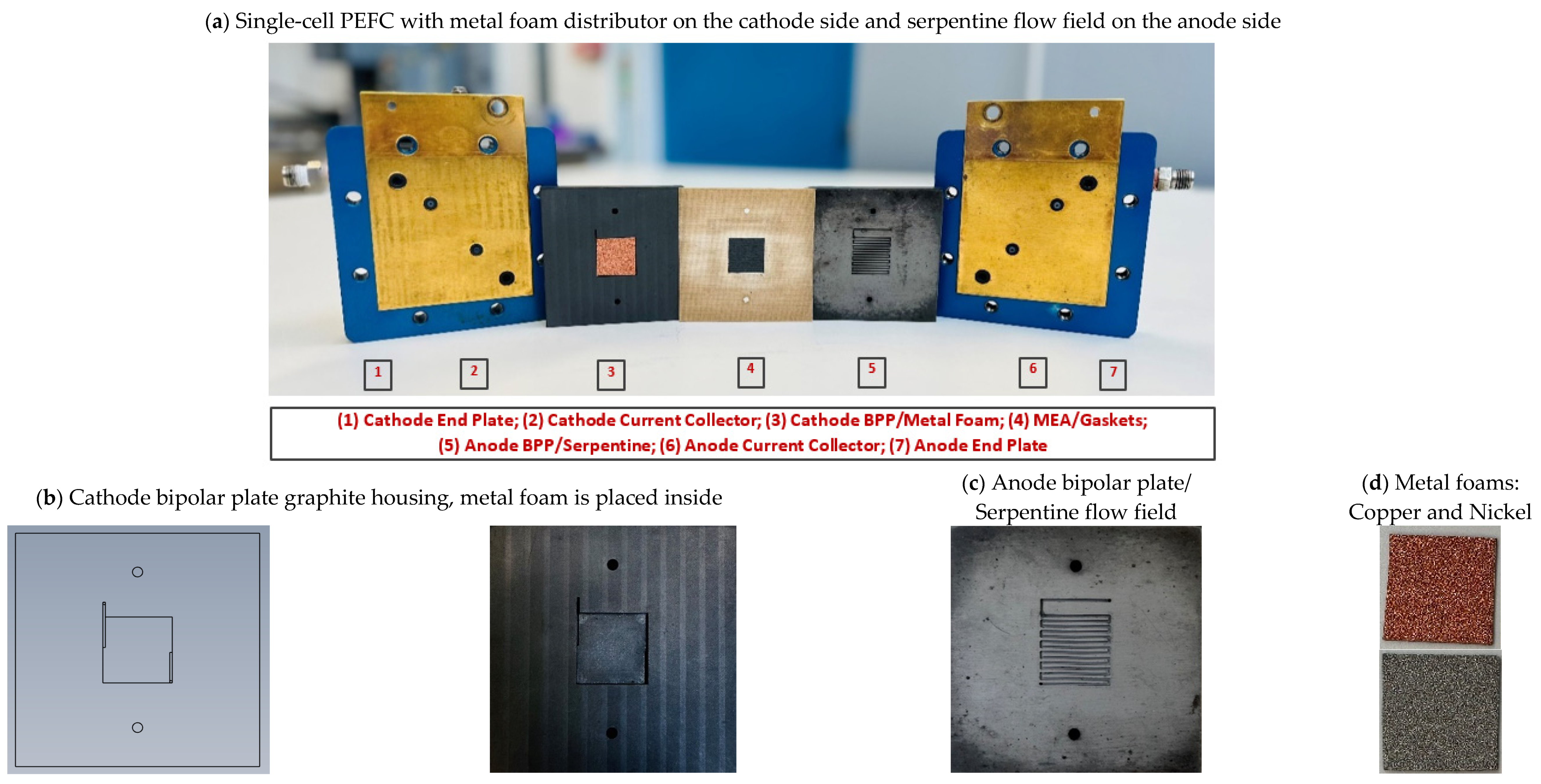
Figure 3.
Domain geometry and grid discretization implemented in the present study, with flow fields of conventional serpentine and metal foam.
Figure 3.
Domain geometry and grid discretization implemented in the present study, with flow fields of conventional serpentine and metal foam.
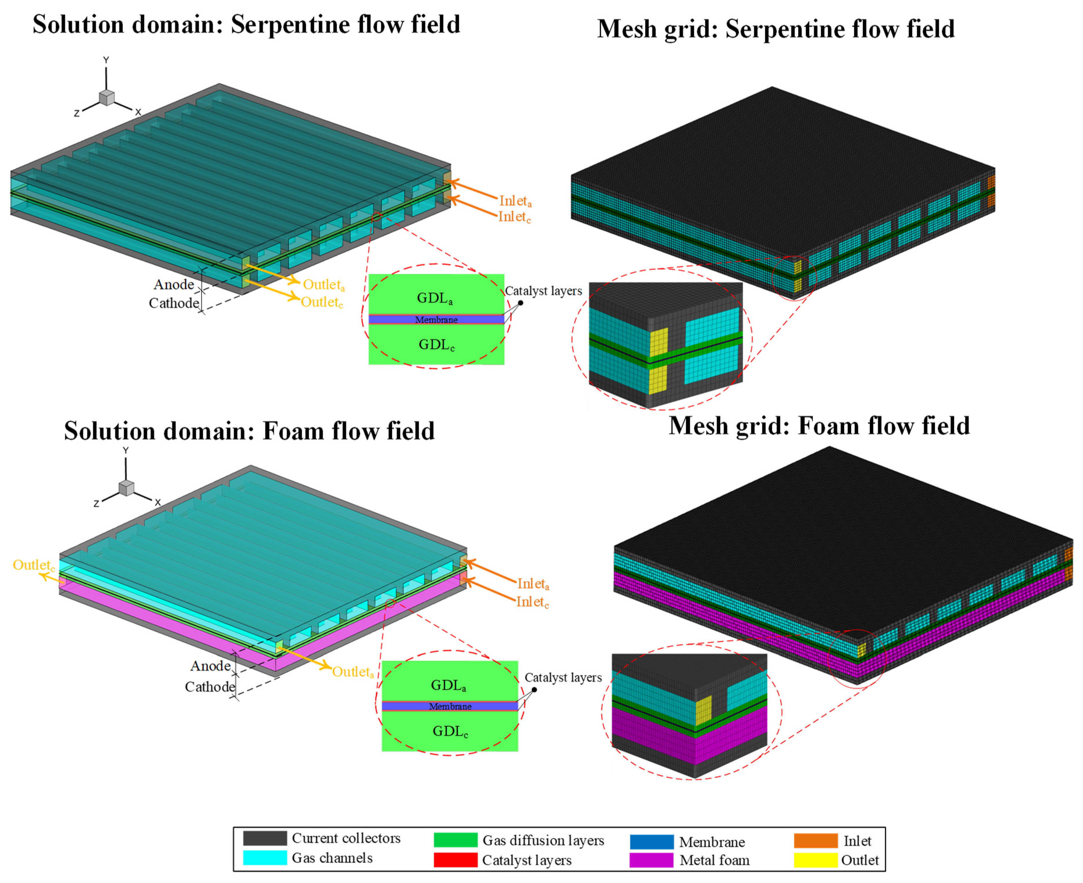
Figure 4.
The performance curves obtained from the experimental tests to compare the implementation of different metal foams on the cathode side; (a) Polarization curves and (b) Power density curves.
Figure 4.
The performance curves obtained from the experimental tests to compare the implementation of different metal foams on the cathode side; (a) Polarization curves and (b) Power density curves.
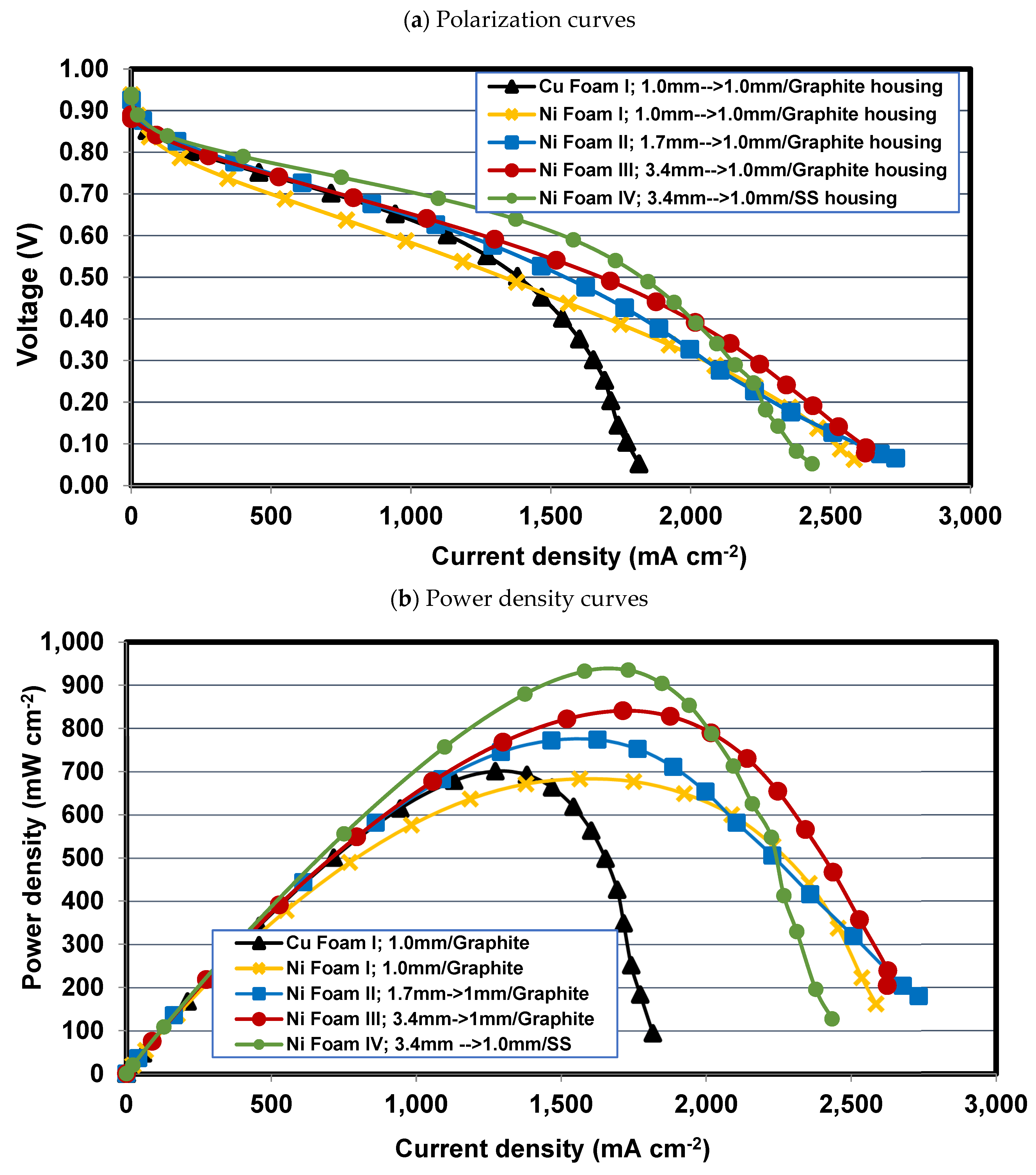
Figure 5.
The performance curves obtained from the experimental tests to compare the implementation of nickel foams (Foam IV-Ni and Foam V-Ni) with serpentine flow field on the cathode side; (a) Polarization curves, and (b) Power density curves.
Figure 5.
The performance curves obtained from the experimental tests to compare the implementation of nickel foams (Foam IV-Ni and Foam V-Ni) with serpentine flow field on the cathode side; (a) Polarization curves, and (b) Power density curves.
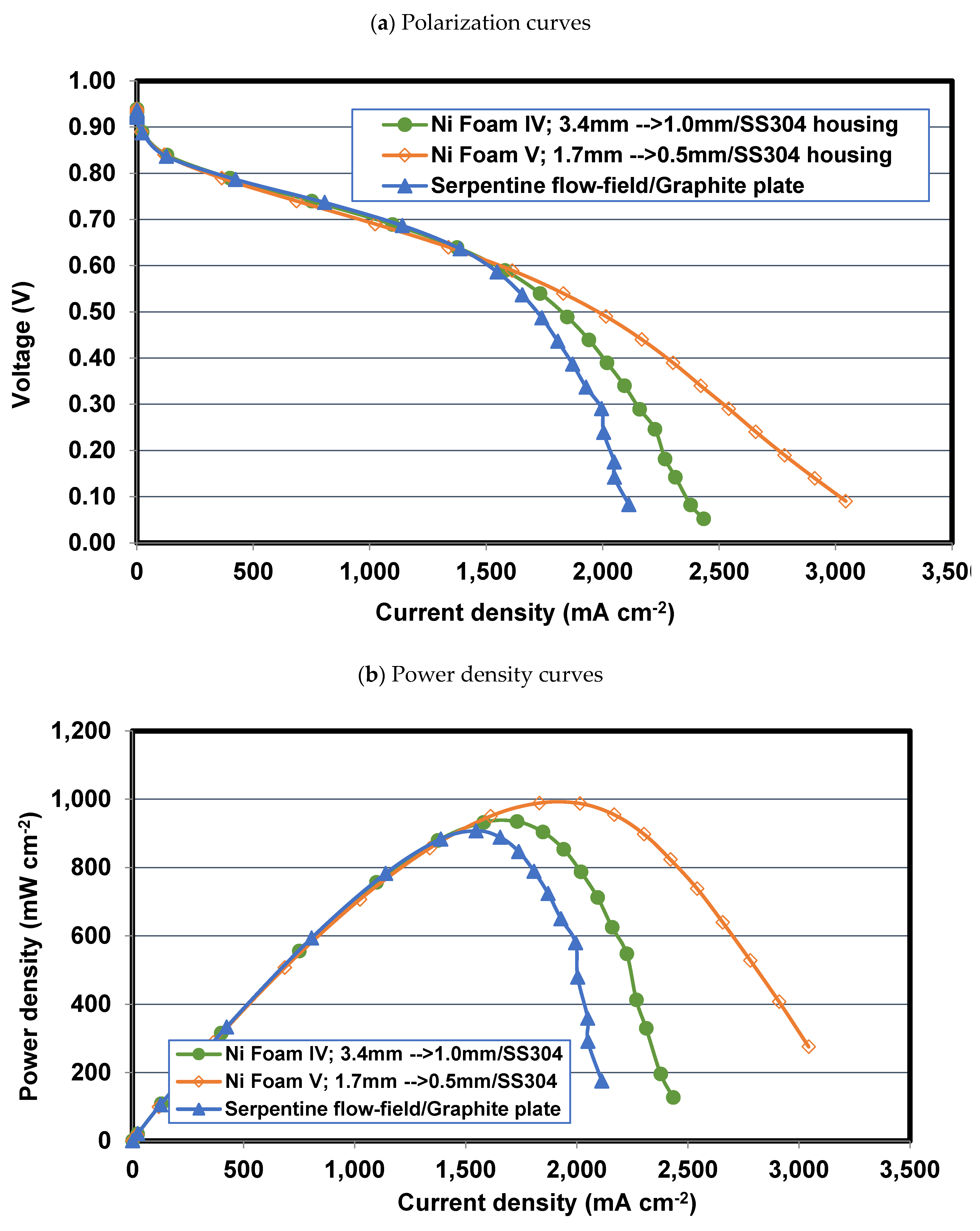
Figure 6.
EIS analysis of PEFC with Foams IV-Ni and V-Ni at (a) V = 0.7 V and (b) V = 0.4 V.
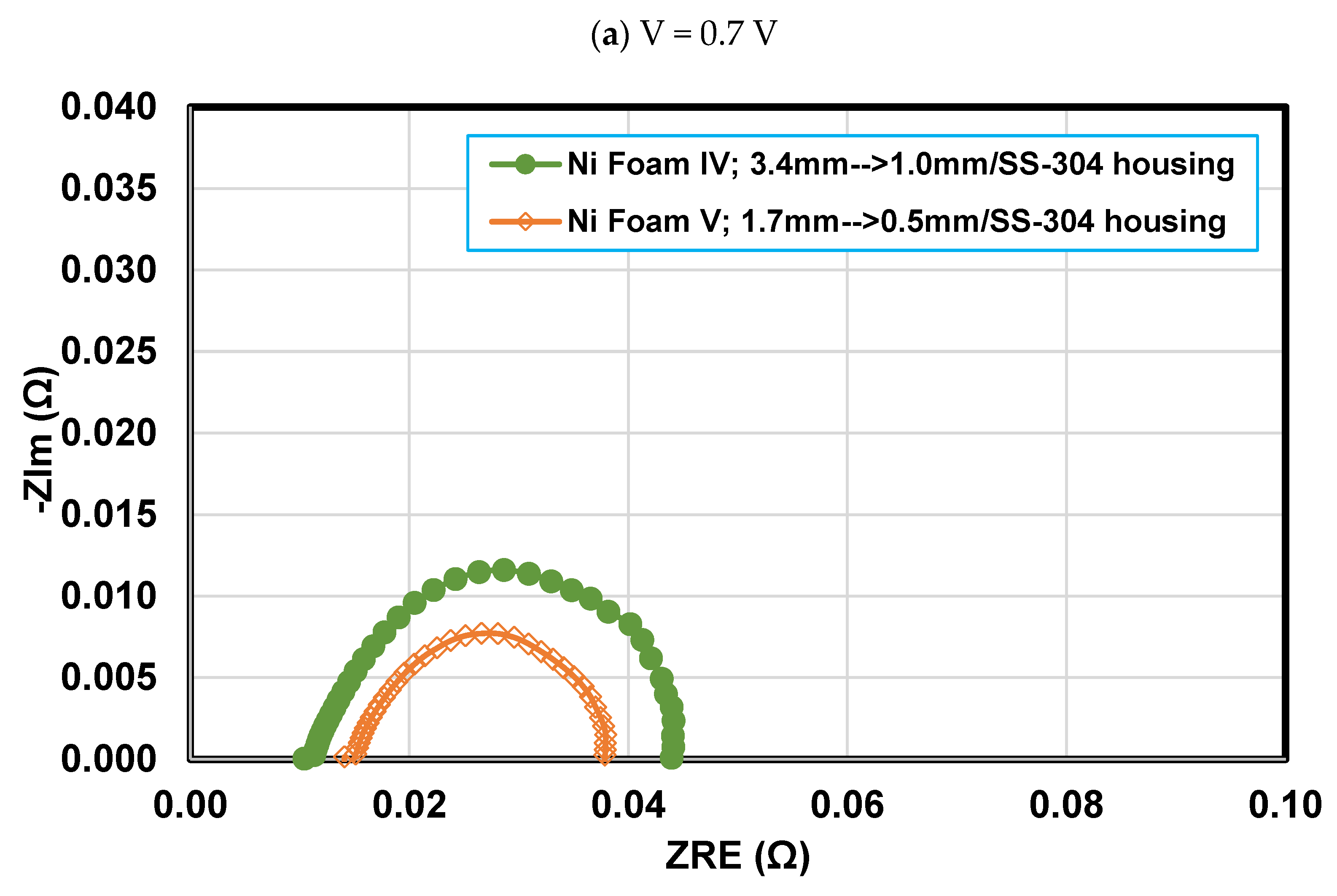
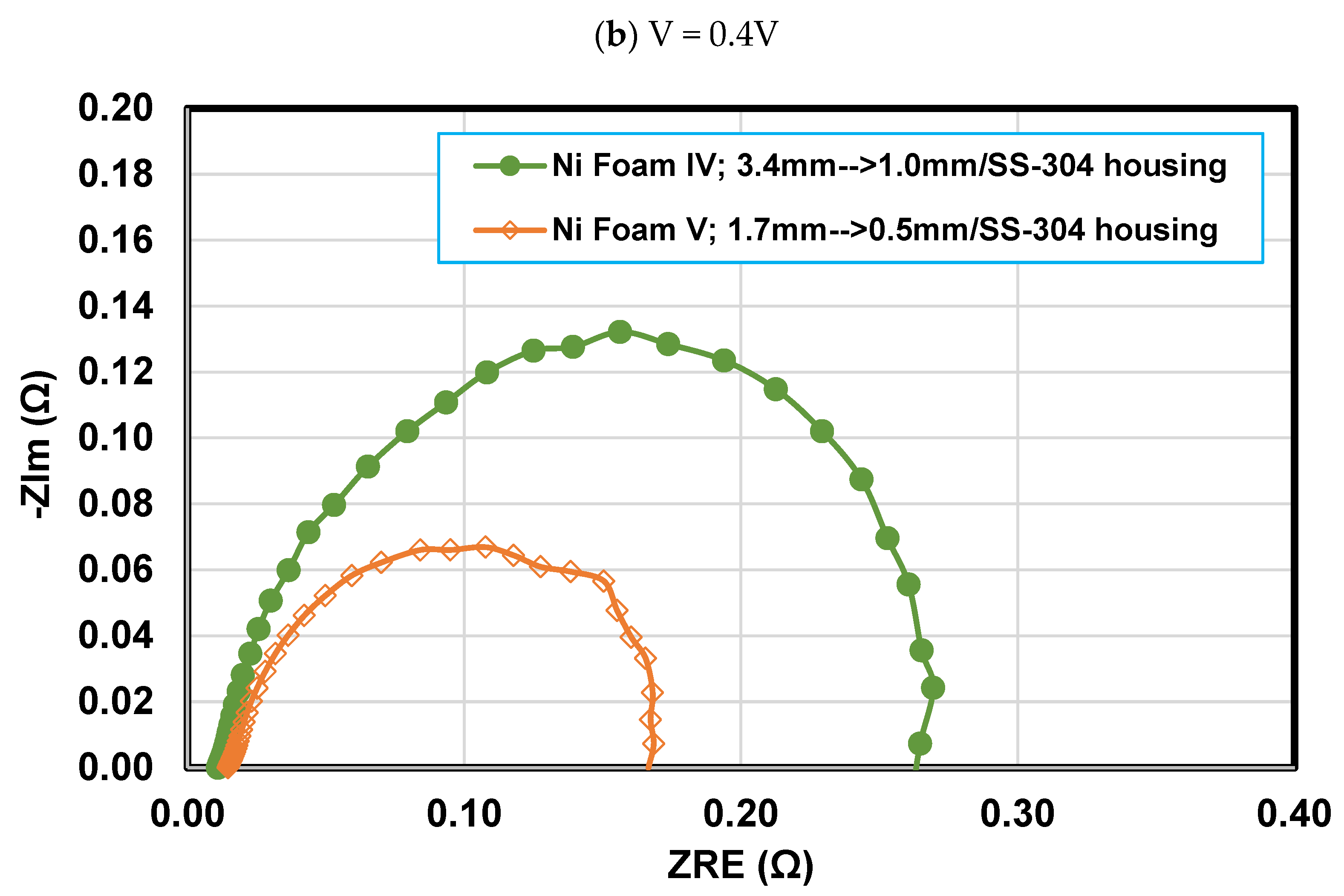
Figure 7.
Effect of relative humidity on polarization curve of PEFCs with Foams IV-Ni, V-Ni, and serpentine flow fields at (a) RH = 75%, (b) RH = 30%.
Figure 7.
Effect of relative humidity on polarization curve of PEFCs with Foams IV-Ni, V-Ni, and serpentine flow fields at (a) RH = 75%, (b) RH = 30%.
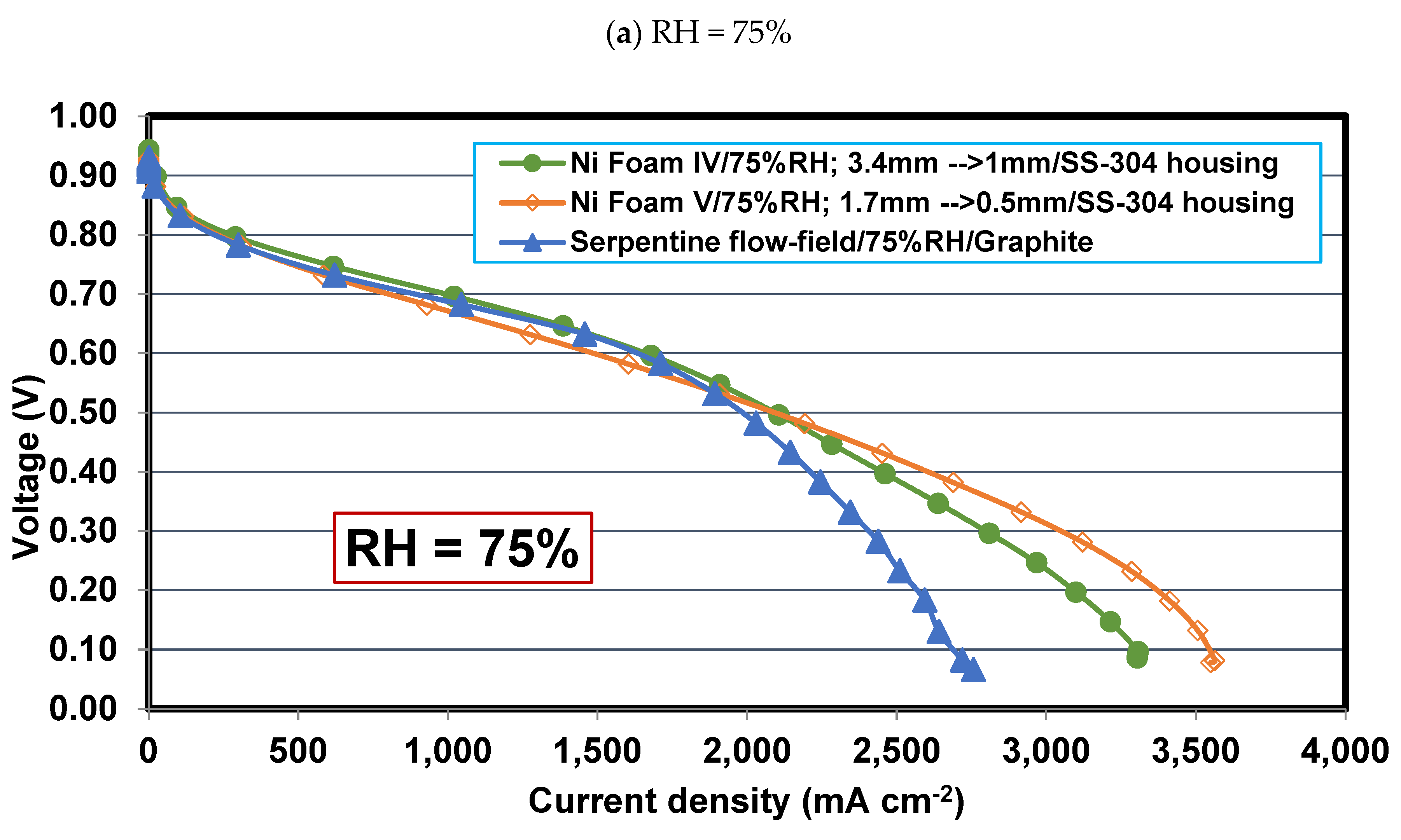
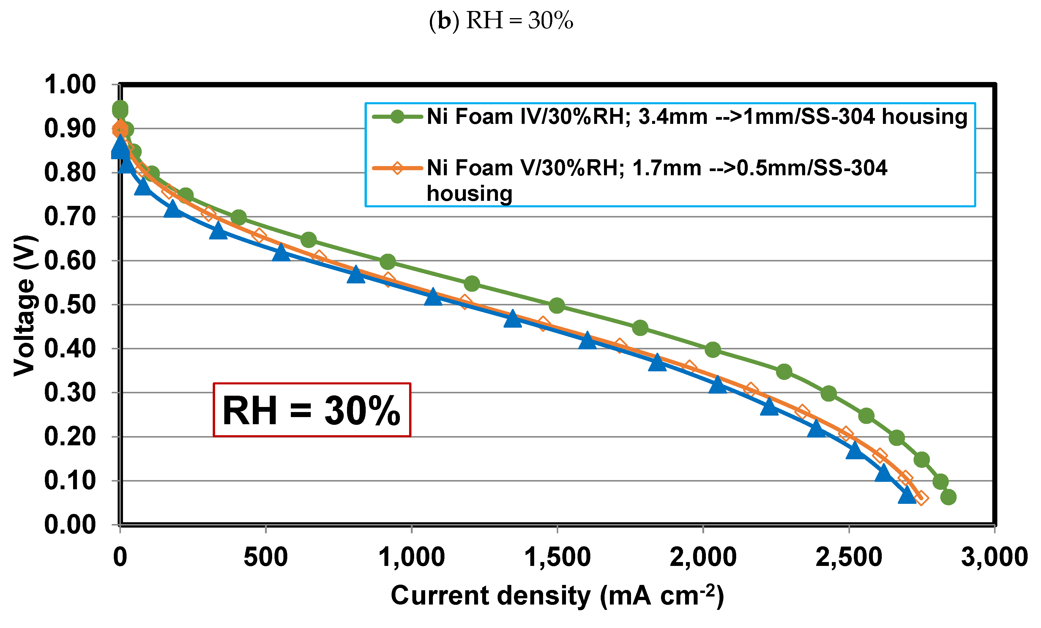
Figure 8.
Effect of relative humidity on power density curve of PEFCs with Foams IV-Ni, V-Ni, and serpentine flow fields at (a) RH = 75%, (b) RH = 30%.
Figure 8.
Effect of relative humidity on power density curve of PEFCs with Foams IV-Ni, V-Ni, and serpentine flow fields at (a) RH = 75%, (b) RH = 30%.
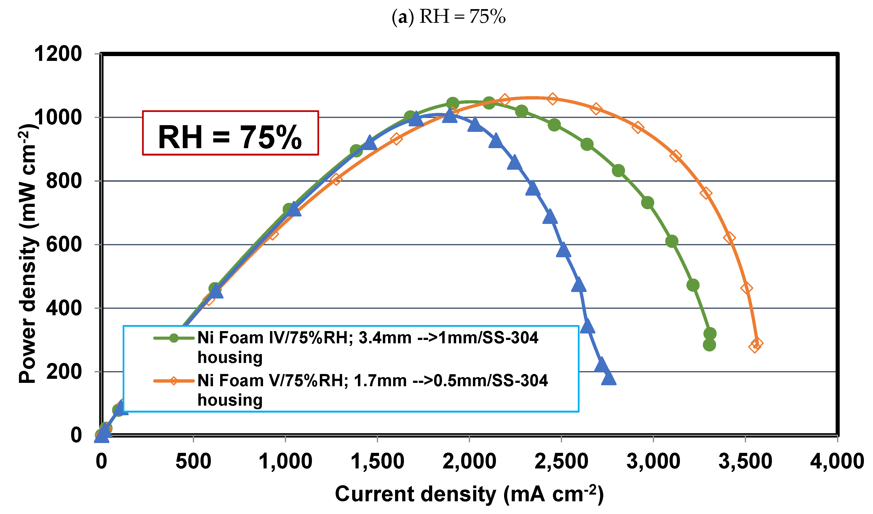
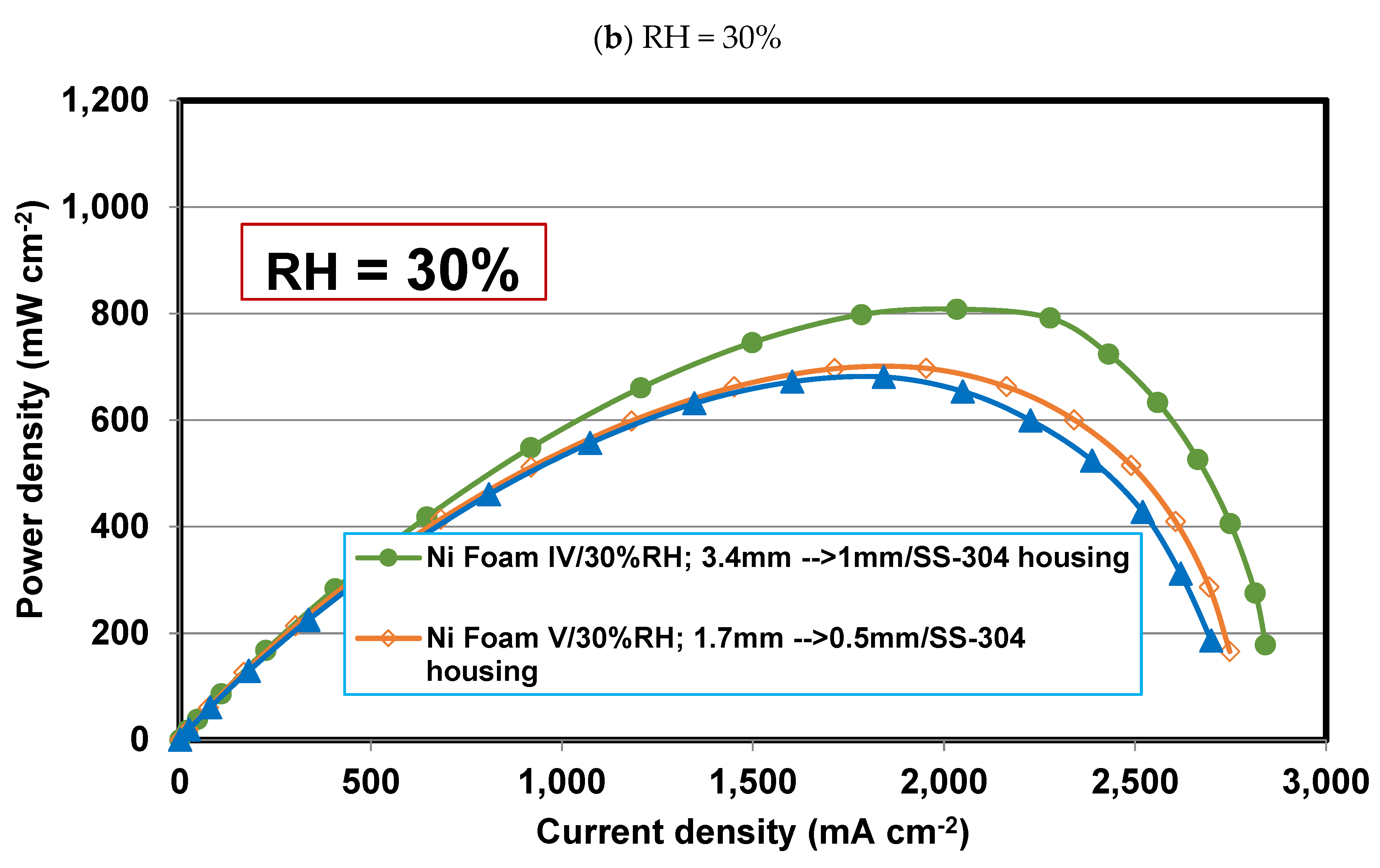
Figure 9.
The validation of the polarization curves obtained from the present experimental studies and numerical simulation for PEFCs with Foam V-Ni distributor and serpentine flow-field.
Figure 9.
The validation of the polarization curves obtained from the present experimental studies and numerical simulation for PEFCs with Foam V-Ni distributor and serpentine flow-field.
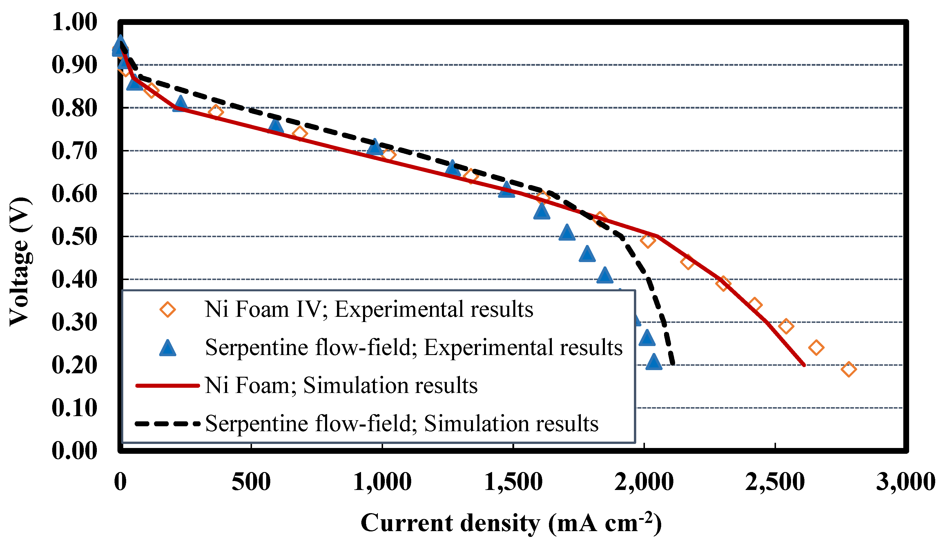
Figure 10.
Contours of oxygen mass fraction in the case of nickel Foam V flow field to analyze the uniformity of reactant; (a) along the mid-plane of cathode side metal foam/channel distributor, (b) along the mid-plane of the catalyst layer.
Figure 10.
Contours of oxygen mass fraction in the case of nickel Foam V flow field to analyze the uniformity of reactant; (a) along the mid-plane of cathode side metal foam/channel distributor, (b) along the mid-plane of the catalyst layer.
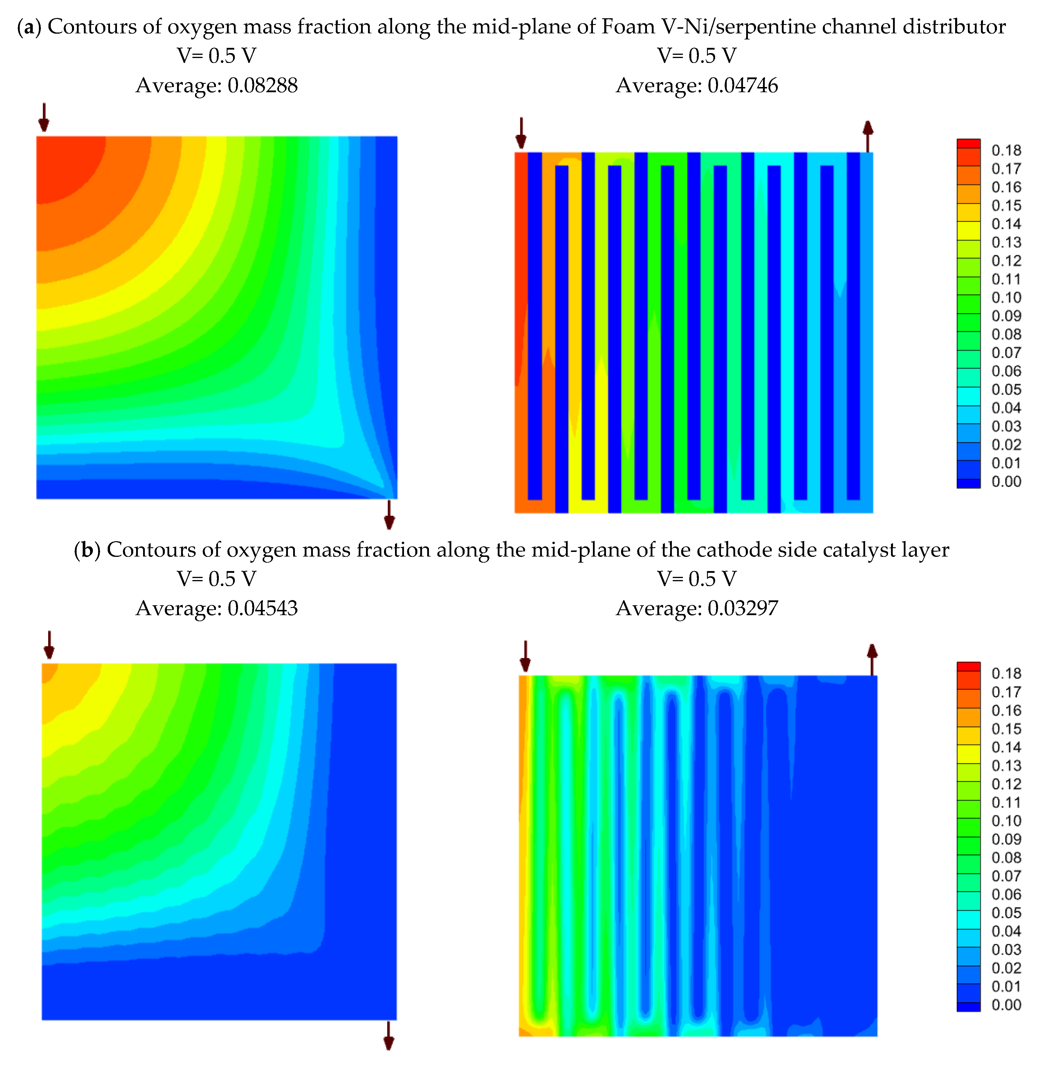
Figure 11.
Comparison of PEFC with foam and serpentine flow fields: (a) contours of current density along the mid-plane of cathode catalyst later; (b) contours of pressure along the mid-plane of Foam V-Ni/serpentine channel distributor.
Figure 11.
Comparison of PEFC with foam and serpentine flow fields: (a) contours of current density along the mid-plane of cathode catalyst later; (b) contours of pressure along the mid-plane of Foam V-Ni/serpentine channel distributor.
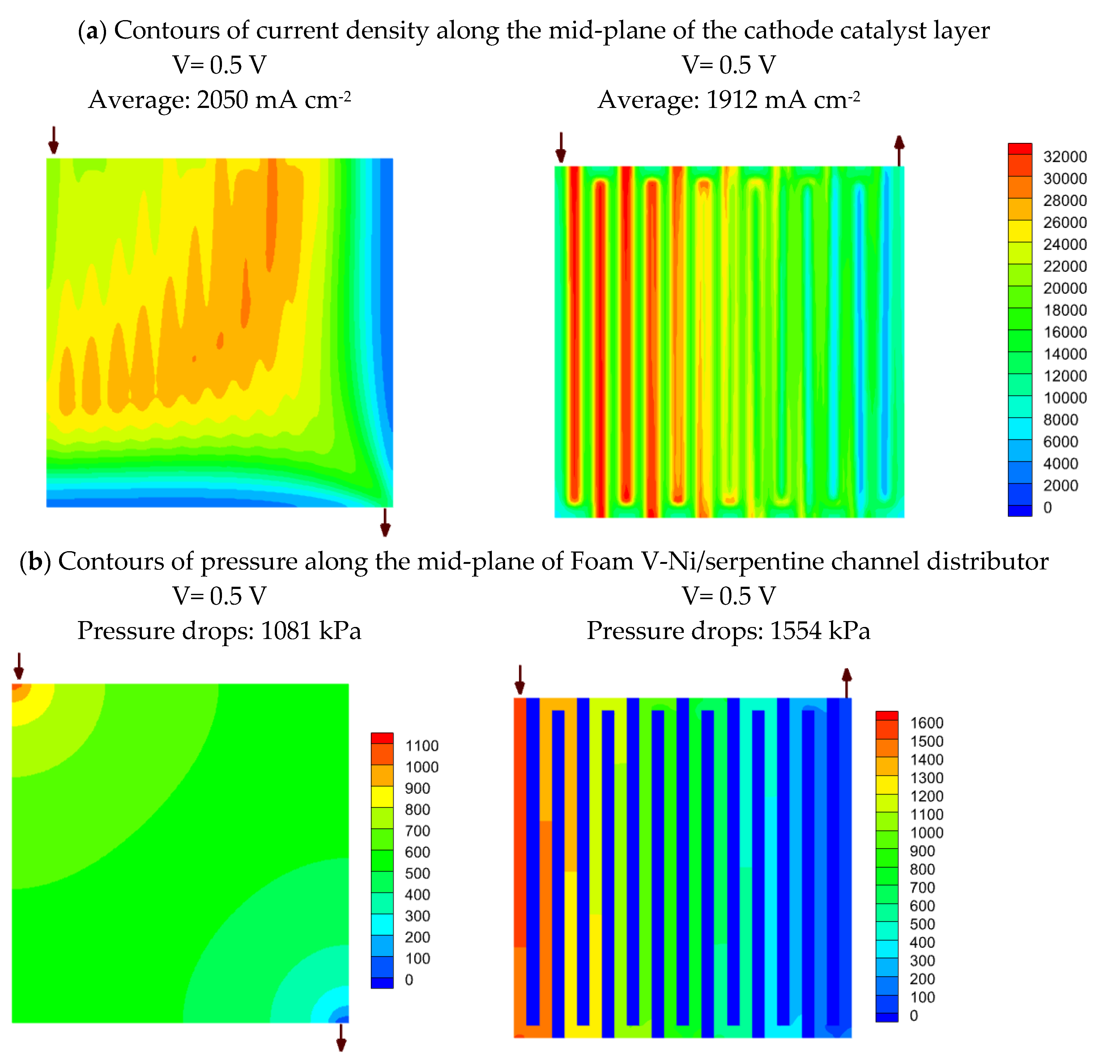
Figure 12.
Contours of oxygen mass fraction in the case nickel Foam V distributor for cell voltage of 0.6, 0.5, and 0.4 V; (a) along the mid-plane of Foam V-Ni distributor, (b) along the mid-plane of the cathode catalyst layer.
Figure 12.
Contours of oxygen mass fraction in the case nickel Foam V distributor for cell voltage of 0.6, 0.5, and 0.4 V; (a) along the mid-plane of Foam V-Ni distributor, (b) along the mid-plane of the cathode catalyst layer.
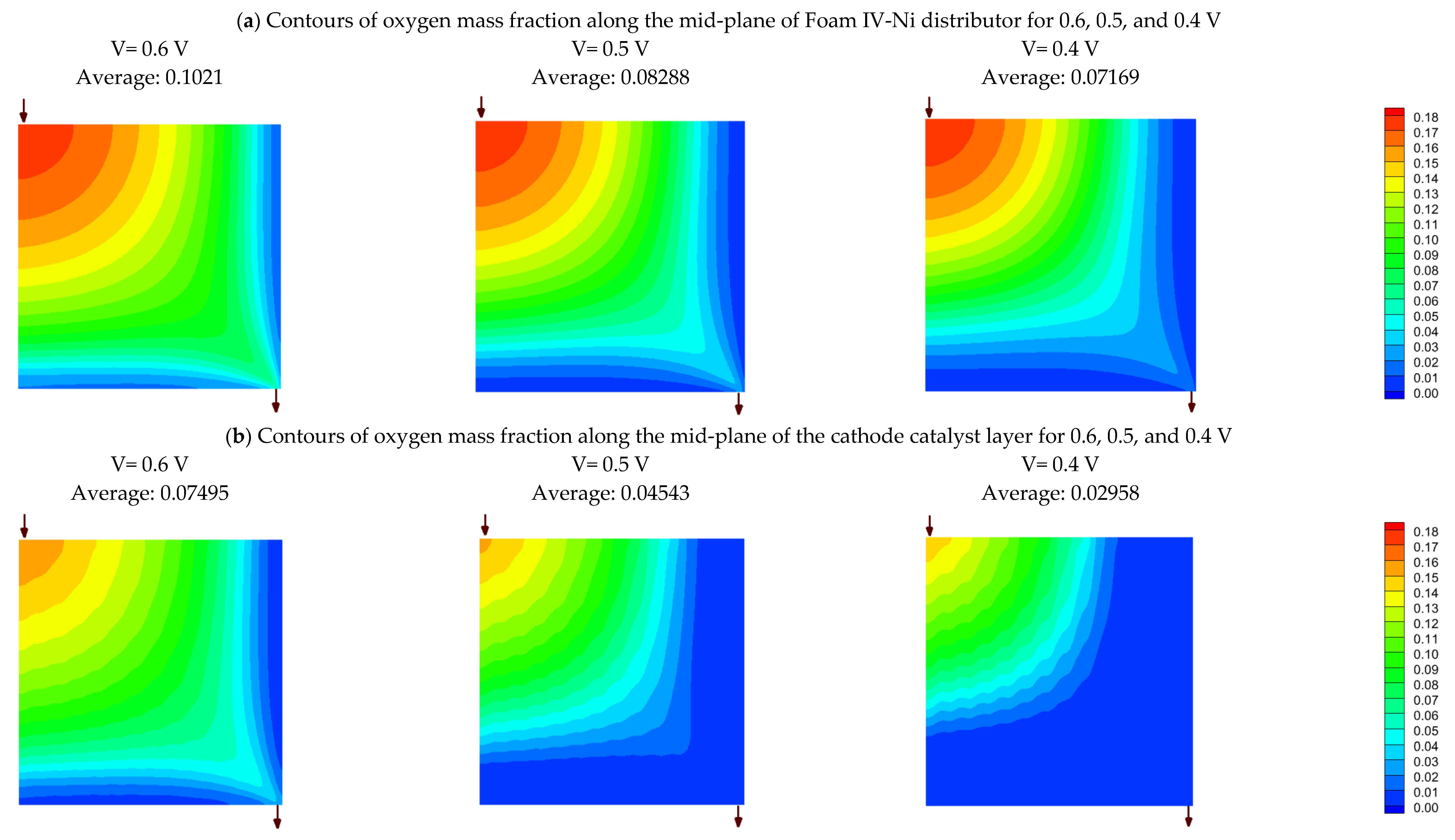

Table 1.
The designed metal foams were used in this study.
| Foam type | Material | Housing plate material | Initial thickness (mm) | Final thickness (mm) | CR (%) |
|---|---|---|---|---|---|
| Foam I-Cu | Copper | Graphite | 1 | 1 | 0 |
| Foam I-Ni | Nickel | Graphite | 1 | 1 | 0 |
| Foam II-Ni | Nickel | Graphite | 1.7 | 1 | 40 |
| Foam III-Ni | Nickel | Graphite | 3.4 | 1 | 70 |
| Foam IV-Ni | Nickel | SS-304 | 3.4 | 1 | 70 |
| Foam V-Ni | Nickel | SS-304 | 1.7 | 0.5 | 70 |
Table 2.
Governing equations.
| Mass | (1) | |
| Momentum |
where, the Forchheimer coefficient, , is only considered for metal foam and is vanished for all other porous layers. The effective porosity and permeability in porous layers are calculated as follows: |
(2) |
| Species |
where, the effective diffusivity is calculated as: |
(3) |
| Energy |
that, the effective thermal conductivity is calculated as: , where kl is the thermal conductivity of liquid water, and kg is the thermal conductivity of gas mixture which is calculated by the ideal-gas-mixing-law. |
(4) |
| electric charges | (5) | |
| Protonic charges |
where, the volumetric electrochemical reaction rate is considered by the Butler-Volmer relation: |
(6) |
| Liquid water |
where, the water saturation diffusivity (capillary diffusivity) is calculated by: , , in which is capillary pressure computed by the Leverett function: , where is liquid-gas surface tension, |
(7) |
| Dissolved-water |
where, the dissolved water diffusion coefficient is calculated by: |
(8) |
Table 3.
Summary of the cel’s geometrical, electrochemical, material/structural, and transport parameters; and operating conditions.
Table 3.
Summary of the cel’s geometrical, electrochemical, material/structural, and transport parameters; and operating conditions.
| Parameter | Symbol | Unit | Value |
|---|---|---|---|
| Geometrical | |||
| Active area | A | mm2 | |
| Flow-field configuration | a) Control sample: single serpentine channel for both anode and cathode electrodes b) Intervention group: single serpentine channel for anode and metal foam for cathode electrodes |
||
| Channel width | mm | 0.8 | |
| Channel height | mm | 1 | |
| Rib width | mm | 0.8 | |
| GDL thickness | µm | 200 | |
| Metal foam thickness | mm | 1 | |
| Catalyst layers (CL) thickness | µm | 15 | |
| Membrane thickness | µm | 25 | |
| Current collector thickness | mm | 0.5 | |
| Electrochemical | |||
| Open circuit voltage | V | 0.945 | |
| Active surface-to-volume ratio | m2 m-3 | 200,000 | |
| Anode ref. current density, | A m-2 | 500,000 | |
| Cathode ref. current density, | A m-2 | 5000 | |
| Anode concentration exponent | - | 0.5 | |
| Cathode concentration exponent | - | 1 | |
| Hydrogen ref. concentration, | kmol m-3 | 1 | |
| Oxygen ref. concentration, | kmol m-3 | 1 | |
| Anode exchange coefficient, | , | - | 0.85 |
| Cathode exchange coefficient, | , | - | 0.85 |
| Faraday constant | F | C mol-1 | 96,485.3 |
| Material/structural | |||
| Density of GDL, solid part of Foam, CL, Mem, CC |
, , , , |
kg m-3 | 2719 Cu: 8978/ Ni: 8900 2719 1980 2719 |
| Density of liquid water | kg m-3 | 998.2 | |
| Specific heat of GDL, solid part of Foam, CL, Mem, CC |
, , , , |
J kg-1 K-1 | 871 Cu: 381/ Ni:460.6 871 2000 871 |
| Equivalent weight of the membrane | EW | kg (kmol)-1 | 2100 |
| Porosity of GDL, Foam, CL |
, , |
- | 0.8 0.85 0.47 |
| Viscous resistance (inverse of permeability) of GDL, Foam, CL |
|
m-2 |
|
| Contact angle of GDL, Foam, CL (for water droplet) |
, , |
O | 92 145 92 |
| Inertial resistance of Foam | m-1 | 2100 | |
| Molar volume of water | m 3 mol -1 | ||
| Molar volume of membrane | m 3 mol -1 | ||
| Transport properties | |||
| Reference hydrogen diffusivity | m2 s-1 | ||
| Reference oxygen diffusivity | m2 s-1 | ||
| Reference vapor diffusivity | m2 s-1 | ||
| Hydrogen thermal conductivity | W m-1 K-1 | 0.1672 | |
| Oxygen thermal conductivity | W m-1 K-1 | 0.0246 | |
| Vapor thermal conductivity | W m-1 K-1 | 0.0261 | |
| Hydrogen viscosity | kg m-1 s-1 | ||
| Oxygen viscosity | kg m-1 s-1 | ||
| Vapor viscosity | kg m-1 s-1 | ||
| Liquid water viscosity | kg m-1 s-1 | ||
| Thermal conductivity of GDL, Foam, CL, Mem, CC, |
, , , |
W m-1 K-1 | 10 Cu: 387.6/ Ni: 91.74 10 2 100 |
| Electrical conductivity of GDL, Foam, CL, Mem, CC |
, , , , |
S m-1 | 5000 Cu: / Ni: 5000 |
| Operating Conditions | |||
| Relative humidity at anode/cathode inlets | , | % | 100 |
| Operating temperature | , | oC | 80 |
| Operating pressure | P | bar | 1 |
| Stoichiometry coefficient at anode/cathode inlets | , | 1.3, 1.5 |
Table 4.
Quantitative summary of the experimental tests.
| Flow field type | Limiting current density | Maximum power density | ||
|---|---|---|---|---|
| Value mA cm-2 |
Improve rate | Value mW cm-2 |
Improve rate | |
| Serpentine channels | 2140 | 1.00 | 901 | 1.00 |
| Foam I-Cu | 1820 | 0.85 | 701 | 0.78 |
| Foam I-Ni | 2580 | 1.21 | 684 | 0.76 |
| Foam II-Ni | 2710 | 1.27 | 774 | 0.86 |
| Foam III-Ni | 2620 | 1.22 | 841 | 0.93 |
| Foam IV-Ni | 2430 | 1.13 | 935 | 1.04 |
| Foam V-Ni | 3110 | 1.45 | 989 | 1.10 |
Disclaimer/Publisher’s Note: The statements, opinions and data contained in all publications are solely those of the individual author(s) and contributor(s) and not of MDPI and/or the editor(s). MDPI and/or the editor(s) disclaim responsibility for any injury to people or property resulting from any ideas, methods, instructions or products referred to in the content. |
© 2023 by the authors. Licensee MDPI, Basel, Switzerland. This article is an open access article distributed under the terms and conditions of the Creative Commons Attribution (CC BY) license (http://creativecommons.org/licenses/by/4.0/).
Copyright: This open access article is published under a Creative Commons CC BY 4.0 license, which permit the free download, distribution, and reuse, provided that the author and preprint are cited in any reuse.


