Submitted:
09 August 2023
Posted:
10 August 2023
You are already at the latest version
Abstract
Ionic gel electrolyte retains the characteristics of non-volatilization, non-flammability and outstanding electrochemical stability of ionic liquid, and shows good electrochemical performance combined with the excellent characteristics of different matrix materials, which is considered to be the best choice to achieve the high energy density and safety at the same time. In this paper, a flexible and self-healing ionic gel electrolyte is prepared by solvent-assisted method based on a zteric ion (ZI) copolymer. Abundant hydrogen bonds and synergistic interaction of ions in the electrolyte system endowed it with wonderful self-healing ability. The ionic conductivity of 9.06×10⁻⁴ S cm-1 at room temperature was achieved. Besides, the tLi+ was also increased to 0.312. The self-healing function of the ionic gel electrolyte ensured the long-term tolerance of the SHIGE. The capacity retention rate of the Li//LiFePO4 battery is 96% after 155 cycles at 0.1 C at 60 oC. This polymer electrolyte is expected to solve the problem of increasing polarization,which is caused by the low lithium ions migration number in ionic liquid electrolyte. And ultimately, it gives rise to a good rate performance.
Keywords:
flexible electrolyte
; flame-retardant
; self-healing
; gel electrolyte
; lithium metal batteries
1. Introduction
Lithium-ion batteries (LIB) are applied in a variety of sectors on a wide scale, including consumer electronics, electric vehicles, drones and aerospace, as consumers and businesses demand more for range, cost and safety[1,2]. However, lithium metal batteries have not been commercially applied until now. Because lithium metal as a negative electrode increases energy density and also brings serious safety risks[3,4,5], which is intimately bound up with the formation of lithium dendrites. The highly active lithium metal reacts with the aprotic solvent in the electrolyte to construct a solid electrolyte interface (SEI) layer[6,7]. The uniform and stable SEI can passivation the surface of the negative lithium electrode to avoid the continuation of the side reaction. However, the SEI film is usually of low strength and easily breaks due to the uneven deposition of lithium ions, thus exposing more nucleation sites to the electrolyte. In the convex part, due to the tip effect, it is easier to realize rapid deposition of lithium, thus forming dendritic dendrites[8,9].
To solve the problem, researchers have proposed various solutions. But as we all know that lithium-ion batteries have relied severely on electrolytes consisting of flammable organic solvents (carbonates and ethers) and poorly thermally stable lithium salts[10]. This type of electrolyte not only has a narrow electrochemical window, limited operating temperature, but also is prone to a number of safety problems, which will become a more serious issue in lithium metal batteries[11,12]. In addition, under extreme high or low temperature conditions, the charging and discharging performance of lithium-ion batteries are still a tremendous problem, which hinders the further development of lithium ion batteries[13].
In this case, the application of solid electrolytes not only can optimize the electrochemical performance and safety of next-generation lithium batteries, but also makes it’s possible to guarantee the application of lithium metal anode to maximize energy density[14,15]. However, the actual performance of solid-state Li-metal batteries is hampered by high resistance between lithium dendrites and metal electrodes/solid-state electrolytes or grain boundaries, which is limiting the practical application of solid-state electrolytes. With the intention of mending the safety hazards of terrible room temperature ionic conductivity of solid polymer electrolytes, poor mechanical strength and thermal stability of gel electrolytes (organic solvents as plasticizers) [16], researchers have developed polymer matrix based ionic gel electrolytes (IGE). It has good flexibility, suitable strength and retains the characteristics of non-combustible and non-volatile ionic liquid, which can effectively enhance the safety of lithium metal battery[17,18].
Ionic liquids (ILs), consisted of organic cations and organic/inorganic anions, can melt at temperatures below 100 °C or even at room temperature. They can maintain liquid over a wide temperature range and have non-flammability, non-volatility, high thermal stability[19]. The most important is that it possesses a wide electrochemical stability window. When ILs which are absorbed and fixed to different kinds of substrates as the main ionic conductors are typically used to prepare IGE, which has many advantages over pure IL. First, the rapid dissociation of charge carriers and the anchoring of anions enables faster transport of lithium ions, which helps to improve the rate performance. Secondly, due to the hysteretic glass transition and higher thermal decomposition temperature, it has a wider operating temperature range. At the same time, its solid properties give it high mechanical strength and leakage resistance, as well as other unique functions such as the adjustment of ion deposition behavior of lithium metal cathode.
Copolymers have attracted wide attention as substrates for ionic gel electrolytes because of their ability to bind corresponding homopolymers. Researchers can design the structure of different types of block copolymers to obtain polymer substrates with different physical and chemical nature. Among them, zteric ion (ZI) segment is an "inner salt" that binds a pair of cations and anions together through covalent bonding. It possessed equal amounts of positive and negative charges, and shows a massive molecular dipole moment. Prominent ion-dipole interaction has the ability to boost the dissociation of lithium salt[20,21].
In this paper, the copolymer network, Imidazole-based ionic liquid (EMIMTFSI) and LiTFSI were combined by solvent-assisted physical mixing method to prepare a flexible, flame-retardant and self-healing ionic gel electrolyte (SHIGE). The abundant hydrogen bonds in SHIGE system and the synergistic interaction between ZI segment and ionic pair of ionic liquid give it good self-healing ability. At the same time, the ionic liquid in the SHIGE system assists to decrease the crystallinity of the polymer and promote the movement of the polymer segments, and has a higher safety than traditional liquid electrolyte. ZI monomer can promote the dissociation of lithium salt and improve the transport of Li+ in the electrolyte system. Its uniform arrangement can effectively regulate the distribution of lithium flux to achieve homogeneous deposition of Li+ and avoid the composition of lithium dendrites. The above unique properties give the ZI copolymer-based SHIGE remarkable electrochemical performance, and it is expected to be a promising flexible electrolyte material.
2. Materials and Methods
2.1. Materials
Poly(propylene glycol) bis(2-aminopropyl ether) (PEA, D-400, average Mn ~400), 2-isocyanatoethyl methacrylate (IEM,98%), Poly(vinylidene fluoride) (PVDF), 2,2,2-trifluoroethanol (TFEA, 99.5%), [2-(Methacryloyloxy)ethyl]dimethyl-(3-sulfopropyl) (SBMA, 97%), Poly(vinylidene fluoride) (PVDF, Mw ~180000), 1-ethyl-3-methylimidazolium bis(trifluoromethylsulfonyl)imide (EMIM TFSI, 99%) and bis(trifluoromethane)sulfonimide lithium salt (LiTFSI, 99%) are purchased from Aladdin. 1-Methyl-2-pyrrolidinone (NMP) and hydroxyacetone (HPLC) are purchased from Sinopharm. Azobisisobutyronitrile (AIBN, 99%) is purchased from Macklin. Lithium iron(II) phosphate (LFP) and acetylene black (AB) are purchased from Canrd.
2.2. Synthesis of the D-IEM
0.6 mmol D-400 and 2-isocyanatoethyl methacrylate (IEM) were firstly dissolved in 10 mL hydroxyacetone, and then the former was added to the latter drop by drop under the ice bath. The termination of the amino groups was realized through the high reactivity of the isocyanate group and the amino group. Nitrogen blowing removes excess hydroxyacetone solvent to obtain D-IEM with double bonds at both ends.
2.3. Synthesis of bisexual ionic copolymers
The obtained D-IEM was dissolved in 80 mL TFEA with 0.48 mmol amphoteric ion monomer [2-(Methacryloyloxy)ethyl]dimethyl-(3-sulfopropyl) (SBMA), and 2 wt % (monomer base) AIBN was added. After heating and stirring under nitrogen protection at 65 °C for 24 h, a light yellow viscous solution was obtained, which was exposed to air to terminate the polymerization. Subsequently, the reaction solution was added to deionized water to precipitate the resulting bisexual ionic copolymer, which was redissolved in a small amount of TFEA to remove impurities, and then reprecipitated in deionized water. Finally, the polymer sample was vacuum lyophilized.
2.4. Synthesis of self-healing ionic gel electrolyte(SHIGE)
1 M LiTFSI was dissolved in ionic liquid (EMIM TFSI) by magnetic stirring in a glove box (H2O<0.1 ppm, O2<0.1 ppm) overnight until the solution was homogeneous and clear. A certain amount of the polymer sample was dissolved in TFEA, which was then added to the ionic liquid dissolved in lithium salt, and the solution was injected into the PTFE template and dried at 60 °C for 6 h after stirring, and further dried at 100 °C for 12 h under vacuum to obtain homogeneous SHIGE membranes.
2.5. Characterization of ionic gel electrolyte
The surface morphology of SHIGE membranes and lithium anode before and after cycling were observed using a field emission scanning electron microscope (FESEM, MAIA3 LMH equipped with energy dispersive X-ray spectroscopy (EDS)). Fourier transform infrared spectrometer (FT-IR, Bruker VERTEX70) was used to test the D-400, IEM and the synthesized D-IEM with a wave number of 650-4000 cm-1, and the test mode was selected as attenuated total reflection (ATR). The thermogravimetric curves were obtained using a simultaneous thermal analyzer (NETZSCH-STA449F5) in a nitrogen atmosphere at a ramp rate of 10 °C min-1 from room temperature to 500°C.
2.6. Electrochemical measurements
Electrochemical impedance spectroscopy (EIS) was performed using a Pristine electrochemical workstation with SHIGE as the electrolyte and two stainless steel electrodes assembled into a CR 2016 type button cell with a temperature interval from 20 °C to 80 °C and a frequency range from 105 Hz to 10-1 Hz for interfacial impedance measurements. Ionic conductivity σ of the SHIGE membrane can be calculated from Equation 1:
where L is the thickness of the quasi-solid electrolyte sheet, R is the measured impedance, and S is the contact area between the quasi-solid electrolyte and the stainless steel electrode.
A CR 2016 type button cell, assembled with a stainless steel electrode as the working electrode and a lithium metal anode electrode as the counter electrode, was used to perform linear scanning voltammetry (LSV) measurements of SHIGE at 60 °C with a scan rate of 1 mV s-1 in the potential interval of 0 V to 6 V.
Lithium symmetric cells of type CR 2016, which was mounted with lithium metal anode and SHIGE, were tested for AC impedance and constant potential polarization at 60 °C. Li-ion migration number can be calculated by equation 2 as followed:
where ΔV is the direct current polarization voltage (10 mV), I0 and IS are the initial and steady currents during polarization, respectively, and R0 and Rs are the impedances before and after polarization, respectively.
Further the lithium ion conductivity of SHIGE can be calculated from the following equations 3:
where σLi+ is the lithium ion conductivity, σ is the overall SHIGE conductivity, and tLi+ is the lithium ion mobility number.
2.7. Self-healing and fire-resistant test
After cutting the SHIGE membrane into four pieces, the degree of healing was observed at different time and recorded by optical photographs. The flame retardant performance were tested by directly igniting the SHIGE samples with a lighter for 1 s and recording the burning phenomena by optical photographs.
2.8. Lithium battery manufacturing and performance
LiFePO4 (80 wt%), carbon black (10 wt%) and PVDF (10 wt%) were mixed well and then stirred with appropriate amount of 1-methyl-2-pyrrolidinone (NMP) dropwise. Subsequently, the slurry was coated on aluminum foil and dried in a vacuum oven at 110°C for 12 h. LiFePO4/SHSPE/Li (CR2016) button-type cells were assembled using LiFePO4, SHSPE and lithium metal anode in an argon-filled glove box (H2O < 0.1 ppm, O2 < 0.1 ppm). Constant-current charge/discharge and cycling performance were tested at 25 °C using a battery test system (Neware Electronic Co., Ltd.) at 4 to 2 V potential.
3. Results and discuss
As shown in Figure 1a, It is clear to see the process of preparing SHIGE-GPE by radical polymerization. In the beginning, the addition of the terminal radicals of D-400 and IEM in acetone under ice bath obtain the precursor D-IEM, and then the precursor D-IEM is dissolved together with SBMA in TFEA. Furthermore, AIBN is used to initiate polymerization to construct the ultimate cross-linked network SHIGE at 65 oC. The SEM image of the SHIGE membrane (Figure 1b) demonstrates the homogeneity and flatness of its surface, which endows it the ability to make good contact with the electrode interface. Furthermore, the uniform distribution of elements such as C, N, O, F and S in the corresponding EDS spectra (Figure 1c-g) proves the successful preparation of the polymer SHIGE with homogeneous dispersion of components, which is crucial for the Li+ migration during the assembly and charging/discharging of Li-ion batteries.
Figure 1.
(a) Graphical synthetic route of the SHIGE (b) SEM image and (c-g) Corresponding EDS surface scan elemental distribution spectra of SHIGE membrane surface (h)D-400,IEM and D-IEM (i) FT-IR spectra of D-IEM,SBMA,EMIMTFSI and SHIGE (j) The schematic of the SHIGE internal simplified structure.
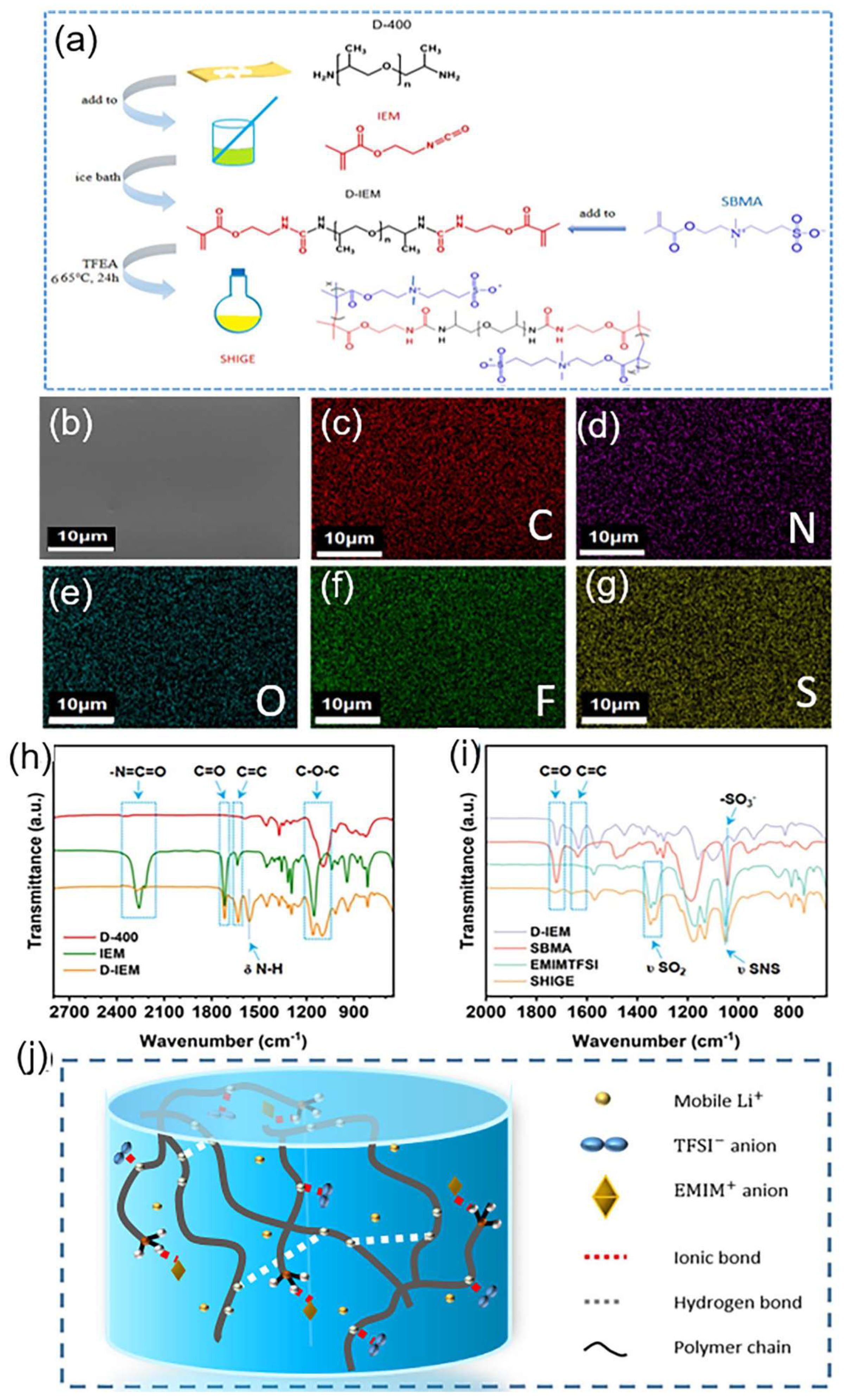
Figure 1h shows the FT-IR test results of D-400, IEM, and the synthesized D-IEM. The absorption peak at 2260 cm-1 of the wave number corresponds to the isocyanate group of IEM, while in D-IEM this peak has almost disappeared, proving the successful reaction of the -N=C=O group of IEM with the amino group on D-400[22]. The absorption peak located at 1718 cm-1 represents the stretching vibration of the C=O bond, while the corresponding D-IEM wave number at 1632 cm-1 proves the successful retention of the C=C double bond. The absorption peaks at wave numbers 1100 cm-1 and 1150 cm-1 are on account of the stretching vibration of the C-O-C bond, while the absorption peak located at 1560 cm-1 is due to the deformation vibration of the seconal amide N-H bond on the D-IEM.
Figure 1i shows the FT-IR spectra of SHIGE membrane. The absorption peaks located at 1720 cm-1 and 1632 cm-1 in accord with the C=O and C=C bonds of the monomer, respectively, and it can be seen that SHIGE has no absorption peak for the C=C bond, which proves the complete polymerization of the monomer. The absorption peak located at 1043 cm-1 is attributed to the stretching vibration of the -SO3- group on the SBMA monomer molecule, and the spectrum of SHIGE also exhibits a subordinate peak corresponding to the -SO3- group. Meanwhile, the peaks of SHIGE at 1330 cm-1 and 1347 cm-1 consistent with the out-of-plane stretching vibration and in-plane stretching vibration of -SO2--, respectively. Combined with the strong peak of the asymmetric stretching vibration of S-N-S at 1051 cm-1 of the wave number, strongly demonstrate that the gelation of TFSI- containing-ionic liquids. The successful preparation of the cross-linked network is highly favorable for constructing the continuous transmission path of lithium ion flux (Figure 1j).
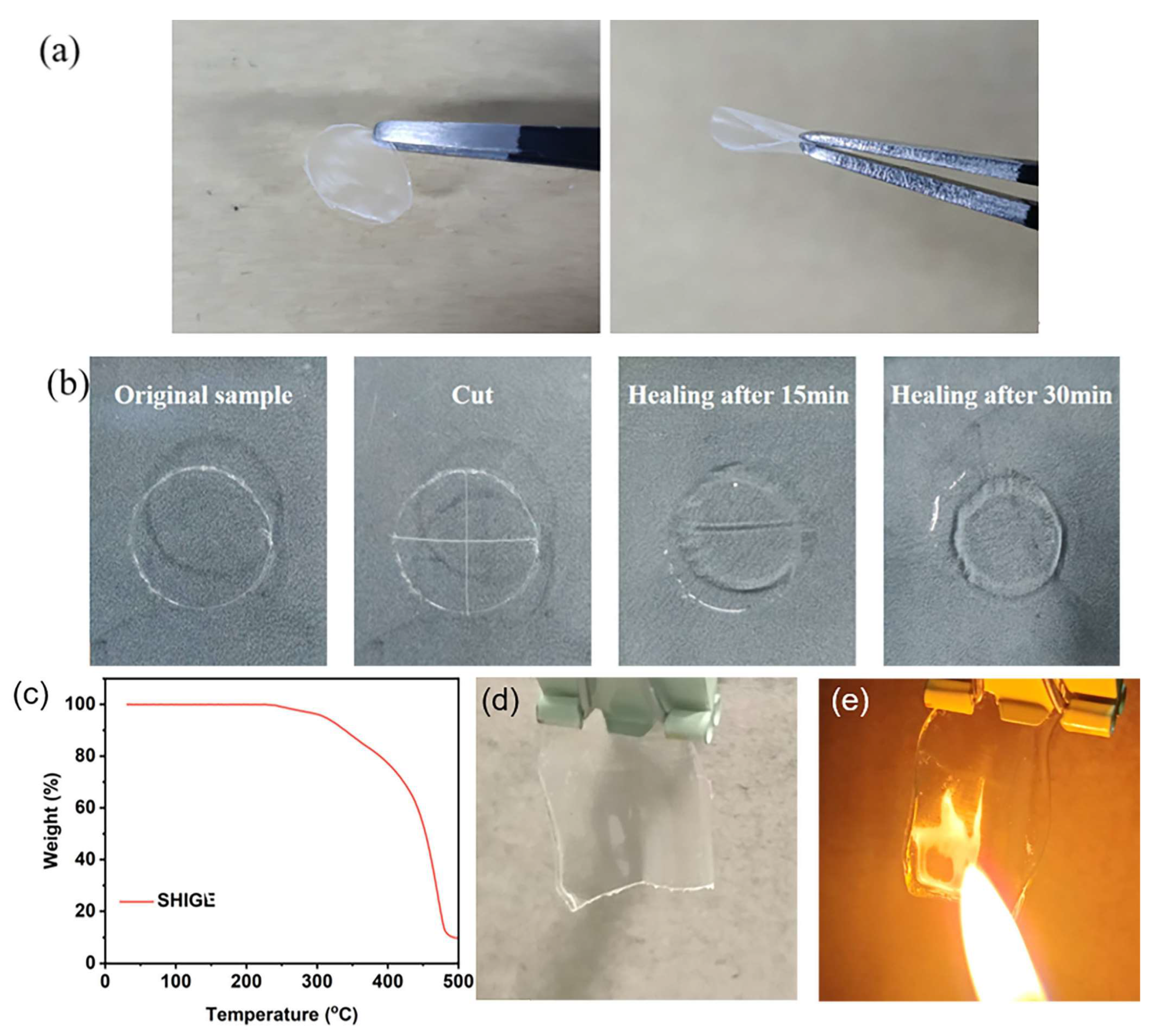
As shown in Figure 2a, SHIGE membrane exhibits transparent and homogeneous capability and possesses impressive flexibility. The self-healing ability of SHIGE membrane was inspected, and Figure 2b shows the degree of self-healing at different time. After being cut into four pieces, SHIGE membranes achieved partial self-healing within 15 min at 60 °C, with only shallow dents on the section. And after 30 min of self-healing, the scratches on the surface of SHIGE membrane completely disappeared and returned to the initial state, confirming its splendid self-healing ability, which is closely related to the structure of the polymer backbone. Firstly, the abundant hydrogen bonds on the backbone have good self-healing ability. And secondly, the sulfonic acid radical groups on the backbone also show strong inter-ionic interaction force in the high ionic concentration environment, the SHIGE membrane achieves excellent self-healing function which is combined with the accelerated movement of polymer chain segments at 60 °C.
It is well known that liquid electrolytes are prone to leakage, which can further lead to safety incidents such as battery combustion or explosion accidents[23]. However, ionic gel electrolytes that use ionic liquids as plasticizers can avoid the risks to a great extent compared with the use of organic solvents. To evaluate the safety of SHIGE membrane in battery applications,the thermogravimetric curves obtained using a simultaneous thermal analyzer are shown in Figure 2c. It can be seen that the samples only start to decompose at a temperature of 230 °C, confirming that SHIGE membrane can maintain excellent thermal stability over an extremely wide temperature range, demonstrating the excellent ionic liquid retention capability of SHIGE membrane even under high temperature conditions. What’s more, fire-resistant test was also conducted on SHIGE. It can be plain to see in the Figure 2d-e that after 1 seconds on fire, the SHIGE still maintains its original shape, proving that it has excellent flame retardance. This property provides a higher safety guarantee for lithium batteries in the charge and discharge process.
Figure 1.
Optical photograph of (a) Flexible SHIGE membrane (b) Self-healing process of SHIGE membrane at 60 °C. (c) TGA curve of SHIGE. Digital photographs of SHIGE (d) Exposed to a flame (e) After fire.
Figure 1.
Optical photograph of (a) Flexible SHIGE membrane (b) Self-healing process of SHIGE membrane at 60 °C. (c) TGA curve of SHIGE. Digital photographs of SHIGE (d) Exposed to a flame (e) After fire.
A high ionic conductivity has the capacity to weaken the internal resistance of the batteries and boost their rate capabilities. As shown in Figure 3a-b, the EIS spectrum of SHIGE membrane demonstrates its impedance profile at different temperatures, which in turn reflects its ability to transport lithium ions at distinct temperatures. It can be seen that the impedance of SHIGE decreases with increasing temperature and exhibits high ionic conductivity over an extensive temperature range, with 7.78 × 10⁻⁴ S cm-1 at 20 °C, 9.06 × 10⁻⁴ S cm-1 at 25 °C, and 2.62 × 10⁻³ S cm-1 at 60 °C. This elevation originates from the acceleration of the polymer chain segment movement by increasing temperature. Meanwhile, the unique structure of the amphoteric monomer SBMA allows it to disrupt the ionic environment consisting of lithium ions and anions in the system and promotes the dissociation of lithium salts, enhancing the migration of lithium ions ultimately. In addition, the interactions between Li+ and the abundant ether-oxygen bonds and O=C-O in SHIGE along with the liquid phase in the free volume render efficient conduction paths. What’s more, the combination of these factors thus makes SHIGE membrane possess high room temperature ionic conductivity, which ensures good ion transport capability and lays the foundation for its application in lithium secondary batteries.
Figure 1.
SHIGE(a) EIS profiles at 25 to 80 °C and (b) the corresponding variable temperature conductivity. (c) LVS curve. Lithium ion mobility number of (d) pure ionic liquids EMIMTFSI and (e) SHIGE. SEM images of (f) the constant current cycling curve and (g) the enlarged plot of the voltage curve near 70~80 h of the Li|SHIGE|Li symmetric cell. The surface SEM image of (h) fresh lithium metal and (i) recovered lithium anode after 100 h of cycling of the Li|SHIGE|Li symmetric cell.
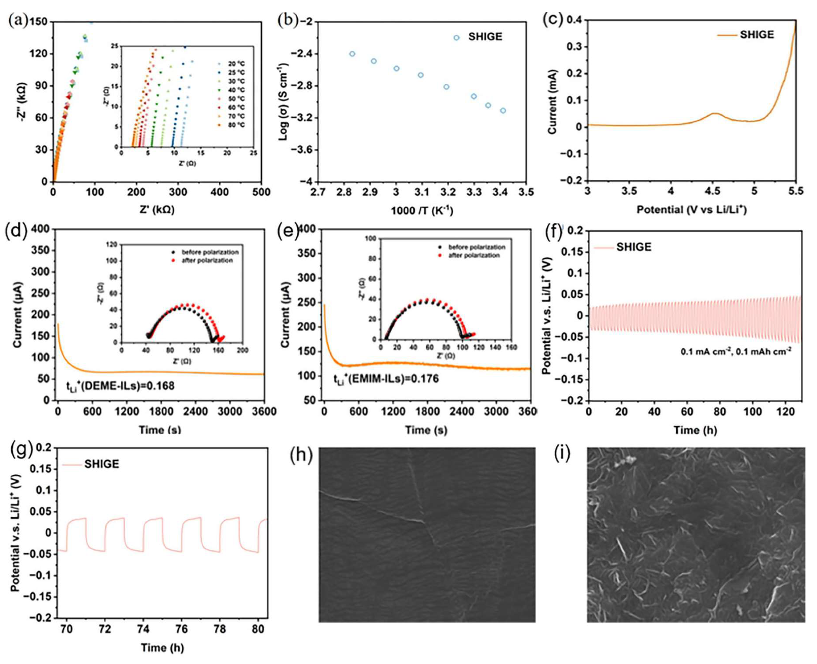
To verify the electrochemical stability of SHIGE membrane to the lithium metal anode, a Li|SHIGE|SS cell was assembled to measure the LSV curve of SHIGE together with the result as shown in Figure 3c. It can be seen that SHIGE membrane has a wide electrochemical window, and its decomposition potential exceeds 4.2 V. Its decomposition peak located around 4.5 V may be caused by the decomposition of TFEA solvent remaining in the SHIGE membrane during the preparation process, but the decomposition potential exceeding 4.2 V can ensure its matching with the lithium iron phosphate cathode and avoid the decomposition of SHIGE membrane.
For Li-ion batteries, achieving a higher Li+ mobility number of the electrolyte is a precondition for high power output capability and an essential approach to suppress superfluous anion migration[24]. A lower Li+ mobility number tends to induce the growth of Li dendrites by generating space charge fields on the anode surface. On the contrary, a high Li+ transfer number is highly competent in shrinking the concentration polarization during charging-discharging. The Li|SHIGE|Li symmetric cell was assembled and tested as shown in Figure 3d-e. Moreover, we further calculated by Equation 2 that the lithium ion migration number of pure ionic liquid EMIMTFSI is 0.150. On the contrary, the SHIGE membrane can reach 0.312, which is double compared to the pure ionic liquid electrolyte. This huge improvement stems from the construction of the polymeric three-dimensional (3D) network in SHIGE, which inhibits the movement of ionic liquid anions with large volume in the system and provides a channel for rapid Li+ transport. On the other hand, it may also be attributed to the effective improvement of lithium salt dissociation and uniform regulation of lithium flux by the amphoteric ionic monomer SBMA homogeneous arranged on the polymeric 3D skeleton[25]. The lithium ion conductivity of SHIGE membrane was further calculated from Equation 3 to be 2.83 × 10⁻⁴ S cm-1, indicating the good lithium ion transport properties of SHIGE membrane.
To investigate the suitability of SHIGE membrane with Li-metal battery, we assembled the Li|SHIGE|Li symmetric cells and did a test at 60 °C with a current density of 0.1 mA cm-2 for constant current cycling. Figure 3f-g show the polarization voltage curve of the Li|SHIGE|Li cell. The initial polarization potential of Li|SHIGE|Li cell is only 20 mV at a current density of 0.1 mA cm-2, and the overpotential is still maintained within 50 mV after 130 h of cycling. On top of that, the voltage curves during charging and discharging are relatively smooth, indicating the good compatibility of SHIGE membrane with lithium metal anode and its promising application in lithium metal batteries.
The SEM images in Figure 3h-i demonstrate that the lithium metal anode with SHIGE membrane assembled generates dense and uniform passivated SEI films on its surfaces after cycling. It is apparent that no deposition of dead lithium or growth of lithium dendrites can be seen on the surface of the lithium metal anode after 100 h of cycling compared with the fresh one. This is closely related to the effective regulation of the homogeneous deposition and charge distribution of Li+ in the system by the amphoteric monomer SBMA.
The electrochemical window of SHIGE above 4.2 V ensures its suitability with LiFePO4 cathode, so SHIGE and LFP are assembled to form LFP|SHIGE|Li battery for a long time cycle charge/discharge test to demonstrate its performance in solid-state Li-metal batteries, including the capacity decay and cycle life performance of the battery. The charge/discharge voltage cutoff range of the battery is set from 2.0 V to 4.0 V.
Figure 4a shows the cycling curve of the LFP|SHIGE|Li cell at 60 °C at a multiplicity of 0.1 C. It can be seen that the initial specific capacity of the cell is 128 mAh g-1 and then the specific capacity drops to 120 mAh g-1 within a few cycles, which may be due to insufficient contact between the SHIGE and the electrodes. After 10 cycles, the specific capacity of the cell rose rapidly and gradually recovers to 130 mAh g-1 and remains constant for the next 80 cycles, before the specific capacity slowly decreases and remains 123 mAh g-1 after 155 cycles, and the polarization of the cell does not increase sharply during the cycle (Figure 4b), showing outstanding specific capacity at 0.1 C magnification cycle stability. However, the first cycle charge/discharge efficiency of SHIGE is only 78%, but the Coulomb efficiency increases to 96% after 155 cycles, which is not satisfactory, probably due to the fact that the TFEA solvent molecules is not completely removed during the preparation of the SHIGE membrane and thus decomposes during the charge/discharge process.
Figure 1.
LFP|SHIGE|Li battery cycle curve at 60 °C (a) 0.1 C and (b) corresponding charge/discharge curve; (c) 0.5 C and (d) corresponding charge/discharge curve.
Figure 1.
LFP|SHIGE|Li battery cycle curve at 60 °C (a) 0.1 C and (b) corresponding charge/discharge curve; (c) 0.5 C and (d) corresponding charge/discharge curve.
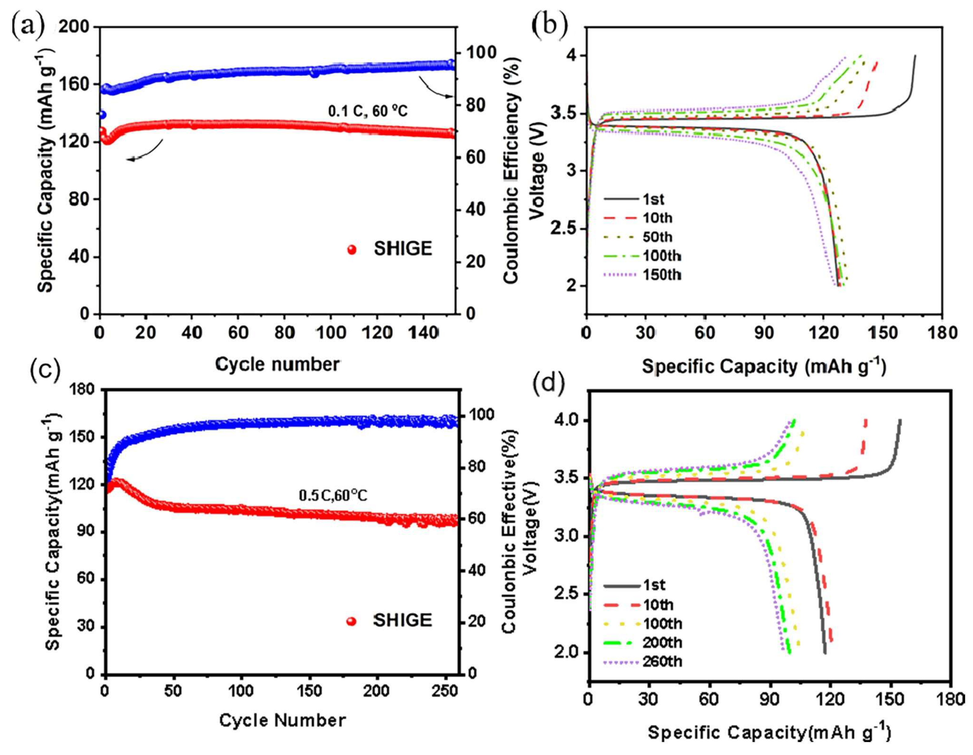
Cyclic charging and discharging performance of the LFP|SHIGE|Li battery was investigated at a higher current density, as shown in Figure 4c. The LFP battery reaches an initial specific capacity of 117.3 mAh g-1 at a multiplication rate of 0.5 C and 60 oC. However, there is a mild increase in the specific capacity within the next 15 cycles, which corresponds to the activation process of the battery. From Figure 4d, it is clear that there is no obvious polarization of the cell in the first 10 cycles. During the subsequent cycles, it can be seen that the rate of increase of the cell polarization slows down, and thus the specific capacity of the cell decays more slowly during the subsequent 210 cycles, from 105.94 mAh g-1 in the 50th cycle to 96.81 mAh g-1 in the 260th cycle. Apart from that, the initial Coulombic efficiency of the cell is only 75.9% due to the effect of the residual solvent molecules in the SHIGE membrane, which grows after ten cycles. It grows to 90% after a dozen cycles and follows the cycling process slowly, but eventually growing to 98% after 150 cycles.
4. Conclusions
In summary, a flexible and self-healing ionic gel electrolyte based on a zteric ion (ZI) copolymer is successfully obtained by free radical polymerization. The uniform distribution of zwitterionic segments on the skeleton can accelerate the dissociation of lithium salt and effectively enhance the lithium ion conductivity. The ionic conductivity can reach 2.62×10⁻³ S cm-1 along with high ion migration number (0.312) of SHIGE at 60°C. In addition, SHIGE with extraordinary flexibility and self-healing ability is capable of crucially refining the long-term tolerance of electrolytes. The assembled LFP/SHIGE/Li cells have a capacity retention rate of 96% after 155 charge and discharge cycles at 0.1C and 82.5% after 260 cycles at 0.5C. The experimental results show that the prepared SHIGE has good electrochemical performance, which provides a feasible idea for the design and development of electrolytes.
Author Contributions
Conceptualization, W.C. and M.L.; validation, Y.Y., W.T. and M.L.; investigation, W.C., X.G. and F.H.; resources, J.G. and X.T.; writing—original draft preparation, W.C.; writing—review and editing, W.C., Z.W. and M.L. All authors have read and agreed to the published version of the manuscript.
Funding
Financial support from the Natural Science Foundation of China (grant no. 21978231), International Science and Technology Cooperation Program of Shaanxi Province--Key project (grant no. 2022KWZ-08) and the Natural Science Foundation of Jiangsu Province, China (grant no. SBK2020021757). We thank the Instrumental Analysis Center of Xi’an Jiaotong University for material characterizations.
Data Availability Statement
Data supporting the findings of this study are available from the corresponding author upon reasonable request.
Conflicts of Interest
The authors declare no conflict of interest.
References
- Fan, E.; et al. Sustainable Recycling Technology for Li-Ion Batteries and Beyond: Challenges and Future Prospects. Chemical Reviews 2020, 120, 7020–7063. [Google Scholar] [CrossRef] [PubMed]
- Kim, T.; et al. Lithium-ion batteries: outlook on present, future, and hybridized technologies. Journal of Materials Chemistry A 2019, 7, 2942–2964. [Google Scholar] [CrossRef]
- Tian, X.; et al. Design Strategies of Safe Electrolytes for Preventing Thermal Runaway in Lithium Ion Batteries. Chemistry of Materials 2020, 32, 9821–9848. [Google Scholar] [CrossRef]
- Feng, X.; et al. Thermal runaway mechanism of lithium ion battery for electric vehicles: A review. Energy Storage Materials 2018, 10, 246–267. [Google Scholar] [CrossRef]
- Mu, L.; et al. Oxygen Release Induced Chemomechanical Breakdown of Layered Cathode Materials. Nano Letters 2018, 18, 3241–3249. [Google Scholar] [CrossRef]
- Aurbach, D.; et al. A short review of failure mechanisms of lithium metal and lithiated graphite anodes in liquid electrolyte solutions. Solid State Ionics 2002, 148, 405–416. [Google Scholar] [CrossRef]
- Wu, Z.; et al. A Metal–Organic Framework Based Quasi-Solid-State Electrolyte Enabling Continuous Ion Transport for High-Safety and High-Energy-Density Lithium Metal Batteries. ACS Applied Materials & Interfaces 2023, 15, 22065–22074. [Google Scholar]
- Zhang, R.; et al. Conductive Nanostructured Scaffolds Render Low Local Current Density to Inhibit Lithium Dendrite Growth. Advanced Materials 2016, 28, 2155–2162. [Google Scholar] [CrossRef]
- Cheng, X.-B.; et al. Lithium Batteries: Dendrite-Free Lithium Deposition Induced by Uniformly Distributed Lithium Ions for Efficient Lithium Metal Batteries (Adv. Mater. 15/2016). Advanced Materials 2016, 28, 2845–2845. [Google Scholar] [CrossRef]
- Tang, X.; et al. Recent development of ionic liquid-based electrolytes in lithium-ion batteries. Journal of Power Sources 2022, 542, 231792. [Google Scholar] [CrossRef]
- Liu, B.; et al. Safety issues and mechanisms of lithium-ion battery cell upon mechanical abusive loading: A review. Energy Storage Materials 2020, 24, 85–112. [Google Scholar] [CrossRef]
- Wang, X.; et al. Electrode material–ionic liquid coupling for electrochemical energy storage. Nature Reviews Materials 2020, 5, 787–808. [Google Scholar] [CrossRef]
- Chen, S., F. Dai, and M. Cai, Opportunities and Challenges of High-Energy Lithium Metal Batteries for Electric Vehicle Applications. ACS Energy Letters 2020, 5, 3140–3151. [Google Scholar]
- Chen, R.; et al. Approaching Practically Accessible Solid-State Batteries: Stability Issues Related to Solid Electrolytes and Interfaces. Chemical Reviews 2020, 120, 6820–6877. [Google Scholar] [CrossRef] [PubMed]
- Li, M.; et al. New Concepts in Electrolytes. Chemical Reviews 2020, 120, 6783–6819. [Google Scholar] [CrossRef]
- Murali, A.; et al. Insights into the emerging alternative polymer-based electrolytes for all solid-state lithium-ion batteries: A review. Materials Letters 2022, 313, 131764. [Google Scholar] [CrossRef]
- Zhang, D.-Z.; et al. Ionic Liquid/Poly(ionic liquid)-based Semi-solid State Electrolytes for Lithium-ion Batteries. Chinese Journal of Polymer Science 2020, 38, 506–513. [Google Scholar] [CrossRef]
- Dubal, D.P.; et al. Towards flexible solid-state supercapacitors for smart and wearable electronics. Chemical Society Reviews 2018, 47, 2065–2129. [Google Scholar] [CrossRef]
- Tian, X.; et al. Ionic liquid confined in MOF/polymerized ionic network core-shell host as a solid electrolyte for lithium batteries. Chemical Engineering Science 2023, 266, 118271. [Google Scholar] [CrossRef]
- Makhlooghiazad, F.; et al. Zwitterionic materials with disorder and plasticity and their application as non-volatile solid or liquid electrolytes. Nature Materials 2022, 21, 228–236. [Google Scholar] [CrossRef]
- Li, G.; et al. Cations and anions regulation through zwitterionic gel electrolytes for stable lithium metal anodes. Energy Storage Materials 2020, 24, 574–578. [Google Scholar] [CrossRef]
- Zhou, L., T. Li, and W. Zhang, Vibrational relaxation dynamics of a potential local infrared probe: Isocyanate. Chemical Physics 2020, 536, 110847. [Google Scholar]
- Reddy, M.V.; et al. Sulfide and Oxide Inorganic Solid Electrolytes for All-Solid-State Li Batteries: A Review. Nanomaterials 20230, 10. [Google Scholar] [CrossRef] [PubMed]
- Wang, Y.; et al. PVDF-HFP based polymer electrolytes with high Li+ transference number enhancing the cycling performance and rate capability of lithium metal batteries. Applied Surface Science 2022, 574, 151593. [Google Scholar] [CrossRef]
- Li, W.-C.; et al. Superior performances of supercapacitors and lithium-ion batteries with carboxymethyl cellulose bearing zwitterions as binders. Journal of the Taiwan Institute of Chemical Engineers 2022, 133, 104263. [Google Scholar] [CrossRef]
Disclaimer/Publisher’s Note: The statements, opinions and data contained in all publications are solely those of the individual author(s) and contributor(s) and not of MDPI and/or the editor(s). MDPI and/or the editor(s) disclaim responsibility for any injury to people or property resulting from any ideas, methods, instructions or products referred to in the content. |
© 2023 by the authors. Licensee MDPI, Basel, Switzerland. This article is an open access article distributed under the terms and conditions of the Creative Commons Attribution (CC BY) license (http://creativecommons.org/licenses/by/4.0/).
Copyright: This open access article is published under a Creative Commons CC BY 4.0 license, which permit the free download, distribution, and reuse, provided that the author and preprint are cited in any reuse.


