
Submitted:
07 August 2023
Posted:
08 August 2023
You are already at the latest version
Abstract
This paper introduces a new category of electrical current transducers based on piezoelectrets with thermoformed channels exhibiting magnetic characteristics. These magnetic characteristics gave rise to a new class of piezoelectrets called Thermoformed Magneto-Piezoelectrets (MPTs). Testing the MPTs reaction to external electrical currents showed that these devices respond proportionally to the magnetic fields generated by the applied electrical current. The occurrence of the direct piezoelectric effect is thus verified, and when subjected to magnetic fields produced by electrical currents, the sensor evidenced piezoelectric and piezo-magnetic coefficients of 8300 pC/N and 4980pC/G, respectively. Therefore, the additional layer of magnetostrictive material optimized the piezoelectric characteristics of the MPTs, but also allowed them to respond to external magnetic fields produced by electrical currents.
Keywords:
Electrets
; Polymers
; Piezoelectricity
; Magnectrets
1. Introduction
Ferroelectrets, also known as electromechanical films, received considerable attention after the demonstration of their ability to exhibit a high piezoelectric effect. In a piezoelectric material, the positive and negative electrical charges are separated but symmetrically distributed, making it electrically neutral. When mechanical stress is applied, this symmetry is disturbed, and the electrical charge caused by the introduced asymmetry generates an electrical potential throughout the material [1,2,3].
Piezoelectric materials, such as porous polymers and polymeric foams, are widely used in applications with mechanical stimulation, obtaining a valuable electrical response and high charge trapping. This result, along with its inherent low density, contributes to a piezoelectric coefficient higher than those found in natural polymers [4,5].
The trapping of electrical charges in piezoelectrets, as well as the control and distribution of the cavities, are directly related to a high piezoelectric coefficient of the material. The method used to trap the electrical charges is the thermoforming process, based on the application of an electric field at high temperatures, followed by a cooling stage while maintaining the application of the electrical field [6,7,8,9].
With the technological advances, which includes the improvement of equipment and the discovery of new materials and methods, in addition to the evidence that the apparent piezoelectricity was related to the elasticity of the material, some studies found that the combination of two different polymers promotes the increase of the efficiency of the retention process of electrical charges [4,10,11]. Thus, such combination of polymers provides high coefficients of electromechanical sensitivity, overcoming the equivalent piezoelectric coefficients evidenced by the best ceramic materials used nowadays [12,13].
This combination of polymeric materials with different elasticities enabled the production of piezoelectrets with porous dielectric films, mainly because polymers exhibit the flexibility required for the lamination process, as well as the production of piezoelectrets with cellular polymeric films, with internal structures formed by microscopic cavities that result inherently from the lamination process [14]. It is also referred in the literature that the highly organized structure of the cavities promotes the homogeneity of the electrical charge field, improving the piezoelectric characteristics of the material [7,15].
Among the polymer materials, fluoropolymers, such as polytetrafluoroethylene (PTFE) and its fluoroethylene propylene copolymer (FEP), can be successfully used as porous materials with piezoelectric effect, producing interesting and new ferroelectrets, evidencing a noticeable and valuable thermal stability [16].
A fluoropolymer matrix with tubular air channels is one of the potential architectures for such purpose. The method proposed by Altafim [7] allowed the construction of tubular channels of fluorinated ethylene propylene (FEP), that were artificially created using PTFE rectangular templates perfectly aligned in a parallel arrangement. This methodology enables the tailoring of the geometric parameters of the internal cavities that form the air channels, allowing the proper characterization of such structures with organized multiple layers. These layered structures are formed by overlapping polymer layers, creating voids or tubular channels during a thermoforming process [15,17,18].
These layered structures can also exhibit a magnetoelectric (ME) effect. The magnetoelectricity is the effect arising from the joining of materials with ferroelectric or magnetic characteristics by hysteresis, and this characteristic is observed due to the magnetoelectric (E-ME) effect, which can be direct or inverse [19].
In the direct E-ME effect, for polarization (), it is necessary to apply a magnetic field () to a magnetostrictive material, causing mechanical stress that interacts with the piezoelectric material, resulting in a deformation effect and, consequently, the generation of an electric field () response [20].
Magnetoelectric or magnetostrictive materials undergo deformation resulting from the change of the magnetizing state of the material. These materials exhibit a bidirectional response since the presence of an external electrical field is able to generate a magnetization state, while the presence of a magnetic field generates electrical polarization [20].
For a biphasic material, joining magnetostrictive and piezoelectric materials, the E-ME is given by the product of the magnetostrictive effect, in the phase of the magnetostrictive material, and the piezoelectric effect, in the phase of the piezoelectric material [21].
When the deformation occurs at the piezoelectric or piezomagnetic resonance frequency of the material, an electric field is generated, resulting in a maximum ME response. The variation between and is given by eq. (1) [22].
where is the magnetoelectric constant or the magnetoelectric field coefficient.
In the inverse E-ME effect, when an electrical field is applied to a piezoelectric material, magnetization () is generated in the magnetostrictive material, as shown in eq. (2) [22].
To improve this effect, composite materials with a multilayer arrangement, combining magnetostrictive and piezoelectric layers, have been developed. Recently, electrets made of soft rubber overlaid with a magnetic material have been proposed and investigated. The charges captured in the interface between two layers of materials with different magnetic properties were extremely efficient in converting the applied magnetic field into an electrical signal [21,23].
Based on the configuration developed by Altafim et al. [24] for modeling piezoelectrets with magnetic characteristics, called Magneto-piezoelectrets Thermoformed (MPTs), a non-invasive electric current transducer, sensitive to magnetic fields of different intensities, is herein proposed and characterized.
2. Materials and Methods
2.1. Materials and Characterization of Magneto-Piezoelectrets Thermoformed (MPTs)
The method described in [24] was applied in the creation of the MPTs proposed and studied in this work. Two 50 thick fluoroethylene propylene (FEP) films were fused together at in a lamination machine to create the multilayer structure. Before the lamination, a 100 thick polytetrafluoroethylene (PTFE) template with rectangular cuts was inserted between the FEP layers, allowing the fusion of the FEP films following this template. In this work, the applied template was designed to create four channels with a width of 2 , evenly distributed and following a parallel arrangement.
In the following processing stage, each channel was covered by a set of magnetic tape strips. These magnetic tape strips were laser cut into rectangular shapes (× 15 ) from a laminated magnetic adhesive mat that was 300 thick and purchased from Fermag-BR. The magnetic layer generated an uneven surface that was unsuitable to the formation of the electrodes. Therefore, a third 50 FEP film was laminated on top of the layer of magnetic strips at .
Finally, the PTFE template was removed, leaving the open channels in the FEP matrix. The production process is represented schematically in Figure 1.
After the layered structure production, an aluminum deposition process was applied onto the external layers to form the conductive electrodes. Using these aluminum electrodes, the MPT devices were electrically charged for 10 seconds using a DC voltage of .
Once the MPT devices were produced, an external magnetic field created using a neodymium magnet was applied to each device. In response, an electrical potential was generated between the MPT electrodes, demonstrating both the magnostrictive and the piezoelectric effects [24].
2.2. Assembly of the Current Transducer
After the MPT production and charging stage, each sample was inserted into a metallic casing, as shown in Figure 2 (a), to conduct the experimental tests.
Inside the metal casing, it is introduced an insulating material separator made from Polyvinyl chloride (PVC), followed by two planar electrodes that enclose the MPT. This assembly is closed by the threaded sealing ring. The front part of the sensor, Figure 2 (b), is open to provide the required access (mechanical and magnetic) to the MPT. The two electrode plates are internally wired to a Bayonet Neill–Concelman (BNC) connector located at the rear side, Figure 2 (c). This BNC connector has an impedance of 75 and a frequency range up to 2 and allows the direct connection using a coaxial cable to the Keithley 6517 Digital Electrometer used in this study to measure the electrical charge generated during the tests.
2.3. Sensitivity Test to Electrical Current
After the production of the MPTs, the construction of the current sensor with the metallic housing, the coupling of the electrometer and its calibration, as well as the shielding of the wires and connections, experimental tests were carried out to verify the concept and to characterize the current transducer.
For the transducer concept validation, a variable alternate current (AC) power supply was applied to control the voltage and current that flows through a live wire, as depicted in Figure 3.
With the aid of the gaussmeter, the magnetic field generated by the variable current flowing along the live wire was measured for the values of 2, 10, 20, 30, 40, 50, 60, 70 and 80 A. After these measurements, the developed transducer was connected to the electrometer to measure the electrical charges with its metallic casing located at 1, 5, 10, and 20 away from the live wire.
3. Results and Discussion
This research is an extremely important and innovative contribution to the study and development of current transducers, in this case, by using multiple thermoformed polymeric structures with artificially formed channels, showing/providing magnetic characteristics. Following previous works [25] , the characterization process was improved, and it was possible to control, with more precision, the geometric parameters of the cavities, besides enhancing the effect of the magnetostrictive component on the MPT.
The five-layer channel construction technique used herein maximized the response of the magnetostrictive and piezoelectric materials. The deformation imposed to the magnetostrictive layer, due to a magnetic field, is mechanically transmitted to the piezoelectric layer through the coupling between them.
It is worth mentioning that the magnetic layer is highly sensitive to oscillating magnetic fields caused by alternate current (AC), producing thus an oscillating loading onto the piezoelectric layer.
3.1. Measurement Results
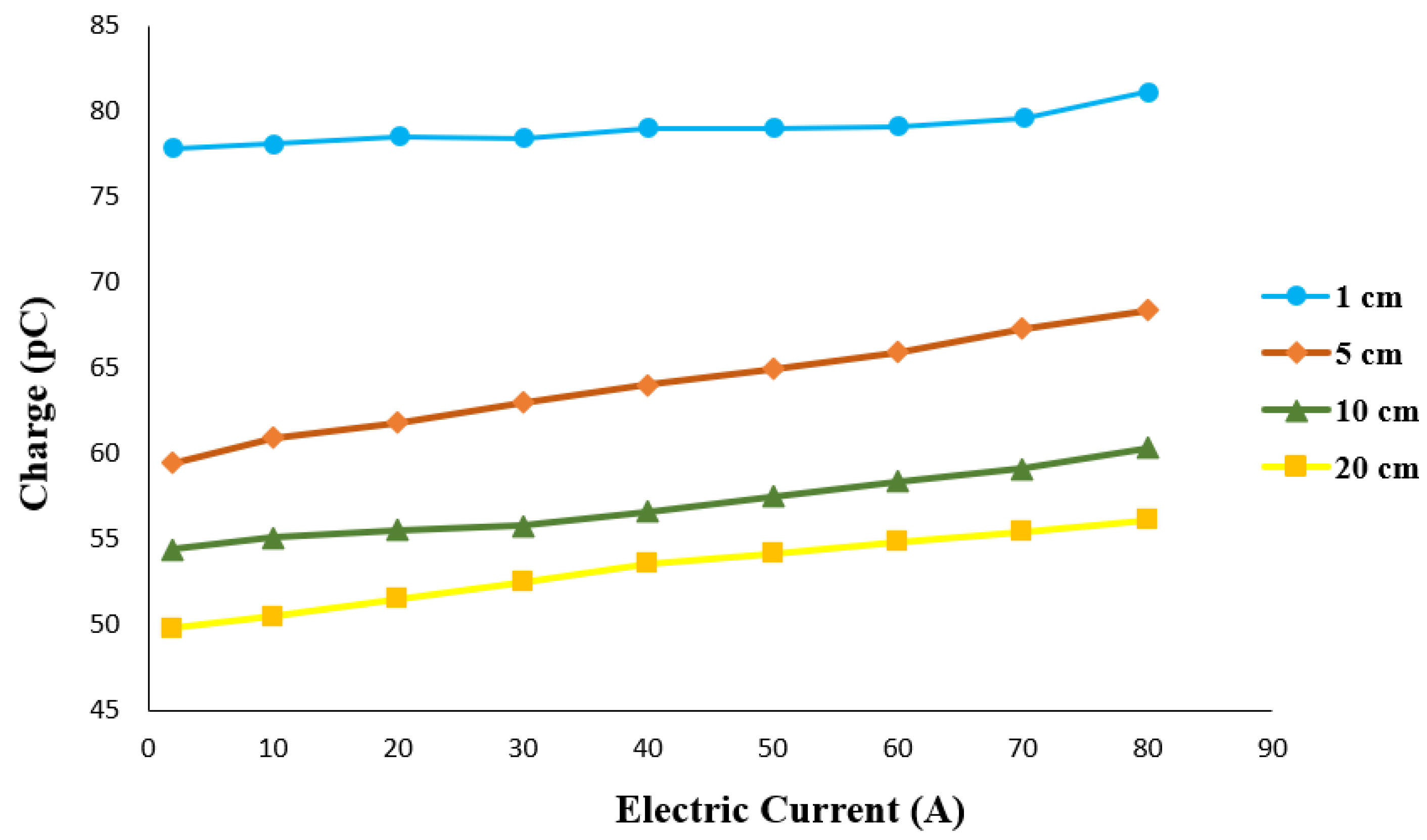
The graph depicted in Figure 4 relates the electrical response of the transducer due to the different levels of electrical current applied to the live wire, for the four distances considered in this study (distance between the transducer and the electrical wire).
One important feature that can be observed from this graph is that the response of the MPT, in terms of electrical charge output, to the electrical current field at different distances is notoriously distinct. This indicates that the magnetic field produced by the electrical current has an inverse relation to the distance between the sensor and the electrical wire, as expected.
In addition, the MPT clearly shows the increase of the amount of the electrical charge produced, with the increase of the electrical current, evidencing also a near linear relation between these two entities.
3.2. Piezoelectric and Piezo-Magnetic Coeficients
The piezoelectric coefficient () of the material represents the proportion between the dimensional variation of the piezoelectric material () and the potential difference applied, that is, between the generation of electrical charges and the mechanical stress () applied. The dimensional variation () is represented by:
where Y is Young’s modulus, is the variation of the applied mechanical stress and d is the total thickness.
The deformation caused in the polymer by the program of mechanical stress changes the balance of the electrical charges generated in the electrodes. The variation () of these electrical charges is given by eq. (4) [26].
where is the surface area of the electrodes, Q is the piezoelectric charge, is the density of positive charges on the electrode and is variation in the thickness of the air layer. Thus, the calculation of the piezoelectric coefficient , in the polymer, is given by eq. (5) [26].
where was considered equal to the electrical charge density , is the permittivity of piezoelectric polymers, is the density of positive charges trapped on the surface of piezoelectric polymers and F is the force.
In eq. (5), the material Young’s modulus is inversely proportional to the piezoelectric coefficient, that is, by increasing the elastic stiffness of the polymer, its piezoelectric coefficient decreases [3,27].
For the piezoelectric-magnetic coefficient (), the equation is like the one involving the piezoelectric coefficient. In this case, the applied loading is the mechanical stress caused by the magnetic field generated by the electrical field, eq. (6):
where is the magnetic field (Gauss).
In relation to the piezoelectric coefficient () and the piezo-magnetic coefficient (), in this experimental procedure, it is noted that high mechanical stress created by the magnetic field reduces this linear behavior in the MPTs. As described in [6], for low compression states, the piezoelectric and piezomagnetic coefficients increase.
This observation is also in good agreement with the data presented in Table 1 to Table 4. Obviously, this behavior was expected, since the piezoelectric activity of the samples remains the same, and only the amount of force applied via the magnetic field produced by electrical current changes in a direct and linear relation.

Table 1.
Piezoelectric and piezoelectric-magnetic coefficients obtained with the sensor 1 away from the electric current wire.
Table 1.
Piezoelectric and piezoelectric-magnetic coefficients obtained with the sensor 1 away from the electric current wire.
| Electrical Current | Piezoelectric Coefficient | Piezoelectric-magnetic Coefficient |
|---|---|---|
| [A] | [pC/N] | [pC/G] |
| 2 | 710,00 | 195,25 |
| 10 | 25,50 | 35,80 |
| 20 | 8,80 | 24,50 |
| 30 | 3,40 | 14,10 |
| 40 | 2,00 | 11,12 |
| 50 | 1,20 | 8,27 |
| 60 | 0,80 | 7,12 |
| 70 | 0,60 | 6,13 |
| 80 | 0,50 | 5,33 |
Table 2.
Piezoelectric and piezoelectric-magnetic coefficients obtained with the sensor 5 away from the electric current wire.
Table 2.
Piezoelectric and piezoelectric-magnetic coefficients obtained with the sensor 5 away from the electric current wire.
| Electrical Current | Piezoelectric Coefficient | Piezoelectric-magnetic Coefficient |
|---|---|---|
| [A] | [] | [] |
| 2 | 3494,12 | 990,00 |
| 10 | 105,00 | 145,00 |
| 20 | 34,53 | 98,10 |
| 30 | 13,76 | 57,71 |
| 40 | 7,13 | 43,24 |
| 50 | 5,09 | 35,66 |
| 60 | 3,09 | 25,94 |
| 70 | 2,53 | 24,83 |
| 80 | 1,94 | 21,68 |
Table 3.
Piezoelectric and piezoelectric-magnetic coefficients obtained with the sensor 10 away from the electric current wire.
Table 3.
Piezoelectric and piezoelectric-magnetic coefficients obtained with the sensor 10 away from the electric current wire.
| Electrical Current | Piezoelectric Coefficient | Piezoelectric-magnetic Coefficient |
|---|---|---|
| [A] | [] | [] |
| 2 | 5440,00 | 1360,00 |
| 10 | 229,58 | 324,12 |
| 20 | 60,33 | 168,18 |
| 30 | 27,09 | 113,88 |
| 40 | 13,67 | 76,49 |
| 50 | 8,05 | 56,37 |
| 60 | 6,00 | 50,26 |
| 70 | 4,79 | 46,90 |
| 80 | 3,72 | 42,17 |
Table 4.
Piezoelectric and piezoelectric-magnetic coefficients obtained with the sensor 20 away from the electric current wire.
Table 4.
Piezoelectric and piezoelectric-magnetic coefficients obtained with the sensor 20 away from the electric current wire.
| Electrical Current | Piezoelectric Coefficient | Piezoelectric-magnetic Coefficient |
|---|---|---|
| [A] | [] | [] |
| 2 | 8300,00 | 4980,00 |
| 10 | 459,09 | 631,25 |
| 20 | 114,44 | 321,88 |
| 30 | 43,03 | 181,03 |
| 40 | 26,49 | 148,61 |
| 50 | 18,40 | 128,81 |
| 60 | 11,46 | 96,14 |
| 70 | 7,75 | 75,89 |
| 80 | 6,35 | 71,01 |
It was observed that, when a high intensity electrical current was applied, the stress and resulting displacement fields in the piezoelectric cavities were outside the Hookean limits, the relation between the electrical current and the output signal ceased to be linear, and the piezoelectric-magnetic response becomes saturated.
The material behavior becomes thus non-linear and the transducer response loses the direct linear relation to the measured electrical field intensity.
It stands out from the optimization procedure, that the MPTs were able to exhibit a magnetoelectric effect when subjected to an external magnetic field, suffering an elastic deformation in the magnetic component and, consequently, promoting the macroscopic electrical polarization, due to the piezoelectric direct effect, which created a potential difference between the FEP layer and the magnetic layer.
Although there is still no research in the literature allowing the comparison of these results, it is inferred that the mechanical stress produced by magnetic fields produced by electrical currents, within the structure Hookean limits, present high piezoelectric and piezo-magnetic coefficients. In addition, it also proves the capacity of retention and storage of electrical charges of the here in proposed and developed MPTs. Finally, the results also demonstrate that MPTs are sensitive to electrical currents and can be used as valid and interesting non-invasive electrical current transducers.
4. Conclusions
This paper presented a proposal for the development and characterization of novel electrical current transducers, based on thermoformed magneto-piezoelectrets.
The developed electrical current transducer was able to detect the electromagnetic field created by an electrical current traveling along an electrical conductor (electrical wire). This magnetic effect was able to produce an electrical charge in the piezoelectric layer, assessing thus the transducer response. Therefore, the additional magnetostrictive material layer not only optimized the piezoelectric effect of the MPTs, but also allowed them to respond to external magnetic fields with optimal piezoelectric and piezo-magnetic coefficients.
The results gathered through experimental tests, aiming at the characterization of the transducer sensitivity to electrical currents, demonstrated that the electrical charge in this configuration has a linear relation to the observed electrical current. In relation to the piezoelectric coefficient and the piezo-magnetic coefficient, it was observed that the voltage in the MPTs, caused by the presence of a magnetic field produced by electrical currents, when high, tends to cancel this linear relation.
Finally, the obtained results confirm the investigation relevance to understand the optimization of the transducers, and their physical principle of operation.
Author Contributions
Experimental investigation, methodology, conceptualization of study, writing, A. S., R. P. and R. M.; funding acquisition, supervision of investigation, R. C., R. P. and R. M. All authors have read and agreed to the published version of the manuscript.
Funding
This research was funded by CAPES grant number: 88882.328947/2019-01.
Institutional Review Board Statement
Not applicable
Informed Consent Statement
Not applicable.
Conflicts of Interest
The authors declare no conflict of interest. The funders had no role in the design of the study; in the collection, analyses, or interpretation of data; in the writing of the manuscript; or in the decision to publish the results.
References
- Nguyen, D.N.; Moon, W. Piezoelectric polymer microfiber-based composite for the flexible ultra-sensitive pressure sensor. Journal of Applied Polymer Science 2019. [CrossRef]
- Ünsal, F.; Altın, Y.; Çelik Bedeloğlu, A. Poly(vinylidene fluoride) nanofiber-based piezoelectric nanogenerators using reduced graphene oxide/polyaniline. Journal of Applied Polymer Science 2020. [CrossRef]
- Tichý, J.; Erhart, J.; Kittinger, E.; Přívratská, J. Fundamentals of piezoelectric sensorics: Mechanical, dielectric, and thermodynamical properties of piezoelectric materials; 2010. [CrossRef]
- Altafim, R.A.C.; Basso, H.C.; Neto, L.G.; Lima, L.; Altafim, R.A.P.; De Aquino, C.V. Piezoelectricity in multi-air voids electrets. In Proceedings of the Annual Report - Conference on Electrical Insulation and Dielectric Phenomena, CEIDP, 2005, Vol. 2005, pp. 669–672. [CrossRef]
- De Carvalho, F.J.; Altafim, R.A.C.; Assagra, Y.A.O.; Borges, B.H.V.; Altafim, R.A.P. Electric circuit model for simulating ferroelectrets with open-tubular channels. In Proceedings of the Annual Report - Conference on Electrical Insulation and Dielectric Phenomena, CEIDP. Institute of Electrical and Electronics Engineers Inc., 2016, Vol. 2016-December, pp. 315–318. [CrossRef]
- Zhukov, S.; Eder-Goy, D.; Fedosov, S.; Xu, B.X.; Von Seggern, H. Analytical prediction of the piezoelectric d 33 response of fluoropolymer arrays with tubular air channels. Scientific Reports 2018, 8. [CrossRef]
- Altafim, R.A.P. Novos piezoeletretos: desenvolvimento e caracterização. PhD thesis, Escola de Engenharia de São Carlos, Universidade de São Paulo, São Carlos, 2010. [CrossRef]
- Altafim, R.A.P.; Basso, H.C.; Altafim, R.A.C.; Qiu, X.; Wirges, W.; Gerhard, R. A comparison of polymer piezoelectrets with open and closed tubular channels: Pressure dependence, resonance frequency, and behavior under humidity. In Proceedings of the Proceedings - International Symposium on Electrets, 2011, pp. 213–214. [CrossRef]
- Falconi, D.R.; Altafim, R.A.; Altafim, R.A.; Basso, H.C. Multi-layers fluoroethylenepropylene (FEP) films bounded with adhesive tape to create piezoelectrets with controlled cavities. In Proceedings of the Annual Report - Conference on Electrical Insulation and Dielectric Phenomena, CEIDP, 2011, pp. 137–140. [CrossRef]
- Sun, Z.; Zhang, X.; Xia, Z.; Qiu, X.; Wirges, W.; Gerhard, R.; Zeng, C.; Zhang, C.; Wang, B. Investigation into polarization and piezoelectricity in polymer films with artificial void structure. In Proceedings of the Proceedings - International Symposium on Electrets, 2011, pp. 23–24. [CrossRef]
- Rychkov, D.; Altafim, R.A.P. Template-based fluoroethylenepropylene ferroelectrets with enhanced thermal stability of piezoelectricity. Journal of Applied Physics 2018, 124. [CrossRef]
- Mellinger, A.; Wegener, M.; Wirges, W.; Gerhard-Multhaupt, R. Thermally stable dynamic piezoelectricity in sandwich films of porous and nonporous amorphous fluoropolymer. Applied Physics Letters 2001, 79, 1852–1854. [CrossRef]
- Pukada, E. History and recent progress in piezoelectric polymers. IEEE Transactions on Ultrasonics, Ferroelectrics, and Frequency Control 2000, 47, 1277–1290. [CrossRef]
- Wegener, M.; Wirges, W.; Künstler, W.; Gerhard-Multhaupt, R.; Elling, B.; Pinnow, M.; Danz, R. Coating of porous polytetrafluoroethylene films with other polymers for electret applications. Conference on Electrical Insulation and Dielectric Phenomena (CEIDP), Annual Report 2001. [CrossRef]
- Altafim, R.A.C.; Basso, H.C.; Altafim, R.A.P.; Lima, L.; de Aquino, C.V.; Neto, L.G.; Gerhard-Multhaupt, R. Piezoelectrets from thermo-formed bubble structures of fluoropolymer-electret films. IEEE Transactions on Dielectrics and Electrical Insulation 2006, 13, 979–985. [CrossRef]
- Fang, P.; Wirges, W.; Gerhard, R.; Zirkel, L. Charging conditions for cellular-polymer ferroelectrets with enhanced thermal stability. In Proceedings of the Proceedings - International Symposium on Electrets, 2008. [CrossRef]
- Altafim, R.A.P.; Altafim, R.A.C.; Qiu, X.; Raabe, S.; Wirges, W.; Basso, H.C.; Gerhard, R. Fluoropolymer piezoelectrets with tubular channels: Resonance behavior controlled by channel geometry. Applied Physics A: Materials Science and Processing 2012, 107, 965–970. [CrossRef]
- Altafim, R.A.P.; Altafim, R.A.C.; Basso, H.C.; Qiu, X.; Wirges, W.; Gerhard, R. Fluoroethylenepropylene ferroelectrets with superimposed multi-layer tubular void channels. In Proceedings of the Annual Report - Conference on Electrical Insulation and Dielectric Phenomena, CEIDP, 2011, pp. 133–136. [CrossRef]
- Jang, S.M.; Bichurin, M.I.; Yang, S.C. Hydrothermal synthesis of Bi-magnetic clusters for magnetoelectric composites. Materials Research Bulletin 2017, 91, 197–202. [CrossRef]
- Nan, C.W. Magnetoelectric effect in composites of piezoelectric and piezomagnetic phases. Physical Review B 1994. [CrossRef]
- Tan, K.; Wen, X.; Deng, Q.; Shen, S.; Liu, L.; Sharma, P. Soft rubber as a magnetoelectric material—Generating electricity from the remote action of a magnetic field. Materials Today 2021, 43. [CrossRef]
- Ma, J.; Hu, J.; Li, Z.; Nan, C.W. Recent progress in multiferroic magnetoelectric composites: From bulk to thin films. Advanced Materials 2011, 23, 1062–1087. [CrossRef]
- Qureshi, M.S.; Bhatnagar, C.S. Calculation of an equivalent electric field from thermally stimulated discharge current of perspex magneto-electrets. Indian Journal of Pure and Applied Physics 1979, 17, 575–582.
- Altafim, R.A.P.; Assagra, Y.A.O.; Altafim, R.A.C.; Carmo, J.P.; Palitó, T.T.C.; Santos, A.M.; Rychkov, D. Piezoelectric-magnetic behavior of ferroelectrets coated with magnetic layer. Applied Physics Letters 2021, 119. [CrossRef]
- Altafim, R.A.P.; Altafim, R.A.C. History and recent progress in ferroelectrets produced in Brazil. Journal of Advanced Dielectrics 2023, p. 2341007. [CrossRef]
- Yang, J. An Introduction to the Theory of Piezoelectricity; Kluwer Academic Publishers, 2005. [CrossRef]
- Li, F.; Lin, D.; Chen, Z.; Cheng, Z.; Wang, J.; Li, C.; Xu, Z.; Huang, Q.; Liao, X.; Chen, L.Q.; et al. Ultrahigh piezoelectricity in ferroelectric ceramics by design. Nature Materials 2018. [CrossRef]
Figure 1.
(a) Fabrication procedure for Magneto-Piezoelectret Thermoformed (MPT) with open tubular channels and piezoelectric-magnetic response. (b) Magneto-Piezoelectret Thermoformed.
Figure 1.
(a) Fabrication procedure for Magneto-Piezoelectret Thermoformed (MPT) with open tubular channels and piezoelectric-magnetic response. (b) Magneto-Piezoelectret Thermoformed.
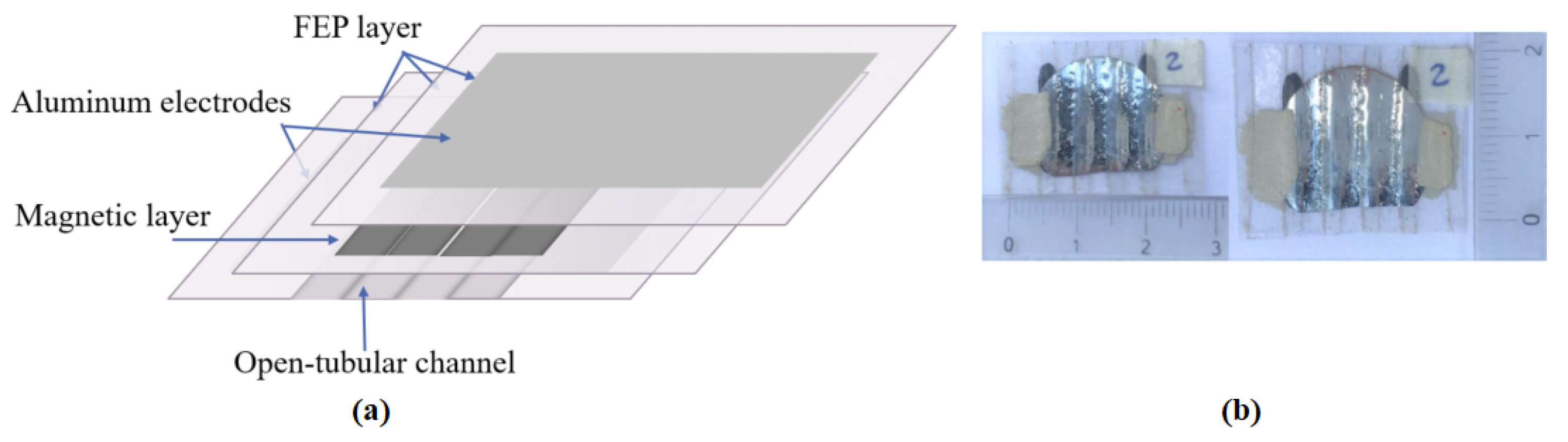
Figure 2.
(a) Schematic representation of the current sensor with metallic housing. (b) Image of the front of the metal casing. (c) Image of the back of the metal enclosure.
Figure 2.
(a) Schematic representation of the current sensor with metallic housing. (b) Image of the front of the metal casing. (c) Image of the back of the metal enclosure.
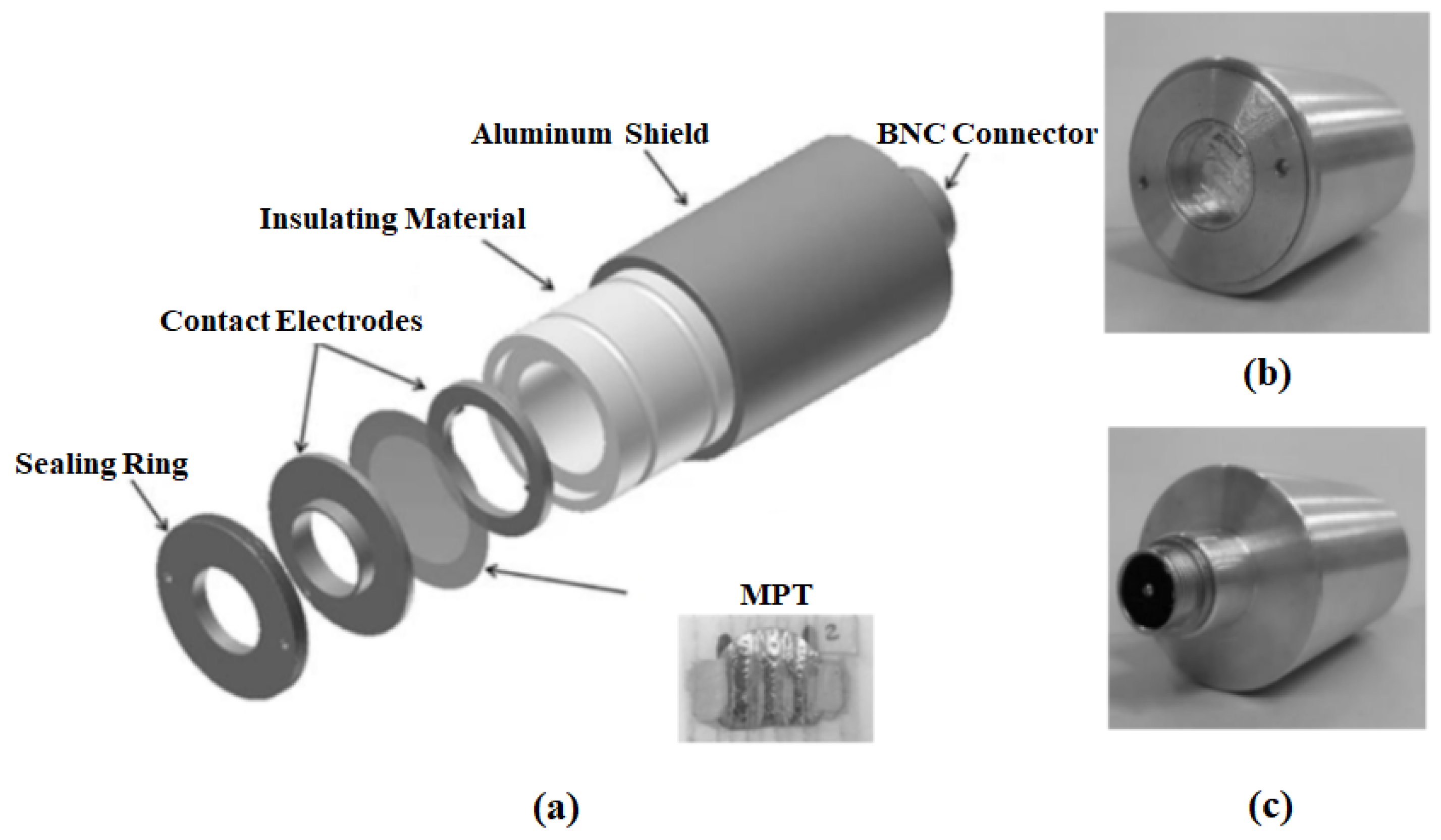
Figure 3.
(a) Metal housing with the MPT. (b) Schematic drawing of current flow and magnetic field orientation. (c) Current Transformer.
Figure 3.
(a) Metal housing with the MPT. (b) Schematic drawing of current flow and magnetic field orientation. (c) Current Transformer.
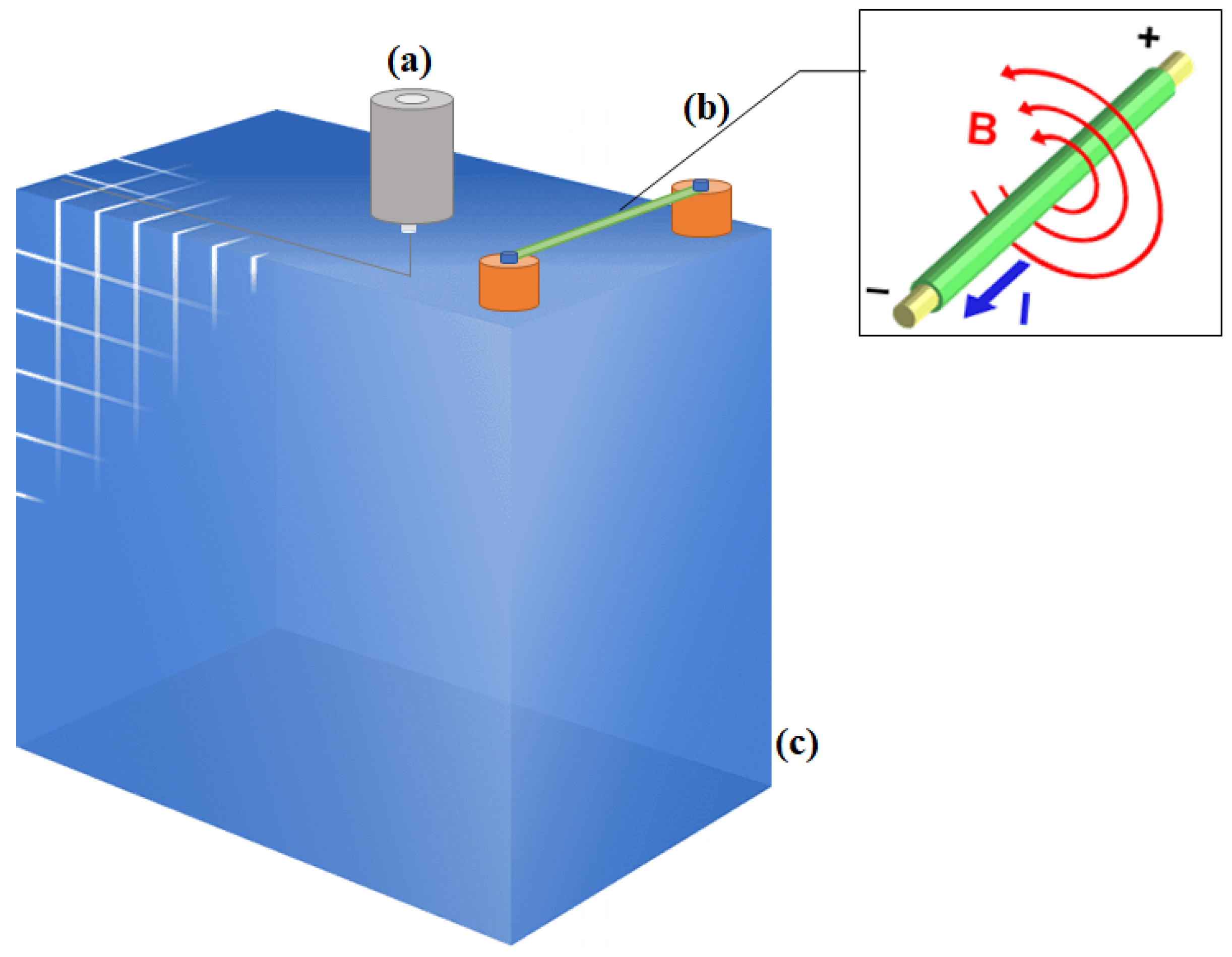
Figure 4.
Piezoelectric charges generated at different electric currents and distances.
Disclaimer/Publisher’s Note: The statements, opinions and data contained in all publications are solely those of the individual author(s) and contributor(s) and not of MDPI and/or the editor(s). MDPI and/or the editor(s) disclaim responsibility for any injury to people or property resulting from any ideas, methods, instructions or products referred to in the content. |
© 2023 by the authors. Licensee MDPI, Basel, Switzerland. This article is an open access article distributed under the terms and conditions of the Creative Commons Attribution (CC BY) license (http://creativecommons.org/licenses/by/4.0/).
Copyright: This open access article is published under a Creative Commons CC BY 4.0 license, which permit the free download, distribution, and reuse, provided that the author and preprint are cited in any reuse.


