
Submitted:
02 August 2023
Posted:
03 August 2023
You are already at the latest version
Abstract
In this work, a systematic study was conducted on the fabrication of multi-material components obtained employing Laser-Powder Bed Fusion (L-PBF) technology. The idea of making multi-material components is a winning capability of additive technologies because it allows the fabrication of Functionally Graded Materials (FGMs) with the customization of parts according to different required properties. The transition from one material to another was achieved gradually and continuously within the same layer using ad-hoc equipment designed for L-PBF systems with a powder spreading technique based on coaters or rollers. The influence of the relative position of the different materials within the powder chamber and the geometry of the developed equipment on the metallurgical and mechanical properties of the manufactured samples was evaluated. The performed tests involved the use of two materials, a nickel-based superalloy, and a stainless steel, having different chemical, physical and mechanical properties to obtain gradual properties variation in the manufactured samples. Based on the results of post-process characterization obtained through metallographic, chemical, and mechanical analysis, the relative positions of the materials and the geometry of the developed equipment have a limited effect on the sample’s manufactured properties. The characteristics of the FGM zone depend on the nature of the employed powders, and its extent coincides with that defined during the design of the divider.
Keywords:
additive manufacturing
; laser-powder bed fusion
; functionally graded materials
; multi-material layer-level
; nickel superalloy
; stainless steel.
1. Introduction
There is a growing need in the manufacturing sector to develop methods and processes to produce components that meet increasingly specific requirements. From this perspective, additive manufacturing is an innovative and versatile tool to meet these challenges by enabling the fabrication of components with complex geometries in a relatively cost-effective manner[1,2,3]. Laser-Powder Bed Fusion (L-PBF) is an additive manufacturing process that is advancing in the production of multi-material metallic structures with complex geometries[4]. However, the fabrication of multi-material parts using L-PBF is a challenging task because it requires the deposition of two or more powders in a layer-by-layer fashion[5,6,7]. This can be achieved by using machines specifically designed to process powders of different materials while processing the same layer[8]. However, this solution requires a prohibitive capital investment. An alternative is to manufacture auxiliary equipment for existing L-PBF machines that would allow the different types of powders to be appropriately separated during the machine set-up. Hence, the powder distribution system then determines the mixing of the materials through the movement of a coater or roller [9]. Therefore, by appropriately utilizing the capabilities of L-PBF machines, it is possible to achieve smooth transitions between different materials (between the layers and at layer-level). This result falls within the realm of Functionally Graded Materials (FGMs), which increase the ability to tailor the final properties of components to their function. For example, parts can be obtained with a lighter core, while the exterior can be made of a different material compatible with the environment in which the part will be used, avoiding abrupt changes in chemical composition and mechanical properties [10,11,12].
However, research of extreme interest related to FGM fabrication is the study and characterization of powders used in the process. The characterization of metal powders used in L-PBF processes is a topic that many researchers have investigated to determine the correlations between the measurable and observable properties of the particles prior to melting and the quality of the manufactured components. Hilzenthaler et al. investigated the characterization of virgin and recycled steel powders by morphological, chemical, mechanical, and electrical analyses[13]. Among other results, they confirmed that a larger powder particle size results in higher flowability, as also verified in previous work[13,14]. The mechanical properties of the components were also related to the powder particle size in the case of 17-4 PH steel. The results show that the best properties are obtained when the particle diameter is in the range of 20÷40 μm [12].
Several studies, performed with more complex spreading systems not based on a coater or roller, have verified the feasibility of powder bed laser processing on different materials mixed in the same layer and have investigated the metallurgical properties of the resulting parts[15,16,17]. It is likely that the different physical, chemical, and geometric properties of different powders affect the way they interact during the spreading phase from the powder chamber to the building platform. Regarding systems using the coater or roller for powder bed spreading, some studies have attempted to use numerical simulations to infer the influence of powder particle size and flowability on the built samples [18,19]. Hence, this is the first systematic experimental work on the influence of the mutual position of the different materials during the distribution of the powder bed by the coater or the roller. An attempt was made to evaluate whether the initial position of the powders affects the formation of the powder bed and, ultimately, the properties of the manufactured component. In addition, the effect of the geometry of the auxiliary equipment, designed to allow the appropriate separation of different types of powders during machine set-up, on the mechanical and metallurgical properties of the samples produced was evaluated. In order to obtain the desired properties of the samples, tests were conducted using two materials - a nickel-based superalloy and a stainless steel - each with different chemical, physical, and mechanical properties. According to the results of post-process characterization obtained through metallographic, chemical, and mechanical analyses, the relative positions of the materials and the geometry of the developed equipment have a limited effect on the sample’s manufactured properties.
2. Materials and Methods
2.1. Materials and Equipment
This experimental work was performed using an L-PBF processing machine by Concept Laser (M1 Cusing). The machine is equipped with a Nd:YAG laser source with a wavelength of 1064 nm. The machine uses a rubber coater as a powder spreading system that moved from the powder chamber to the building platform. The first material selected for experimentation was AISI 316L austenitic steel. The other alloy was a nickel-based superalloy. Both powders were obtained by a gas atomization manufacturing process and were sieved to select particle sizes between 15 and 45 µm. The chemical composition of the two powders was determined by EDX microanalysis using a scanning electron microscope, the results of which are shown in Table 1. The SEM analysis also showed that the powder particles of both materials had a well-defined spherical shape, with few anomalies such as satellites or elongated particles that could affect the proper formation of the powder bed (Figure 1). To properly separate the two materials during machine set-up and subsequently achieve their mixing in a well-defined horizontal band on the building platform, specific auxiliary equipment was designed and constructed. This equipment consists mainly of two vertical thin walls inclined at an appropriate angle α to the coater's direction of movement (Figure 2). The angle was chosen to obtain a mixing zone between the two materials with a width of 20 mm. In this zone, the composition of the mixture changed gradually from the first material to the second, according to a theoretically linear law. In this way, a component called Continuous Functionally Graded Material (CFGM) was obtained.
2.2. Experimental plan and process parameters
To maximize the results of each test, two dividers were used, each having two parallel walls. Thus, two different combinations were tested in the same production batch. In fact, in Figure 2a, it can be seen that the walls of the divider were inclined by the angle α1 with respect to the direction of movement of the coater. This inclination determined the mixing mode between the powder outside the two walls, AISI 316L (henceforth referred to as A), and the powder between them, Nickel Superalloy (henceforth referred to as B). The angle α1 causes material B to be dragged over material A in the band defined by the top wall of the partition. The mixing mode of the materials is reversed in the zone of influence of the lower wall of the same divider, so that here material A is dragged onto material B. Figure 2b shows that the walls of the second divider are tilted in the opposite direction to the previous case, resulting in an opposite effect during the distribution and mixing of the materials. The experiment then involved the fabrication of four types of specimens, identified by the angle of wall tilt and the order in which the materials were mixed. The specimens had a total length in the plane (XY) of 30 mm, with a 5 mm zone consisting of AISI316L at one end and a 5 mm zone consisting of the nickel superalloy at the other end. The total height of the specimens along the Z-axis is 10 mm. Between these two zones, there was a transition area 20 mm long, where materials A (AISI316L) and B (nickel superalloy) gradually mix. A schematic of the composition of the sample is shown in Figure 3.
For each type of specimen, a replication was made in each print to allow for further investigation. Finally, Figure 4 shows a sketch of the specimens made with the identification used (the symbol " ' " indicates that it is the replication of the specimen with the same name).
Process parameter values optimized through previous work were used to create all samples [9]. Furthermore, the same set of process parameters were used across the whole laser-scanned surface despite the presence of two different materials. The following parameters were used: 100 W laser power, 200 mm/s scanning speed, 200 μm laser spot size, 140 μm hatch spacing, and 30 μm layer thickness. To minimize the thermal stresses generated during printing, samples were made by the random square island scanning technique, each square with a side of 5 mm.
2.3. Metallographic and hardness test
To assess the quality of the fabricated samples qualitatively and quantitatively, and to evaluate the influence of the different combinations studied (mentioned in Section 2.2) on the final properties of the produced components, extensive metallurgical (defect, microstructural, and chemical analysis) and mechanical (microhardness tests) characterization was carried out on all the fabricated samples. The metallographic examination was performed by cutting the specimens through a metallographic cut-off machine, hot mounting of sections in resin, and polishing them with abrasive papers and diamond pastes. Subsequently, the specimens were observed in the as-polished state to easily quantify the porosity and observe the possible presence of other defects such as cracks and lack of fusion. A Nikon Eclipse MA200 inverted optical microscope was used for this purpose.
The test specimens were subjected to chemical etching to highlight the microstructure and more clearly observe the result of cFGM-oriented fabrication. Glyceregia was used as the chemical reagent. This etching solution consisted of lactic acid, hydrochloric acid, and nitric acid in a ratio of 6:2:1. The analysis of the acquired images was performed using the open-source software ImageJ, which allowed the extraction of quantitative information that was subsequently processed using Matlab.
To determine the trends in the composition of the samples, a chemical elemental analysis was performed using a GeminiSEM 500 scanning electron microscope (SEM) equipped with an OXFORD EDS Oxford Aztec Live with Ultim Max 100 detector.
The Vickers HV1 mechanical hardness test was performed, using Shimadzu HMV-G microhardness tester, on the same sections used for the metallographic examination.
3. Results and Discussion
3.1. Metallographic examination
Metallographic analyses to determine the metallurgical quality and microstructure of the samples were carried out by sectioning in both XY and YZ planes. Considering Figure 4, the identification of the metallographic specimens is shown in Table 2. After polishing the mounted section surfaces, they were observed with an optical microscope and photographed, revealing the appearance of a central band on the specimens that extends along Y direction (Figure 5). Figure 5 shows that, in all four cases and in the respective replications, the transition zone between the two materials was free of defects such as lack of fusion and delamination, which demonstrated the goodness of the equipment implemented in this study for cFGM fabrication[9].
However, micrographs without chemical etching showed that the two materials behaved differently towards the L-PBF process. The nickel superalloy, which is always on the left in the various images, was affected by numerous cracks, that usually plague materials that are not very resistant to rapid melting and resolidification cycles[20]. The austenitic steel, on the other hand, was crack-free and showed only a small percentage of porosity, which is considered physiological in the L-PBF process.
Figure 6 shows the distribution of the number of discontinuities along the XY and YZ planes. The examined sections were divided into bands of 2 mm width and in each band, the detected discontinuities were counted without taking into account their size. This distribution seemed to follow the same trend as the percentage of nickel superalloy powder, with a maximum value at the left end and tending to decrease moving toward AISI 316L (see Figure 6a). However, this behavior was not perfectly the same as the angle of the wall changes. In fact, in the metallographic specimens 3 and 4 (see Figure 6c) this tendency is less pronounced, and the total number of discontinuities is also reduced compared with that in specimens 1 and 2 (see Figure 6b).
After etching, each area of the specimen composed of one of the two materials showed the typical microstructures of that alloy. In fact, Figure 7a shows an austenitic structure. Furthermore, in the section parallel to the XY plane, the edges of the 45° laser passes are visible, in accordance with the square island strategy used for manufacturing. Figure 7c, on the other hand, shows the microstructure of the nickel superalloy observed in the cross section, characterized by a dendritic morphology[21]. Figure 7b shows the appearance of the microstructure within the mixed zone, where the characteristics of both materials were found [22].
3.2. Hardness Test
The Vickers HV1 hardness test was carried out according to the international standard ISO 6507-1 using a load application time of 15 seconds on the surface to be tested. Each specimen listed in Table 2 was tested in six different equispaced zones along the main direction of the specimen, as shown in Figure 8. Three tests were performed at each measurement position and their mean and standard deviation were calculated to statistically compare the results and verify the influence of different factors on the hardness (see Figure 9 and Figure 10). In particular, an attempt was made to determine how the angle of the divider’s wall and the reciprocal position of the powders could affect the mechanical properties of the specimens. However, the comparison between XY plane and YZ plane sections was not carried out because the L-PBF manufacturing process results in an anisotropic structure in the manufactured components and therefore it is obvious to detect differences even in the hardness values measured on perpendicular surfaces. The results showed that although in all cases there was a gradual reduction in hardness moving towards AISI 316L, going from ≈370HV to ≈220HV, both the angle of the divider and the relative position between the powders had an influence on the evolution of the values.
Figure 9 shows summary graphs of the observed hardness trends in the different cases analyzed, comparing the hardness values of the fabricated specimens with the different divider angles. Comparing the graphs, it can be seen that the hardness of the AB-type specimens produced with the angle α1 tended to remain higher than that of the AB-type specimens produced with the angle α2 divider up to half the tested length (see Figure 9a and Figure 9c). Since the higher hardness is due to the greater presence of nickel superalloy, it can be concluded that it was transported to a much greater extent along the Y-direction when the α1 angle divider was used than in the other case (as for the AB-type samples). This difference is not observed in the case of the BA-type specimens produced with both angles, because the values of hardness found were comparable in the different cases (see Figure 9b and Figure 9d).
Figure 10 shows summary graphs of the observed hardness trends in the different cases analyzed, comparing the hardness values of the fabricated specimens with different mutual positions of the materials during the distribution of the powder bed. Comparing the graphs, it is possible to show that in the case of the α2 divider (see Figure 10a and Figure 10c), the BA-type specimens showed a greater extent of the area affected by the nickel superalloy and this result was due to higher hardness values for almost half of the specimen (a result that was more evident in the case of the XY plane sections); while in the case of the α1 divider (see Figure 10b and Figure 10d), the same kind of phenomenon is observed in the AB type specimens (especially in the specimens obtained from the sections along the YZ plane). The results indicate that the factors considered in the experiment have limited influence on the hardness of different samples produced.
3.3. Chemical analysis
Chemical analysis by scanning electron microscope was carried out on the YZ plane of all samples at 2.5 mm intervals. The weight concentration of the chemical elements differentiating the two materials was measured to see if the theoretical linear variation imposed by the shape of the divider was confirmed by instrumental analysis. Elements present in one material and absent in the other were examined. Specifically, the elements Mn, Fe (present in AISI 316L and absent in the nickel superalloy) and Co, Al, Ti (present in the nickel superalloy and absent in AISI 316L) were analyzed. To better highlight trends in chemical concentrations, the values related to the maximum measured value for each chemical element were plotted. As can be seen from the graphs in Figure 11, in all four cases studied, all the measured chemical elements showed a weight percentage that follows the expected trend. The first three measurement points, which belonged to the area where only AISI 316L steel was present, showed a flat trend precisely because this was a part of the sample not affected by the cFGM. The same result was found for the last three points, which belonged to the area where only nickel superalloy was present.
These results were identical for all the tested samples. Hence, the designed equipment allowed to obtain components with gradual chemical compositions changing within a predetermined range and in a well-defined bandwidth, avoiding any type of contamination in the other areas. This is an excellent result compared to the results already published in the scientific literature. In fact, as mentioned in the review by Wang et al. [4], L-PBF machines already on the market with a bottom-down powder chamber and a coater-based powder spreading system are severely limited for multi-material fabrication within the same layer due to strong contamination problems.
From the results shown in Figure 11, it can also be noted that the BA-type specimens, in both the α1 and α2 cases, showed a less gradual trend; in fact, as can be seen in both Figure 11b and Figure 11c, which referred to the 2T and 3T specimens respectively, there was a sudden change in the chemical concentration of the elements in the 20 mm - 25 mm range (along Y-direction). On the other hand, for the AB-type samples, in both cases of α, the change in chemical concentration of the representative elements was more gradual throughout the sample. This result showed that the relative position between materials is influential in cFGM fabrication at the layer level and is a parameter that can be considered, while the different angle of the divider is negligible, at least from the point of view of chemical analysis.
The results of the chemical analysis were consistent with the results of the hardness tests. It can be seen that in the case of the BA-type specimens, a portion of the specimens about 20 mm long had a hardness value very close to that of AISI 316L (see Figure 9b), and this result was consistent with what is seen in Figure 11b and Figure 11c, where about 20 mm of the specimen had a chemical composition very close to that of AISI 316L. While the AB-type specimens showed a gradual change both in mechanical properties, as determined by hardness tests (see Figure 9a), and chemical properties (see Figure 11a and Figure 11d).
4. Conclusions
This experimental work presents a systematic study of the fabrication of multi-material parts at the layer level using the Laser-Powder Bed Fusion process. Specifically, the study aimed to determine the ability of an inexpensive system, adaptable to the L-PBF machines already on the market, to produce parts with continuously variable properties in each layer. The focus was on the correlation between some freely selectable factors in the production design and the result obtained in terms of metallurgical and mechanical properties, and chemical composition. The factors studied were the relative position of the different materials within the powder chamber and the geometry of the equipment designed to produce the cFGMs components. The analyses performed and the main results obtained are summarized below.
- Metallographic examinations have demonstrated the feasibility of producing cFGMs components at the layer level with the system presented in this work; in fact, the interface of the produced samples appeared to be free of defects such as lack of fusion and delamination, synonymous with the good metallurgical bond created between the materials investigated in this work.
- The hardness tests confirmed the presence of a graded zone equal to that set by the divider (20 mm, along the Y direction), within which there was a continuous and gradual change in mechanical properties. In addition, the hardness test results showed a limited influence of both analyzed factors on the final mechanical properties of the produced samples.
- The chemical analyses revealed the variation of chemical properties along the grading direction in all the produced samples; however, from the same analyses, the factor of relative position between different powders was found to have a certain influence on the final result.
According to the results of post-process characterization obtained through metallographic, chemical, and mechanical analyses, it can be stated that the used divider could be designed in different configurations without significantly affecting the properties of the samples produced. The characteristics of the FGM zone depend on the nature of the employed powders, and its extent coincides with that defined during the design of the divider.
Further development of this work could include the study of the tribological characteristics of the powders used and how the contact between chemically and geometrically different particles affects the powder bed coating, also using numerical simulations.
Author Contributions
Conceptualization, V.E. and P.P.; methodology, V.E. and P.P.; software, V.E. and P.P; validation, V.E., A.A. and S.C.; formal analysis, V.E. and P.P.; investigation, V.E. and P.P.; resources, A.A. and S.C.; data curation, V.E. and P.P; writing—original draft preparation, V.E. and P.P.; writing—review and editing, V.E., A.A. and S.C.; visualization, V.E., P.P., A.A. and S.C.; supervision, A.A. and S.C.; project administration, S.C.; funding acquisition, S.C. All authors have read and agreed to the published version of the manuscript.
Conflicts of Interest
The authors declare no conflict of interest.
References
- Liu, L.; Wang, D.; Deng, G.; Yang, Y.; Chen, J.; Tang, J.; Wang, Y.; Liu, Y.; Yang, X.; Zhang, Y. Interfacial Characteristics and Formation Mechanisms of Copper–Steel Multimaterial Structures Fabricated via Laser Powder Bed Fusion Using Different Building Strategies. Chinese Journal of Mechanical Engineering: Additive Manufacturing Frontiers 2022, 1, 100045. [Google Scholar] [CrossRef]
- Grazia Guerra, M.; Lafirenza, M.; Errico, V.; Angelastro, A. In-Process Dimensional and Geometrical Characterization of Laser-Powder Bed Fusion Lattice Structures through High-Resolution Optical Tomography. Opt Laser Technol 2023, 162, 109252. [Google Scholar] [CrossRef]
- Schanz, J.; Islam, N.; Kolb, D.; Harrison, D.K.; Silva, A.K.M. De; Goll, D.; Schneider, G.; Riegel, H. Individual Process Development of Single and Multi-Material Laser Melting in Novel Modular Laser Powder Bed Fusion System. Progress in additive manufacturing 2022. [Google Scholar] [CrossRef]
- Wang, D.; Liu, L.; Deng, G.; Deng, C.; Bai, Y.; Yang, Y.; Wu, W.; Chen, J.; Liu, Y.; Wang, Y.; et al. Recent Progress on Additive Manufacturing of Multi-Material Structures with Laser Powder Bed Fusion. Virtual Phys Prototyp 2022, 17, 329–365. [Google Scholar] [CrossRef]
- Wei, C.; Li, L. Recent Progress and Scientific Challenges in Multi-Material Additive Manufacturing via Laser-Based Powder Bed Fusion. Virtual Phys Prototyp 2021, 16, 347–371. [Google Scholar] [CrossRef]
- Gu, H.; Wei, C.; Li, L.; Han, Q.; Setchi, R.; Ryan, M.; Li, Q. Multi-Physics Modelling of Molten Pool Development and Track Formation in Multi-Track, Multi-Layer and Multi-Material Selective Laser Melting. Int J Heat Mass Transf 2020, 151, 119458. [Google Scholar] [CrossRef]
- Mussatto, A. Research Progress in Multi-Material Laser-Powder Bed Fusion Additive Manufacturing: A Review of the State-of-the-Art Techniques for Depositing Multiple Powders with Spatial Selectivity in a Single Layer. Results in Engineering 2022, 16, 100769. [Google Scholar] [CrossRef]
- Wei, C.; Li, L.; Zhang, X.; Chueh, Y.-H. 3D Printing of Multiple Metallic Materials via Modified Selective Laser Melting. CIRP Annals 2018, 67, 245–248. [Google Scholar] [CrossRef]
- Errico, V.; Posa, P.; Fusco, A.; Angelastro, A.; Campanelli, S.L. Intralayer Multi-Material Structure Stainless-Steel/Nickel-Superalloy Fabricated via Laser-Powder Bed Fusion Process. Manuf Lett 2023, 35, 11–15. [Google Scholar] [CrossRef]
- Dubey, A.; Jaiswal, S.; Lahiri, D. Promises of Functionally Graded Material in Bone Regeneration: Current Trends, Properties, and Challenges. ACS Biomater Sci Eng 2022, 8, 1001–1027. [Google Scholar] [CrossRef]
- Rouf, S.; Malik, A.; Raina, A.; Irfan Ul Haq, M.; Naveed, N.; Zolfagharian, A.; Bodaghi, M. Functionally Graded Additive Manufacturing for Orthopedic Applications. J Orthop 2022, 33, 70–80. [Google Scholar] [CrossRef]
- Sefene, E.M. State-of-the-Art of Selective Laser Melting Process: A Comprehensive Review. J Manuf Syst 2022, 63, 250–274. [Google Scholar] [CrossRef]
- Hilzenthaler, M.; Bifano, L.; Scherm, F.; Fischerauer, G.; Seemann, A.; Glatzel, U. Characterization of Recycled AISI 904L Superaustenitic Steel Powder and Influence on Selective Laser Melted Parts. Powder Technol 2021, 391, 57–68. [Google Scholar] [CrossRef]
- Sutton, A.T.; Kriewall, C.S.; Karnati, S.; Leu, M.C.; Newkirk, J.W. Characterization of AISI 304L Stainless Steel Powder Recycled in the Laser Powder-Bed Fusion Process. Addit Manuf 2020, 32, 100981. [Google Scholar] [CrossRef]
- Liu, Z.H.; Zhang, D.Q.; Sing, S.L.; Chua, C.K.; Loh, L.E. Interfacial Characterization of SLM Parts in Multi-Material Processing: Metallurgical Diffusion between 316L Stainless Steel and C18400 Copper Alloy. Mater Charact 2014, 94, 116–125. [Google Scholar] [CrossRef]
- Demir, A.G.; Previtali, B. Multi-Material Selective Laser Melting of Fe/Al-12Si Components. Manuf Lett 2017, 11, 8–11. [Google Scholar] [CrossRef]
- Wei, C.; Sun, Z.; Chen, Q.; Liu, Z.; Li, L. Additive Manufacturing of Horizontal and 3D Functionally Graded 316L/Cu10Sn Components via Multiple Material Selective Laser Melting. J Manuf Sci Eng 2019, 141. [Google Scholar] [CrossRef]
- Escano, L.I.; Parab, N.D.; Xiong, L.; Guo, Q.; Zhao, C.; Sun, T.; Chen, L. Investigating Powder Spreading Dynamics in Additive Manufacturing Processes by In-Situ High-Speed X-Ray Imaging. Synchrotron Radiat News 2019, 32, 9–13. [Google Scholar] [CrossRef]
- Habiba, U.; Hebert, R.J. Powder Spreading Mechanism in Laser Powder Bed Fusion Additive Manufacturing: Experiments and Computational Approach Using Discrete Element Method. Materials 2023, 16, 2824. [Google Scholar] [CrossRef]
- Xu, J.; Kontis, P.; Peng, R.L.; Moverare, J. Modelling of Additive Manufacturability of Nickel-Based Superalloys for Laser Powder Bed Fusion. Acta Mater 2022, 240, 118307. [Google Scholar] [CrossRef]
- Park, J.-U.; Jun, S.-Y.; Lee, B.H.; Jang, J.H.; Lee, B.-S.; Lee, H.-J.; Lee, J.-H.; Hong, H.-U. Alloy Design of Ni-Based Superalloy with High Γ′ Volume Fraction Suitable for Additive Manufacturing and Its Deformation Behavior. Addit Manuf 2022, 52, 102680. [Google Scholar] [CrossRef]
- Ben-Artzy, A.; Reichardt, A.; Borgonia, J.P.; Dillon, R.P.; McEnerney, B.; Shapiro, A.A.; Hosemann, P. Compositionally Graded SS316 to C300 Maraging Steel Using Additive Manufacturing. Mater Des 2021, 201, 109500. [Google Scholar] [CrossRef]
Figure 1.
SEM micrograph of the appearance of the powders used in the experiment: a) AISI 316L steel and b) Nickel Superalloy.
Figure 1.
SEM micrograph of the appearance of the powders used in the experiment: a) AISI 316L steel and b) Nickel Superalloy.
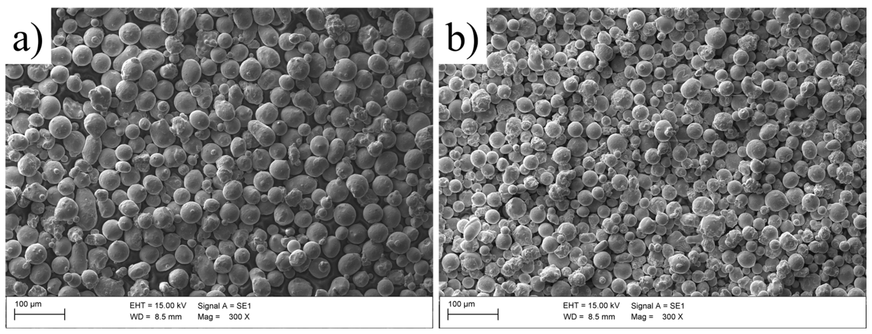
Figure 2.
Sketch of the setup used for experimentation showing the two types of dividers: a) α1-type divider; b) α2-type divider.
Figure 2.
Sketch of the setup used for experimentation showing the two types of dividers: a) α1-type divider; b) α2-type divider.
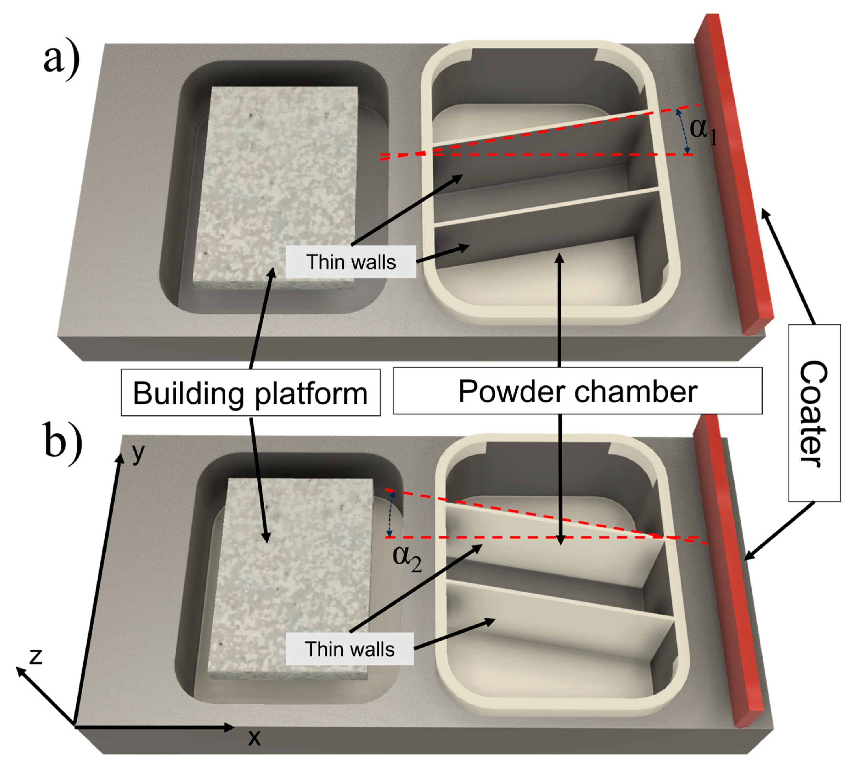
Figure 3.
Schematic representation of specimen composition.
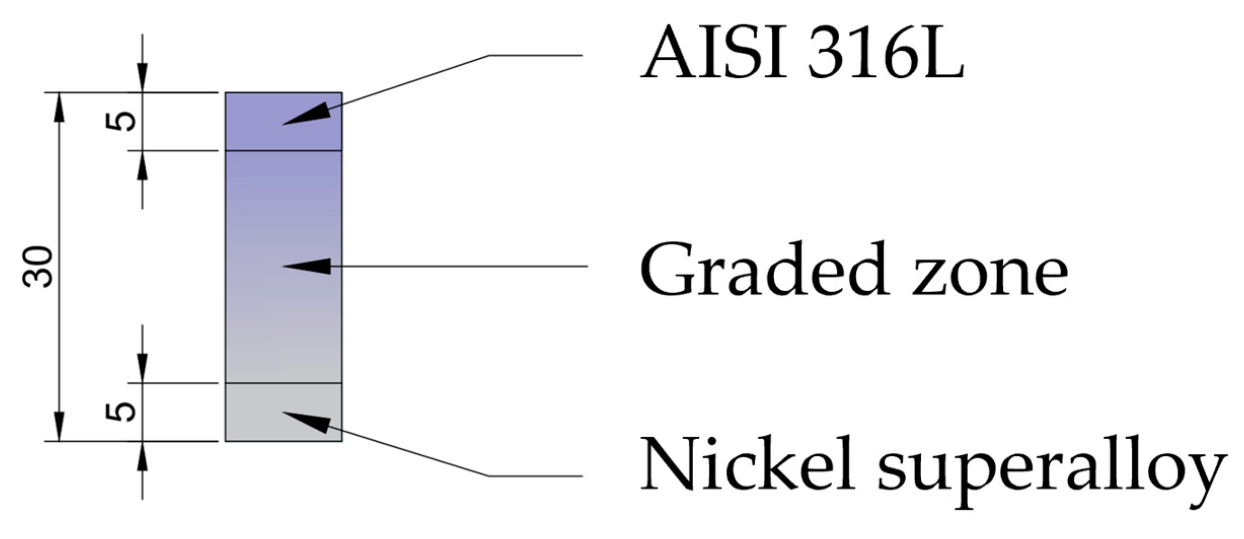
Figure 4.
Sketch of the position of the specimens during their manufacture showing the ID assigned to each of them.
Figure 4.
Sketch of the position of the specimens during their manufacture showing the ID assigned to each of them.
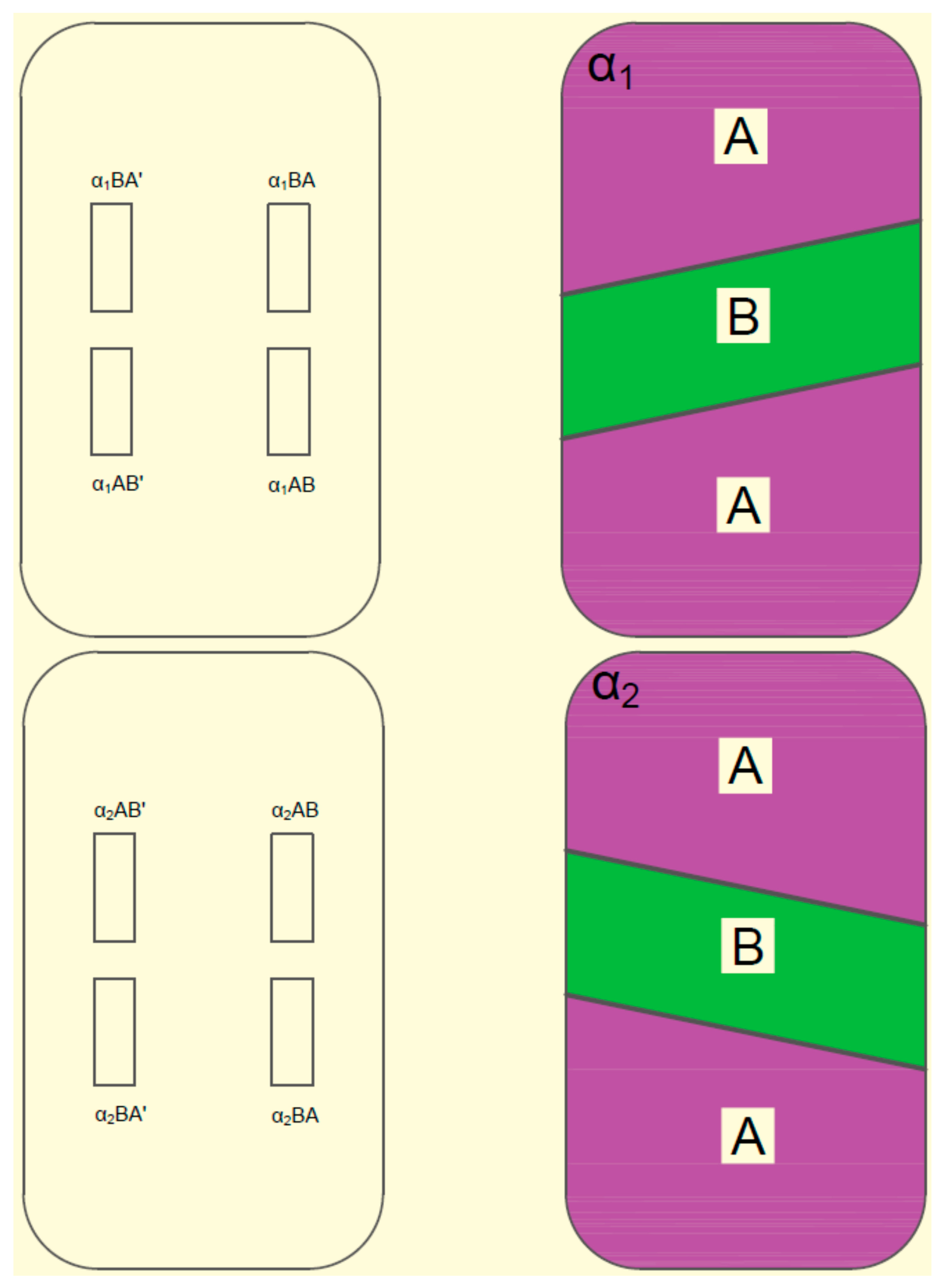
Figure 5.
(a) to (h): Micrographs of the polished surfaces of test specimens 1L, 1T, 2L, 2T, 3L, 3T, 4L, and 4T respectively.
Figure 5.
(a) to (h): Micrographs of the polished surfaces of test specimens 1L, 1T, 2L, 2T, 3L, 3T, 4L, and 4T respectively.
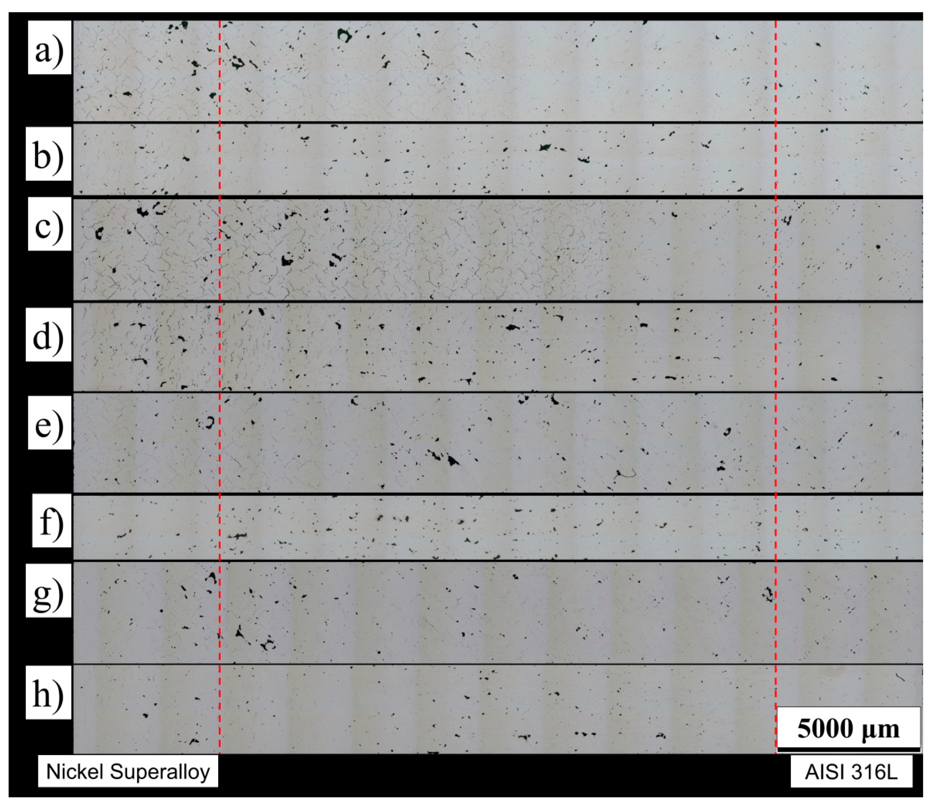
Figure 6.
Distribution of the number of discontinuities along the XY and YZ planes: (a) distribution in the eight specimens, considering the 4 combinations; (b) distribution in specimens 1 and 2; (c) in specimens 3 and 4.
Figure 6.
Distribution of the number of discontinuities along the XY and YZ planes: (a) distribution in the eight specimens, considering the 4 combinations; (b) distribution in specimens 1 and 2; (c) in specimens 3 and 4.
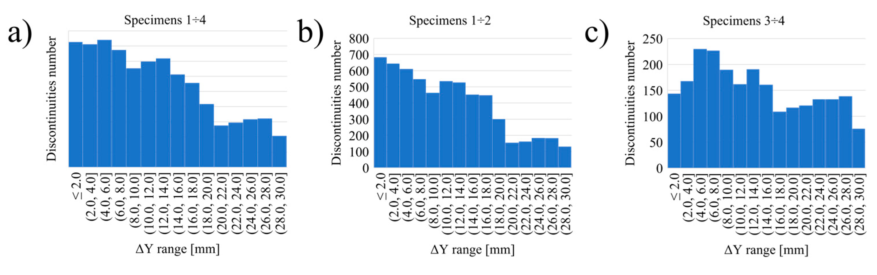
Figure 7.
Images of the microstructure of the analyzed samples: (a) 4L specimen in the AISI 316L zone; (b) 3L specimen in the mixed composition zone; (c) 4T specimen in the nickel superalloy zone.
Figure 7.
Images of the microstructure of the analyzed samples: (a) 4L specimen in the AISI 316L zone; (b) 3L specimen in the mixed composition zone; (c) 4T specimen in the nickel superalloy zone.
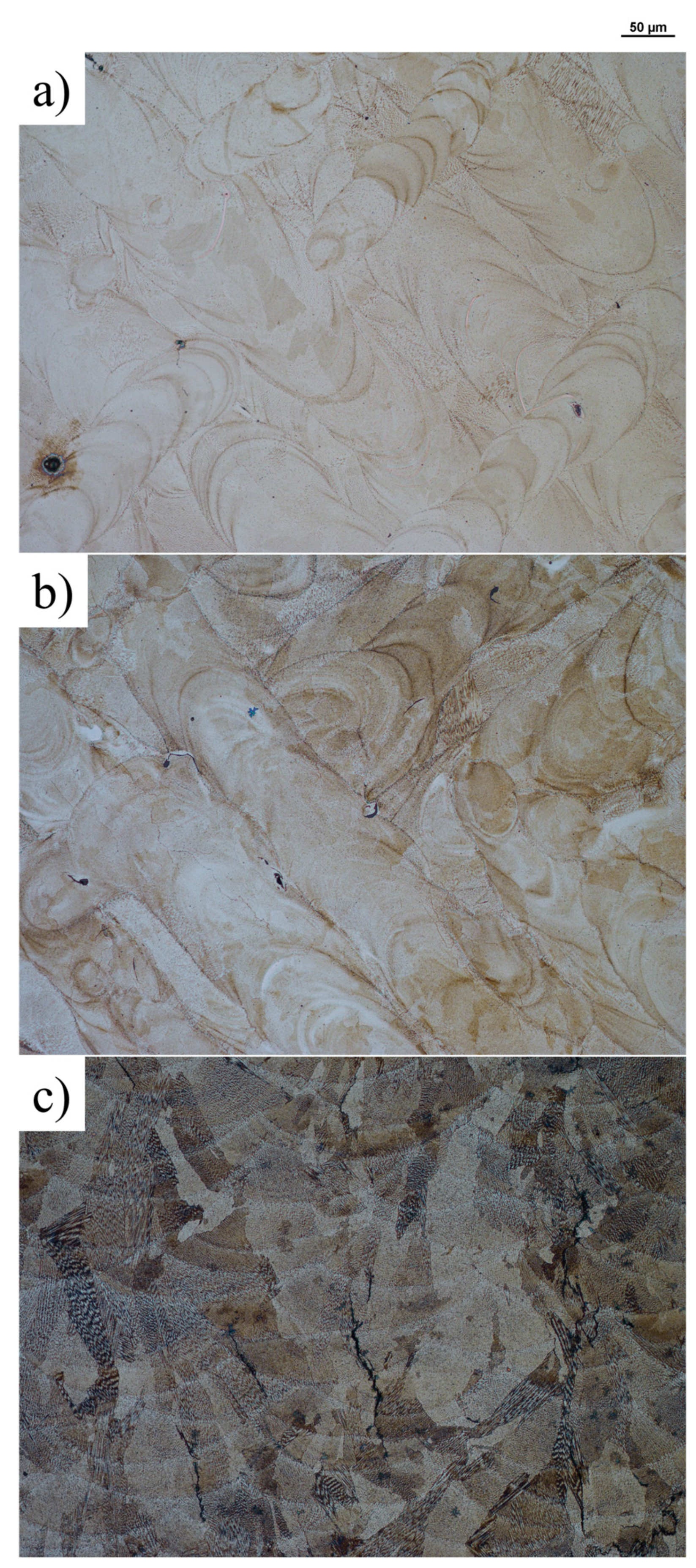
Figure 8.
Schematic diagram of hardness measurement positions on the specimen surface.
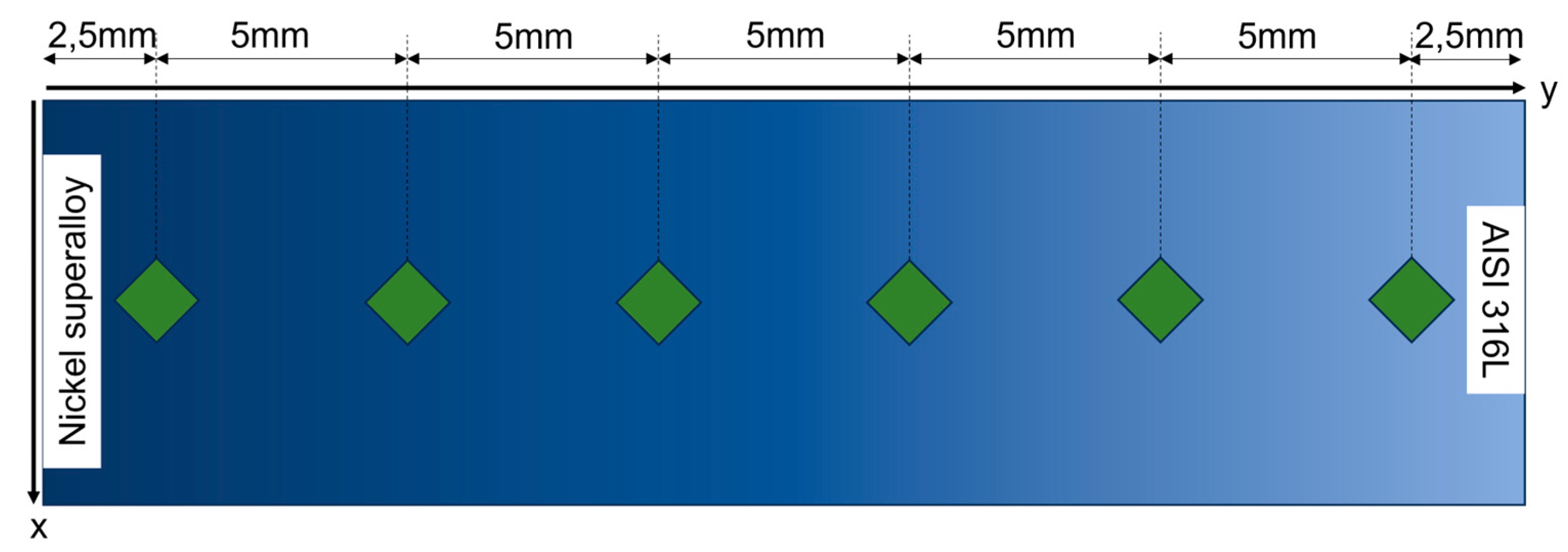
Figure 9.
Comparison of hardness values of specimens with different divider angle: (a) and (c) hardness results of AB-type specimens; (b) and (d) hardness results of BA-type specimens.
Figure 9.
Comparison of hardness values of specimens with different divider angle: (a) and (c) hardness results of AB-type specimens; (b) and (d) hardness results of BA-type specimens.
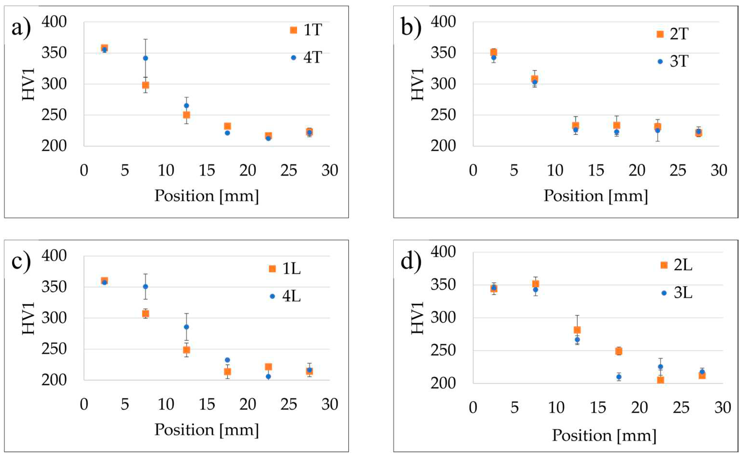
Figure 10.
Comparison of hardness values of specimens with different mutual position of the materials during the distribution of the powder bed: (a) and(c) hardness results of α2 type specimens; (b) and (d) hardness results of α1 type specimens.
Figure 10.
Comparison of hardness values of specimens with different mutual position of the materials during the distribution of the powder bed: (a) and(c) hardness results of α2 type specimens; (b) and (d) hardness results of α1 type specimens.
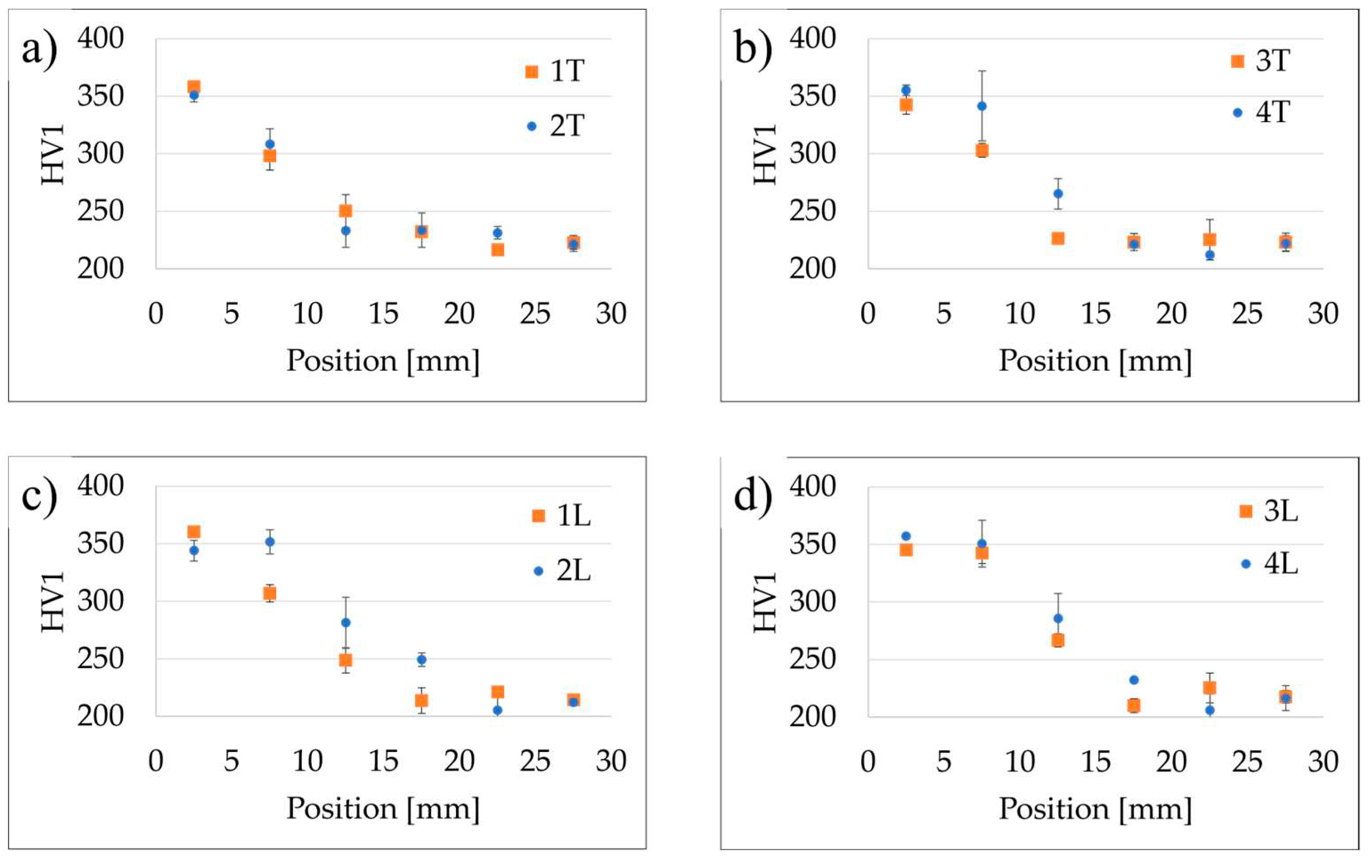
Figure 11.
Results of chemical analysis performed on sample: (a) 1T; (b) 2T; (c) 3T; (d) 4T.
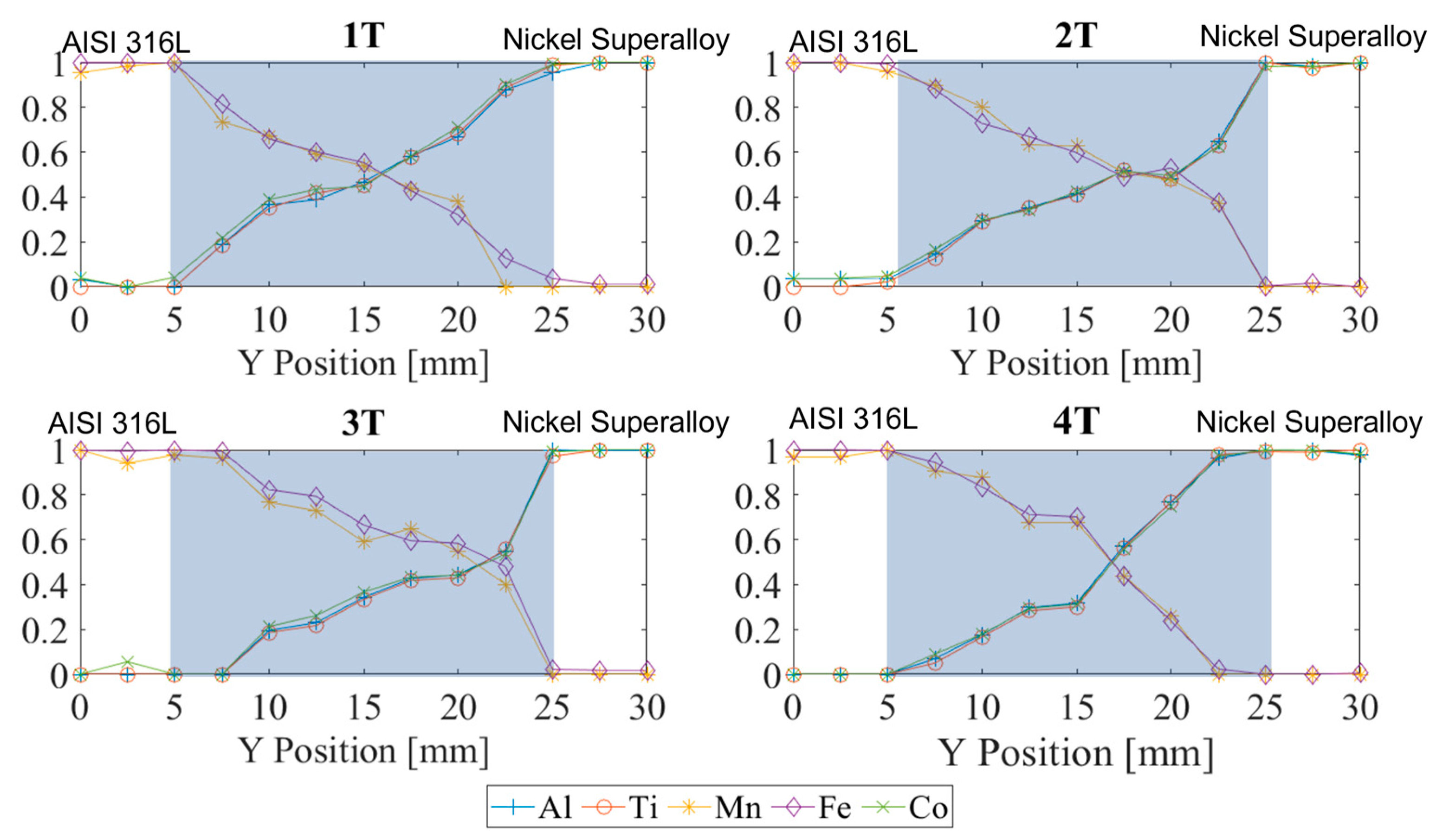

Table 1.
Chemical compositions of the two materials' elements from EDX microanalysis.
| Nickel Superalloy [wt.%] | AISI 316L [wt.%] | ||||||||
|---|---|---|---|---|---|---|---|---|---|
| C | Ni | Cr | Mn | Co | C | Ni | Cr | Mn | Co |
| 0.16 | Bal | 15.60 | - | 10.73 | 0.02 | 10.10 | 16.70 | 1.00 | - |
| Mo | Al | Ti | W | Fe | Mo | Al | Ti | W | Fe |
| 1.20 | 2.98 | 5.17 | 2.11 | - | 2.04 | - | - | - | Bal. |
Table 2.
Metallographic specimen identification.
| Samples ID | Metallographic Specimen ID | Cut Direction |
|---|---|---|
| α1AB | 4T | YZ plane |
| α1AB’ | 4L | XY plane |
| α1BA | 3T | YZ plane |
| α1BA’ | 3L | XY plane |
| α2AB | 1T | YZ plane |
| α2AB’ | 1L | XY plane |
| α2BA | 2T | YZ plane |
| α2BA’ | 2L | XY plane |
Disclaimer/Publisher’s Note: The statements, opinions and data contained in all publications are solely those of the individual author(s) and contributor(s) and not of MDPI and/or the editor(s). MDPI and/or the editor(s) disclaim responsibility for any injury to people or property resulting from any ideas, methods, instructions or products referred to in the content. |
© 2023 by the authors. Licensee MDPI, Basel, Switzerland. This article is an open access article distributed under the terms and conditions of the Creative Commons Attribution (CC BY) license (http://creativecommons.org/licenses/by/4.0/).
Copyright: This open access article is published under a Creative Commons CC BY 4.0 license, which permit the free download, distribution, and reuse, provided that the author and preprint are cited in any reuse.


