
Submitted:
13 July 2023
Posted:
19 July 2023
You are already at the latest version
Abstract
The results of applying drilling engineering tools in planned deviated and horizontal wells of oil and gas condensate fields have been examined. The basis for the implementation of a comprehensive approach was the information obtained from drilling horizontal wells in the West and East Siberia, Volga-Ural region, and Iraqi Kurdistan. A synthetic model is considered as an example of the data, incorporating geomechanical and geological properties. As a result of the conducted audit of the geomechanical model and drilling process, the methodologies used were further developed to obtain optimal drilling fluid densities, aiming to prevent cavity formation on well walls, hydraulic fractures, and other related issues. The implementation of the Python programming language was introduced in the stages of geomechanical model preparation, resulting in a time acceleration of up to 20%. During the pre-drilling stage, technological operations were synchronized with the geomechanical model, increasing the involvement of process participants through the synchronization of knowledge areas. The interrelation between drilling technology, drilling parameters, properties of flushing fluids, and rock stability analysis was established, ensuring a 5% increase in construction speed (through NPT reduction and modification of existing tools and technological operations) and accident-free drilling of complex deviated and horizontal wells, provided that the recommended drilling parameters are followed.
Keywords:
geomechanics
; drilling
; engineering
; technology
; sticking
; mud loss
; pyhton
; programming
; oilfield
Highlights
Developed scripts optimizing the workflow of a drilling engineer in wellbore support using petroleum geomechanics.
Emphasizing the significance of expertise in drilling technology, drilling fluids, and geomechanics among specialists, along with the possession of cross-platform skills to contribute to accident-free drilling.
1. Introduction
With the advancement of well construction technologies, drilling becomes more complex, drilling speed increases, and new components of drilling fluids emerge. In parallel, many oil fields are entering their final development stages, which are accompanied by the emergence of incompatible drilling conditions. Although this issue is not limited to old fields, it leads to numerous challenges both during well construction and during well completion. These complications become a significant factor affecting production profitability. To ensure accident-free drilling operations, adherence to an engineering approach that combines experience, accumulated knowledge, and modern technologies is crucial.
In the scientific and industrial environment, numerous reference manuals and guides on oil and gas engineering have been created [1,2,3,4], providing the necessary information for achieving optimal results in drilling operations. However, assessing working conditions and subsequently executing them at a high professional level also require prudence and sound judgment based on experience and knowledge.
Modern conditions demand professional flexibility, technological adaptability, and the ability to acquire new skills and knowledge from specialists. In this context, the inclusion of experts in the application of digital technologies is particularly important. This article presents an approach to engineering oil and gas well drilling, which requires expertise in drilling fluids, drilling technology, geomechanics, and programming in Python.
2. Preprocessing of Geomechanical Modeling and Analysis of Active Clay Interval
A) The drilling of the well commenced with the use of a 393.7mm bit (Conductor Casing 324 mm). The casing shoe was set at a depth of 361m. The drilling and casing of the interval were carried out without complications. The interval consists of sandstone, and a high-viscosity clay-based drilling fluid was used. Proper selection of the rheological properties of the drilling fluid and drilling parameters is crucial in this interval to prevent lost circulation, sanding, graveling, and thawing of permafrost formations.
B) The drilling of the conductor interval proceeded well with continuous rotation of the drill string in the 361-520m interval (ROP=52 m/h, WOB=0.9 t, BHP=30-65 atm, Qp=48 l/s, dP=5-8 atm, RPM=20 rpm, Torque=0.1 t·m). During this interval (up to a depth of 520m), sand content was observed based on the analysis of the shaker screens, while active clay was encountered below 520m. The drilling in the 520-940m interval was performed under the following regime (ROP=52-70 m/h, WOB=0.9-6 t, BHP=65-95 atm, Qp=48-54 l/s, dP=5-8 atm, RPM=20-40 rpm, Torque=0.1 t·m). Subsequently, a decrease in drilling speed from 60 to 35 m/h was recorded.
Pills (with a detergent) was carried out during the depth progress without interrupting the drilling process. No significant increase in drilled solids was observed on the pills at the surface.
During drilling to a depth of 1067m (ROP=30 m/h, WOB=11 t, BHP=160 atm, Qp=56 l/s, dP=12 atm, RPM=40 rpm, Torque=0.5 t·m), no sticking, pressure fluctuations, or torque build-up were observed.
At a depth of 1067m, an increase in instantaneous mechanical drilling speed up to 60 m/h was observed. Subsequently, the drilling was continued with a mechanical speed of 30 m/h. Upon reaching a depth of 1118m, a decrease in mechanical speed to 5 m/h was observed. The decision was made to perform a trip out of hole for a BHA inspection. During the trip, drag forces of 5-10 t were observed, and the circulation was maintained. The inspection revealed a seal failure on the bit and stabilizer (figure 1). The borehole was properly cleaned to the bottom. A complete replacement of the drilling fluid with a low-clay encapsulated system using calcium carbonate as a weighting agent was performed. Afterward, drilling was resumed to reach the planned target depth of 1422m. The casing of the interval was completed without complications.
Figure 1.
- Shale collar.
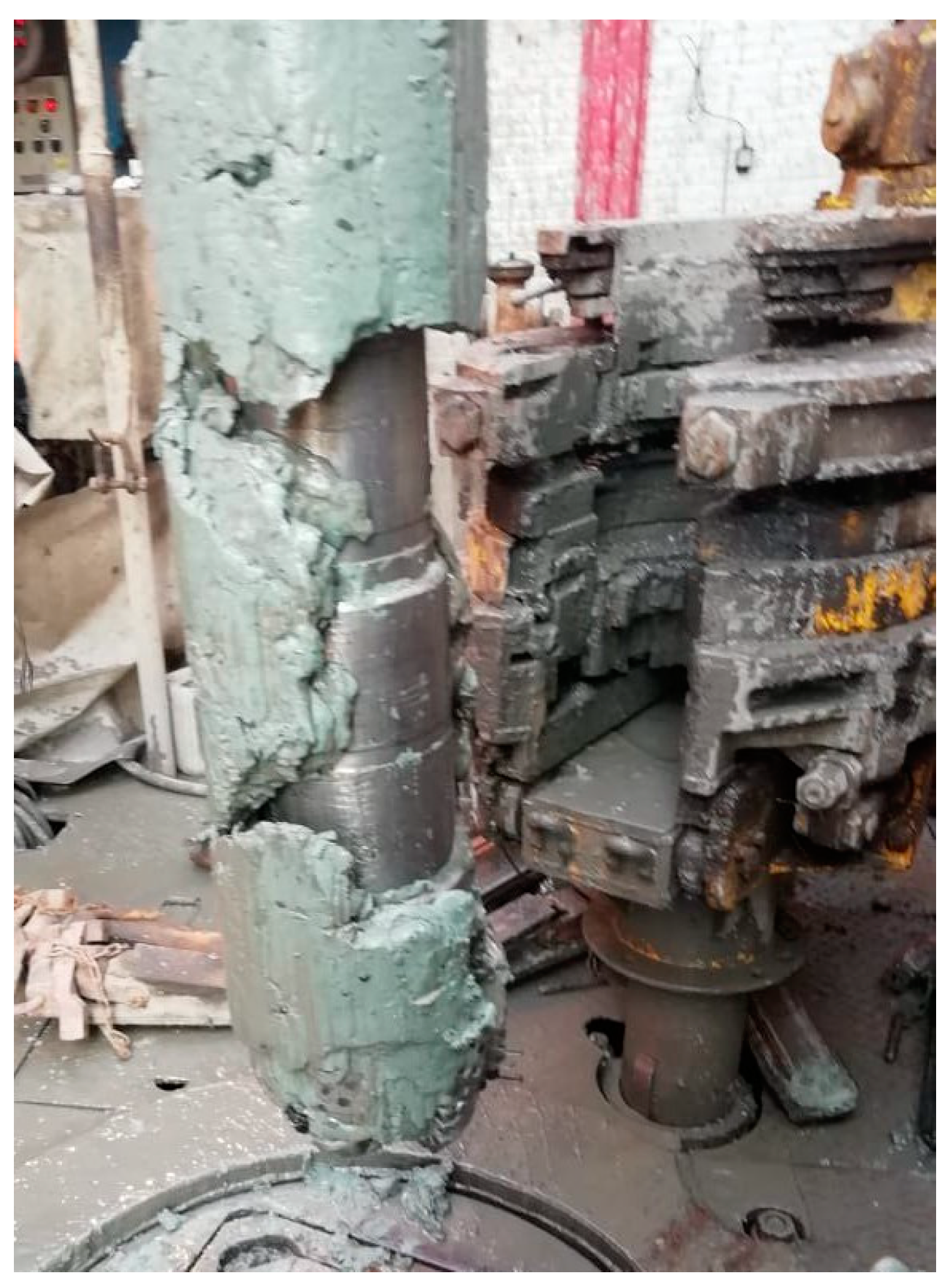
It is worth noting that a PDC bit was utilized with a stabilizer in the BHA. The absence of a geomechanical model in this interval is due to insufficient data for its construction. Incorporating well logging in this interval will enhance the geological understanding of the zone and facilitate pre-drill interval modeling, including lithological models and calculation of rock's geomechanical properties. Based on the drilling journal and circulation pressure changes, it can be inferred that there was a gradual reduction in the drilling fluid viscosity during the drilling process until the encounter of active clays. However, the viscosity reduction alone was insufficient to achieve turbulence in the annular space for effective fluid circulation.
As the drilling operations were conducted correctly from a technological standpoint, with drilling speed limitations, borehole reaming and monitoring of drilling parameters, it was decided to further examine the configuration of the drill string. The verification of the upflow velocity and mud transport velocity was performed using electronic spreadsheets, and they were within the norm. No abnormal weight or torque fluctuations were observed during tripping operations. Moreover, increasing the drilling fluid flow rate could have triggered erosion processes in the overlying sand intervals. The abrupt increase in instantaneous mechanical drilling speed at a depth of 1067m indicates the geological heterogeneity of the interval.
The design of the drill string was typical for the drilling region, and the weight of the BHA complied with the calculated values during drilling. The key aspect in preventing seal failures while drilling through active clay intervals is to maintain an adequate hydraulic horsepower at the bit (HSI), which should be no less than 2 hp/in2. The total flow area (TFA) and pump performance significantly influence the HSI value. Upon examining this potential complication, it was discovered that with the current pump performance, the HSI values at the bit ranged from 1.12 to 1.60 hp/in2. In other words, with the current HSI values (below 2 hp/in2), the desired hydro-monitoring effect at the bit to clean the bottom hole from drilled cuttings was not achieved.
Studying the regional geology of this interval from open sources has led to the conclusion that this interval is predominantly composed of deep-sea marine clays, primarily montmorillonite rich. Since the underlying formation mainly consists of shale, all lithogenesis processes, including geostatic compaction and expulsion of formation water, are more advanced and clearly in the early stages of catagenesis. Retrospective analysis indicates that the use of freshwater-based drilling fluid systems leads to the phenomenon of clay flowability, while the effectiveness of polyacrylamide encapsulators (PHPA) is insufficient. The time spent on unplanned stuck pipe events and additional wellbore conditioning amounted to 22 hours (or 22.3%) out of the planned total construction time for the interval, which was 98.5 hours. An excess in the volume of drilling fluid prepared for the interval was noted.
For drilling these intervals, it is recommended to increase the application of clay inhibitors. Along with polymer, phosphate, polyacrylate, and organic clay-inhibitors, borosilicate clay inhibitors exhibit the highest effectiveness for this type of formation in this geological location. Using them can achieve multiple objectives simultaneously:
- Clay inhibition
- Reduction in the viscosity of the drilling fluid
- Enhancement of the bridging capacity of polymer reagents in forming a low-permeability filter cake
- Minimization of driling mudball on bit and BHA elements
- Improved wellbore cleaning
- Reduction of caving
To optimize the preparation of pre-drill audits, including the calculation of a geomechanical model, it is recommended to utilize automation tools for routine processes. In this case, scripts for working with a distributed folder system and data extraction using Python are proposed. Observations show that during the audit and geomechanical model preparation, the time distribution is roughly as follows:
- Data collection (15% of time)
- Data preprocessing (25% of time)
- Exploratory data analysis (20% of time)
- Geomechanical model calculation (30% of time)
- Validation and interpretation of results (10% of time)
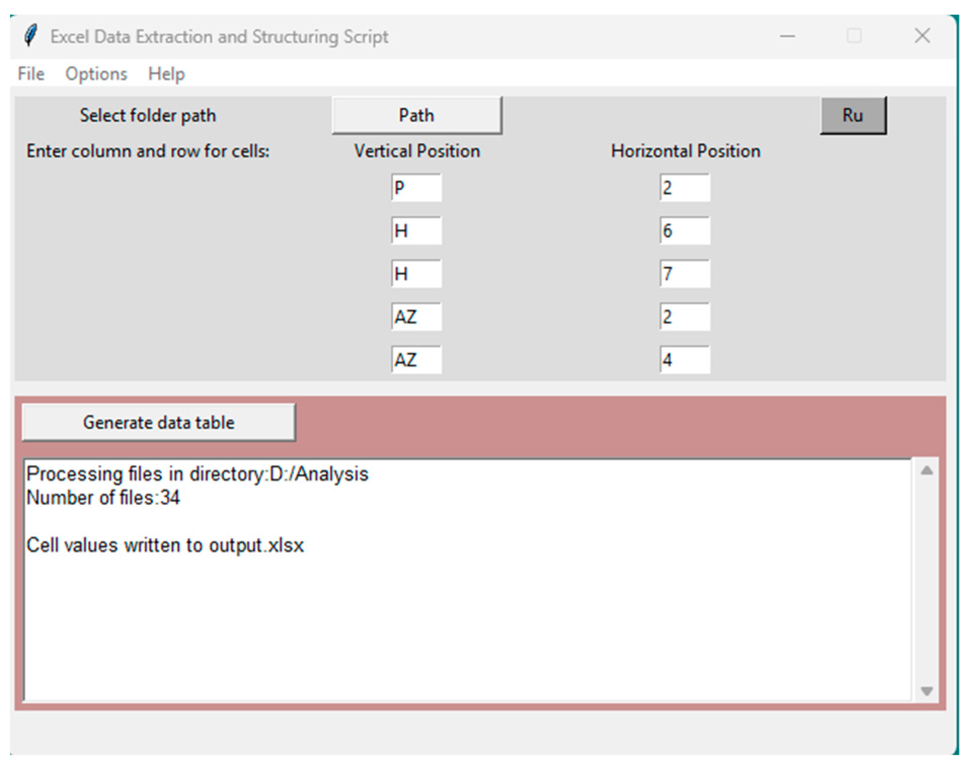
Automating routine work with many Excel spreadsheets can reduce the time needed to create a model by up to 25%. It also increases the accuracy of the data used. The Python scripts [5] performs all the tasks and outputs the results in a tabular file, making it easy to plot depth days and perform further analysis (figure 2, 3).
Figure 2.
- Script for moving files from a directory.
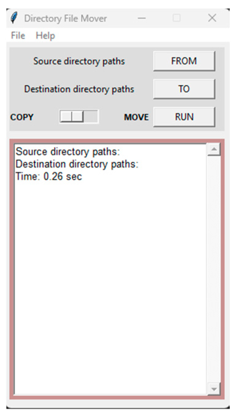
Figure 3.
- Extract data from Excel script.
3. Complication analysis for incompatible drilling conditions
A) Drilling of the interval beneath the production casing was performed in the depth range of 1422-3360 meters. This interval is more responsible. The analysis of complications begins with the examination of the well trajectory. Since assumptions are often made, which can lead to complications:
- The shortest path to the target depth (focusing on lower metal consumption)
- Shallow point of curvature build-up and high rates of zenith angle increase
However, the trajectory encompasses most of the drilling solutions (and problems), such as borehole stability, wear on casing/drill pipes, axial loads, cuttings removal, geological uncertainties, and inclinometric uncertainties.
This interval traverses a zone of incompatible drilling, characterized by a thick cap rock with unstable clay deposits and a highly permeable transit zone with abnormally low reservoir pressure. In this well, we consider a case where the casing string must cover both of these intervals for further drilling below the tailpipe.
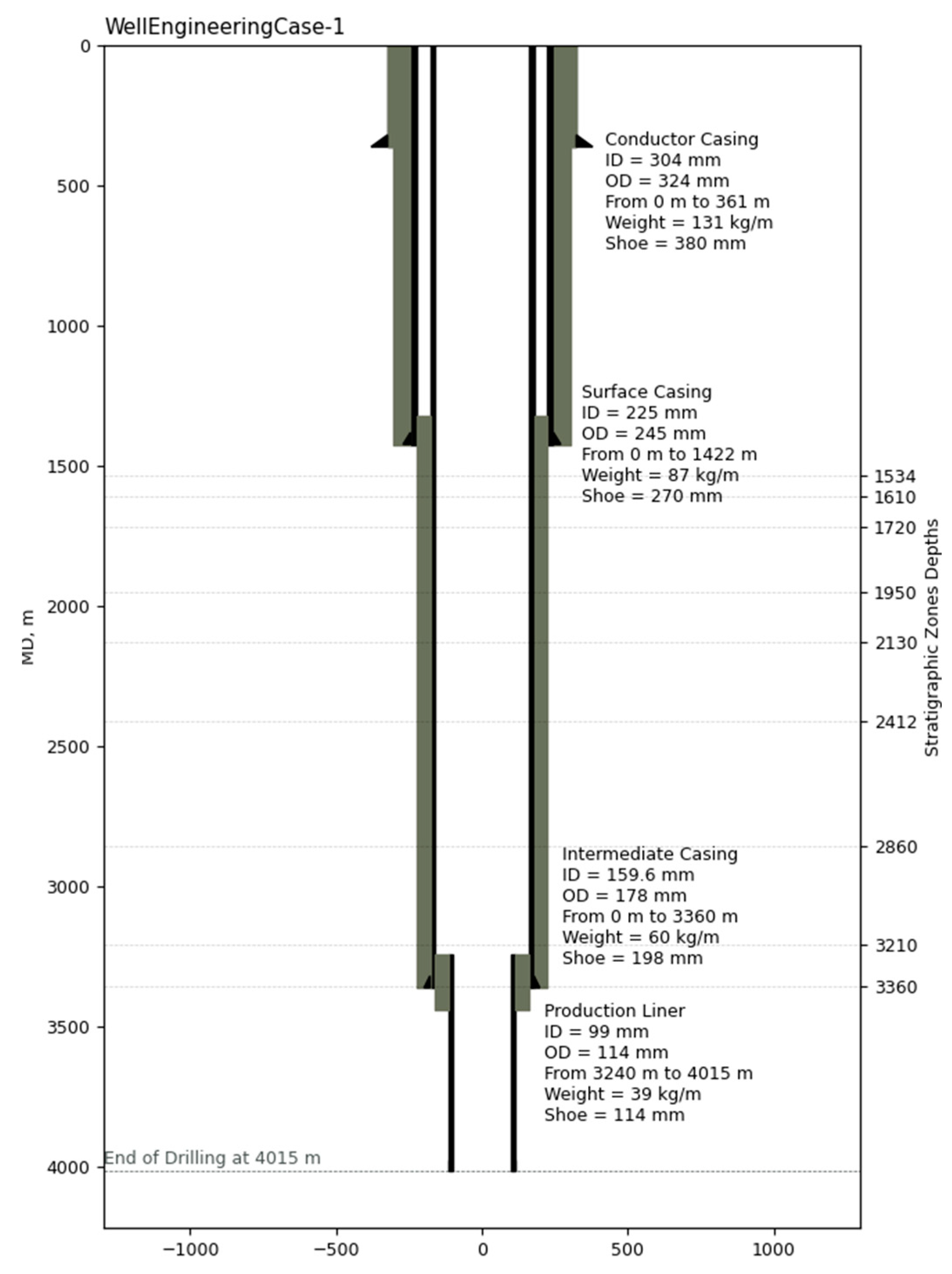
The visualization of the planned wellbore configuration [6] is depicted using the matplotlib Python library (figure 4).
Figure 4.
- Well Design.
When drilling the interval from 1422 to 3243 meters, the BHA consisted of the following components: (Bit: 220.7, Mud Motor: 178 7/81, Caliper: 213, MWD Tool: 178, heavyweight DP: 127, lightweight DP: 147, steel drill pipe: 127).
Drilling within the interval of 1422 to 2830 meters was performed with a single-run drilling, and the average circulation time before making a connection was 3-5 minutes. The tool's performance was trouble-free, and no sticking or overpull events were observed. Borehole cleaning was good according to the drill log.
The drilling parameters were as follows: (ROP=32-55 m/h, WOB=4.3-10.4 t, BHP=79-186 atm, Qp=38-41 l/s, RPM=30-40 rpm, Torque=0.8-1.3 t·m).
With a maximum circulation time of 5 minutes and a pump rate of 41 l/s, the potential for cuttings lifting within the annular space is estimated to be 481 meters. This can lead to difficulties in retaining the cuttings in the wellbore, their agglomeration, and an increase in hydraulic losses.
The drilling within this interval proceeded without any recorded complications. The weight on bit and torque values during rotation corresponded to the calculated values. According to the drilling journal, the average mechanical drilling rate in the interval from 1422 to 2588 meters was 39.9 m/hr.
During drilling in the interval from 1422 to 3243 meters, mud-pills were pumped to clean the wellbore at the following depths:
- 1860 meters with a volume of 5 m3, viscosity of 120 seconds, and density of 1.34 g/cm3.
- 2830 meters with a volume of 5 m3, viscosity of 120 seconds, and density of 1.38 g/cm3.
A slight increase in drilled cuttings was observed wash away operations. The mud density was maintained at 1.33 (+/-0.03 g/cm3) within the interval from 1662 to 2830 meters. Afterward, it was increased to 1.38 g/cm3 according to the geomechanical calculations (figure 5) and the approved work plan. The analysis of the geomechanical model can be performed by verifying the actual drilling data with the previously conducted wellbore stability calculations using Python libraries.
Upon reaching a depth of 3243 meters, the full drilling fluids loss occurred. Under static well conditions, the wellbore losses amounted to up to 1.5 m3/h. The decision was made to change the BHA to a rotary one and carry out pluggin actions to mitigate the losses.
When analyzing any type of drilling complication, it is advisable to refer to drilling diagrams and examine the timing of the occurrence of the complication and the preceding operation.
The maximum equivalent circulating density (ECD) in the absorption zone was 1.60 g/cm3, which does not correspond to the hydraulic fracturing gradient according to the model but matches the onset of the absorption gradient. This value determines the reactivation pressure of natural fractures (if present) or fractures created during drilling. The drilling mechanics data indicates the absence of sharp ECD fluctuations and, consequently, annular pressure surges, suggesting that a fracture could not have formed directly during drilling. Therefore, the absorption could have occurred due to water hammer effects during rapid pump startups. Another contributing factor was the high mechanical drilling rate (up to 55 m/hr) at the time of absorption and relatively low pump rate (up to 41 l/s), which may have hindered effective hole cleaning of a 220.7 mm diameter borehole.
Figure 5.
- Wellbore stability analysis.
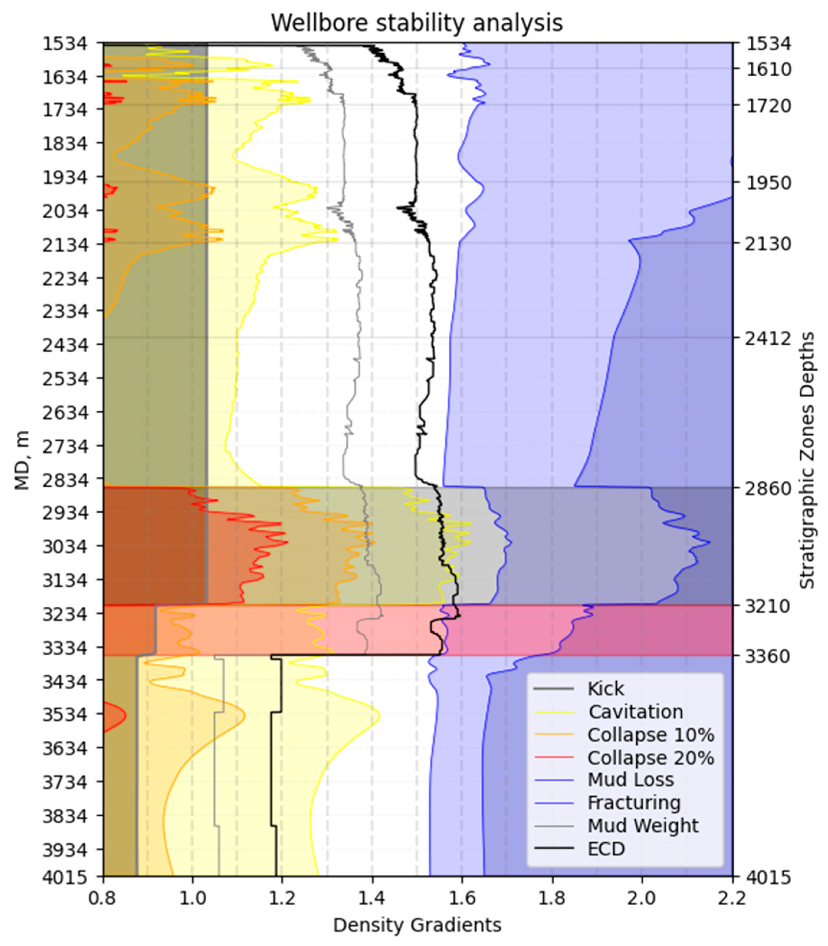
The rotary BHA reaming was uneventful, and no increase in well losses was observed during the round-trip operations. This indicates the closing of the hydraulic auto-fracture. Upon reaching a depth of 3200 meters, circulation was gradually restored from 5 l/s to 25 l/s. Subsequent trip in hole was performed with continuous circulation and the pumping of mud sweeps with materials to combat absorption.
The BHA change for drilling was successfully completed. The target depth of 3360 meters for the section was reached without complications. Open hole logging was performed in the interval from 3360 to 2810 meters without any issues.
The running of the casing string (178 mm) from 0 to 2857 meters proceeded without complications, and the mud filling and weight corresponded to the design calculations. At a depth of 2857 meters, slacking-off of the casing string was observed, resulting in a 6-ton reduction below its self-weight. Circulation was restored afterward. During further descent with circulation, pack-offs of 2-3 tons were observed. While running the casing shoe to a depth of 3208 meters, mud loss with an intensity of up to 5 m3/h was recorded. Circulation was stopped, and the casing running continued. There was a sidewall sticking of casing at a depth of 3340 meters. The inability to run casing was 20 meters, and the decision was made to perform a cementing operation using the reverse cementing method from the current depth. The time spent on BHA change and absorption mitigation was 48 hours, resulting in a 3-hour extension of the casing attachment time. The cumulative non-productive time (NPT) was 51 hours (13%). The planned time for this interval was 389 hours, with a total of 984 hours for the entire well.
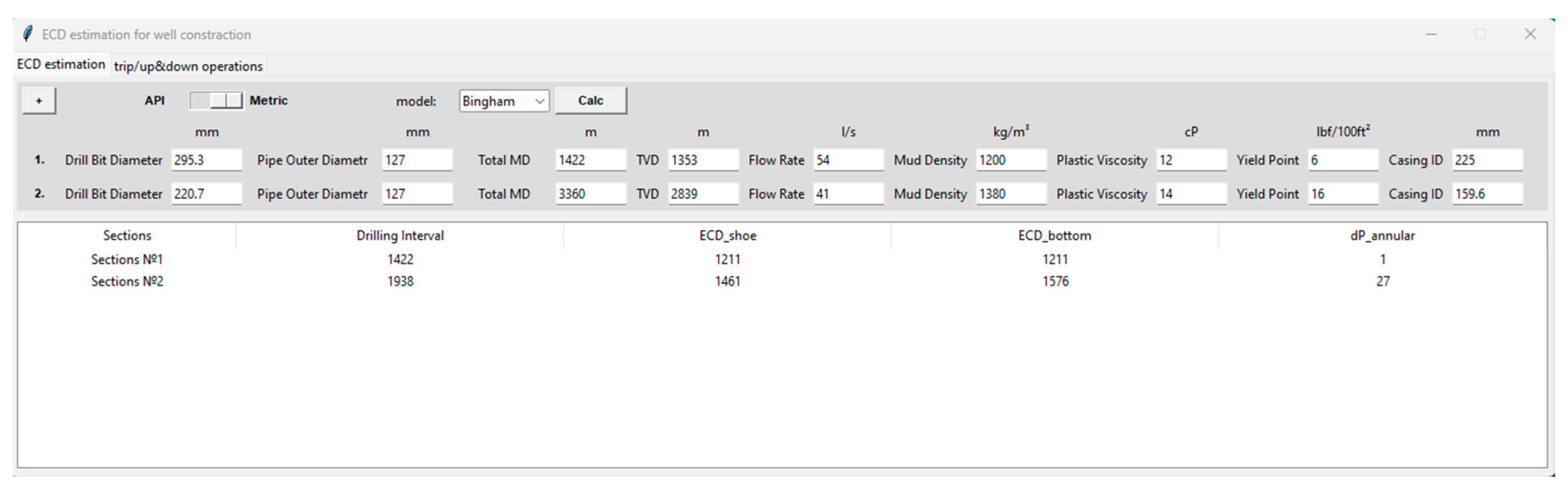
Open-source Python libraries were used for constructing a 3D wellbore trajectory, visualizing areas of intense parameter curvature [5], and conducting hydraulic calculations (figure 6). An estimated ECD curve was added to the stability analysis tablet depicting the wellbore stability calculation (figure 5).
Figure 6.
- ECD estimation script.
As well as visualising the resulting complications (figure 7, 8).
Figure 7.
- Graphic script interface for visualising well complications.
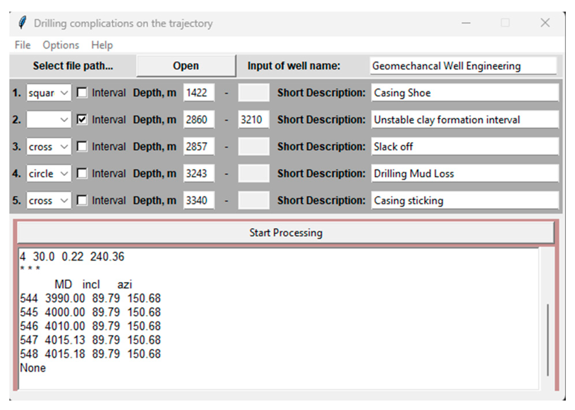
Figure 8.
- 3-D projection of the well trajectory with visualization of borehole complications.
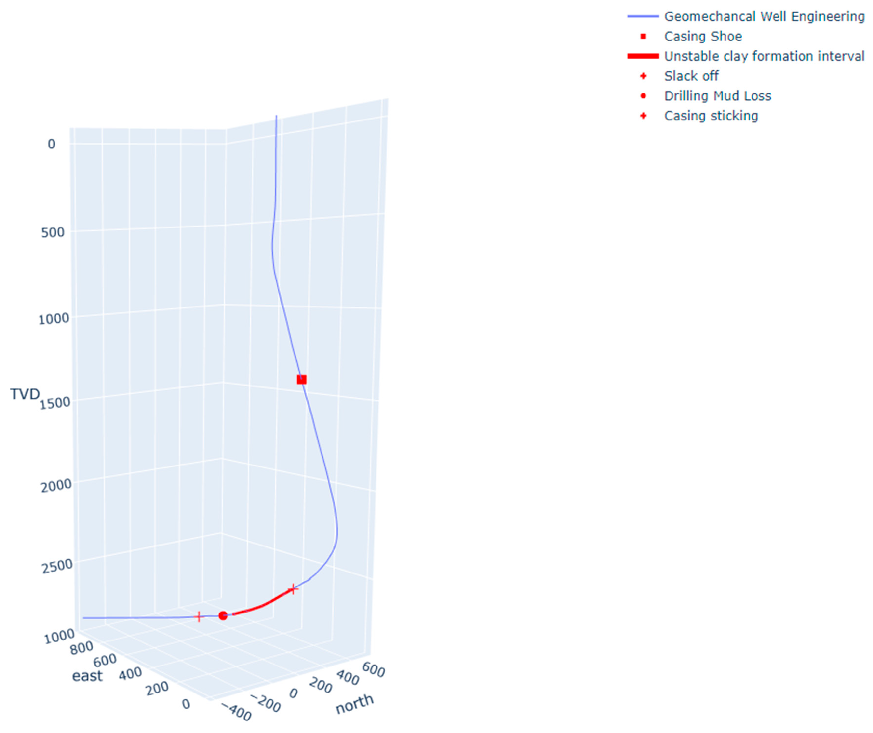
Since the wellbore angle within the challenging interval exceeds 65 degrees, the stability factors of the 2860-3210m interval, predominantly composed of argillites, are exacerbated. The decrease in hydrostatic pressure in the wellbore during the absorption of drilling fluid could initiate the collapse of the wellbore walls. Unloading of the casing started precisely within this interval during the descent of the drill string. However, significant complications were not observed in this interval throughout the drilling process and after changing the drilling mud system to address the absorption issue. In this case, it is advisable to consider the temporal factor, but analyzing it requires a larger sample of wells and deeper geomechanical studies of the interval's rocks. The primary problem here was initially the absorption of drilling fluid, followed by the casing sticking in the transit zone with abnormally pressured formation.
There was a potential for wellbore collapse in the interval of unstable clayey deposits. Therefore, considering the combination of factors, it can be concluded that in this situation, the accumulation of cuttings in the wellbore occurred during drilling operations (due to insufficient wellbore cleaning and cave-in debris), but the volume of cuttings was not critical for running a completion string. This subsequently triggered the absorption of drilling fluid and casing sticking. To confirm this hypothesis, equivalent circulating density calculations were performed using a Python script.
A modern oilfield service company specializing in drilling fluids possesses an extensive arsenal of measures to combat fluid losses. Lost circulation materials form the basis of, and key to, successful lost circulation control. In situation when lost circulation control traditional technology has not effectively solved the challenge of drilling fluid losses, needed new deeper way. This paper systematically summarises the mechanisms of drilling fluid loss in fractured formations. Study of the lost circulation mechanism in fractured formation, lost circulation control mechanism in fractured formation (stress cage theory, fracture closure stress theory, fracture extension stress theory, chemical reinforcement wellbore theory) can provide effective problem solving and facilitate trouble-free drilling well [7]. Mastering these tools in the context of using programming languages can contribute to a significant reduction in the cost of field development complex. The necessity of their application calls for a rational approach to prevent the exacerbation of complications or the wasteful expenditure of resources.
In the presence of incompatible drilling conditions, relying solely on drilling experience is not advisable. Such experience is like reinforcement learning in machine learning and is too costly in practice. It is important not to rely solely on primary signs of complications but to evaluate the situation from various perspectives.
The main arguments for using a similar wellbore design are typically as follows:
- Economic constraints in the metal capacity of a high-tech bottomhole assembly design necessitate the use of additional packers for isolating the transit zone with abnormal formation pressure.
- There is no historical experience of tool sticking and packer failure (or they are very rare) in the productive reservoir in the field. Therefore, concerns about BHA sticking with rotary steerable systems in the transit zone with abnormal formation pressure prevail.
To drill through incompatible zones, it is possible to develop a general approach with the following recommendations. To enhance mutual understanding among drilling process participants, it is necessary for everyone on the rig to have a clear understanding of the overall operations mechanism. For this purpose, drilling geomechanics support services utilize roadmaps where stability calculations, wellbore construction data, and technological parameters are synchronized to create a unified and comprehensible document for reference.
Careful selection of drilling fluid inhibitors (e.g. organic inhibitors, gilsonite, asphaltenes) is recommended as a preventive measure to reduce the risk of collapse of unstable clayey formations. Nanocomposites are also widely used in drilling fluids.
In recent years, several studies have been conducted on the applications of numerous nanocomposites in drilling fluids, such as polyacrylamide/clay nanocomposite [8], nanocarboxymethylcellulose/polystyrene core-shell nanocomposite [9], polymer nanocomposite [10], nanosilica-polymer composite [11], TiO2-polyacrylamide [12], clay nanocomposite [13], ZnO-clay composite and ZnO-Am nanocomposite [13,14]. The results of these studies showed a homogeneous dispersion of nanocomposites in the drilling fluids to perform multiple functions simultaneously, such as fluid loss control, high thermal stability, improved rheological performance and reduction of mud cake thickness.
The various effects of nanocomposites on mud properties are discussed in more detail in the article [15]. The authors demonstrate the use of nanocomposites in drilling operations with their significantly enhanced performance and functionality.
In addition, the inclusion of a circulating sub in the downhole assembly would facilitate absorption mitigation without requiring a change in configuration. The installation of a wellhead pressure sensor for continuous monitoring of equivalent circulating density is also recommended. The use of sodium silicate packs (localised squeeze) or alternative means of reducing rock permeability is recommended to improve the stability of the transit zone at abnormal formation pressures. These recommendations are specific to the case described.
However, the key takeaway from this case is the practice of integrating geomechanics and drilling technology. In such cases, the synergy between science and production plays a crucial role in successful well construction. It is important to emphasize that the use of digital technologies aimed at early detection of drilling complications is universally applicable in terms of algorithm development but requires specialization based on the qualitative characteristics of individual fields. Therefore, the development of such tools is a priority for the industry's future development.
The horizontal interval of the wellbore at 3340-4015m, using a biopolymer drilling fluid with a density of 1.05 g/cm³ for primary wellbore penetration, was drilled without significant complications, although there were difficulties in reaching downhole weight on bit. Oil and other lubricating additives were utilized. The drill string was run to the planned depth, and during the descent, seating was observed, necessitating circulation.
It should be noted that high axial loads on the completion equipment carry the risk of premature tool activation or failure to actuate. Therefore, the use of polymer microspheres for cementing operations in highly deviated horizontal wellbores and careful control of string weights are recommended.
The need for continuous improvement in the approach to drilling operations is dictated by ongoing technological advances. The widespread use of artificial intelligence and machine learning technologies is a challenge for oil and gas professionals. The issue of adapting to the new reality lies in the deep integration of engineering and technical staff with digital tools. The authors have therefore developed a system for monitoring and controlling wells using AI. In the article describe explored a real-time solution that anticipates drilling events and avoid delays caused by such issues as poor hole cleaning, higher torque and drag, swab and surge, stuck pipe, lost circulation, formation damage and wellbore instability. This is important if drilling optimisation is a major technical and corporate goal or if you wish to go beyond the traditional approach of collecting real-time data only to monitor operations. This paper includes robotic drilling automation, aimed at reducing invisible loss time, enhancing drilling efficiency and safety by applying operational safeguards to the drilling control system, providing automatic safety mechanisms and enabling automatic sequences [16].
4. Conclusion
1. A software toolkit has been developed using open-source libraries of the Python programming language, which is efficient in handling various geological objects, flexible to changes, and convenient for customization according to the specified task.
2. Assessments were conducted, yielding the following results:
a. Risk assessment of complications should be carried out prior to drilling, employing a comprehensive engineering approach that incorporates knowledge of geomechanics, hydraulics, drilling fluid chemistry, and drilling technology.
b. Evaluating the risk of losses plays a crucial role in well construction planning to prevent schedule delays and cost overruns.
c. Prompt incident response during drilling operations necessitates the availability of established personnel action algorithms and entails the application of modern digital technologies for risk monitoring and machine learning models for early detection of complications, as well as for solving geological and geomechanical tasks.
3. The following technical conclusions have been made during the work:
a. Accumulation of drilled cuttings in the wellbore often occurs during drilling operations, and the volumes of drilled cuttings may not be critical for well construction using drill string columns. However, the risks of fluid losses and sticking of drilling tools/casing strings increase in subsequent stages.
b. Careful selection of inhibitors should be performed in accordance with the geological section.
c. Expanding the points of intersection between the geomechanical model and drilling technology enhances the understanding of geomechanics among drilling process participants, increases their involvement and interest in well construction, and contributes to incident-free wellbore operations.
d. Implementing Python scripting improves the speed and accuracy of geomechanical calculations and sets the stage for developing incident prevention safeguards.
References
- Lake, L. W. (Ed.) . (2007). Petroleum Engineer's Guidebook. Volume II: Drilling Engineering. S: Houston, TX.
- Bridges, K. L. (2000). Completion and Workover Fluids. Society of Petroleum Engineers.
- Mitchell, J. (2001). Trouble-Free Drilling. Drilbert Engineering, Incorporated.
- Robert, F. Mitchell, Stefan Miska (2011). Society of Petroleum Engineers.
- Stanislav Nikulin. GitHub Profile [Online]. GitHub Profile. Available online: https://github.com/Devenir-Glorieux/.
- Rahmat Ashari. “wellArchitectureDesign”. GitHub repositories. Available online: https://github.com/fraclad/wellArchitectureDesign.
- Yang, J., Sun, J., Bai, Y., Lv, K., Zhang, G., & Li, Y. (2022). Status and Prospect of Drilling Fluid Loss and Lost Circulation Control Technology in Fractured Formation. Gels, 8(5), 260. 5. [CrossRef]
- Jain, R.; Mahto, V. Evaluation of polyacrylamide/clay composite as a potential drilling fluid additive in inhibitive water based drilling fluid system. J. Pet. Sci. Eng. 2015, 133, 612–621. [Google Scholar] [CrossRef]
- Saboori, R.; Sabbaghi, S.; Kalantariasl, A.; Mowla, D. Improvement in filtration properties of water-based drilling fluid by nanocarboxymethyl cellulose/polystyrene core-shell nanocomposite. J. Pet. Explor. Prod. Technol. 2018, 8, 445–454. [Google Scholar] [CrossRef]
- Ahmad, H.M.; Kamal, M.S.; Hussain, S.M.S.; Al-Harthi, M. Synthesis of novel polymer nanocomposite for water-based drilling fluids. In Proceedings of the 35th International Conference of the Polymer Processing Society; AIP Publishing LLC: Melville, NY, USA; 2020. [Google Scholar]
- Mao, H.; Qiu, Z.; Shen, Z.; Huang, W. Hydrophobic associated polymer based silica nanoparticles composite with core-shell structure as a filtrate reducer for drilling fluid at utra-high temperature. J. Pet. Sci. Eng. 2015, 129, 1–14. [Google Scholar] [CrossRef]
- Sadeghalvaad, M.; Sabbaghi, S. The e_ect of the TiO2/polyacrylamide nanocomposite on water-based drilling fluid properties. Powder Technol. 2015, 272, 113–119. [Google Scholar] [CrossRef]
- Abdo, J.; Zaier, R.; Hassan, E.; Al-Sharji, H.; Al-Shabibi, A. ZnO-clay nanocomposites for enhance drilling at HTHP conditions. Surf. Interface Anal. 2014, 46, 970–974. [Google Scholar] [CrossRef]
- Aftab, A.; Ismail, A.R.; Khokhar, S.; Ibupoto, Z.H. Novel zinc oxide nanoparticles deposited acrylamide composite used for enhancing the performance of water-based drilling fluids at elevated temperature conditions. J. Pet. Sci. Eng. 2016, 146, 1142–1157. [Google Scholar] [CrossRef]
- Ikram, R., Jan, B. M., Vejpravova, J., Choudhary, M. I., & Chowdhury, Z. Z. (2020). Recent Advances of Graphene-Derived Nanocomposites in Water-Based Drilling Fluids. Nanomaterials, 10(10), 2004. [CrossRef]
- Barhate Abhijit, Patel Piyush, Abrahamsen Egil (2019) Real-time drilling optimisation – driving drilling excellence. The APPEA Journal 59, 196-210. [CrossRef]
Disclaimer/Publisher’s Note: The statements, opinions and data contained in all publications are solely those of the individual author(s) and contributor(s) and not of MDPI and/or the editor(s). MDPI and/or the editor(s) disclaim responsibility for any injury to people or property resulting from any ideas, methods, instructions or products referred to in the content. |
© 2023 by the authors. Licensee MDPI, Basel, Switzerland. This article is an open access article distributed under the terms and conditions of the Creative Commons Attribution (CC BY) license (http://creativecommons.org/licenses/by/4.0/).
Copyright: This open access article is published under a Creative Commons CC BY 4.0 license, which permit the free download, distribution, and reuse, provided that the author and preprint are cited in any reuse.


