
Submitted:
21 June 2023
Posted:
21 June 2023
You are already at the latest version
Abstract
A simulation test system for the two-dimensional (2D) fuze overload loading process was designed to address the loading issues of recoil overload and centrifugal overload in fuze safety and arming (S&A) devices. By incorporating centrifuge rotation energy storage, impact acceleration simulation, and equivalent centrifugal rotation simulation, a block equipped with a fuze S&A device was accelerated instantly upon being impacted by a centrifuge-driven impact hammer, simulating recoil overload loading. The impact hammer was retracted instantaneously by adopting an electromagnetic brake, which resulted in the centrifugal rotation of the block around its track, to simulate the centrifugal overload loading. The dynamic equations of the simulation test system and the equations of impact hammer motions were established, whereby the rotation speed of the centrifuge and the braking force of the electromagnetic brake were calculated and selected. A dynamic model of the collision between the impact hammer and block was established using ANSYS/LS-DYNA software for simulation analysis. The acceleration curves of the recoil overload and centrifugal overload with variations in the centrifuge speed, cushion material, and buffer thickness were obtained, which verified the feasibility of the proposed loading simulation method. 2D overload loading simulation tests were performed using the developed simulation system, and the acceleration curves of the recoil overload and centrifugal overload were measured. The test results indicated that the proposed system can accomplish 2D overload loading simulations for a recoil overload of several 10000 g and centrifugal overload of several 1000 g.
Keywords:
fuze MEMS S&A device
; recoil overload
; centrifugal overload
; simulation test
1. Introduction
Fuze is the ultimate actuator for weapon systems to exert terminal damage effects, and its safety and reliability directly determine the success or failure of weapons[1,2,3,4]. An essential field of microelectromechanical systems (MEMS) application in fuze is MEMS safety and arming (S&A) devices[5,6,7,8,9]. MEMS S&A devices are significant components of fuze, and their sensitivity to the environment determines the reliability of the fuze function[10,11]. During the launching of shells, MEMS S&A devices are continuously loaded in two-dimensional (2D) overload conditions with high-impact recoil overload and high-centrifugation rotation overload[12,13,14]. Once abnormal overload occurs, the arming process may occur early, resulting in danger conditions and possible misfire[15,16,17]. To conduct ground tests on the performance of fuze S&A devices and ensure their reliability, it is necessary to investigate simulation methods for the continuous 2D loading process with recoil high-impact overload and rotation high-centrifugation overload[18,19].
Peng Wang[20] designed a simulation system for 2D overload loading on MEMS S&A devices, in which the acceleration magnitude and loading time can be adjusted within a certain range by changing the motor speed and torque of the torsion spring. Hongjun Xiang[21] designed a centrifugal testing machine that simulates the dual environmental forces during fuze launching by installing a motor on the horizontal arm in the rotation shaft to enable its autorotation. Junli Zhao[22] and Weijun Zhong et al.[23] investigated the internal ballistics of gas cannons. They simulated the dynamic overload conditions of fuze by adjusting the chamber pressure during the firing process of gas cannons. Yanbing Zhang et al.[24,25,26] designed a compound centrifuge with a vector turntable started by the boosting of air cannons. In their design, the centrifuge is initiated instantly by launching air cannons to boost the rotation arm, and the vector turntable is driven by a servomotor simultaneously; thus, the launching and maneuvering flight processes of missiles are simulated. Using the impact-rotation method, Qingxi Yang[27] investigated the firing approach for arming fuze, established a collision model of instant and inertial firing, simulated the collision firing process, and conducted a performance test of fuze firing by adopting this method. Haiying Qian[28] and Man Xu[29] adopted the impact-rotation method to investigate the relationship between the performance parameters of fuze liquid storage batteries with respect to the recoil force and rotation speed. Chen Lin[30] designed a test set involving a multi-stage induction coilgun with a rotary tube to simulate the dual conditions of recoil and rotation during fuze launching. As indicated by the literature, the current simulation test sets not only suffer from complex configurations, large volumes, and high costs but also can only perform overload loading with a small magnitude. With a focus on MEMS S&A devices of 20mm small-caliber projectiles, the objective of this study was to develop a method for simulating the continuous 2D fuze overload loading.
2. MEMS S&A Device
2.1. Basic Composition of MEMS S&A Device
The basic composition of a MEMS S&A device for 20-mm small-caliber projectiles is illustrated in Figure 1. According to the functions of the components, it can be divided into a recoil protection releasing unit and a centrifugal protection releasing unit[31]. The former utilizes the recoil force from projectile launching to release the movement constraints on the centrifugal explosion-proof slider, to release the recoil protection of MEMS S&A devices. The latter adopts the rated centrifugal force from projectile rotation to relieve the isolation effect of the centrifugal explosion-proof slider on the detonation sequences, thereby releasing all the protections in the system.
2.2. Environmental Forces in Chamber of MEMS S&A Device
During the launch process, the axial velocity of the projectile rapidly increases to hundreds of meters per second under the chamber gas pressure generated by propellant combustion. Meanwhile, the MEMS S&A device is subjected to considerable launch recoil. The recoil slider overcomes the spring tension and moves downward. When it reaches the bottom, the clamping head on the recoil slider enters the clamping holder on the recoil safety unit and is constrained from resetting by the holder, releasing the first protection of the system (recoil protection). Because of the rifling in the barrel, the axial velocity of the projectile squeezed into the barrel rapidly increases to several 1000 or even 10000 rotations per minute (r/min). Accordingly, the MEMS S&A device is also subjected to considerable centrifugal force. Under the centrifugal force, the centrifugal explosion-proof slider overcomes the spring tension and moves outward, and it is then fixed by the clamping holder on the centrifugal protection unit. The explosion-proof effects on the detonation sequence are then relieved, completely releasing the protections of the system (centrifugal protection). The forces and movements of the functional units in a MEMS S&A device are presented in Figure 2.
3. Simulation Method for 2D Overload Loading
3.1. Principle of Equivalent Similarity Simulation
According to the previous description, during projectile launching, the recoil slider in MEMS S&A devices moves downward along the projectile axis, and the centrifugal explosion-proof slider moves outward along the radial direction. A reference object is established by adopting the substrate of the MEMS S&A device. According to the reference, the recoil slider is constantly subjected to a downward force, while the centrifugal explosion-proof slider is constantly subjected to an outward lateral force. Therefore, according to the principle of equivalent similarity, the recoil environmental force during projectile launching can be simulated using the impact acceleration method, and the lateral force on the centrifugal explosion-proof slider can be simulated using equivalent centrifugal rotation (because the rotation speed of projectiles can reach several 104 r/min and because of the limitations of dynamic balance factors and motor speed, it is difficult to directly simulate projectile autorotation). The advantage of this method is that the rotation speed can be reduced by increasing the centrifugal radius. A schematic of the equivalent centrifugal rotation simulation is shown in Figure 3.
3.2. Simulation Test System
As shown in Figure 4(a), the simulation test system for 2D continuous overload loading mainly includes a centrifuge, a collision setup, a circular track, and an acceleration tester. The centrifuge is composed of a rotary table, a main shaft, and a motor with variable frequency and adjustable speed, as well as a bench. The collision setup is installed beneath the rotary table, and the latter is located in the same horizontal plane as the circular track. The block, which is equipped with a MEMS S&A device and an acceleration tester, is placed in a circular track and remains stationary.
As shown in Figure 4(b), the collision setup is the core component of the simulation test system, mainly including a limit groove, an impact hammer, wire rope, a cylinder, a brake disc, and an electromagnetic brake. The limit groove is fixed beneath the centrifugal rotary table, while the impact hammer is inserted into the limit groove and can perform reciprocating telescopic motions. The wire rope is wound around the cylinder with one end fixed on the cylinder and the other connected to the impact hammer. The cylinder and rotary table are assembled coaxially and matched via a tooth–groove structure, allowing relative rotation within a certain angular range. The brake disc is fixed at the bottom of the cylinder, and two electromagnetic brakes are installed symmetrically on the two sides of the brake disc with independent controlling functions.
3.3. Working Process of Simulation Test System
3.3.1. Energy-Storage Process in Centrifuge
Before testing, the block equipped with the test piece of the MEMS S&A device is placed in the circular track and remains stationary with electromagnetic brake A locking the brake disc and electromagnetic brake B remaining loose. The variable-frequency motor is started and drives the centrifugal rotary table via the main shaft. Owing to the locking effect on the brake disc fixed with the cylinder, the cylinder is inhibited from rotating and remains stationary. Therefore, relative rotation occurs between the cylinder and the centrifugal rotary table. As the wire rope winds around the cylinder, the impact hammer is pulled back to the bottom of the limit groove. As shown in Figure 5, after the rotary table turns to a certain degree, its rotation becomes limited. As the torque output of the motor increases constantly, the rotary table and the cylinder overcome the friction braking force imposed by electromagnetic brake A (the torque output of the motor becomes larger than the braking torque of electromagnetic brake A), and then the rotary table rotates together with the cylinder and the braking disc (the static friction of electromagnetic brake A changes to dynamic friction) until the preset rotation speed is reached.
3.3.2. Recoil Overload Loading Process
After the motor reaches its preset speed and remains stable, the recoil overload loading process is initiated. When the photoelectric sensor detects that the impact hammer has rotated to a preset position, it releases the electromagnetic brake A and deactivates the friction torque. Under the effects of centrifugal force, the impact hammer is spun out along the limit groove with its head extending into the circular track. As shown in Figure 6, the impact hammer collides with the block equipped with the MEMS S&A device at a high speed, simulating the recoil overload loading process.
3.3.3. Centrifugal Overload Loading Process
Under the high-speed collision of the impact hammer, the block acquires a certain speed and performs inertial motion along the circular track. Meanwhile, as the block is subjected to a centrifugal force, centrifugal overload loading is performed. The block speed after collision is higher than the speed of the impact hammer, leading to a secondary collision between the block and the impact hammer. To avoid this situation, electromagnetic brake B has been added to the system. As shown in Figure 7, after the collision between the impact hammer and the block, the electromagnetic brake B locks the brake disc to provide the cylinder with a braking torque. Meanwhile, as the wire rope winds around the cylinder, the impact hammer retreats to the bottom of the limit groove under the pulling force of the wire rope.
4. Theoretical Calculations
4.1. Criteria for 2D Overload
Dynamically simulating recoil overload conditions during fuze launching requires a recoil overload acceleration (Arecoil) of >10000 g and an overload duration of ≥500 μs. Dynamically simulating the centrifugal overload conditions generated by the high-speed rotation of the projectile under the effects of rifling during launching requires a centrifugal overload acceleration (Acentrifugal) of >1000 g.
4.2. Centrifuge Speed
The recoil overload is enabled by the high-speed collision between the impact hammer and the block, and its peak load and pulse width are associated with the centrifuge speed. The high speed of the centrifuge results in a large amount of kinetic energy in the system, and the contact time during the collision is short (~500 μs), assuming the conservation of kinetic energy and momentum in the system. Therefore, the angular velocity of the rotary table before and after the collision can be expressed as follows:
where J = 43.2 kg·m2 represents the rotational inertia of the centrifuge system, mblock = 0.78 kg represents the mass of the block, rblock = 0.68 m represents the rotational radius of the block, ω0 represents the rotational angular velocity of the centrifuge before collision, ω1 represents the rotational angular velocity of the centrifuge after collision, v0 represents the block velocity before collision, and v1 represents the block velocity after collision.
According to (1), the angular velocity of the centrifuge is expressed as:
Assuming that the recoil overload has an ideal half-sinusoid waveform, the maximum block velocity (vmax) after collision is expressed as:
Calculations yield ω0 = 23.12 rad/s.
Therefore to ensure that the acceleration magnitude and pulse duration of recoil overload reach 10000 g and 500 μs, respectively, the corresponding centrifuge speed is 221 r/min.
The centrifugal overload acceleration is related to the rotational speed of the block along the circular track. The centrifuge acceleration of the block (A) is expressed as:
Calculations yield v2 = 82.46 m/s. By introducing v2 into (2), ω0* = 61.14 rad/s is acquired.
Therefore, to ensure that the acceleration magnitude of centrifugal overload reaches 1000 g, the corresponding centrifuge speed is 584 r/min.
In engineering practice, the waveform of the shock pulse is typically adjusted by adding a cushion. The pulse width of recoil overload can be calculated as follows[32]:
where T represents the duration of shock pulse, m represents the mass of the block with a cushion, M represents the equivalent mass of the centrifuge system, K is the stiffness coefficient of the system, E represents the elastic modulus of the cushion material, S represents the area of the cushion, and l represents the thickness of the cushion.
In summary, by setting the centrifuge speed in the range of 600–900 r/min, the requirements for the loading simulation of both recoil overload and centrifugal overload can be satisfied simultaneously.
4.3. Braking Forces
To ascertain the braking force of electromagnetic brakes, it is necessary to analyze the forces imposed on the impact hammer (Figure 8). The centrifugal force on the impact hammer is expressed as:
where mhammer = 1.5 kg represents the mass of the impact hammer, ω represents the rotational angular velocity of the impact hammer, and r1 = 0.35 m represents the rotational radius of the impact hammer.
From (6), the centrifugal speed is calculated as 700 r/min, and the centrifugal force on the impact hammer is 2821 N.
The torque from the centrifugal force of the impact hammer on the cylinder is expressed as:
where rcylinder = 0.06 m represents the cylinder radius. From (7), the torque from the centrifugal force of the impact hammer on the cylinder is calculated as M1 = 169 N·m.
To ensure that the impact hammer is not spun out before the centrifuge reaches its set pressure, the requirement of M2 > M1 should be satisfied. The braking force of electromagnetic caliper-disc brake A (FA) should satisfy the following requirement:
where r2= 0.45 m represents the rotational radius of the fully extended impact hammer. The centrifugal force on the impact hammer is calculated as 3627 N, and the torque from the centrifugal force of the impact hammer on the cylinder is calculated as M2 = 218 N·m. Similarly, the braking force of electromagnetic caliper-disc brake B is calculated as 1200 N.
5. Simulation Analysis
5.1. Simulation Model for Dynamic
The block mass, equivalent mass of the centrifuge system, and rotational radius of the impact hammer are 0.78 kg, 93.4 kg, and 0.68 m, respectively. A dynamic model of the collision between the impact hammer and block was established using the software ANSYS/LS-DYNA for simulation analysis. SI units (kg, m, s) were adopted for unification. SOLID164 three-dimensional solid elements were used. Adaptive meshing was adopted with a controlled mesh size of 3 mm. The finite-element model after meshing is shown in Figure 9. The material parameters for each component are presented in Table 1.
5.2. Effects of Centrifuge Speed on 2D Overload
The centrifuge speed was set as 600, 700, 800, and 900 r/min in the simulation analysis. The initial velocity of the collision corresponding to each centrifuge speed is presented in Table 2.
The acceleration curves of simulated recoil overload and centrifugal overload at different centrifuge speeds are presented in Figure 10. As shown, the maximum acceleration for recoil overload and centrifugal overload increased with the centrifuge speed. When the centrifuge speed was 900 r/min, the maximum acceleration for recoil overload and centrifugal overload were 22650 g and 1618 g, respectively. The variation in centrifuge speed did not significantly effect the total pulse width of overload recoil; however, the maximum acceleration of recoil overload influenced the effective pulse width. Because a strong shock can cause failure of the fuze safety system, setting the centrifuge speed at 700 r/min for simulation tests is deemed reasonable. The corresponding acceleration peak for recoil overload was 16048 g, with an effective pulse width of 510 μs, and the corresponding acceleration peak for centrifugal overload was 1065 g.
5.3. Effects of Cushion Material on 2D Overload
In addition to rubber, nylon, and felt, aluminum foam and epoxy resin are widely used as cushioning materials in engineering practice because of their relatively large elastic moduli. In this section, the aforementioned materials were adopted to make cushions, for evaluating the effects of material properties on the overload pulse. The models and parameters of various cushion materials are presented in Table 3.
The acceleration curves of the simulated recoil overload and centrifugal overload for different cushioning materials at a centrifuge speed of 700 r/min are presented in Figure 11. As shown, compared with nylon, wool felt, and epoxy resin, cushions made of aluminum foam and rubber exhibited superior energy-absorbing and buffering effects, including a longer rising edge of acceleration, a lower peak acceleration, and larger effective pulse width. However, the acceleration peak for centrifugal overload in the case of the aluminum-foam cushion was only 509 g, which did not conform to the requirements in the simulation tests. According to an analysis, this was attributed to the fact that significant plastic deformation occurred in the aluminum-foam cushion, causing considerable energy dissipation and velocity attenuation of the block rotating along the circular track. Rubber cushions can better achieve the conversion between kinetic energy and internal energy, making rubber an ideal cushioning material for simulation tests of 2D overload loading.
5.4. Effects of Cushion Shape on 2D Overload
The acceleration curves of the simulated recoil overload and centrifugal overload for cushions with different cross sections and the same thickness at a centrifuge speed of 700 r/min are presented in Figure 12. As shown, the peak accelerations for recoil overload and centrifugal overload decreased with an increase in the cross-sectional area of the rubber cushion. When the rubber-cushion cross-sectional area approached the impact-hammer area (60 mm × 70 mm), the peak acceleration for recoil overload generally became constant. Variations in the cross-sectional area did not significantly affect the total pulse width of recoil overload, similar to the effects of the centrifuge speed on the overload pulse.

Table 4.
Dimensional parameters of rubber cushions with different shapes.
| Group | Cross-Sectional Area / (mm2) | Thickness / (mm) |
|---|---|---|
| Rubber cushions with variable cross-section and constant thickness | 30 ✕ 40 | 30 |
| 40 ✕ 50 | 30 | |
| 50 ✕ 60 | 30 | |
| 60 ✕ 70 | 30 | |
| Rubber cushions with variable thickness and constant cross-section | 60 ✕ 70 | 20 |
| 60 ✕ 70 | 30 | |
| 60 ✕ 70 | 40 | |
| 60 ✕ 70 | 50 |
The acceleration curves of the simulated recoil overload and centrifugal overload for cushions with different cross sections and the same thickness at a centrifuge speed of 700 r/min are presented in Figure 12. As shown, the peak accelerations for recoil overload and centrifugal overload decreased with an increase in the cross-sectional area of the rubber cushion. When the rubber-cushion cross-sectional area approached the impact-hammer area (60 mm × 70 mm), the peak acceleration for recoil overload generally became constant. Variations in the cross-sectional area did not significantly affect the total pulse width of recoil overload, similar to the effects of the centrifuge speed on the overload pulse.
The acceleration curves of the simulated recoil overload and centrifugal overload obtained using cushions with different thicknesses and the same cross-sectional area at a centrifuge speed of 700 r/min are presented in Figure 13. As shown, with an increase in the rubber-cushion thickness, the rising edge of acceleration for recoil overload and centrifugal overload was elongated, while the peak acceleration decreased. The rubber-cushion thickness significantly affected the overload pulse, which exhibited obvious discrepancies among the curves. Therefore, selecting rubber cushions with different thicknesses is an effective method for adjusting the peak and width of the 2D overload pulses.
6. Simulation Results
6.1. Simulation Test System Setup
The simulation test system was developed in this study. A three-phase variable-frequency motor with a controllable speed (FLSMV80M-18.5-1500, Emerson) was adopted for the centrifuge, which had a rated voltage of 380 V, a rated power output of 18.5 kW, and a rated motor speed of 1500 r/min. A frequency converter (M600, Emerson) with a rated voltage of 400 V, rated current of 63 A, rated power output of 30 kW, and working frequency of 50 Hz was used. The motor speed was remotely controlled by the communication between the frequency converter and the upper computer through RS-485. A photograph of the simulation test system is presented in Figure 14.
The block setup was composed of three parts: the test piece of the MEMS S&A device, an acceleration tester, and a block shell. Two acceleration sensors for high g-values (BM1001) were adopted in the acceleration tester, and their measurement ranges were set as ±30000 g and ±5000 g, respectively. After calibration, these two acceleration sensors were installed on sensor bases along the X-axis and Y-axis, which corresponded to the directions of recoil overload and centrifugal overload, respectively. An internal trigger approach was adopted by the testing system, with a trigger threshold of 1000 g, sampling frequency of 200 kHz, and storage time of 16 s. The trigger was manually powered on. To ensure reliable data acquisition and storage, the interior of the test devices was encapsulated with epoxy resin. The photographs of the MEMS S&A device and block setup are shown in Figure 15.
6.2. Test Results
In the simulation tests, the centrifuge speed was set to 700 r/min, and a rubber pad with a cross-sectional area of 60 mm × 70 mm and a thickness of 30 mm was selected as the cushion. Data acquired from measurement during the 2D overload simulation test are presented in Figure 16. As shown, the measured acceleration curves contained high-level noise signals; hence, it was necessary to filter the measured curves. MATLAB software was adopted to perform low-pass filtering on the measured data. The 2D overload curves after filtering with a cutoff frequency of 2.5 kHz are presented in Figure 17. As shown, the measured peak acceleration for recoil overload was 16541 g with an overload pulse width of ~512 μs, whereas that for centrifugal overload was 1017 g. The requirements for 2D overload simulation were satisfied.
Observed the MEMS dissociation device before and after the simulation test using an electron microscope, as shown in Figure 18. The recoil slider head was squeezed into the holder, and the recoil slider unit released the constraint on the centrifugal slider unit. The centrifugal slider head was also squeezed into the holder, and the MEMS S&A device successfully released the protections.
7. Conclusions
The simulation test system for 2D overload on MEMS S&A devices was designed. A block equipped with a fuze S&A device is accelerated instantly upon being impacted by a centrifuge-driven impact hammer, simulating recoil overload loading. After the collision, the block undergoes inertial rotation along a circular track, which is equivalent to the high-speed rotation of projectiles and simulates centrifugal overload loading.The dynamic equations of the simulation test system and the equations of the impact hammer motions were established. The rotation speed range of the centrifuge was calculated as 600–900 r/min, and the braking forces of electromagnetic brakes A and B were calculated as 900 and 1200 N, respectively.The dynamic model of the simulation test system was established using the software ANSYS/LS-DYNA, which verified the feasibility of this method. The results indicated that the acceleration magnitude and pulse width for 2D overload can be modified by changing the centrifuge speed and the materials and shapes of the cushions.The developed simulation system was adopted to perform simulation tests of 2D overload loading on MEMS S&A devices. The acceleration curves for recoil and centrifugal overload were acquired. The measured peak acceleration for recoil overload was 16541 g with an overload pulse width of ~512 μs, whereas the measured acceleration for centrifugal overload was 1017 g. The requirements for 2D overload simulation were satisfied.The developed simulation test system provides a practical testing platform for the performance assessment and verification of fuze MEMS S&A devices and their key components.
Author Contributions
Conceptualization, Z.W. and Y.Z.; methodology, Z.W. and Y.Z.; software, C.S.; validation, C.S., L.F. and S.L.; formal analysis, B.J.; investigation, Z.W.; resources, B.J.; data curation, C.S. and B.J.; writing—original draft preparation, Z.W.; writing—review and editing, Z.W.; visualization, Y.Z.; supervision, Z.W.; project administration, Z.W.; funding acquisition, Z.W. All authors have read and agreed to the published version of the manuscript.
Funding
This research was funded by the Fund for Guiding the Transformation of Scientific and Technological Achievements of Shanxi Province, grant number 2021104021301061, and by the Fund for Fundamental Research Program of Shanxi Province, grant number 202203021221106.
Data Availability Statement
Not applicable.
Conflicts of Interest
The authors declare no conflict of interest.
References
- Wang, W.; Bi, S.; Xiang, H.; Zhan, C.; Yuan, X. Trigger control characteristics of fuze-recoil simulation system based on electromagnetic launcher. J. Syst. Eng. Electron. 2017, 28, 563–571. [Google Scholar] [CrossRef]
- Sharp, A.; Andrade, J.; Ruffini, N. Design for reliability for the high reliability fuze. Reliab. Eng. Syst. Saf. 2019, 181, 54–61. [Google Scholar] [CrossRef]
- Kan, W.; Chu, E.; Qu, P.; Ren, W.; Hu, T. An overview of MEMS S&A device and its application in the micro-detonated system. Int. J. Mod. Phys. B. 2022, 36, 1–14. [Google Scholar] [CrossRef]
- Cui, M.; Huang, Y.; Li, J.; Meng, M. Design and Experiment of a Novel High-Impact MEMS Ceramic Sandwich Accelerometer for Multi-Layer Target Penetration. IEEE Access. 2020, 8, 107387–107398. [Google Scholar] [CrossRef]
- Xi, Z.; Nie, W.; Cao, Y. An overview on the development of MEMS S&A Device. J. Detect. Control. 2021, 43, 1–14. [Google Scholar]
- Du, L.; Jia, S.; Nie, W.; Wang, Q. Fabrication of fuze micro-electro-mechanical system safety device. Chin. J. Mech. Eng.-En. 2011, 24, 836–841. [Google Scholar] [CrossRef]
- Rehan, M.; Mansoor, M. Application of MEMS in safety and arming devices: an overview. Microsyst. Technol. 2021, 27, 3599–3610. [Google Scholar] [CrossRef]
- Wang, K.; Hu, T.; Zhao, Y.; Ren, W.; Wang, Y. Design of an intelligent MEMS safety and arming device with a condition feedback function. Micromachines. 2023, 14, 1130. [Google Scholar] [CrossRef]
- Su, W.; Lou, W.; Feng, H.; Zhao, Y.; He, B. Research on MEMS Solid-State Fuse Logic Control Chip Based on Electrical Explosion Effect. Micromachines 2023, 14, 695. [Google Scholar] [CrossRef]
- Hu, T.; Fang, K.; Zhang, Z.; Jiang, X.; Zhao, Y. The hybrid fabrication process of metal/silicon composite structure for MEMS S&A Device. Micromachines 2019, 10, 469. [Google Scholar] [CrossRef]
- Tu, H.; Sun, Z.; Qian, Y.; Liu, Q. Reliability analysis and improvement of MEMS-based safety and arming device in fuze. Acta Armamentarii. 2017, 38, 664–672. [Google Scholar] [CrossRef]
- Wang, W.; Liu, W.; Zou, J.; Huo, P. A MEMS safe and arm device for spin stabilized ammunition fuze. Adv. Mater. Res. 2011, 403, 4593–4597. [Google Scholar] [CrossRef]
- Lei, S.; Cao, Y.; Nie, W.; Xi, Z.; Yao, J.; Zhu, H.; Lu, H. Research on mechanical responses of a novel inertially driven MEMS safety and arming device under dual-environment inertial loads. IEEE Sens. J. 2022, 22, 7645–7655. [Google Scholar] [CrossRef]
- Wu, Z.; Ma, T.; Zhang, Y.; Zhang, H. Ground simulation test of 2D dynamic overload environment of fuze launching. Shock Vibr. 2020, 2, 1–12. [Google Scholar] [CrossRef]
- Lian, J.; Li, J.; Xu, L. The Effect of Displacement Constraints on the Failure of MEMS Tuning Fork Gyroscopes under Shock Impact. Micromachines 2019, 10, 343. [Google Scholar] [CrossRef]
- Srikar, V.; Senturia, S. The reliability of microelectromechanical systems (MEMS) in shock environments. J. Microelectromech. Syst. 2002, 11, 206–214. [Google Scholar] [CrossRef]
- Xu, K.; Zhang, W.; Hao, Y. Mechanical latching stops for reliability improvement of MEMS in shock environments. Microsyst. Technol. 2018, 24, 3399–3407. [Google Scholar] [CrossRef]
- Zhan, C.; Xiang, H.; Lei, B. A study on dynamic simulation of solenoid fuzes. J. Acad. Armored Force Engineering. 2015, 29, 56–60. [Google Scholar]
- Qin, Y.; Shen, Y.; Zou, X.; Hao, Y. Simulation and test of a MEMS arming device for a fuze. Micromachines. 2022, 13, 1161. [Google Scholar] [CrossRef]
- Wang, P.; Sui, L.; Li, G. A simulation device for loading process of MEMS safety mechanisms. J. Detect. Control. 2015, 37, 17–20. [Google Scholar]
- Xiang, H.; Lei, B.; Chen, L. A single-chip-microcomputer-based system for simulating dual environmental forces on fuzes. Ordnance Ind. Automation. 2005, 6, 40–41. [Google Scholar]
- Zhao, J.; Gao, Y. A study on practical internal ballistics technology of gas gun. J. Taiyuan Univ. Technology. 2003, 34, 288–290. [Google Scholar]
- Zhong, W.; Zhao, X.; Qi, X. A study on internal ballistics modeling and launching environment simulation of gas gun. J. Dyn. Control. 2005, 1, 64–68. [Google Scholar]
- Zhang, Y.; Ma, T.; Zhang, H.; Wu, Y.; Wu, Z.; Yu, J. Ground simulation tests in two-dimensional dynamic acceleration environment. Appl. Sci. 2020, 10, 910. [Google Scholar] [CrossRef]
- Zhang, Y.; Ma, T.; Sun, T. Simulation method of centrifugal turntable for two-dimensional acceleration overload environment of missiles. J. Proj. Rocket. Missiles Guidance. 2016, 4, 109–112. [Google Scholar]
- Zhang,Y. ; Ma, T.; Zu, J. Vector turntable centrifuge started by air cannon for missile launching simulation. J. Detect. Control. 2012, 1, 28–32. [Google Scholar]
- Yang, Q.; Qi, X.; Zhan, C. Factors for simulating recoil acceleration of fuze based on impact deceleration method. J. Proj. Rocket. Missiles Guidance. 2012, 3, 111–113. [Google Scholar]
- Qian, H.; Gao, R.; Wang, H. Study on simulation of double environmental forces of liquid reserve battery for fuses. Struct. Environ. Engineering. 2013, 1, 58–63. [Google Scholar]
- Xu, M.; Yu, N.; Liu, J. The dual-environment testing method of accumulator in fuze. Environ. Eng. 2013, 31, 729–732. [Google Scholar]
- Lin, C. Study of setback and spin environment simulation of fuze in launch process based on electromagnetic emission technology. Master’s Thesis, North University of China, Taiyuan, 2017. [Google Scholar]
- Zhang, J. Study on failure mechanisms and analysis methods of MEMS safety system in complex mechanical environment. Master’s Thesis, Beijing Institute of Technology, Beijing, 2014. [Google Scholar]
- Wu, S.; Li, K.; Zhang, Z. Strong Impact Testing and Testing Techniques; National Defense Industry Press: Beijing, China, 2010; pp. 186–188. [Google Scholar]
Figure 1.
Schematic of the MEMS S&A device for 20mm small-caliber projectiles. 1. clamping holder of recoil safety unit, 2. clamping head of recoil slider, 3. Z-type groove, 4. recoil slider, 5. spring of recoil safety unit, 6. spring of centrifugal safety unit, 7. flash hole, 8. centrifugal explosion-proof slider, 9. clamping head of centrifugal explosion-proof slider, 10. substrate beam, 11. clamping holder of centrifugal safety unit, 12. substrate, 13. positioning safety lever.

Figure 2.
Forces on the MEMS S&A device in the chamber.
Figure 3.
Schematic of the equivalent centrifugal rotation simulation.
Figure 4.
Structure of the simulation test system.
Figure 5.
Energy-storage process in the centrifuge.
Figure 6.
Recoil overload loading process.
Figure 7.
Centrifugal overload loading process.
Figure 8.
Force analysis of the impact hammer.
Figure 9.
Meshing scheme of the simulation model.
Figure 10.
Simulated 2D overload curves for different centrifuge speeds.
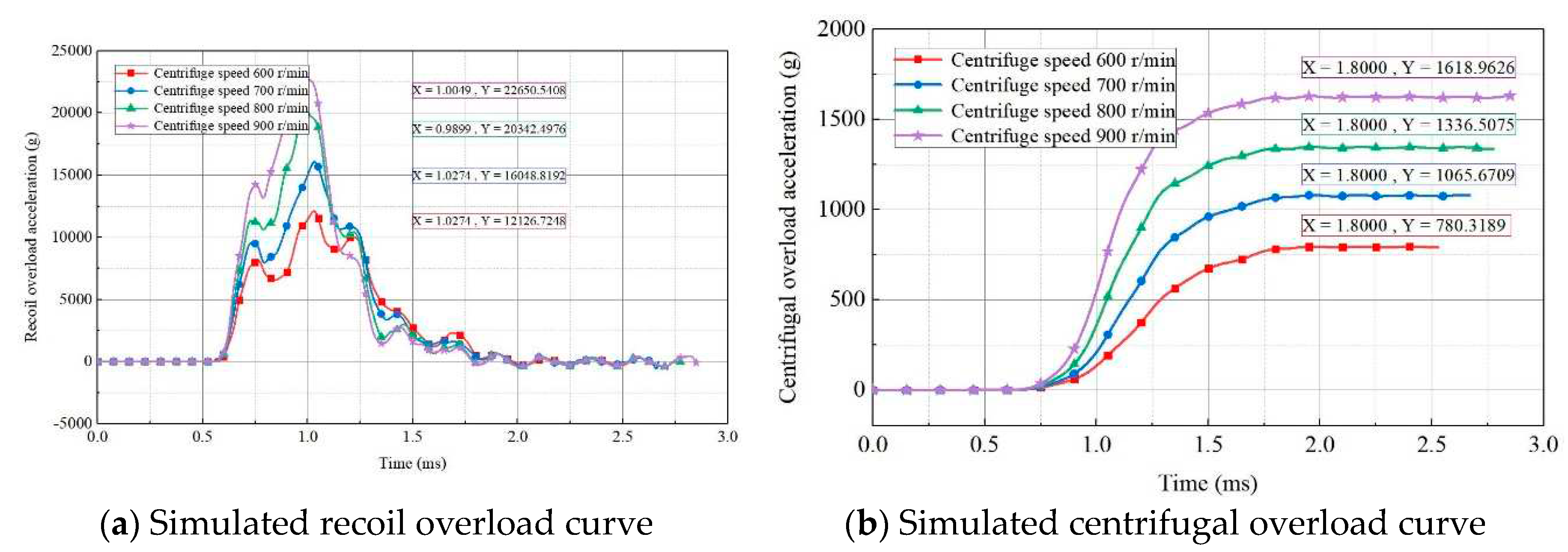
Figure 11.
Simulated 2D overload curves for different cushion materials.
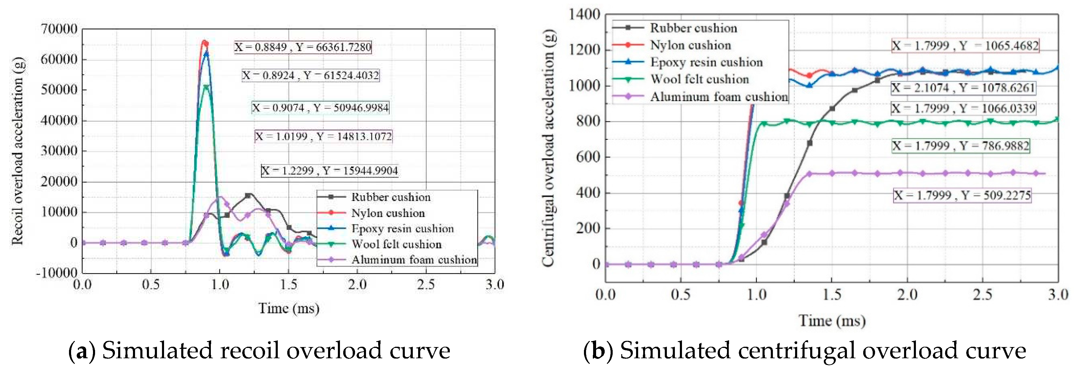
Figure 12.
Simulated 2D overload curves for rubber cushions with different cross-sectional areas.
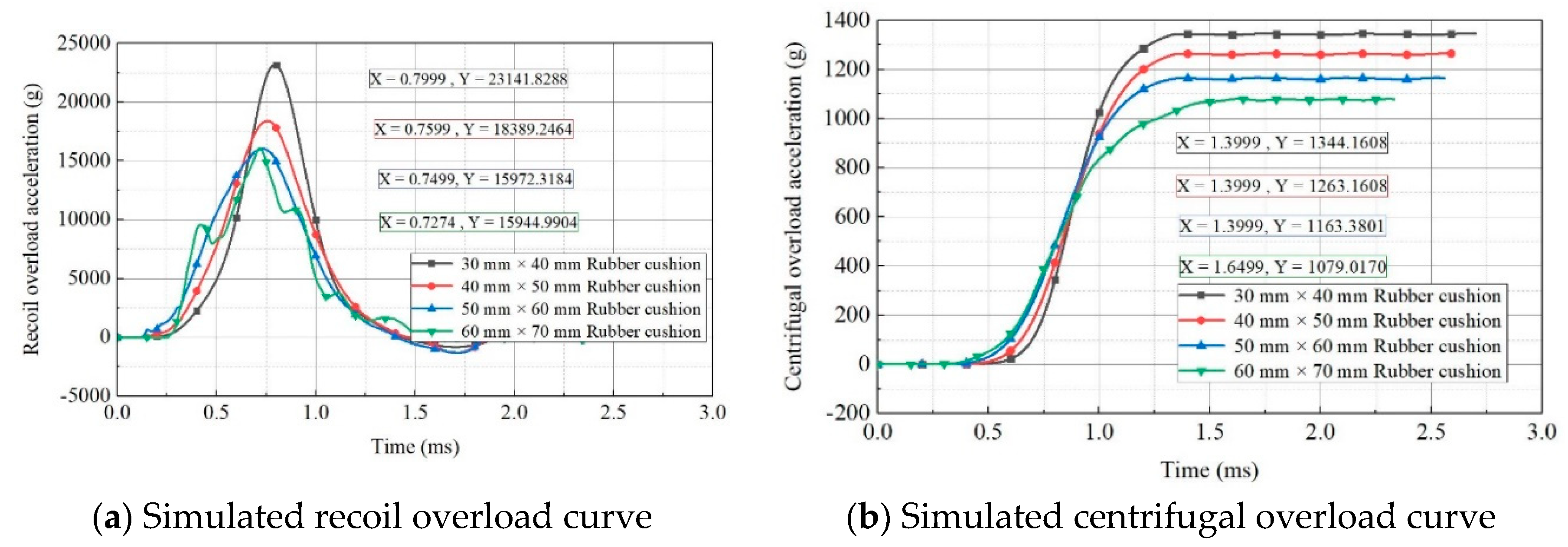
Figure 13.
Simulated 2D overload curves for rubber cushions with different thicknesses.
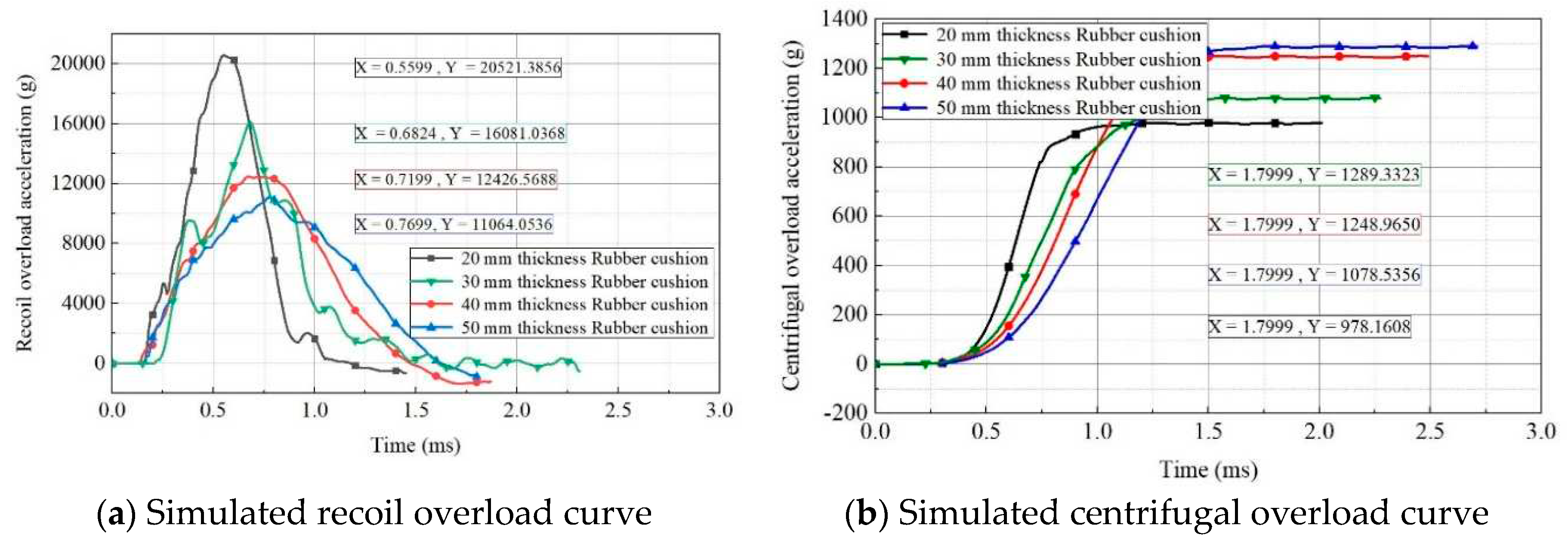
Figure 14.
Simulation test system.
Figure 15.
Block setup.
Figure 16.
Measured curves of recoil and centrifugal overload.
Figure 17.
Measured curves of recoil and centrifugal overload after filtering.
Figure 18.
MEMS S&A device status before and after simulation test.
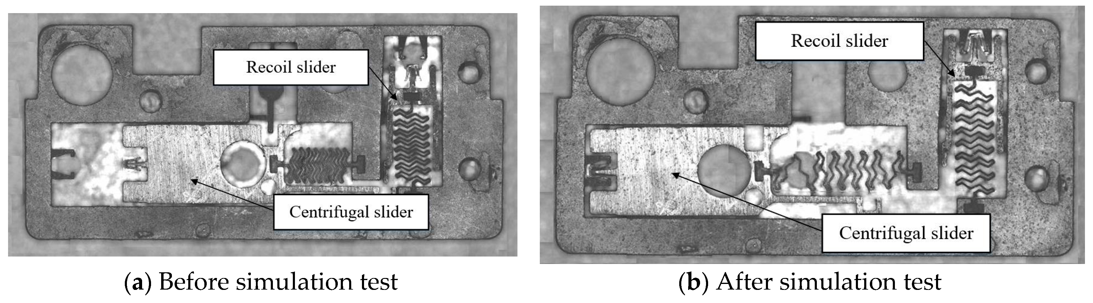
Table 1.
Model parameters of materials in each component.
| Component | Density ρ/(kg·m-3) | Elastic Modulus E/(GPa) | Poisson’s Ratio ν | Yield Limit σs/GPa |
|---|---|---|---|---|
| Impact hammer | 7850 | 210 | 0.28 | 1.28 |
| Block | 2710 | 69 | 0.33 | 0.12 |
| Rubber cushion | 1150 | 1.04 | 0.42 | 0.002 |
Table 2.
Initial velocity of collision at each centrifuge speed.
| No. | Centrifuge Speed / (r/min) | Initial Velocity of Collision / (m/s) |
|---|---|---|
| 1 | 600 | 42.73 |
| 2 | 700 | 49.85 |
| 3 | 800 | 56.97 |
| 4 | 900 | 64.09 |
Table 3.
Models and parameters of different cushion materials.
| Material | Materical Model | Density ρ/(kg·m-3) | Elastic Modulus E/(GPa) | Poisson’s Ratio ν |
|---|---|---|---|---|
| Rubber | MOONEY-RIVLIN_RUBBER | 1150 | 1.04 | 0.49 |
| Nylon | PLASTIC_KINEMATIC | 1100 | 2.80 | 0.40 |
| Wool felt | PLASTIC_KINEMATIC | 1140 | 8.50 | 0.28 |
| Aluminum foam | CRUSHABLE_FOAM | 1100 | 1.20 | 0.33 |
| Epoxy resin | PLASTIC_KINEMATIC | 1150 | 3.20 | 0.40 |
Disclaimer/Publisher’s Note: The statements, opinions and data contained in all publications are solely those of the individual author(s) and contributor(s) and not of MDPI and/or the editor(s). MDPI and/or the editor(s) disclaim responsibility for any injury to people or property resulting from any ideas, methods, instructions or products referred to in the content. |
© 2023 by the authors. Licensee MDPI, Basel, Switzerland. This article is an open access article distributed under the terms and conditions of the Creative Commons Attribution (CC BY) license (http://creativecommons.org/licenses/by/4.0/).
Copyright: This open access article is published under a Creative Commons CC BY 4.0 license, which permit the free download, distribution, and reuse, provided that the author and preprint are cited in any reuse.


