
Submitted:
19 June 2023
Posted:
20 June 2023
You are already at the latest version
Abstract
We propose an experimental method for the unidirectional excitation of spin waves. By structuring Au nanowires arrays within a coplanar waveguide onto a thin yttrium iron garnet (YIG) film, we observe a chiral coupling between the excitation field geometry of the nanowires grating and several well-resolved propagating magnon modes. We report a propagating spin wave spectroscopy study with unprecedented spectral definition, wavelengths down to 130 nm and attenuation lengths well above the 100 μm over the 20 GHz frequency band. The proposed experiment paves the way for future non-reciprocal magnonic devices.
Keywords:
spin waves
; chirality
; non-reciprocity
; spectroscopy
; thin YIG film
1. Introduction
Spin waves, or their quanta magnons carry attractive properties for the development of wave-based computing technologies [1,2,3,4,5], in which the frequency and the phase of the waves can be used as new degrees of freedom for data processing. In particular, their ability to be stirred and shaped in the submicron scale [6,7,8,9] offer great perspectives for the miniaturization of interferometric devices. Furthermore, their integration is compatible with current CMOS [10], and surface acoustic wave nanotechnologies [11]. More significantly, chirality is a strong inherent property of magnetization dynamics [12,13,14,15,16], which puts the field of magnonics in the forefront for the integration of non-reciprocal microwaves components such as isolators or circulators.
Recently, unidirectional transmission of exchange spin waves has been demonstrated by taking advantage of the chiral coupling between the dynamic dipolar field of resonating ferromagnetic nanowires, and high wave-vector spin waves in a thin YIG film [17,18,19]. This technique requires matching the ferromagnetic resonance (FMR) frequency of the ferromagnetic nanowires with the ones of the scanty propagating spin wave modes in the YIG film selected from the excitation geometry. This leads to a non-monotoneous excitation efficiency as each material inevitably have different magnetic properties, and thus different dispersion relations.
In this article, we present an alternative technique for the chiral excitation of exchange spin waves in a 55 nm-thin YIG film using solely the microwave field of an Au nanowires array connected to a coplanar waveguide (CPW). The manuscript is organized as follows: Section 2 presents the design of the Au nanowires grating and the experimental protocol. In Section 3, we show the unidirectional transmission spectra. In Section 4, we present the spectral analysis for all modes with the extracted group velocities and attenuation lengths in the 20 GHz frequency band.
2. Experimental Setup
2.1. Design of the Au nanowire for the chiral excitation
The chiral excitation of spin waves from the microwave field of a nanowire essentially comes from the right-handedness of the magnetization precession at resonance. As sketched in Figure 1a, the phase profile of a propagating spin wave only matches the spatial distribution of the microwave field h of a nanowire for one direction of propagation. Furthermore, the degree of chirality is all the more complete as the field lines are circular, and it will be gradually degraded as the aspect ratio thickness/width of the nanowire () is reduced [20]. This requires fabricating nanowires as thick as wide, which poses some challenge for the nanofabrication.
We designed an array of 40 nm-thick, 100 nm-wide, and 35 nm-long Au nanowires with a a=400 nm lattice constant, and extending over a 6 m (e.g. ≃ 15 wires). The extremities of the nanowires short circuit the signal line and the ground lines of a CPW. In this way, we ensure that the field of each wires are in phase, which improve the definition of the spin wave modes. Figure 1b shows an optical image of the Au nanowires grating sample obtained with a two-steps fabrication process. In a first step, two nanowires array distant of D=20 m are fabricated directly onto a 55 nm-thin liquid phase epitaxial (LPE) YIG film [21] via electron beam lithography, and using an extra layer of conductive resist to circumvent the insulating nature of the substrate [22]. This step is followed by an e-beam evaporation of 40 nm of Au, and lift-off process. In the second step, a 80 nm-thick Au CPW is aligned on top of the Au nanowires using optical lithography.
In order to assess the wave vectors excited from this Au-grating, we consider the in-plane component of the microwave field of the nanowire array as shown in Figure 1c. We used the expression of the Oersted field produced by a single wire with rectangular section [23], and considered a uniform current of 0.01 mA in each wire consistent with the usual values of microwave input power of P=-20 dBm and CPW impedance of R≃30 . We then plot the square of the Fourier transform of this field distribution as shown in Figure 1d, which represents the coupling efficiency in reciprocal space. With such a geometry, we obtain a clear comb of wavevectors that are multiples of the inverse of the grating periodicity, namely . Although the amplitudes of the higher frequency peaks appear to decay rather rapidly, this spin wave antenna geometry provides us with four well-defined, evenly spaced, and workable modes in a broad range of wavevector of [0-50] rad.m.
2.2. Measurement protocol
We performed spin wave spectroscopy measurement on the fabricated sample, which is placed into a home-made electromagnet mounted onto Karl Süss PM-8 microwave probe station. We connect the sample with GGB picoprobes to a vector network analyzer Rohde & Schwarz ZNA-43GHz. Due to the relative small amplitude of spin wave signal, we always proceed to a relative measurement, in which we subtract a reference measurement at a different static magnetic field far enough that it does not interfere in the frequency span with the resonant signal measured at . Finally, as the nanowire array couples inductively to the spin wave, we represent our relative measurements in units of inductance [24,25]:
where the subscripts () denote either a transmission measurement from ports b to port a, or a reflection measurement done on the same port if a=b.
3. Unidirectional excitation of spin waves
Figure 2a shows a () mapping of the reflection spectra acquired between -192 mT to 192 mT. We detect four well-separated branches corresponding to some of the various excited spin wave wavevectors to be identified, the lowest of which corresponds to the FMR mode. A fit of the branch using the Kittel relation [26] gives us a gyromagnetic ratio =28.2±0.2 GHz.T, and an effective magnetization =183± 3mT, in good agreement with previous characterization on similar films [19], and suggesting no in-plane anisotropy.
We show in Figure 2b,c the () mapping of the transmission spectra and measured at -10 dBm input power, and for which we purposely saturated the color scale in order to reveal most of the detectable propagating modes. We also show in Figure 2d–i a zoom of the spectra at 65 mT for the six detected peaks measured at different power to boost the signal-to-noise ratio while insuring a linear response regime. The spectra of Figure 2d,e were measured at -20 dBm, the spectrum of Figure 2f at 0 dBm, and the ones of Figure 2g–i at +10 dBm. They reveal clear features of typical propagating spin wave measurement [7,19,25,27], namely oscillatory signal whose envelope reproduces the spectral signature of Figure 1d.
On one hand, we observe a partial non-reciprocal transmission for the first and the fifth observed branches (Figure 2h). This partial chirality would most likely be improved with thicker nanowires; the current aspect ratio being less than 0.5 in our sample. On the other hand, the transmission for all the others branches is perfectly unidirectional. Furthermore, the non-reciprocity is reversed upon switching the polarity of the applied static field, namely for positive field values, the transmission occurs from port 2 to port 1, and conversely, the spin waves only propagates from port 1 to port 2 for negative fields.
Besides, we also observe that the relative amplitudes of the first four resonance peaks agree relatively well with the spectral definition given by the Fourier transform of this microwave field distribution. Lastly, the period of oscillation of the spectra increases gradually between the second and the fourth peak, which appears to be the largest of all. The fifth peak appears to have the smallest period of oscillation, which suggests it is a higher order perpendicular standing spin wave mode (PSSW).
4. Modal Analysis of the propagating spin waves
4.1. Wave-vector identification
The remarkable spectral definition offered by this technique makes it a technique of choice for broadband spin-wave spectroscopy characterization. In order to identify and analyze the propagation properties of all the detected peaks, we track the field dependence of the resonant frequencies, periods of oscillation, and amplitudes for each branches. Firstly, we proceed to a graphical verification of the wave vector for each field values by matching the Kalinikos-Slavin dispersion relations [28] with the peak position, using the magnetic parameters obtained from the FMR, and an exchange constant =3.85 pJ.m, based on prior study [19]:
Where , ,, and the wave vector modulus of the mth-PSSW mode. We represented in Figure 3a the dispersion of both the uniform thickness mode () and the first PSSW () mode at 270 mT, and their intersections with the peak positions to identify the corresponding wavevector. Following this methodology and taking an average for each modes, we assign the first four propagating peaks to the uniform thickness modes (m=0), and the last two to the first PSSW mode (). The obtained values of wavevector, which are summarized in Table 1, come very close to the expected spectral definition. Figure 3b also shows an excellent agreement between the measured field dependence of the resonant frequency with the dispersion relations Equation (2) for all modes. Furthermore, we notice that although the first PSSW mode (n=0, m=1) clearly appears in the reflection spectra (Figure 2a), it is not visible in the transmission spectra. Indeed, the slope of the dispersion relation close to for is zero, implying a null group velocity at low wavevector.
4.2. Group velocity and attenuation length
The oscillatory signature of the transmission spectra is due to the non-purely monochromatic nature of the excitation (e.g. the finite width in the peaks of the Fourier transform Figure 1d), and the gradual dephasing accumulated over the propagation between the excited wavelengths within a single peak. From the period of oscillation , we can estimate the group velocity of the mode according to [7,25], where D=20 m is the propagation distance. We present in Figure 3c the field dependence of this period of oscillation for all wavevectors (). We observe a fast decay of with the field only for , while it remains fairly constant for the other wavevector. We summarize in Figure 3d the wavevector dependence of the obtained group velocities at representative field values across the full measurement range. We obtain an excellent agreement with the calculated group velocities from the derivative of the dispersion relations . We summarized the measured group velocities for all modes in Table 1. Besides, one can see from the shape of that the higher wave-vector () are already in the exchange regime of the spectrum.
Lastly, we assess the field dependence of the attenuation lengths for all peaks. We consider an exponential decay of the spin wave (namely ), for which we opt for the low-wavevector approximation of the attenuation length , where being the Gilbert damping. We plot in Figure 3e the evolution of the logarithm of each peak amplitudes versus a normalized frequency ). We obtain clear linear dependence, from which we extract an effective Gilbert damping constant for each wave-vector, that we summarized in Table 1. While we obtain similar values with the tabulated Gilbert damping in high quality thin LPE YIG obtained from FMR measurement [21], we seem to observe a slight reduction of the effective damping constant with the wavevector for the uniform thickness mode . Besides, the two branches of the PSSW () mode display slightly higher damping constant. Finally, we plot in Figure 3d the field dependence of the obtained attenuation length for all modes, and verify a good agreement with the low-wavevector approximation across the full field range. We note that the higher wave-vector has an attenuation length well above 100 m up to 500 mT, suggesting possible propagation over macroscopic distances.
5. Conclusions
In conclusion, we showed that a grating of nanowires can excite unidirectional exchange spin waves in an extended in-plane magnetized thin YIG film. We observe a partial chirality at wave-vector lower than 16 rad.m, while it is perfect for higher wavevectors. We expect that the partial non-reciprocity at lower wave-vector would be improved with thicker nanowires. The proposed technique provides an unprecedented spectral definition with evenly spaced and well-resolved spin wave modes up to 50 rad.m ranging over a 10 GHz bandwidth. The comb of wave-vector could even be broaden up to 100 rad.m by reducing the nanowires periodicity by a factor 2. Therefore, this constitutes a method of choice for broadband high wave-vector spin wave spectroscopy studies. In essence, this technique can be applied to any orientation of external magnetic field, and the spectral distribution could be engineered with the gratings dimension to adjust the multi-mode bandwidth operation. Our findings have important implications for the development of non-reciprocal magnonic devices.
Author Contributions
Conceptualization, V.V., L.T., and M.B.; sample fabrication, L.T., J.S., R.B., H.M.; methodology, V.V., L.T.; validation, V.V., L.T., M.B., and Y.H.; formal analysis, L.T., V.V.; investigation, V.V., L.T., G.P.; resources, V.V.; data curation, L.T.; writing—original L.T., V.V.; writing—review and editing, L.T., V.V., V.C., Y.H., and M.B.; visualization, L.T., V.V.; supervision, V.V.; project administration, V.V.; funding acquisition, V.V.; T.R., M.L., and C.D. provided the YIG film. All authors have read and agreed to the published version of the manuscript.
Funding
The authors acknowledge the financial support from the French National research agency (ANR) under the project MagFunc, the Region Bretagne with the CPER-Hypermag project, and the Département du Finistère through the project SOSMAG. M.L. was funded by the German Bundesministerium für Wirtschaft und Energie (BMWi) under Grant No. 49MF180119
Data Availability Statement
The data that support the findings of this study are available from the corresponding author upon reasonable request.
Acknowledgments
We want to acknowledge support from Bernard Abiven for the elaboration of the electromagnet. C.D. thanks O. Surzhenko for magnetic characterisation and R. Meyer for technical assistance.
Abbreviations
The following abbreviations are used in this manuscript:
| YIG | Yttrium Iron Garnet |
| CMOS | Complementary metal-oxide-semiconductor |
| FMR | Feromagnetic resonance |
| LPE | Liquid Phase Epitaxy |
| CPW | Coplanar Waveguide |
References
- Chumak, A. V.; Kabos, P.; Wu, M.; Abert, C.; Adelmann, C.; Adeyeye, A.; Akerman, J.; et al. Advances in Magnetics Roadmap on Spin-Wave Computing. IEEE Transactions on Magnetics 2022, 58, 1–72. [Google Scholar] [CrossRef]
- Barman, A.; Gubbiotti, G.; Ladak, S.; Adeyeye, A. O.; Krawczyk, M.; Gräfe, J.; et al. The 2021 Magnonics Roadmap. Journal of Physics: Condensed Matter 2021, 33, 413001. [Google Scholar] [CrossRef]
- Pirro, P.; Vasyuchka, V. I.; Serga, A. A.; Hillebrands, B. "Advances in coherent magnonics". Nature Reviews Materials 2021, 6, 1114–1135. [Google Scholar] [CrossRef]
- Chumak, A. V. Fundamentals of Magnon-Based Computing. arXiv 2019, arXiv:1901.08934 2019. [Google Scholar]
- Papp, Á.; Porod, W.; Csaba, G. "Nanoscale neural network using non-linear spin-wave". Nature Comm. 2021, 12, 6422. [Google Scholar] [CrossRef] [PubMed]
- Stigloher, J.; Decker, M.; Körner, H. S.; Tanabe, K.; Moriyama, T.; Taniguchi, T.; Hata, H.; Madami, M.; Gubbiotti, G.; Kobayashi, K.; Ono, T.; Back, C. H. "Snell’s Law for Spin Waves" Phys. Rev. Lett. 2016, 117, 037204. [Google Scholar] [CrossRef]
- Loayza, N.; Jungfleisch, M. B.; Hoffmann, A.; Bailleul, M.; Vlaminck, V. "Fresnel Diffraction of Spin Waves" Phys. Rev. B 2018, 98, 144430. [Google Scholar] [CrossRef]
- Gräfe, J.; Decker, M.; Keskinbora, K.; Noske, M.; Gawronski, P.; Stoll, H.; Back, C.H.; Goering, E. J.; Schütz, G. "Direct observation of spin-wave focusing by a Fresnel lens" Phys. Rev. B 2020, 102, 024420. [Google Scholar] [CrossRef]
- Vlaminck, V.; Temdie, L.; Castel, V.; Jungfleisch, M. B.; Stoeffler, D.; Henry, Y.; Bailleul, M. "Spin wave diffraction model for perpendicularly magnetized films" Journ. of Appl. Phys. 2023, 133, 053903. [Google Scholar] [CrossRef]
- Zografos, O.; Sorée, B.; Vaysset, A.; Cosemans, S.; Amaru, L.; Gaillardon, P.-E.; et al. "Design and benchmarking of hybrid cmos-spin wave device circuits compared to 10nm cmos". 15th International Conference on Nanotechnology (IEEE-NANO); IEEE, 2015; pp. 686–689. [Google Scholar]
- Weiler, M.; Dreher, L.; Heeg, C.; Huebl, H.; Gross, R.; Brandt, M. S.; Gönnenwein, S. T. “Elastically driven ferromagnetic resonance in nickel thin films” Phys. Rev. Lett. 2011, 106, 117601. [Google Scholar] [CrossRef]
- Gladii, O.; Haidar, M.; Henry, Y.; Kostylev, M.; Bailleul, M. "Frequency nonreciprocity of surface spin wave in permalloy" Phys. Rev. B 2016, 93, 054430. [Google Scholar]
- Grassi, M.; Geilen, M.; Louis, D.; Mohseni, M.; Brächer, T.; Hehn, M.; Stoeffler, D.; Bailleul, M.; Pirro, P.; Henry, Y. "Slow-Wave-Based Nanomagnonic Diode" Phys. Rev. Appl. 2020, 14, 024047. [Google Scholar]
- Moon, J.-H.; Seo, S.-M.; Lee, K.-J.; Kim, K.-W.; Ryu, J.; Lee, H.-W.; McMichael, R.D.; Stiles, M. D. "Spin-wave propagation in the presence of interfacial Dzyaloshinskii-Moriya interaction" Phys. Rev. B 2013, 88, 184404. [Google Scholar] [CrossRef]
- Di, K.; Zhang, V. L.; Lim, H. S.; Ng, S. C.; Kuo, M. H.; Yu, J.; Yoon, J.; Qiu, X.; Yang, H. "Direct Observation of the Dzyaloshinskii-Moriya Interaction in a Pt/Co/Ni Film" Phys. Rev. Lett. 2015, 114, 047201. [Google Scholar] [CrossRef] [PubMed]
- Otalora, J. A.; Yan, M.; Schultheiss, H.; Hertel, R.; Kakay, A. "Curvature-Induced Asymmetric Spin-Wave Dispersion" Phys. Rev. Lett. 2016, 117, 227203. [Google Scholar] [CrossRef] [PubMed]
- Chen, J.; Yu, T.; Liu, C.; Liu, T.; Madami, M.; Shen, K.; Zhang, J.; Tu, S.; Alam, M. S.; Xia, K.; Wu, M.; Gubbiotti, G.; Blanter, Y. M.; Bauer, G. E. W.; Yu, H. "Excitation of unidirectional exchange spin waves by a nanoscale magnetic grating" Phys. Rev. B 2019, 100, 104427. [Google Scholar] [CrossRef]
- Wang, H.; Chen, J.; Yu, T.; Liu, C.; Guo, C.; Liu, S.; Shen, K.; Jia, H.; Liu, T.; Zhang, J.; Cabero, M. A.; Song, Q.; Tu, S.; Wu, M.; Han, X.; Xia, K.; Yu, D.; Bauer, G. E. W.; Yu, H. "Nonreciprocal coherent coupling of nanomagnets by exchange spin waves". Nano Res. 2021, 14, 2133–2138. [Google Scholar] [CrossRef]
- Temdie, L.; Castel, V.; Dubs, C.; Pradhan, G.; Solano, J.; Majjad, H.; Bernard, R.; Henry, Y.; Bailleul, M.; Vlaminck, V. "High wave vector non-reciprocal spin wave beams". AIP Advances 2023, 13, 025207. [Google Scholar] [CrossRef]
- Yu, T.; Bauer, G. E. W. Chiral Coupling to Magnetodipolar Radiation; Applied Physics Springer book series; Springer Science and Business Media Deutschland GmbH: Germany, 2021; Volume 138, pp. 1–23. [Google Scholar]
- Dubs, C.; Surzhenko, O.; Thomas, R.; Osten, J.; Schneider, T.; Lenz, K.; Grenzer, J.; Hübner, R.; Wendler, E. "Low damping and microstructural perfection of sub-40nm-thin yttrium iron garnet films grown by liquid phase epitaxy" Phys. Rev. Materials 2020, 4, 024416. [Google Scholar]
- Protective Coating AR-PC 5091.02 (Electra 92). Available online: https://www.allresist.com/portfolio-item/protective-coating-ar-pc-5091-02-electra-92/.
- Brächer, T.; Boulle, O.; Gaudin, G.; Pirro, P. "Creation of unidirectional spin-wave emitters by utilizing interfacial Dzyaloshinskii-Moriya interaction" Phys. Rev. B 2017, 95, 064429. [Google Scholar] [CrossRef]
- Bailleul, M.; Olligs, D.; Fermon, C. "Propagating spin wave spectroscopy in a permalloy film: A quantitative analysis" Appl. Phys. Lett. 2003, 83, 972. [Google Scholar]
- Vlaminck, V.; Bailleul, M. "Spin-wave transduction at the submicrometer scale: Experiment and modeling" Phys. Rev. B 2021, 81, 14425. [Google Scholar]
- Kittel, C. Ferromagnetic Resonance. Journal de Physique et le Radium 1951, J9, 291. [Google Scholar] [CrossRef]
- Gladii, O.; Collet, M.; Garcia-Hernandez, K.; Cheng, C.; Xavier, S.; Bortolotti, P.; Cros, V.; Henry, Y.; Kim, J.-V.; Anane, A.; Bailleul, M. "Spin wave amplification using the spin Hall effect in permalloy/platinum bilayers" Appl. Phys. Lett. 2016, 108, 202407. [Google Scholar]
- Kalinikos, B. A.; Slavin, A. N. "Theory of dipole-exchange spin wave spectrum for ferromagnetic films with mixed exchange boundary conditions" J. Phys. C: Solid State Phys. 1986, 19, 7013-–7033. [Google Scholar] [CrossRef]
Figure 1.
(a) Sketch of chiral excitation of SW from an Au nanowire grating. (b) Optical microscope image of the Au nanowire-grating sample. (c) Distribution of the in-plane microwave field. (d) Fourier transform of the in-plane exciting field.
Figure 1.
(a) Sketch of chiral excitation of SW from an Au nanowire grating. (b) Optical microscope image of the Au nanowire-grating sample. (c) Distribution of the in-plane microwave field. (d) Fourier transform of the in-plane exciting field.
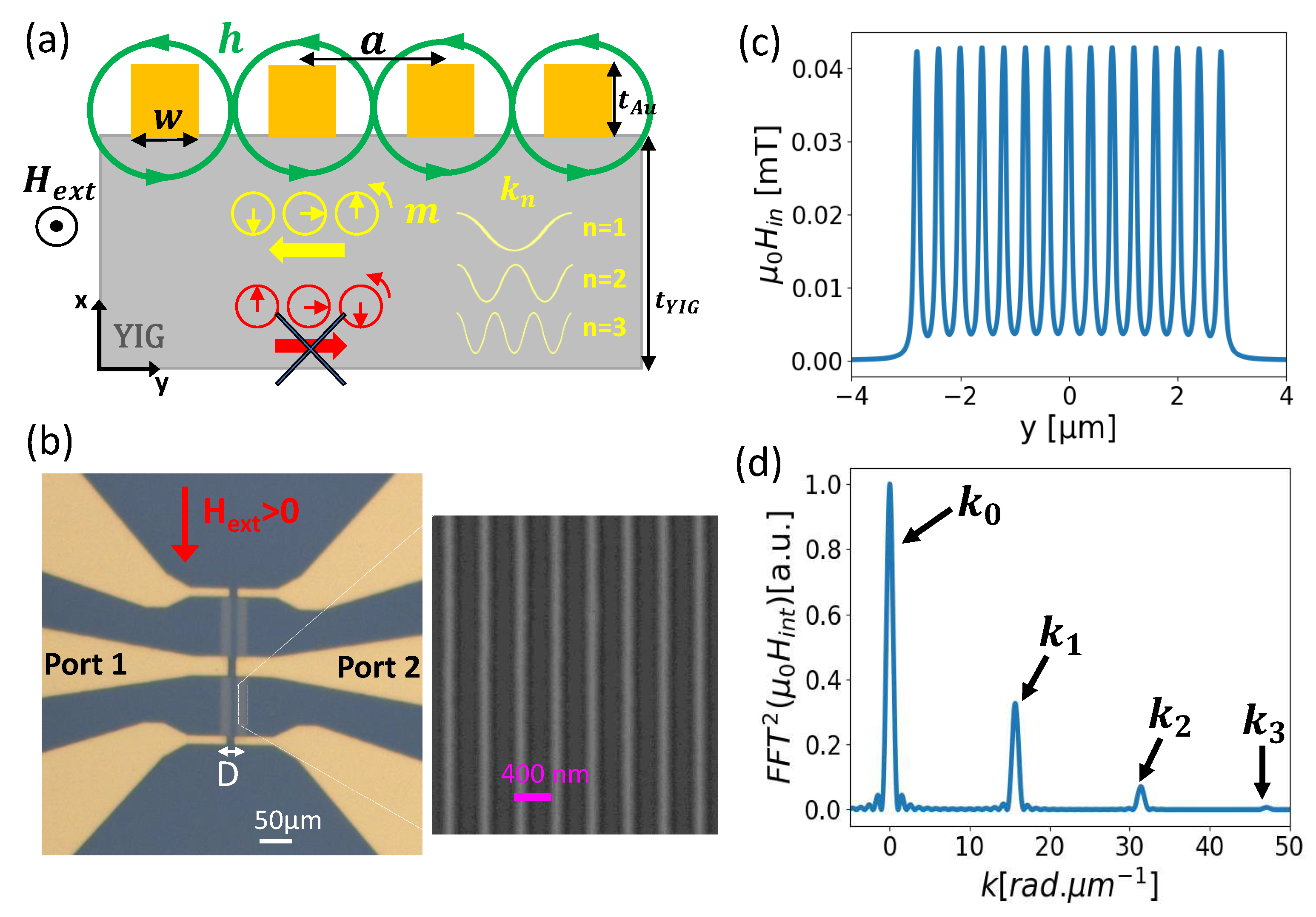
Figure 2.
Mapping () of (a) the reflection spectra, and (b) and (c) the transmission spectra measured from -192 mT to 192 mT. Spectra obtained at +65 mT for (d)-(g) the first four spin wave branches corresponding to the uniform thickness mode , and (h)-(i) the next two branches to the first perpendicular standing spin wave mode (PSSW) Blue (resp. red) lines are (resp. ), and the green lines the .
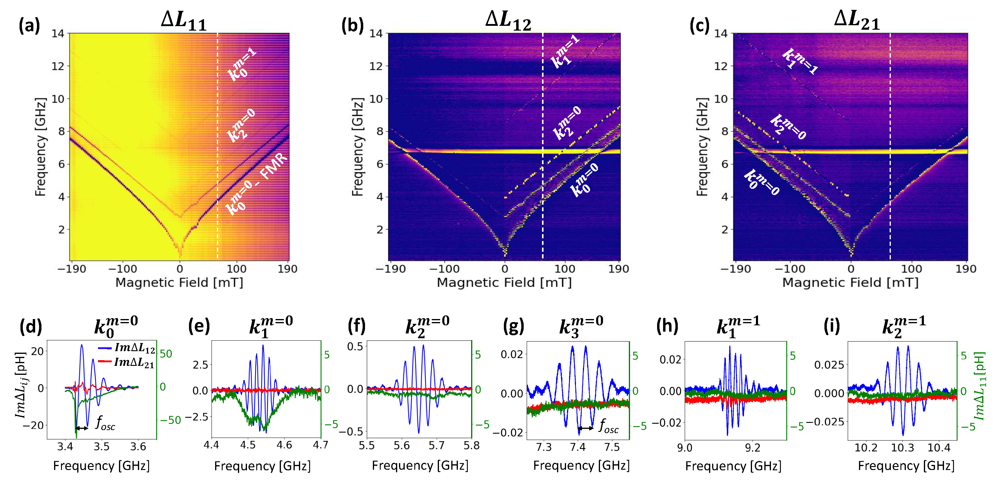
Figure 3.
(a) Dispersion relation for the uniform () and the first PSSW () modes at =270 mT applied field. (b) Field dependence of the resonance frequency for all resonance peaks. (c) Field dependence of the . (d) Comparison of the measured group velocities with theoretical expression at several field. e) Spectra amplitude dependence with the normalized frequency. f) Field dependence of the attenuation length for all wave-vectors.
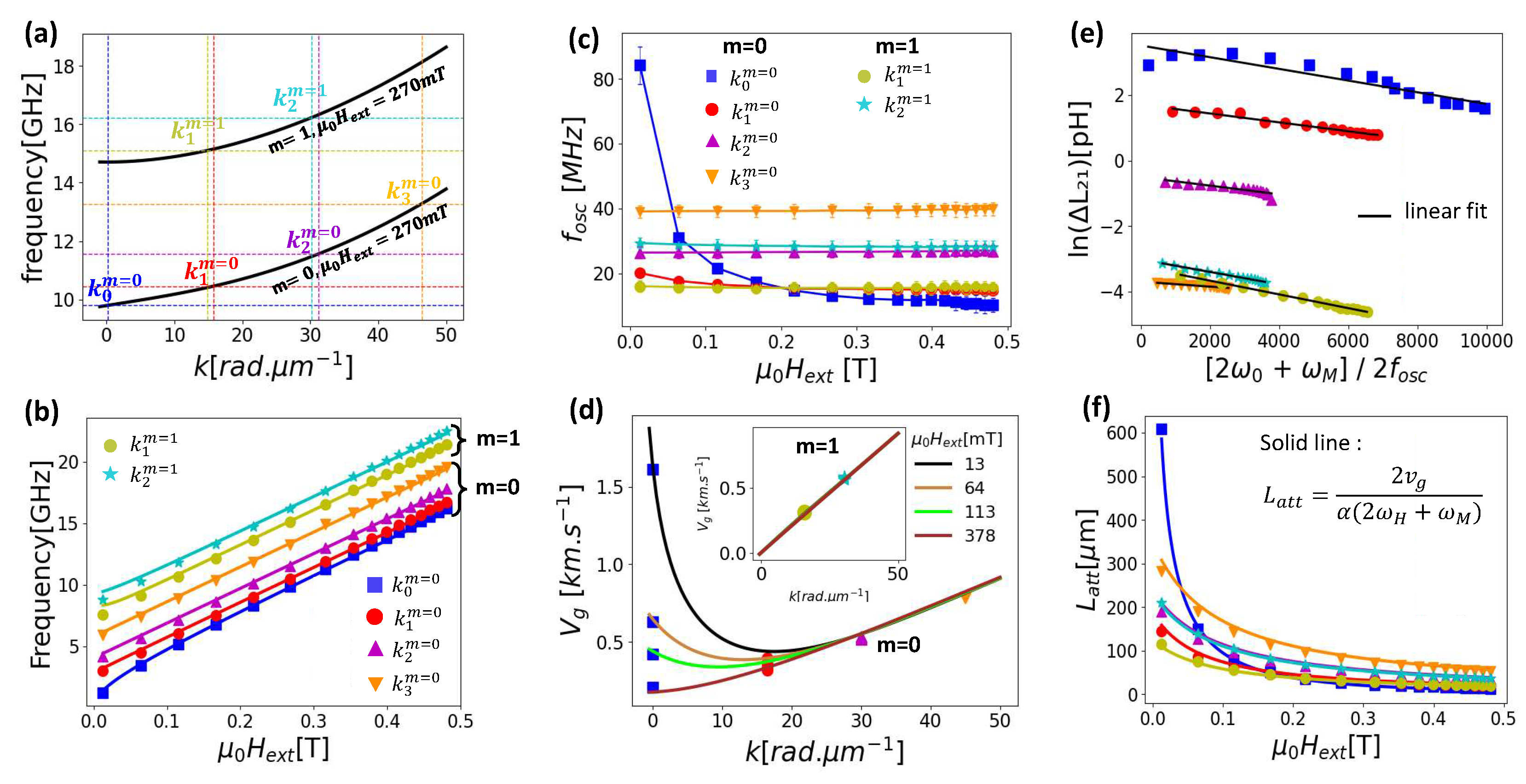

Table 1.
Summary of the modal analysis of the transmission spectra.
| Modes | n | k | ||
|---|---|---|---|---|
| () | [rad.m] | [m.s] | 10 | |
| (0,0) | 0 | 0.03±0.02 | 1614(*) | 1.7±0.1 |
| (1,0) | 15.7 | 16.5±0.5 | 397 | 1.4±0.1 |
| (2,0) | 31.4 | 31.8±0.4 | 535 | 1.3±0.1 |
| (3,0) | 47.1 | 47.0±0.2 | 791 | 0.8±0.1 |
| (1,1) | 15.7 | 15.8±0.8 | 322 | 2.1±0.1 |
| (2,1) | 31.4 | 30.4±0.7 | 587 | 1.9±0.1 |
(*) value obtained at =13 mT
Disclaimer/Publisher’s Note: The statements, opinions and data contained in all publications are solely those of the individual author(s) and contributor(s) and not of MDPI and/or the editor(s). MDPI and/or the editor(s) disclaim responsibility for any injury to people or property resulting from any ideas, methods, instructions or products referred to in the content. |
© 2023 by the authors. Licensee MDPI, Basel, Switzerland. This article is an open access article distributed under the terms and conditions of the Creative Commons Attribution (CC BY) license (http://creativecommons.org/licenses/by/4.0/).
Copyright: This open access article is published under a Creative Commons CC BY 4.0 license, which permit the free download, distribution, and reuse, provided that the author and preprint are cited in any reuse.


