Submitted:
29 May 2023
Posted:
30 May 2023
You are already at the latest version
Abstract
Direct femtosecond laser writing or inscription is a useful technique, and it has been 1
employed to engineer various materials in many applications including nonlinear photonic crystals, 2
which are of periodically patterned second-order nonlinearity to get and control the coherent light at 3
new frequencies. By manipulation of second-order nonlinearity, either erased or poled, quasi-phase 4
matching has been achieved in several crystals, especially three-dimensional nonlinear photonic 5
crystals have been originally proposed and proved to be truly three-dimensional. Here we shortly 6
review on the recent advances in the research field of nonlinear photonic crystals inscribed by 7
femtosecond laser. We also discuss some phenomena that not understood yet and the future possible research topics in this field.
Keywords:
Direct femtosecond laser inscription/writing
; Second-order nonlinearity erasing/poling
; 10 QPM
; NPCs
; SHG
1. Introduction
Frequency conversion processes are employed for generation of new frequencies desired, which has attracted many research interests, due to its existing and potential applications in nonlinear photonics, including new laser sources [1], nonlinear optical microscopies [2], optical communications [3] nonlinear hologram [4], optical tweezers [5,6], and quantum information [7,8]. There are several processes to get nonlinear frequency conversion, including second harmonic generation(SHG), difference-frequency generation (DFG), summer-frequency generation (SFG), optical parametric oscillation (OPO), and optical parametric amplication (OPA) [9]. Among them, SHG is the mostly used for frequency doubling. As early as in 1962, Armstrong and his coworkers revealed that the process of SHG is dominated by the phase mismatch(), which is the difference of the the fundamental wave vector and second harmonic (SH) vector [10]. In most cases due to dispersion of nonlinear crystal, and electromagnetic energy of the propagating laser oscillates between the fundamental wave and the second harmonic wave with an oscillation length . In order to get a SH emission of good quality and high efficiency, the phase mismatch must be eliminated.
There are generally two methods to overcome the dispersion of nonlinear crystal. One way is birefringence phase matching (BPM), which is experimentally demonstrated as early as in 1961 [11]. By choosing proper orthogonal polarizations of the fundamental wave and taking use of optical anisotropy of the nonlinear crystal, the phase-matching condition is fulfilled, i.e. [9]. However, BPM is limited by the small birefrigence of some popular nonlinear crystal including LiNbO, and conversion efficiency is restricted by the so-called walk-off angle [9]. The other way is to periodically pole second-order nonlinearity to get a quasi-phase matching (QPM) [10,12]. In this case, the second-order nonlinearity is spatially modulated, leading to a reciprocal vector lattice (RVL) that contributes to the interacting wave vectors [13]. Consequently, the phase matching condition is modified as: . For example, a simple 1D grating (see Figure 1 (a)) gives , with m is an integer and is the poling period. According to the Fourier transform, when the duty cycle is 0.5, the intensity of the corresponding RVL is . Obviously, the first order RVL, where , has the largest Fourier coefficient.
One traditional and well-developed technique of QPM is to pole ferroelectric domains by electric field in ferroelectric crystals [14,15,16], and the most popular one is periodically poled lithium niobate (PPLN) [17,18]. Other methods including chemical indiffusion [19,20], crystal-growing technique [21], scanning force microscopic poling [22], electron-beam poling [23,24], UV-light poling [25,26] have been developed for specific circumstances. Those QPM techniques can be applied in these nonlinear optical crystals that are not suitable for BPM. In most cases, the largest nonlinear coefficient can be used and the spatial walk-off angle can be avoided with QPM technique. The 1D QPM configuration is extended to 2D and 3D by Berger, and a concept of nonlinear photonic crystal (NPC) is introduced, where the second-order nonlinearity is spatially periodically modulated without changing the refractive index [27]. It is in analogy with photonic crystal (PC) whose refractive index is periodic controlled [28,29], while for the ferroelectric domain poled NPCs, the refractive index is slight changed. Generally the phase matching condition is modified as: , where is the 3D RVL (see Figure 2c). Correspondingly, the 3D RVL is expressed as , with n and l are both integers, and are the poling periods along the and z axes respectively. So the second harmonic emission is versatilely generated [30,31,32] by choosing different combinations of and . Furthermore, NPC is able to shape the wavefront of the second harmonic emission, which is important in nonlinear spatial modulation [33,34].
Going over to 3D, the NPCs expend a plenty of unique applications, such as 3D nonlinear beam shaping [35], high-dimensional entanglement [36,37], and optical communications [38]. However, the electric field poling is always involving a complex fabrication process of electrodes, and the electric field must be applied along the axis of spontaneous polarization, making the electric field poled NPC always a 1D or 2D structure [39,40,41]. Therefore, NPC was restricted to 1D and 2D for a long time, because no technique was able to manipulate in 3D before direct femtosecond laser inscription of technique was developed. It is a material-light interaction either erasing or poling introduced by tightly focused near-infrared femtosecond laser. For the first approach, tightly focused laser beam partially destroys the crystalline structure of the dielectric crystal in the beam focal region, and the strength of the second-order nonlinearity is locally reduced. The second approach is to invert the spontaneous polarization by applying thermoelectric or manipulating pyroelectric field by femtosecond laser itself, or with a post heat-treatment, and a charge source. The domain inversions are catalogued into two types: the primary domain inversion in the focal region due to the thermoelectric field and the secondary domain inversion outside the laser focal region caused by the pyroelectric field. By applying both techniques, one can inscribe 3D patterns of inside the nonlinear crystal as wish. In addition, the direct laser inscription technique has been wide applied for many applications in the field of photonic crystals and on-chip devices [42,43] The extension of this technique to ferroelectric crystals paves the way to achieve monolithic fabrication of 3D nonlinear integrated photonic devices for all-optical communication and on-chip signal processing. In this review, we focus on the all-optical -engineering techniques. We will go over both the -erasing and the -poling techniques, and demonstrate their recent progresses and applications in NPCs, respectively.
2. -erasing technique by femtosecond laser
Femtosecond laser inscription is a popular technique to fabricate structures inside transparent material by engineering its bulk refractive index [44]. The energy of tightly focused pulses is nonlinearly absorbed and confined into the focal volume before free electrons excited by it dissipate to the surrounding area due to the short period of the pulse [45]. The multiphoton absorption [46] localized on a micro- and submicro-scales leads to bond-breaking and re-bonding, constituents migration or thermomechanical effect effects [47,48,49,50,51,52,53,54,55].
Therefore, refractive index is changed [56,57,58], which is applied in many applications such as three-dimensional optical storage [59], surface modification [60], photonic devices [61] and optical fluid [62], especially in the field of waveguide [63,64,65,66,67,68,69]. The modification induced by femtosecond laser results in two types of refractive index changes [48,49,70]. Type I modification is a tiny positive index change, where n is in the range of due to a slight change or the phase transition of the structure. Therefore, the energy required for inscription is relatively low [57]. Type II modification refers to a large refractive index change, for there are voids brought in by micro-explosion induced by high writing energy [71]. Recently, type I modification is developed to engineer the second-order nonlinearity to get a so called laser-induced quasi-phase matching (LiQPM). In this case, instead of being periodically switched, is selectively erased by optimized laser engineering parameters. Generally, is partially destroyed and the residue is marked as d, defining a ratio (), where is the original second-order nonlinearity of the crystal. The second-order nonlinearity is totally destroyed when =0, while it is unchanged when =1. Periodic erasing of also introduces a RVL, which is analogue with the RVL in -poling QPM. For 1D grating pattern with a period of and a duty cycle of 0.5 (see Figure 1(b)), the intensity of the corresponding RVL is . The conversion efficiency of LiQPM is maximized as when , which is half of that in poled ferroelectric domain QPM in Figure 1(a).
Recently, the -erasing technique has attracted a lot of interests since Thomas et al. produced the first 1D grating pattern by LiQPM (see Figure 3 (a)-(c)) in an x-cut LiNbO in 2013 [72]. Employing this structure, a very poor conversion efficiency of is observed. Imbrock et al. demonstrated a 1D grating integrated with cladding waveguides (see Figure 3 (d)-(f)) in a z-cut LiNbO in 2015, which is the first demonstration of integration two types of crystal modifications induced by femtosecond laser [73]. By reducing possible diffraction lost, the conversion efficiency of energy is increased to 5.72%. Besides, they also developed a chirped structure for broadband SHG and a cascaded single-period structure for generating parallel multi-wavelength SHG [74]. In 2018, Wei et al. reported a 3D NPC by selectively erasing in a z-cut Mg-doped LiNbO (see Figure 4), which is the first experimental demonstration of 3D NPC by the -erasing technique [75]. The conversion efficiency is highly increased benefiting from the versatile phase-matching configuration in 3D NPC. They also proposed a nonlinear beam shaping with a 3D NPC (see Figure 5) fabricated by this technique [76]. Zhu et al. extended this technique to engineer on the surface of a BPM crystal and got a high-efficiency nonlinear beam shaping [77], where the phase matching condition is fullfilled through the birefrigence in longitudinal direction and nonlinear Raman-Nath condition in transverse direction (see Figure 6) respectively. Furthermore, they proposed a nonlinear holography in a monolithic lithium niobite crystal [78]. Shao et al. demonstrated 1D QPM in cut quartz as well as in cut LiNbO crystals [79]. Especially, they proposed a generation of deep ultraviolet wave of nm by the quartz sample with a conversion efficiency of . They also demonstrated an angular engineering strategy of a LiQPM structure for widely tunable SHG and experimentally demonstrated it in a quartz crystal [80]. The output wavelenght covers from 221 to 332 nm and the conversion efficiency at the peak power is more than .
3. -poling technique by femtosecond laser
Laser light are employed in ferroelectric domain inversion engineering in two ways: indirectly or directly. In the first approach, the poling of the ferroelectric crystal is prior to the application of an external, homogeneous electric field, enhanced by the laser light to reduce the coercive field [81,82,83]. Therefore, selective uniform illumination of femtosecond laser on ferroelectric crystal by results in spatially selective domain inversion, eliminating the need for structured electrodes or crystal heating during voltage application. Several groups have reported related works with different ferroelectric crystals on this technique [84,85,86,87]. It has been improved as a two-step voltage application under UV light either with the help of a mask [88] or a beam writing technique [89] to realized a 2D domain inversion in MgO-doped LiNbO. Later it is reported that the UV light and the electric field is not necessary to be applied simutaneously [90]. However, the electric field must be applied along the polar axis of the crystal for domain inversion, consequently, the UV-assisted poling technique can never be employed in three dimensional. In the second approach, which was proposed as early as in 1994 [91]. It is suggested that the strong electric field generated by the propagating ultrashort pulses could accelerate ions in the ferroelectric crystal. As a result, the kinetic energy of the ions is increased so that they would be able to switch between their two stable positions, leading to spontaneous polarizations flipped. Not until 2005, it was experimentally demonstrated that short ultraviolet (UV) pulses laser could promote nanoscale domain inversions on surface on LiNbO crystal due to a strong absorption of the UV light [92]. Later, it is discovered that the inversion of ferroelectric domain only happens under a certain intensity of laser light and a concept of domain reversion window is proposed [93]. It is an energy range of continuous laser pulse that can induce domain inversion, which is theoretically and experimentally confirmed [94]. However, there is no systematic study of the inverted structure either in Ref. [93] or in Ref. [94].
Recently, several all-optical domain inversion methods induced by femtosecond laser inscription are approached [95,96,97,98,99], where the mechanisms to invert spontaneous polarization are totally different with the one proposed in Ref. [91]. Basically, ferroelectric domain inversion is caused by femtosecond laser with pulse energy under the danmage threshold, i. e. there is no structure modification induced in the domain inversion region under investigation. Either the thermoelectric field [100] or the pyroelectric field [102] induced by a femtosecond laser or a thermal annealing is the direct reason to flip the spontaneous polarization. Therefore, the poling mechanisms are categorized into two sorts: the primary domain inversion due to the thermoelectric field and the secondary domain inversion because of the pyroelectric field. As long as the employed femtosecond laser meets some certain requirements, is inverted instead of erased at arbitrary place and along any orientation, without damaging the crystalline. Consequently, is modified in such a way that there is no scattering loss, thus the conversion efficiency is significantly increased for this type of QPM compared with that via LiQPM.
3.1. The primary domain inversion:
Multi-photon absorption of the laser beam at the focal point leads to the local temperature being increased rapidly [103,104]. Consequently, the temperature gradient between the laser focal region and the surrounding area results a 3D thermoelectric field. Taking LiNbO as an example, only the z component of this electric field is related with the domain inversion ( see Figure 7) [96,105], which is bipolar in the focal region: one half is anti-parallel to the spontaneous polarization, while the other half is parallel to the spontaneous polarization. Besides, ionic conductivity is increased by laser heating, leading to a local reduction of the coercive field to make it easier to invert the spontaneous polarization at the laser focal point [106]. When thermoelectric field surpasses coercive field, domain inversion happens in half of the focal volume, where the thermoelectric field opposes direction of spontaneous polarization. In this model, pyroelectric field is ignored within the laser focal region, for it is one order smaller compared with the thermoelectric field [98]. Normally, inverted domains have an elongated form due to spherical aberration induced by refractive index difference when laser beam enters crystal from air [95]. The laser intensity decays along the propagating direction for the absorption of it is intensity-dependent. Meanwhile, the laser goes through a birefringence that introduces multi focus [107,108]. Therefore, the inverted domain has a larger cross-section in the incoming direction of the laser than that in the outgoing direction [96].
The model of the primary domain inversion described above is first proposed by Sheng et al. and they have reported a series of work based on this model [95,96,105]. Starting dealing with LiNbO, they demonstrated a 2D QPM structure with an engineering accuracy of about m [95], then integrated this structure with a waveguide, leading to a conversion efficiency of 17.45% for doubling a fundamental wavelength of 815 nm [96]. In the contrast, the highest conversion efficiency via LiQPM reported is 5.72% [73]. Furthermore, they applied this technique to invert ferroelectric domains in a tetragonal perovskite ferroelectric crystal of barium calcium titanate (BCT) and captured a -like domain structure directly introduced by the 3D thermoelectric field (see Figure 7). It is clear that there is a central horizontal line representing the domain wall and perpendicular to the spontaneous polarization of the BCT. Furthermore, they demonstrated a 3D photonic crystal of simple tetragon fabricated by this technique and got two types of SHG via it: a square lattice of SH spots located at the center which is a standard nonlinear Raman-Nath diffraction [30], and peripheral spots distributed as homocentric rings situated relatively far from the center which is the direct evidence of the 3D characteristic of the nonlinear interaction.
Later, they go on this topic and demonstrated several works in applications of nonlinear beam shaping, employing calcium barium niobate (CBN) crystals. Firstly, they demonstrated an experiment of nonlinear wavefront shaping through a 3D NPC [109]. In this report, a 3D nonlinear structure of three layers including fork, linear and circular grating is proposed and employed for parallel 3D nonlinear wave shaping. Those three patterns are transversely overlapped inside a CBN crystal, and converted a fundamental Gaussian beam into three pairs of second harmonic vortex, Gaussian, and conical beams simultaneously. In addition, the 3D nonlinear wavefront shaping is dynamically controlled for the first time by adjusting the distance between two adjacent patterns. Secondly, they promoted a curved fork pattern (see Figure 8) to approach a perfect vortex second harmonic, of which the diameter is insensitive to the topological charge [110]. This is the first demonstration of a perfect vortices by the nonlinear beam shaping method, while which has been realized in linear optics [111,112]. Thirdly, they approached a real 3D nonlinear volume hologram of high quality [113], that a vortex second harmonic zero zero intensity in the center was generated effectively at the resonance frequency. Fourthly, they also demonstrated 2D and 3D NPCs of hexagonal patterns in a single ferroelectric domain CBN crystals [114]. In this work, multi-ferroelectric domain CBNs were made into single-ferroelectric domain crystals before patterns are inscribed in them. Subsequently, those samples were used in SHG experiment via the nonlinear Raman-Nath diffraction and got similar SHG pattern as shown in Ref. [105]. The generated second harmonic emission possesses a hexagonal symmetry, with its intensity increasing monotonically along the propagation. Comparing those SH emissions via the 3D NPC and via the 2D NPC, the one generated by 3D PNC is much higher as expected. In addition, the 2D NPC pattern is also carried out in a multi domain CBN crystal, and the SH emission via the single domain sample is higher. The poled domains appear to be stable and can be completely erased by thermal annealing above Curie temperature for 30 mins, as well as the single-ferroelectric domain.
A second model of primary domain inversion is proposed by Xu et al. [98]. They demonstrated a nonreciprocal femtosecond laser-writing technique in LiNbO with a resolution of 30 nm, where the 3D domain inversion is rewritable. To be noticed, a prefabricated drain is required in this model to effectively guide the electric charges produced during the poling process, without which the laser inscription of the same parameters can never produce an inversion of domain. This engineering process is properly simulated, assuming that the input laser has an intensity of Gaussian profile. Thus, it could be expressed as: , where is a constant current and is a 3D Gaussian function. Since LiNbO crystal has a strong absorption at 318 nm and the wavelength of the femtosecond laser utilized here is 800 nm, the nonlinear absorption is a three-photon process [103,104]. Thus, the generated heat is:
with is the three-photon absorption coefficient of LiNbO. Now, a solid heat transfer model is considered as follow:
where is the density, is the heat capacity, is the thermal conductivity of LiNbO crystal, respectively. T is the temperature and is the velocity vector. Supposing S is the Seebeck coefficient, the temperature gradient between the hot laser focal point and the cold surrounding area induces an electric field:
The simulated 3D thermoelectric field is shown in Figure 9(a), and the z components of it is presented in Figure 9(c), with parallel and antiparallel to the spontaneous polarization. Within the enclosed ellipsoidal area denoted by a and b, the thermoelectric field excesses and flips the spontaneous polarization when antiparallel with it. For example, in Figure 9(c) only flips the local spontaneous polarization. Therefore, this poling technique strongly depends on the laser-writing direction and is rewritable. As shown in Figure 9 (d), the laser both comes and writes along the direction which is also the spontaneous polarization direction. Figure 9(d) and (g) indicate that when the laser beam moves along the direction, switches the polarization back no matter what direction it was. If it was flipped, the laser acts as an eraser; if it was normal, the laser does not work at all. In the contrast, when the laser moves along the direction, overtakes and the domain is inverted (see Figure 9(e)) with a width of a. In another case, as shown in Figure 9(f), the laser moves along the y axis of the crystal and half of the laser focal area is inverted by with a width of b. Therefore, with a proper design, the focused laser beam can be used as a laser pen or eraser to fabricate arbitrary 3D ferroelectric domain structures.
A third model owning the same principle with the primary domain inversion is performed by Wang et al. [99]. It is a two-step poling technique: the first step, laser marking, is to create a tiny seed by a single pulse illuminated along the z-axis either on the surface or inside the LiNbO crystal, shorted for LM; the second step, laser inducing, is to induce a temperature gradient by moving the focal point of the multiple laser pulses away from the seed, shorted for LI. This high temperature gradient induces a 3D thermoelectric field, which not only makes the domain inverted but also drives the inverted domain growth when it surpasses the coercive field. LMs which are type II modification can be inscribed not only on the surface but also inside the crystal, requiring different pulse energy for the slight loss during propagation Generally, the seeds have uncontrollable random quality. Therefore, oversized or downsized seeds will make it harder to pole the ferroelectric domains, unfortunately the mechanism of which is not understood yet. Furthermore, because the coercive field varies at each point of the crystal, correspondingly the minimum energy of the multiple laser pulses for inducing the poling varies from 600 nJ to 700 nJ. It must be mentioned that a single LI can invert ferroelectric domains along thousands seeds within a region about 200 m simutaneously, thus this method is highly efficient and energy-saving.
3.2. The secondary domain inversion
The model of secondary domain inversion is also a two-step process: laser inscription and a follow-up heat annealing, which is similar with the one demonstrated in [99]. Laser-induce filaments act as seeds to induce domain inversion in a subsequent thermal treatment, which is first demonstrated by Imbrock et al. [97].
Pyroelectric field instead of thermoelectric field plays an important role here. More specifically, the sum of depolarizating field due to the spontaneous polarization, screening field and thermally activated bulk charges are taken into account to explain the mechanism of domain inversion. In some certain ferroelectric crystals such as LiNbO, domain back switching and domain wall motion can be promoted by a temperature change. The heating or cooling will change the magnitude of spontaneous polarization temporarily, therefore is temperature-dependent. Normally, the pyroelectric field can be expressed as:
At room temperature, is fully screened by bulk and surface charges, thus, (see Figure 10(a)). When the crystal is being heated, the polarization is decreasing, leading to a reduction of . Therefore, is not zero any more and the net value is parallel with (see Figure 10(b)), which can be expressed as:
with is the temperature change, p is the pyroelectric coefficient. Meanwhile, the thermal heating will activate charges to drift into the pyroelectric field, resulting a new field of charges parallel with to compensate (see Figure 10(c)). Now the pyroelectric field is zero again and expressed as:
The concentration of the charges is higher inside the filament than that in the unexposed area, which leads to a larger charge field and a larger domain inside the filament [115]. Subsequently, the spontaneous polarization increases and the enlarges as well in the process of cooling down, resulting in the pyroelectric field antiparallel to (see Figure 10(d)). When the value of this pyroelectric field in the exposed area is larger than the threshold electric field, the spontaneous polarization is inverted.
This technique is suitable for those ferroelectric crystals with high pyroelectric coefficients, and one of them is LiNbO with a dielectric as large as 28 and a pyroelectric coefficient C/(mK) [116]. A unidirectional domain inversion along z-axis of MgO-doped lithium niobate crystal is proposed in Ref. [97] (see Figure 11). Filaments locate either on surface or in the middle of z axis, and the corresponding domain inversions are extended either to the other surface or to both sides. The width of the domain inversion depends on the fluence of the femtosecond laser and the length of the filament. Moreover, the domain can have a high aspect ratio of length/width up to 800 m/1 m with all domain boundaries being straight over the entire domain length. Further more, the effect of temperature during the heating treatment and the lattices periods on the number and size of inverted domains are investigated in a 2D NPC [115]. A threshold temperature is identified as C, and an optimal temperature regime is C - C, within which all domains can be inverted in a 2D rectangular lattice with periods of 15 m × 6.3 m. Above C, the already inverted domain switch back. Smaller lattice periods and lower temperatures result in fewer inverted domains, while the average of the central domains is 2.38 m, which almost independent of the temperature and lattice periods. In addition, the normalized effective nonlinear coefficients of 2D NPC under study is calculated on the order of 1%. This limitation is due to the small duty cycle restricted by this method.
3.3. Two types of domain inversion showing up simultaneously
The PT-relaxor ferroelectrics not only exhibit excellent piezoelectric but also own large second-order nonlinearity, therefore they are good candidates for NPCs. One of them is single-domain crystal of 0.62Pb(MgNb)O-0.38PbTiO (PMN-38PT), which has a coercive field of 8.25 kV cm [117]. However, the coercive field for the intrinsic LiNbO crystal is about 5420 kV cm and for the congruent LiNbO crystal is 210 kV cm [118,119]. Therefore, the domain inversion is relatively easier to be attained in PMN-38PT crystal compared with LiNbO. Recently, primary and secondary domain inversions are simultaneously demonstrated in PMN-38PT crystal by Sheng et al. [120]. The nonlinear absorption of femtosecond laser not only leads to a thermoelectric field inducing a primary domain inversion at the focal region, but also generates free carriers inside it leading to a secondary domain inversion around it (see Figure 12(c)), depending on the laser beam power. Here, the secondary domain inversion is based on the same mechanism as proposed in Ref. [97] that demonstrated in the previous subsection. However, there are two significant differences: it has a shape of hollow cylindrical structure (see Figure 12) and grows only on one side of the focus. It is because that the redistribution of the free carriers results in a cylindrically symmetric space charge field, the pyroelectric field is unidirectional outside the focal region while the thermoelectric field is bipolar inside the laser focal region. Furthermore, the laser has an effect of erasure on the secondary domain inversion, for the thermoelectric field switches back the flipped spontaneous polarization induced by pyroelectric field in the overlapping area when the interval distance between two patterns is small enough, the mechanism of which is similar as demonstrated in Ref. [98]. Sheng et al. also performed a 1D QPM structure and firstly demonstrated a quasi-phase matched collinear SHG in PMN-38PT crystal [121]. Three different processes of nonlinear interaction are observed by controlling the linear polarization of the fundamental beam. Furthermore, the relative strength of all second-order nonlinearity tensor elements are determined by comparing the emission power of the SHG at QPM resonances, and the absolute value of the is computed as 1.3 pm/V, which is the first quantitative measurement of nonlinear properties of a PMN-38PT crystal.
4. Laser writing parameters
Either for -erasing or -poling technique, the later-writing parameters including pulse energy and scanning speed is highly depend on the properties of the applied crystals and the specific structure. Generally, mode-locked Ti:Sapphire femtosecond laser systems with regenerative amplifiers are employed as light sources for their stabilities. Typically, the centered wavelength is 800 nm, the FWHM ranges from 75 fs to 180 fs [95,97,98], and the applied pulse energy of laser is significantly dependent on the application purpose of the laser beam. More specifically, for LIQPM low repeat frequency of 1 kHz with scan speeds varying from 50 to 100 m/s are used for small structures with a cross-section of several tens micrometers diameter [73,75]. Pulse energy here varies from 100 nJ to 200 nJ depending on the depth and specific crystal. Mediate repeat frequencies of hundred kilohertzs with scan speed of 1 mm/s are used for large scale patterns with a cross-section of several hundreds micrometers diameter, where single pulse energy is as large as 650 nJ [72]. Besides, compact ytterbium-doped diode-pumped ultrafast amplified lasers are also employed as light sources, for example a laser with a FWHM as large as 500 fs and a wavelength of 1030 nm is used to erase [77]. In this report, the repeat frequency is 1 kHz with a scan speed of 280 m/s, and the single pulse energy is 900 nJ.
The pulse energy for -poling is smaller compared with the energy used in LIQPM, because that the crystal structure must not be destroyed for -poling. For example, the repeat frequency employed is around 76 MHz and the corresponding pulse energy is no larger than 5 nJ, which is optimized by the depth [95]. Generally, the scan velocity is as slow as 10 m/s that is time-consuming. Specially, in the two-step primary domain inversion technique, one single pulse with energy of 150 nJ is utilized to generate a mark of type II modification, and the repeat frequency of 500 kHz with pulse energies from 400 to 900 nJ is applied for the generation of thermoelectric field [99]. In contrast, for the two-step secondary domain inversion, type II filaments are induced by a repetition rate of 1 kHz with energies from 50 to 550 nJ [97]. Some typically detailed inscription parameters are listed in Table 1.
5. Conclusion
Direct femtosecond laser writing on second-order nonlinearity has enormous potential for its unique 3D microfabrication ability is unreplaceable by other methods. It has been showing great advantages and will play a significant role in the field of nonlinear photonics, providing a promising technique for versatile integrated optical applications. Recent advances and achievements in this research field are briefly overviewed, nevertheless, there are some challenges to be further investigated. Firstly, the mechanism of refractive index modification induced by femtosecond lasers is not entirely understood, which greatly depends on the employed femtosecond laser system parameters and the properties of crystals. For example, the trace on fused silica induced by one single pulse short of 1 m with a bandwidth of 150 fs focused by objective of an effective numerical aperture 0.4 contributed both negative refractive and positive index changes, in the contrast, there is no sign of type II modification when focused with an effective numerical aperture 0.3 even with 5000 pulses [70]. Until now, the mechanism is somehow still a mystery, and further investigation of the effect of each parameters is required. Secondly, the mechanism on femtosecond laser induced poling ferroelectric domains is not totally understood yet. Seeds of type II modification are indispensable in both models in Ref. [97] and Ref. [99]. Besides, the prefabricated guideline in the model proposed in Ref. [98] plays a similar role as seed. In addition, the femtosecond laser shows properties of both writing and erasing in both Ref. [98] and Ref. [121]. There should be a more uniform theory on ferroelectric poling induced by femtosecond laser, and one or two simple models could cover all of the models demonstrated on in this review. Thirdly, the writing velocity, particularly for -poling process, is as slow as 10 m/s, that is too slow. The efficiency severely influents its further applications, which should be further studied on. In conclusion, recent progress of quasi-phase matching NPCs approached by direct femtosecond laser writing is reviewed. This review briefly introduces the concept of nonlinear photonic crystal, as well as the two types of modification induced by femtosecond laser on crystals. Then it focuses on the quasi-phase matching directly attained by full-optical method either by erasing or poling . Both the 1D, 2D, and 3D nonlinear photonic crystals and the nonlinear beam shaping patterns including 3D domain grating structures and nonlinear vortexes are discussed. The achievement of full-optical manipulation technique paves the way to integrate NPCs with photonic devices in applications in the field of waveguide lasers, frequency converters and quantum photonics. All in all, full-optical engineering on , especially the -poling technique is just starting its applications in 3D NPCs and exploring its multifunctional applications in integrated on-chip photonics in the future.
Funding
This research received no external funding
Institutional Review Board Statement
Not applicable.
Informed Consent Statement
Not applicable.
Conflicts of Interest
The author declare no conflict of interest.
Abbreviations
The following abbreviations are used in this manuscript:
| 1D | One-dimensional |
| 2D | Two-dimensional |
| 3D | Three-dimensional |
| SHG | Secpnd harmonic generation |
| DFG | Difference-frequency generation |
| SFG | Summer-frequency generation |
| OPO | Optical parametric generation |
| SH | Second harmonic |
| BPM | Birefringence Phase Matching |
| QPM | Quasi-phase matching |
| RVL | reciprocal vector |
| PPLN | Periodically poled lithium noibate |
| NPC | Nonlinear photonic crystal |
| PC | Photonic crystal |
References
- Wu, A.; Xu, J.; Zheng, Y. and Liang, X. Crystal growth and application of large size YCOB crystal for high power laser. Opt. Mater. 2014, 36, 12, 2000–2003. [CrossRef]
- Mazumder, N.; Balla, N.K.; Zhuo, G.; Kistenev, Y.V.; Kumar, R.; Kao, F.; Brasselet, S.; Nikolaev, V.V.; and Krivova, N.A. Label-free nonlinear multimodal optical microscopy–basics, development, and applications. Frontiers in Physics 2019, 7, 170. [CrossRef]
- Gibson, G.; Courtial, J.; Padgett, M.J, Vasnetsov, M.; Pas’ko, V.; Barnett, S.M. and Franke-Arnold, S. Free-space information transfer using light beams carrying orbital angular momentum. Opt. Express 2019, 12, 22, 5448–5456. [CrossRef]
- Hong, X.H.; Yang, B.; Zhang, C.; Qin, Y.Q.; and Zhu,Y.Y. Nonlinear volume holography for wave-front engineering. Phys. Rev. Lett. 2014, 113, 163902. [CrossRef]
- Bowman, P.M.; and Bowman, R. Tweezers with a twist. Nature Photon, 2003, 5, 343–348. [CrossRef]
- Grier, D.G. A revolution in optical manipulation. Nature, 2003, 424, 810–816. [CrossRef]
- Vaziri, A.; Pan, J.W.; Jennewein, T.; Weihs, G.; Zeilinger, A. Concentration of higher dimensional entanglement: Qutrits of photon orbital angular momentum. Phys. Rev. Lett. 2003, 91, 227902. [CrossRef]
- Leng, H.Y.; Yu, X.Q.; Gong, Y.X.; Xu, P.; Xie, Z.D.; Jin, H.; Zhang, C. and Zhu, S.N. On-chip steering of entangled photons in nonlinear photonic crystals. Nat Commun 2011, 2, 429. [CrossRef]
- Powers, P.E.; Haus, J.W. ; Chapter 5: Quasi-phase matching. In Fundamental of nonlinear optics; ed. Liu, H.; CRC Press: Beijing, China, 2020; pp. 161–181. [CrossRef]
- Armstrong, J.A.; Bloembergen, N.; Ducuing, J.; and Pershan, P.S. Interactions between light waves in a nonlinear dielectric. Phys. Rev. 1962, 127, 1918. [CrossRef]
- Franken, P.A.; Hill, A.E.; Peters, C.W.; Weinreich, G. Generation of optical harmonics. Phys. Rev. Lett. 1961, 7, 118. [CrossRef]
- Franken, P.A. and Ward, J.F. Optical harmonic and nonlinear phenomena. Rev. Mod. Phys. 1963, 35, 23. [CrossRef]
- Fejer, M.M.; Magel, G.A.; Jundt, D.H. and Byer, R.L. Quasi-phase-matched second harmonic generation: tuning and tolerances. IEEE J. Quantum Elect. 1992, 28, 11, 2631–2654. [CrossRef]
- Xue, Y.H.; Ming, N.B.; Zhu, J.S. and Feng, D. The second harmonic generation in LiNbO3 crystals with period laminar ferroelectric domains. Chinese Phys. 1984, 4, 554–564. [CrossRef]
- Feisst, A. and Koidl, P. Current induced periodic ferroelectric domain structures in LiNbO3 applied for efficient nonlinear optical frequency mixing. Appl. Phys. Lett. 1985, 47,1125–1127. [CrossRef]
- Wang, W.S.; Zhou, Q.; Geng, Z.H. and Feng, D. Study of LiTaO3 crystals grown with a modulated structure I. second harmonic generation in LiTaO3 crystals grown with period laminar ferroelectric domains. Journal of Crystal Growth 1986, 79, 706–709. [CrossRef]
- Shur, V. Y.; Akhmatkhanov , A.R. and Baturin, I.S. Micro- and nano-domain engineering in lithium niobate. Appl. Phys. Rev. 2015, 2, 040604. [CrossRef]
- Wang, T.; Chen, P.; Xu, Ch.; Zhang, Y.; Wei, D.; Hu, X.; Zhao, G.; Xiao,M. and Zhu, S. Periodically poled LiNbO3 crystals from 1D and 2D to 3D. Sci. China Technol SC 2020, 63, 7, 1110–1126. [CrossRef]
- Lu, Y.L.; Lu, Y.Q. ; Xue, C.C.; Ming, N.B. Growth of Nd3+-doped LiNbO3 optical superlattice crystals and its potential applications in self-frequency doubling. Appl. Phys. Lett. 1996, 68, 1467–1469. [CrossRef]
- Zheng,J.J.; Lu, Y.Q.; Luo,G.P.; Ma, J.; Lu, Y.L.; Ming, N.B.; He, J.L.; Xu, Z.Y. Visible dual-wavelength light generation in optical superlattice Er:LiNbO3 through upconversion and quasi-phase-matched frequency doubling. Appl. Phys. Lett. 1998, 72, 1808–1810. [CrossRef]
- Xu, T.X.; Lu, D.Z.; Yu, H.H.; Zhang, H.J.; Zhang, Y. Wang, J.Y. A naturally grown three-dimensional nonlinear photonic crystal. Appl. Phys. Lett. 2016, 108, 051907. [CrossRef]
- Rosenman, G.; Urenski, P.; Agronin, A.; Rosenwaks, Y.; Molotskii, M. Submicron ferroelectric domain structures tailored by high-voltage scanning probe microscopy. Appl. Phys. Lett. 2003, 82, 103–105. [CrossRef]
- Yamada, M. and Kishima, K. Fabrication of periodically reversed domain structure for SHG in LiNbO3 by direct electron beam lithography beam lithography at room teperature. Electronics Letters 1991, 27, 828–829. [CrossRef]
- Hsu, W.; Gupta, M.C. Domain inversion in LiTaO3 by electron beam. Appl. Phys. Lett.1992, 60, 1–3. [CrossRef]
- Muir, A. C.; Sones, C.L.; Mailis, S.; Eason, R.W.; Jungk, T.; Hoffmann, Á.; Soergel, E.; Direct-writing of inverted domains in lithium niobate using a continuous wave ultra violet laser. Opt. Express 2008, 162336–2350. [CrossRef]
- Boes, A.; Steigerwald, H.; Crasto, T.; Wade, S.A.; Limboeck,T.; Soergel, E. and Mitchell, A. Tailor-made domain structures on the x- and y-face of lithium niobate crystals. Appl. Phys. B, 2014, 115, 577–581. [CrossRef]
- Berger, V. Nonlinear photonic crystals. Phys. Rev. Lett. 1998, 81, 4136. [CrossRef]
- John, S. Strong localization of photons in certain disordered dielectric superlattices. Phys. Rev. Lett. 1987, 58, 2486–2489. [CrossRef]
- Yablonovitch, E. Inhibited spontaneous emission in solid-state physics and electronics. Phys. Rev. Lett. 1987, 58, 2059–2062. [CrossRef]
- Saltiel, S. M.; Neshev, D.N.; Fischer, R.; Krolikowski, W.; Arie, A.; Kivshar, Y.S. Generation of second-harmonic conical waves via nonlinear bragg diffraction. Phys. Rev. Lett. 2008, 100, 103902. [CrossRef]
- Saltiel, S.M.; Neshev, D.N.; Krolikowski, W.; Arie, A.; Bang, O.; Kivshar, Y.S. Multiorder nonlinear diffraction in frequency doubling processes. Opt. Lett. 2009, 34 848–850. [CrossRef]
- Sheng, Y.; Kong, Q.; Roppo, V.; Kalinowski, K.; Wang, Q.; Cojocaru, C.; Krolikowski, W. Theoretical study of Čerenkov type second-harmonic generation in periodically poled ferroelectric crystals.J. Opt. Soc. Am. B 2012, 29, 312–318. [CrossRef]
- Kurz, J.R.; Schober, A.M.; Hum, D.S.; Saltzman, A.J. and Fejer, M.M. Nonlinear physical optics with transversely patterned quasi-phase matching gratings. IEEE J. Sel. Top. Quantum Electron 2002, 8, 377–378. [CrossRef]
- Xu, P.; Ji, S.H.; Zhu, S.N.; Yu, X.Q.; Sun, J.; Wang, H.T.; He, J.L.; Zhu, Y.Y.; and Ming, N.B. Conical second harmonic generation in a two dimensional photonic crystal: a hexagonally poled LiTaO3 crystal. Phys. Rev. Lett. 2004, 93, 133904. [CrossRef]
- Trajtenberg-Mills, S.; Juwiler, I. and Arie, A. On-axis shaping of second-harmonic beams. Laser Photon. Rev. 2015, 9, L40–L44. [CrossRef]
- Jin, H.; Xu, P.; Luo, X.W.; Leng, H.Y.; Gong, Y.X.; Yu, W.J.; Zhong, M.L.; Zhao, G.; Zhu, S.N. Compact engineering of path-entangled sources from a monolithic quadratic nonlinear photonic crystal. Phys. Rev. Lett. 2013, 111, 023603. [CrossRef]
- Trajtenberg-Mills, S.; Karnieli, A.; Voloch-Bloch, N.; Megidish, E.; Eisenberg, H.S.; Arie, A. Simulating correlations of structured spontaneously down-converted photon pairs. Laser Photonics Rev. 2020, 14, 1900321. [CrossRef]
- Wang, A.D.; Zhu, L.; Chen, S.; Du, C.; Mo, Q.; Wang, J. Characterization of LDPC-coded orbital angular momentum modes transmission and multiplexing over a 50-km fiber. Opt. Express 2016, 24, 11716–11726. [CrossRef]
- Yamada, M.; Nada, N.; Saitoh, M. and Watanabe, K. First order quasi-phase matched LiNbO3 waveguide periodically poled by applying an external field for efficient blue second harmonic generation. Appl. Phys. Lett. 1993, 62, 435-436. [CrossRef]
- Broderick, N.G.R.; Ross, G.W.; Offerhaus, H.L.; Richardson, D.J. and Hanna, D.C. Hexagonally poled lithium niobate: a two-dimensional nonlinear photonic crystal. Phys. Rev. Lett. 2000, 84, 4345–4348. [CrossRef]
- Mizuuchi, K.; Morikawa, A.; Sugita, T. and Yamamoto, K. Electric-field poling in Mg-doped LiNbO3. J. Appl. Phys. 2004, 96, 6585–6590. [CrossRef]
- Zhang, B.; Wang, L. and Chen, F. Recent advances in femtosecond laser processing of LiNbO3 crystals fir photonics applications. Laser Photonivs Rev. 2000, 14, 8, 1900407. [CrossRef]
- Lin, J. T.; Bo, F.; Cheng, Y.; Xu,J.J. Advances in on-chip photonic devices based on lithium niobate on insulator. Photonics Research 2020, 8, 12, 1910-1936. [CrossRef]
- Stoian, R.; Amico, C.D.; Bhuyan, M.K.; Cheng, G. [INVITED] Ultrafast laser photoinscription of large-mode-area waveguiding structures in bulk dielectrics. Opt. Laser Technol. 2016, 80, 98–103. [CrossRef]
- Stuart, B. C.; Feit, M.D.; Herman, S.; Rubenchik, A. M. ; Shore, B. W. and Perry, M. D. Nanosecond-to-femtosecond laser-induced breakdown in dielectrics. Phys. Rev. B 1996, 53, 1749. [CrossRef]
- Qiu, J.; Miura, K.; Hirao, K. Three-dimensional optical memory using glasses as a recording medium through a multi-photon absorption process. Jpn. J. Appl. Phys. 1998, 37, 2263. [CrossRef]
- Chan, J.W. ; Huser, T.; Risbud, S.; Krol, D.M. Structural changes in fused silica after exposure to focused femtosecond laser pulses. Opt. Lett. 2001, 26, 21, 1726–1728. [CrossRef]
- Gorelik, T.; Will, M.; Nolte, S.; Tuennermann, A.; Glatzel, U. Transmission Electron Microscopy Studies of Femtosecond Laser Induced Modifications in Quartz. Appl. Phys. A 2003, 76, 309–311. [CrossRef]
- Couairon, A.; Sudrie, L.; Franco, M.; Prade, B.; Mysyrowicz, A. Filamentation and damage in fused silica induced by tightly focused femtosecond laser pulse. Phys. Rev. B 2005, 71, 125435. [CrossRef]
- Reichman, W.J.; Chan, J.W.; Smelser, S.W.; Mihailov, S.J.; Krol, D.M. Spectroscopic characterization of different femtosecond laser modification regimes in fused silica. J. Opt. Soc. Am. B 2007, 24, 1627–1632. [CrossRef]
- Little, D.J.; Ams, M.; Dekker, P.; Marshall, G.D.; Dawes, J.M.; Withford, M.J. Femtosecond laser modification of fused silica: the effect of writing polarization on Si-O ring structure. Opt. Express 2008, 16, 20029–20037. [CrossRef]
- Liu, Y.; Shimizu, M.; Zhu, B.; Dai, Y.; Qian, B.; Qiu, J.R.; Shimotsuma, Y.; Miura, K.; Hirao, K. Micromodification of element distribution in glass using femtosecond laser irradiation. Opt. Lett. 2009, 34, 2, 136–138. [CrossRef]
- Mishchik, K.; Cheng, G.; Huo, G.; Burakov, I.M.; Mauclair, C.; Mermillod-Blondin, A.; Rosenfeld, A.; Ouerdane, Y.; Boukenter, A.; Parriaux, O.; Stoian, R. Nanosize structural modifications with polarization functions in ultrafast laser irradiated bulk fused silica. Opt. Express 2010, 18, 24809-24824. [CrossRef]
- Lancry, M.; Poumellec, B.; Chahid-Erraji, A.; Beresna, M.; Kazansky, P.G. Dependence of the femtosecond laser refractive index change thresholds on the chemical composition of doped-silica glasses. Opt. Mat. Express 2011, 1, 711–723. [CrossRef]
- Toney Fernandez, T.; Haro-González, P.; Sotillo, B.; Hernandez, M.; Jaque, D.; Fernandez, P.; Domingo, C.; Siegel, J.; Solis, J. Ion migration assisted inscription of high refractive index contrast waveguides by femtosecond laser pulses in phosphate glass. Opt. Lett. 2013, 38, 5248–5251. [CrossRef]
- Stuart, B.C.; Feit, M.D.; Rubenchik, A.M.; Shore, B.W. and Perry, M.D. Laser-Induced Damage in Dielectrics with Nanosecond to Subsecond Pulses. Phys. Rev. Lett. 1995,74, 2248–2251. [CrossRef]
- Yamada, K.; Watanabe, W.; Toma, T. and Itoh, K. In situ observation of photoinduced refractive-index changes in filaments formed in glasses by femtosecond laser pulses. Opt. Lett. 2001, 26, 19–21. [CrossRef]
- Ponader, C.W.; Schroeder, J.F.; Streltsov, A.M. Origin of the refractive-index increase in laser-written waveguides in glasses. J. Appl. Phys. 2008, 103, 6, 063516. [CrossRef]
- Glezer, E.N.; Milosavljevic, M.; Huang, L.; Finlay, R.J.; Her, T.-H.; Callan, J.P. and Mazur, E. Three-Dimensional Optical Storage Inside Transparent Materials. Opt. Lett. 1996, 21, 2023–2025. [CrossRef]
- Eberlea, G.; Schmidtb, M.; Pudec, F.; Wegenera, K. Laser surface subsurface of sapphireusing femtosecond pulses. Appl. Sur. Sci. 2016, 378, 504–512. [CrossRef]
- Kroesen, S.; Horn, W.; Imbrock, J. and Denz, C. Electro-optical tunable waveguide embeded multiscan Bragg grattings in Lithium niobate by direct femtosecond laser writting. Opt. Express 2014, 22, 23339–23348. [CrossRef]
- Shivakumar V.B.; Jedrkiewicz, O.; Hadden, J.P.; Sotillo, B.; Vázquez, M.R.; Dentella, P.; Fernandez, T.T.; Chiappini, A.; Giakoumaki, A.N.; Phu, T.L.; Bollani, M.; Ferrari, M.; Ramponi, R.; Barclay, P.E. and Eaton, S.M. Femtosecond laser written photonic and microfluidic circuits in diamond. J. Phys. Photonics 2019, 1, 022001. [CrossRef]
- Davis, K.M.; Miura, K.; Sugimoto, N. and Hirao, K. Writing waveguides in glass with a femtosecond laser. Opt. Lett. 1996, 21, 1729–1731. [CrossRef]
- Miura, K.; Qiu, J.R.; Inouye, H. and Mitsuyu, T. Photowritten optical waveguides in various glasses with ultrashort pulse laser. Appl. Phys. Lett. 1997, 71, 3329–3331. [CrossRef]
- Burghoff, J.; Grebing, C.; Nolte, S.; Tünnermann, A. Waveguides in lithium niobate fabricated by focused ultrashort laser pulses. Appl. Sur. Sci. 2007, 253, 7899–7902. [CrossRef]
- Burghoff, J.; Nolte, S.; Tünnermann, A. Origins of waveguiding in femtosecond laser-structured LiNbO3. Appl. Phys. A 2007, 89, 127–132. [CrossRef]
- Campbell, S.; Thomson, R.R.; Hand, D.P.; Kar, A.K.; Reid, D.T.; Canalias, C.; Pasiskevicius,V. and Laurell, F. Frequency-doubling in femtosecond laser inscribed periodically-poled potassium titanyl phosphate waveguides. Opt. Express 2007, 15, 17146–17150. [CrossRef]
- Jia, Y.C.; Vázquez de Aldana, J.R.; Lu, Q.M.; Jaque, D. and Chen, F. Second harmonic generation of violet light in femtosecond-laser-inscribed BiB3O6 cladding waveguides. Opt. Mat. Express, 2013, 3, 1279–1284. [CrossRef]
- Hasse, K.; Calmano, T.; Deppe, B.; Liebald, C.; Kränkel, C. Efficient Yb+3CaGdAlO4 bulk and Femtosecond Laser-written Waveguide Lasers. Opt. Lett. 2015, 40, 15, 3552–3555. [CrossRef]
- Mishchik, K.; D’Amico, C.; Velpula, P.K.; Mauclair, C.; Boukenter, A.; Ouerdane, Y. and Stoiana, R. Ultrafast laser induced electronic and structural modifications in bulk fused silica. J. Appl. Phys. 2013, 114, 13, 133502. [CrossRef]
- Glezer, E.N.; Mazur, E. Ultrafast-laser driven micro-explosions in transparent materials. Appl. Phys. Lett. 1997, 71, 882–884. [CrossRef]
- Thomas, J.; Hilbert, V.; Geiss, R.; Pertsch, T.; Tünnermann, A.; Nolte, S. Quasi phase matching in femtosecond pulse volume structured x-cut lithium niobate. Laser Photon. Rev. 2013, 7, L17–L20. [CrossRef]
- Kroesen, S.; Tekce, K.; Imbrock, J. and Denz, C. Monolithic fabrication of quasi phase-matched waveguides by femtosecond laser structuring the χ(2) nonlinearity. Appl. Phys. Lett. 2015, 107, 101109. [CrossRef]
- Imbrock, J.; Wesemann, L.; Kroesen, S.; Ayoub, M. and Denz, C. Waveguide-integrated three-dimensional quasi-phase-matching structures. Optica 2020, 7, 28–34. [CrossRef]
- Wei, D.; Wang, C.; Wang, H.; Hu, X.; Wei, D.; Fang, X.; Zhang, Y.; Wu, D.; Hu, Y.; Li, J.; Zhu, Sh.; Xiao, M. Experimental demonstration of a three-dimensional lithium niobate nonlinear photonic crystal. Nature Photon 2018, 12, 596–600. [CrossRef]
- Wei, D.; Wang, C.; Xu, X.; Wang, H.; Hu, Y.; Chen, P.; Li, J.; Zhu, Y.; Xin, C.; Hu, X.; Zhang, Y.; Wu, D.; Chu, J.; Zhu, S.; Xiao, M. Efficient nonlinear beam shaping in three-dimensional lithium niobate nonlinear photonic crystals. Nat. Commun 2019, 10, 4193. [CrossRef]
- Zhu, B.; Liu, H.G.; Chen, Y.P. and Chen, X.F. High conversion efficiency second-harmonic beam shaping via amplitude-type nonlinear photoniccrystals. Opt. Lett. 2019, 45, 220–223. [CrossRef]
- Zhu, B.; Liu, H.G.; Liu, Y.A.; Yan, X.S.; Chen, Y.P. and Chen, X.F. Second-harmonic computer-generated holographic imaging through monolithic lithium niobate crystal by femtosecond laser micromachining. Opt. Lett. 2020, 45, 4132–4135. [CrossRef]
- Shao, M.; Liang, F.; Yu, H. and Zhang, H. Pushing periodic-disorder induced phase matching into the deep-ultraviolet spectral region: theory and demonstration. Light Sci Appl 2020, 9, 45. [CrossRef]
- Shao, M.; Liang, F.; Yu, H. and Zhang, H. Angular engineering strategy of an additional periodic phase for widely tunable phase-matched deep-ultraviolet second harmonic generation. Light Sci Appl 2022, 11, 31, 2047–7538. [CrossRef]
- Fujimura, M.; Sohmura, T. and Suhara, T. Fabrication of domain-inverted gratings in MgO:LiNbO3 by applying voltage under ultraviolet irradiation through photomask at room temperature. Electronics Letters 2003, 39, 9, 719–721. [CrossRef]
- Müller, M.; Soergel, E.; Buse, K. Influence of ultraviolet illumination on the poling characteristics of lithium niobate crystals. Appl. Phys. Lett. 2003, 83, 1824–1826. [CrossRef]
- Dierolf, V. and Sandmann, C. Direct-write method for domain inversion patterns in LiNbO3. Appl. Phys. Lett. 2004, 84, 3987-3989. [CrossRef]
- Wengler, M.C.; Fassbender, B.; Soergel, E. and Buse, K. Impact of ultraviolet light on coercive field, poling dynamics and poling quality of various lithium niobate crystals from different sources. J. Appl. Phys. 2004, 96, 2816–2820. [CrossRef]
- Sones, C.L.; Muir, A.C.; Ying, Y.J.; Mails, S.; Eason, R.W.; Jungk, T.; Hoffman, Á. and Soergel, E. Precision nanoscale domain engineering of lithium niobate via UV laser induced inhibition of poling. Appl. Phys. Lett. 2008, 92, 072905. [CrossRef]
- Fujimura, M. and Suhara, T. Formation of MgO:LiNbO domain-inverted gratings by voltage application under UV light irradiation at room temperature. Adv. Optoelectron. 2008, 2008, 421054. [CrossRef]
- Wang, W.J.; Kong, Y.F.; Liu, H.D.; Hu, Q.; Liu, S.G.; Chen, S.L. and Xu, J.J. Light-induced domain reversal in doped lithium niobate crystals. J. Appl. Phys. 2009, 105, 043105. [CrossRef]
- Fujimura, M.; Kitado, E.; Inoue, T. and Suhara, T. MgO:LiNbO3 waveguide quasi-phase-matched second-harmonic generation devices fabricated by two-step voltage application under UV light. IEEE Photonics Tech. L. 2011, 23, 1313–1315. [CrossRef]
- Kitado, E.; Fujimura, M. and Suhara, T. Ultraviolet Laser Writing of Ferroelectric-Domain-Inverted Gratings for MgO:LiNbO3 Waveguide Quasi-Phase-Matching Devices. Appl. Phys. Express 2013, 6, 102204. [CrossRef]
- Boes, A.; Steigerwald, H.; Yudistira, D.; Sivan, V.; Wade, S.; Mailis, S.; Soergel, E. and Mitchell, A. Ultraviolet laser-induced poling inhibition produces bulk domains in MgO-doped lithium niobate crystals. Appl. Phys. Lett. 2014, 105, 092904. [CrossRef]
- Fahy, S.; Merlin, R. Reversal of ferroelectric domains by ultrashort optical pulses. Phys. Rev. Lett. 1994, 73, 1122. [CrossRef]
- Valdivia, C.E.; Sones, C.L.; Scott, J.G.; Mailis, S.; Eason, R.W.; Scrymgeour, D.A.; Gopalan, V.; Jungk, T. ; Soergel, E. and Clark, I. Nanoscale surface domain formation on the +z face of lithium niobate by pulsed ultraviolet laser illumination. Appl. Phys. Lett. 2005, 86, 022906. [CrossRef]
- Zhu, H.S.; Chen, X.F.; Chen, H.G.; and Deng, X.W. Formation of domain reversal by direct irradiation with femtosecond laser in lithium niobate. Chin. Opt. Lett. 2009, 7, 169–172.
- Lao, H.Y.; Zhu, H.S. and Chen, X.F. Threshold fluence for domain reversal directly induced by femtosecond laser in lithium niobate. Appl. Phys. A 2010, 101, 313–317. [CrossRef]
- Chen, X.; Karpinski, P.; Shvedov, V.; Koynov, K.; Wang, B.X.; Trull, J.; Cojocaru, C.; Krolikowski, W. and Sheng, Y. Ferroelectric domain engineering by focused infrared femtosecond pulses. Appl. Phys. Lett. 2015, 107, 141102. [CrossRef]
- Chen, X.; Karpinski, P.; Shvedov, V.; Boes, A.; Mitchell, A.; Krolikowski, W. and Sheng, Y. Quasi-phase matching via femtosecond laser-induced domain inversion in lithium niobate waveguides. Opt. Lett. 2016, 41, 11, 2410. [CrossRef]
- Imbrock, J.; Hanafi, H.; Ayoub, M. and Denz, C. Local domain inversion in MgO-doped lithium niobate by pyroelectric field-assisted femtosecond laser lithography. Appl. Phys. Lett. 2018, 113, 252901. [CrossRef]
- Xu, X.; Wang, T.; Chen, P.; Zhou, C.; Ma, J.; Wei, D.; Wang, H.; Niu, B.; Fang, X.; Wu, D.; Zhu, S.; Gu, M.; Xiao, M. and Zhang, Y. Femtosecond laser writing of lithium niobate ferroelectric nanodomains. Nature 2022, 609, 469-501. [CrossRef]
- Wang, X.; Cao, Q.; Wang, R.-N.; Cao, X. and Liu, S. Manipulation of ferroelectric domain inversion and growth by optically induced 3D thermoelectric field in lithium niobate. Appl. Phys. Lett. 2022, 121, 181111. [CrossRef]
- Maekawa, S. et al. Appendices D. Thermoelectric Effects. In Physics of Transition Metal Oxides; eds Cardona, M. et al.; Springer Berlin, Heidelberg, 2004; pp. 323–331.
- Ashcroft, N.W. and Mermin, N.D.; In Solid State Physics; ed. Crane, D. G.; Harcourt College, 1976; pp. 253–258.
- Kosorotov, V.F.; Kremenchugskij, L.S.; Levash, L.V. and Shchedrina, L.V. Tertiary pyroelectric effect in lithium niobate and lithium tantalate crystals. Ferroelectrics, 1986, 70, 27–37. [CrossRef]
- Bhatt, R.; Kar, S.; Bartwal, K.S.; Shula, V.; Sen, P.; Sen, P.K.; Wadhawan, V.K. Studies on nonlinear optical properties of ferroelectric MgO-LiNbO3 single crystals. Ferroelectrics 2005, 323, 165–169. [CrossRef]
- Reddy, J.N.B.; Elizabeth, S.; Bhat, H.L.; Venkatram, N. and Rao, D.N. Influence of non-stoichiometric defects on nonlinear absorption and refraction in Nd:Zn co-doped lithium niobate. Opt. Mater. 2009, 31, 1022–1026. [CrossRef]
- Xu, T.; Switkowski, K.; Chen, X.; Liu, S.; Koynov, K.; Yu, H.; Zhang, H.; Wang, Y.; Sheng, Y. and Krolikowski W. Three-dimensional nonlinear photonic crystal in ferroelectric barium calcium titanate. Nature Photon 2018, 12, 591–595. [CrossRef]
- Saltiel, S.M.; Neshev, D.N.; Krolikowski, W.; Voloch-Bloch, N.; Arie, A.; Bang, O. and Kivshar, Y.S. Nonlinear diffraction from a virtual beam. Phys. Rev. Lett. 2010, 104, 083902. [CrossRef]
- Zhou, G.; Jesacher, A.; Booth, M.; Wilson, T.; Ródenas, A.; Jaque, D. and Gu, M. Axial birefringence induced focus splitting in lithium niobate. Opt. Express 2009, 17, 17970–17975. [CrossRef]
- Karpinski, P.; Shvedov, V.; Krolikowski, W. and Hnatovsky, C. Laser-writing inside uniaxially birefringent crystals: fine morphology of ultrashort pulseinduced changes in lithium niobate. Opt. Express 2016, 24, 7, 7456-7476. [CrossRef]
- Liu, Sh.; Switkowski, K.; Xu, C.; Tian, J.; Wang, B.; Lu, P.; Krolikowski, W. and Sheng, Y. Nonlinear wavefront shaping with optically induced three-dimensional nonlinear photonic crystals. Nat Commun 2019, 10, 3208. [CrossRef]
- Liu, D.; Liu, S.; Mazur, L.M.; Wang, B.; Lu, P.; Krolikowski, W. and Sheng, Y. Smart optically induced nonlinear photonic crystals for frequency conversion and control. Appl. Phys. Lett. 2020, 116, 051104. [CrossRef]
- Ostrovsky, A.S.; Rickenstorff-Parrao, C. and Arrizŏn, V. Generation of the perfect optical vortex using a liquid-crystal spatial light modulator. Opt. Lett. 2013, 38, 534–536. [CrossRef]
- Topuzoski, S. Generation of optical vortices with curved fork-shaped holograms. Opt Quantum Electron 2016, 48, 138. [CrossRef]
- Liu, S.; Mazur, L.M.; Krolikowski, W. and Sheng, Y. Nonlinear volume holography in 3D nonlinear photonic crystals. Laser Photonics Rev 2020, 14, 2000224. [CrossRef]
- Mazur, L.M.; Liu, S.; Chen, X.; Krolikowski, W. and Sheng,Y. Localized ferroelectric domains via laser poling in monodomain calcium barium niobate crystal. Laser Photonics Rev. 2021, 15, 2100088. [CrossRef]
- Imbrock, J.; Szalek, D.; Laubrock, S.; Hanafi, H. and Denz, C. Thermally assisted fabrication of nonlinear photonic structures in lithium niobate with femtosecond laser pulses. Opt. Express 2022, 30, 22, 39340-39352. [CrossRef]
- Bhalla, A.S.; Newnham, R.E. Pyroelectric properties and phase transition in TRIS (dimethylammonium) nonabromodiantimonate uppercaseiii . Solid State Commun 1988, 67, 1079-1083. [CrossRef]
- Cao, H.; Fang, B.; Xu, H.; Luo, H. Crystal orientation dependence of dielectric and piezoelectric properties of tetragonal Pb(Mg1/3Nb2/3)O3–38%PbTiO3 single crystalMater. Res. Bull. 2002, 37, 2135–2143. [CrossRef]
- Gopalan, V.; Mitchell, T.E.; Furukawa, Y. and Kitamura, K. The role of nonstoichiometry in 180∘ domain switching of LiNbO3 crystals. Appl. Phys. Lett. 1998, 72, 1981–1983. [CrossRef]
- Kim, S.; Gopalana, V. and Gruverman, A. Coercive fields in ferroelectrics: A case study in lithium niobate and lithium tantalate. Appl. Phys. Lett. 2002, 80, 2740-2742. [CrossRef]
- Chen, X.; Liu, D.; Liu, S.; Mazur, L.M.; Liu, X.; Wei, X.; Xu, Z.; Wang, I.; Sheng, Y.; Wei, Z. and Krolikowski, W. Optical induction and erasure of ferroelectric domains in tetragonal PMN-38PT crystals. Adv Optical Mater 2021, 10, 2102115. [CrossRef]
- Chen, X.; Mazur, L.M.; Liu, D.; Liu, S.; Liu, X.; Xu, Zh.; Wei, X.; Wang, J.; Sheng, Y.; Wei, Z. and Krolikowski, W. Quasi-phase matched second harmonic generation in a PMN-38PT crystal. Opt. Lett. 2022, 47, 8, 2056–2059. [CrossRef]
Figure 1.
Schematic of 1D QPM. (a)-poling 1D QPM and (b) -erasing 1D QPM. In both (a) and (b), the periodicity is and the duty cycle is 0.5.
Figure 1.
Schematic of 1D QPM. (a)-poling 1D QPM and (b) -erasing 1D QPM. In both (a) and (b), the periodicity is and the duty cycle is 0.5.
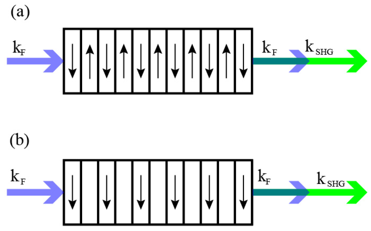
Figure 2.
Schematic of the wave vectors in quasi phase matching. In 1D (a), 2D (b) and 3D (c).
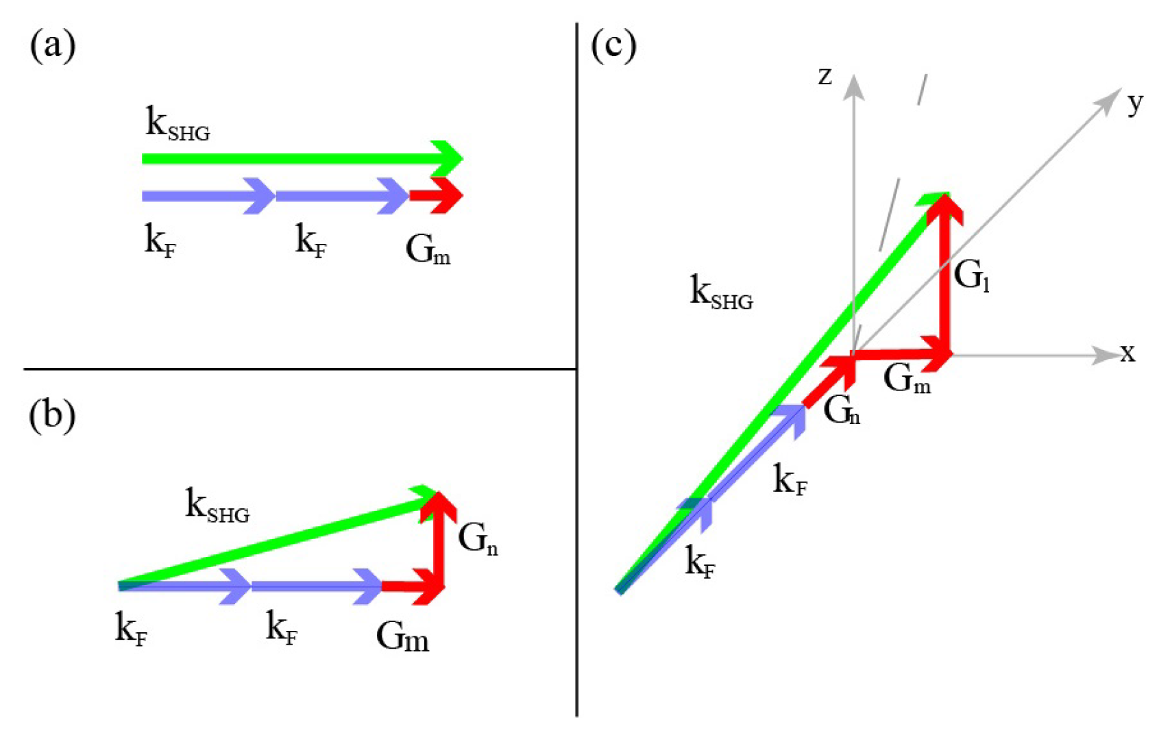
Figure 3.
Two examples of LIQPM. (a)-(c) The first -erasing grating sample. (a) Schematic of the sample and inscription setup, the coordinate system is principle axes of the crystal. (b) Outlines the inscription routine of each layer. (c) An optical microscope image of the QPM structure. The period of the grating is 19.2 m corresponding to a fundamental wavelength of 1545 nm. © 2013 WILEY-VCH Verlag GmbH & Co. KGaA, Weinheim; (d)-(f) LIQPM grating integrated with waveguide. (d) Schematic of the LIQPM waveguide design, and the grating period is 6.7 m a fundamental wavelength of 1064 nm. (e) Optical microscope images of the circular waveguide structure and (f) top view of the multiscan grating section. © 2015 AIP Publishing LIC.
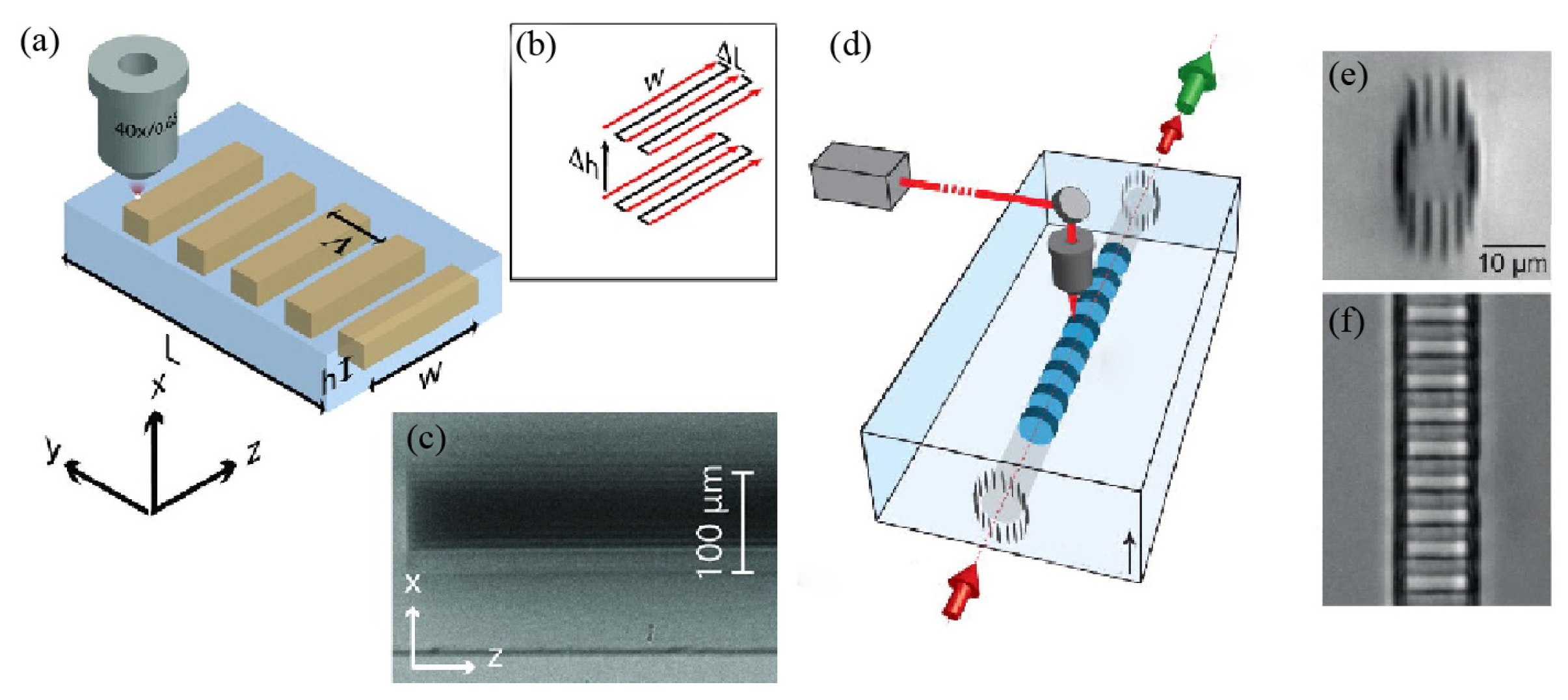
Figure 4.
Characterization of 3D NPC. (a) A erenkov SH microscopy image of the first two layers of the 3D NPC, and the inserted image showing a clear periodic structure. (b) An image in the x–y plane through a general confocal SH microscopic system. (c) The intensity distribution along the black line in (b). The average values of SH intensity are also presented in (c), the black lines. The SH intensity is much lower in the engineered area than that in the non-engineered area, which proves the reduction of due to the laser inscription. The average minimal SH intensity is 0.225, which indicates that can be further reduced. Reprinted with permission from Ref. [75], © 2018 Nature Photonics.
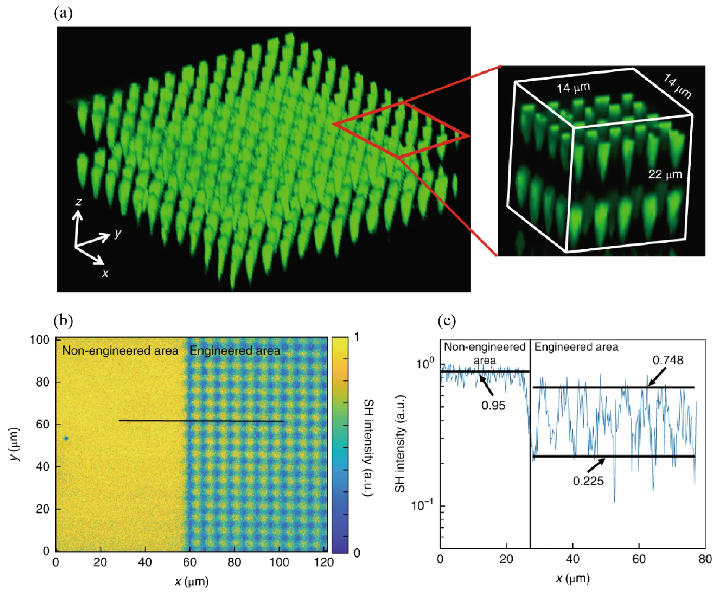
Figure 5.
Far-field diffraction patterns for the 3D nonlinear fork-grating array. (a) The erenkov SH microscopy images of the 3D structures in the xoz plane and xoy plane. Here, m. (b)-(d) SH diffraction patterns and their corresponding wave vector configurations. The 1st, 2nd, and 3rd diffraction orders are enhanced through nonlinear QPM processes at the input wavelengths of 820 nm, 802 nm and 781 nm, respectively. © 2019 Optical Society of America.
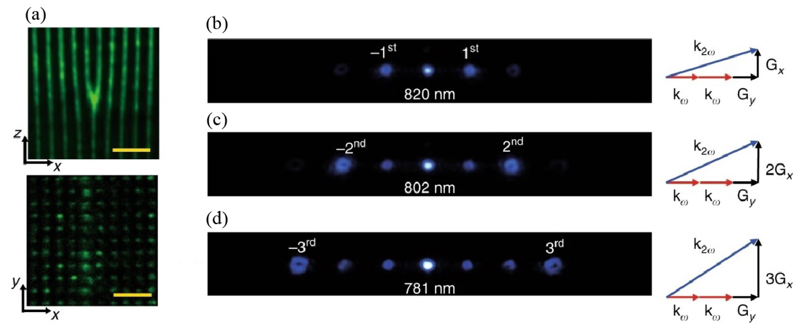
Figure 6.
Comparison of the Hermite-Gaussian patterns of HG, HG and HG. (a)-(c) Calculated patterns. (d)-(f) Optical images of the three type patterns. (g)-(i) erenkov SH microscopy images of the three type patterns. © 2019 Optical Society of America.
Figure 6.
Comparison of the Hermite-Gaussian patterns of HG, HG and HG. (a)-(c) Calculated patterns. (d)-(f) Optical images of the three type patterns. (g)-(i) erenkov SH microscopy images of the three type patterns. © 2019 Optical Society of America.
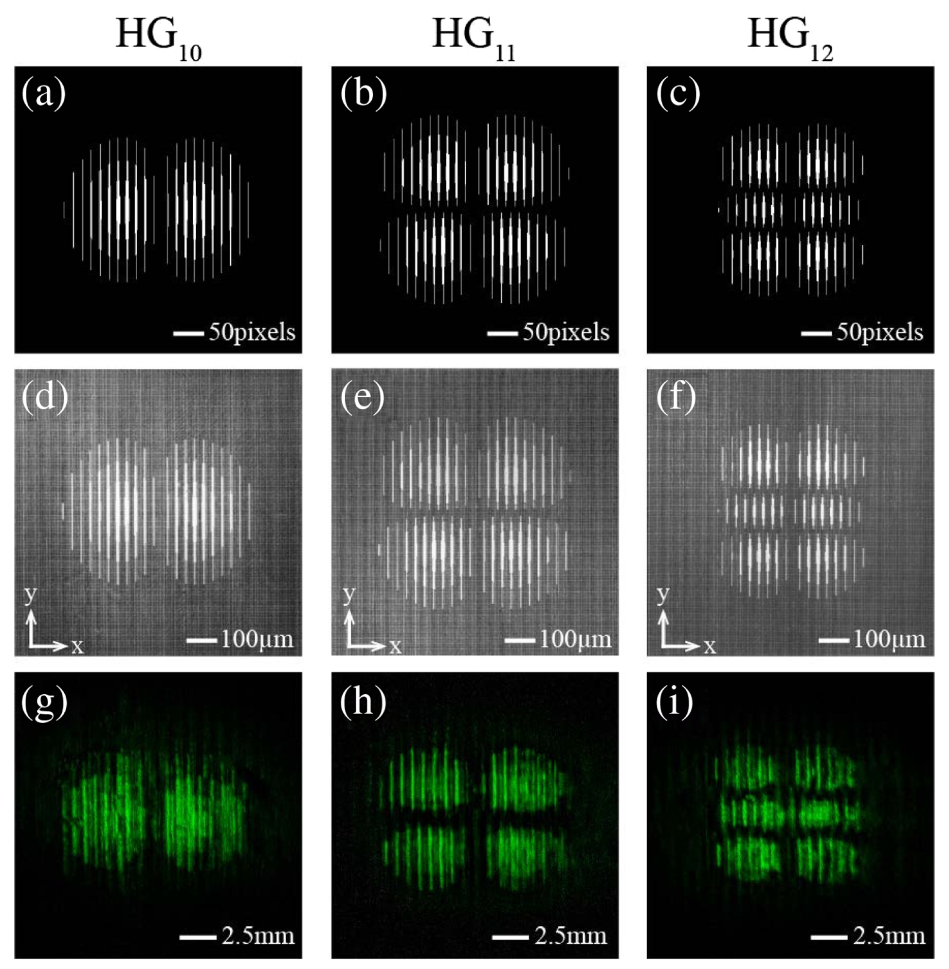
Figure 7.
Ferroelectric domain inversion induced by tightly focused femtosecond laser in the BCT crystal. (a) The -like domain structure created by femtosecond laser pulses, imaged by erenkov SH microscopy. The weak random patterns surrounding the domain originates from random inherent submicrometre-period domains in the BCT crystal. (b)-(f) Mechanism of domain inversion. (b) Temperature gradient represented by arrows in induced by nonlinear absorption in the laser focal region acts as a thermoelectric field source. (c) The z component of the temperature gradient leads a bipolar electric field. (d) When the bipolar electricfield in (c) exceeds the coercive field , it inverts microdomains in (e) to form two larger antiparallel domains in (f). Reprinted with permission from Ref. [105], © 2018 Nature Photonics.
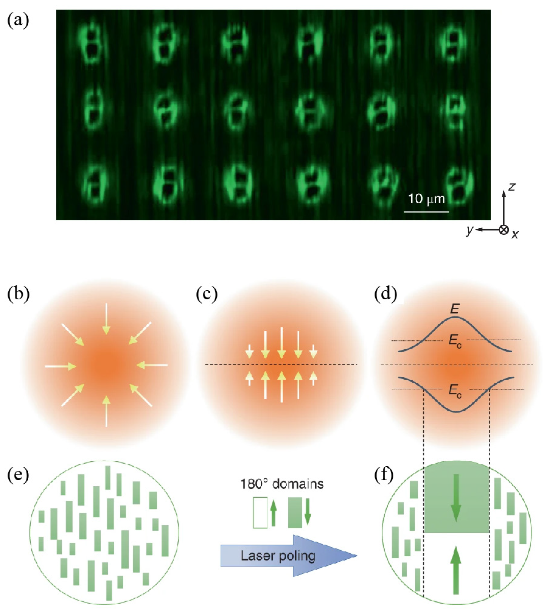
Figure 8.
Schematic of evolution of nonlinear hologram of NPC. (a) A fork pattern leads to a second harmonic emission of a standard optical vortex. (b) The fork pattern in (a) combined with an external axicon result in the formation of a perfect vortex harmonic. (c) A curved fork pattern instead of the combination in (b) also leads a perfect vortex second harmonic. © 2020 Author(s).
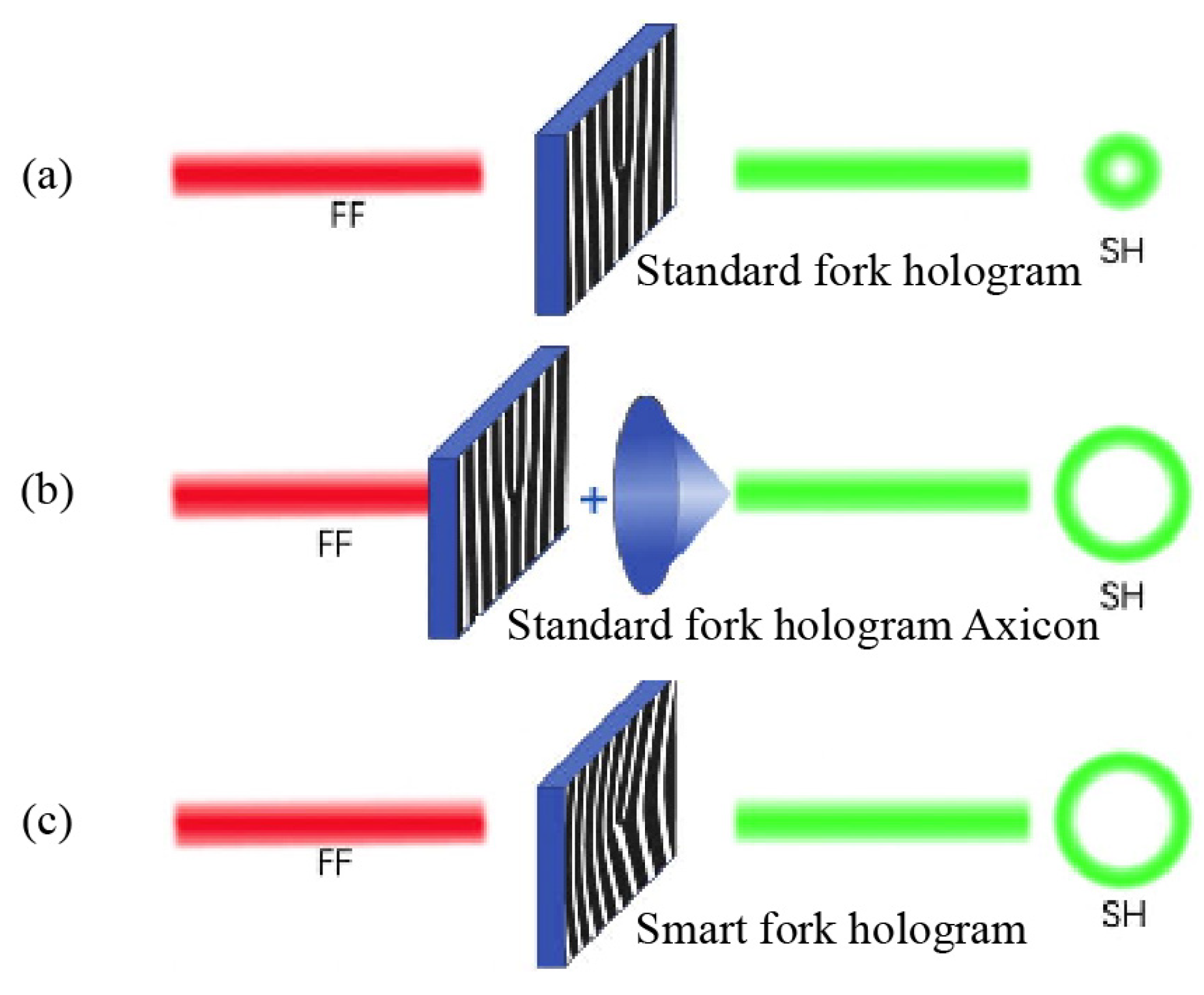
Figure 9.
The working principle of non-reciprocal laser writing for LiNbO ferroelectric domain engineering. (a)-(c) The simulated electric field. (a) The 3D thermoelectric field induced by the temperature gradient. (b) The threshold of LiNbO for domain inversion, whose magnitude depends on local temperature. (c) The z components of the thermoelectric field. Within the enclosed ellipsoidal areas, denoted by a and b, the z components and of the thermoelectric fields are higher than the threshold field. Only the one antiparallel to the spontaneous polarization of LiNbO can pole the domain. (d)-(g) The principle of the non-reciprocal laser poling and erasure in LiNbO, which strongly depends on the applying sequence of and . (d) Firstly, poles the ferroelectric domains, and very subsequently inverts the domain inverted by , resulting no inversion of the domain at the end. (e) When laser is moving along the axis, does not work, but works to invert the domain. (f) When laser scans along y axis, and separately interacts with the spontaneous polarization, leading to a inverted domain of width b. (g) Supposing that the domain is inverted at the beginning, it will be flipped back by scanning laser along axis. Reprinted with permission from Ref. [98], © 2022.
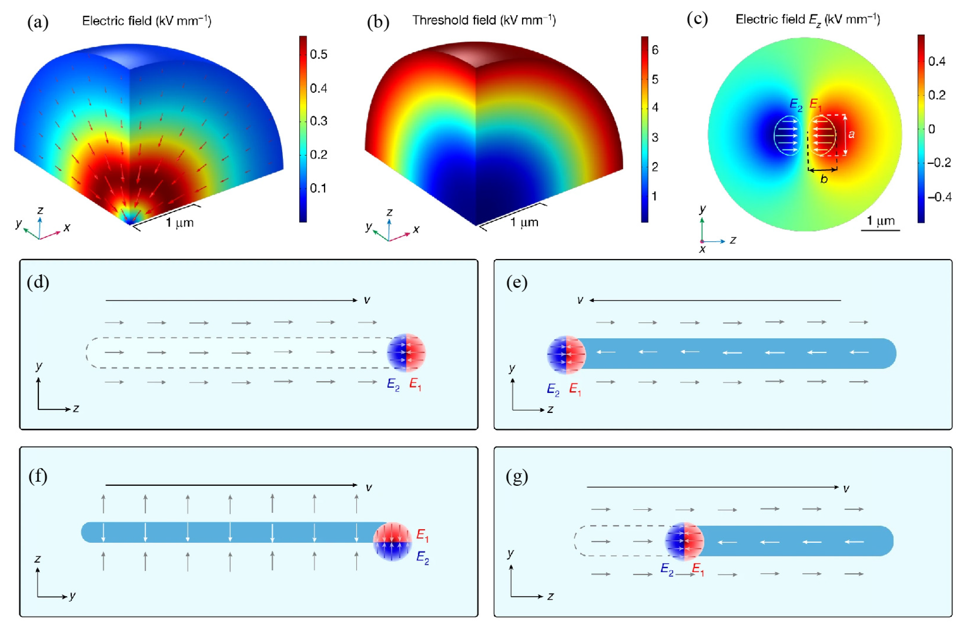
Figure 10.
The pyroelectric field changes with temperature varying. (a) The pyroelectric field is zero at room temperature. (b) It is not zero any more and parallel with the spontaneous polarization () during heating for E decreasing with temperature increasing. (c) It is zero again at C due to the electric field induced by charges. (d) It is antiparallel to the spontaneous polarization when cooling down to the room temperature. During cooling, increases and is opposite to , then the polarization is flipped when .
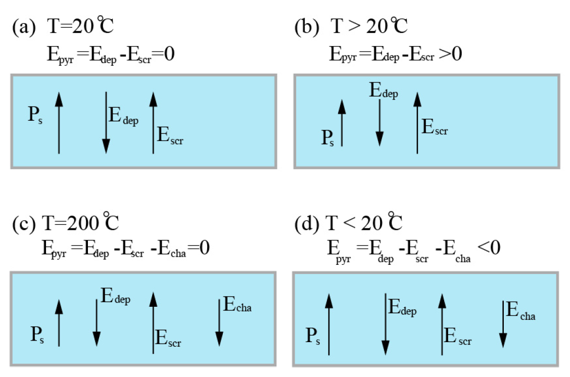
Figure 11.
Square lattic pattern with a period of 20 m. (a) Microscopy image of the lower surface of the crystal after selective chemical etching. (b) erenkov SH microscopy image of the same plane as in (a). (c) The structure in the volume of the crystal measured in 3D with the erenkov SH microscope. © 2018 Author(s).
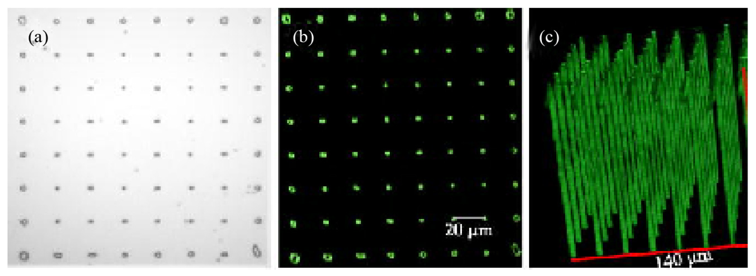
Figure 12.
erenkov SH microscopy images of the primary and secondary ferroelectric domains in PMN-38PT. (a) Laser induced domains located at different depths inside a single-domain PMN-38PT crystal. (b) The view of the cross-section corresponding to the single row squared by dashed line in (a). (c) The view of the cross-section corresponding to those dashed lines in (b). (d) Another example of secondary domain pattern. (e)-(f) Erasure of secondary domains by laser inside PMN-38PT. (e) Secondary domain formed with separation distance m. (f) Linear secondary domain patterns formed with separation distance m for the top two patterns and for the bottom one. © 2021 Wiley-VCH GmbH
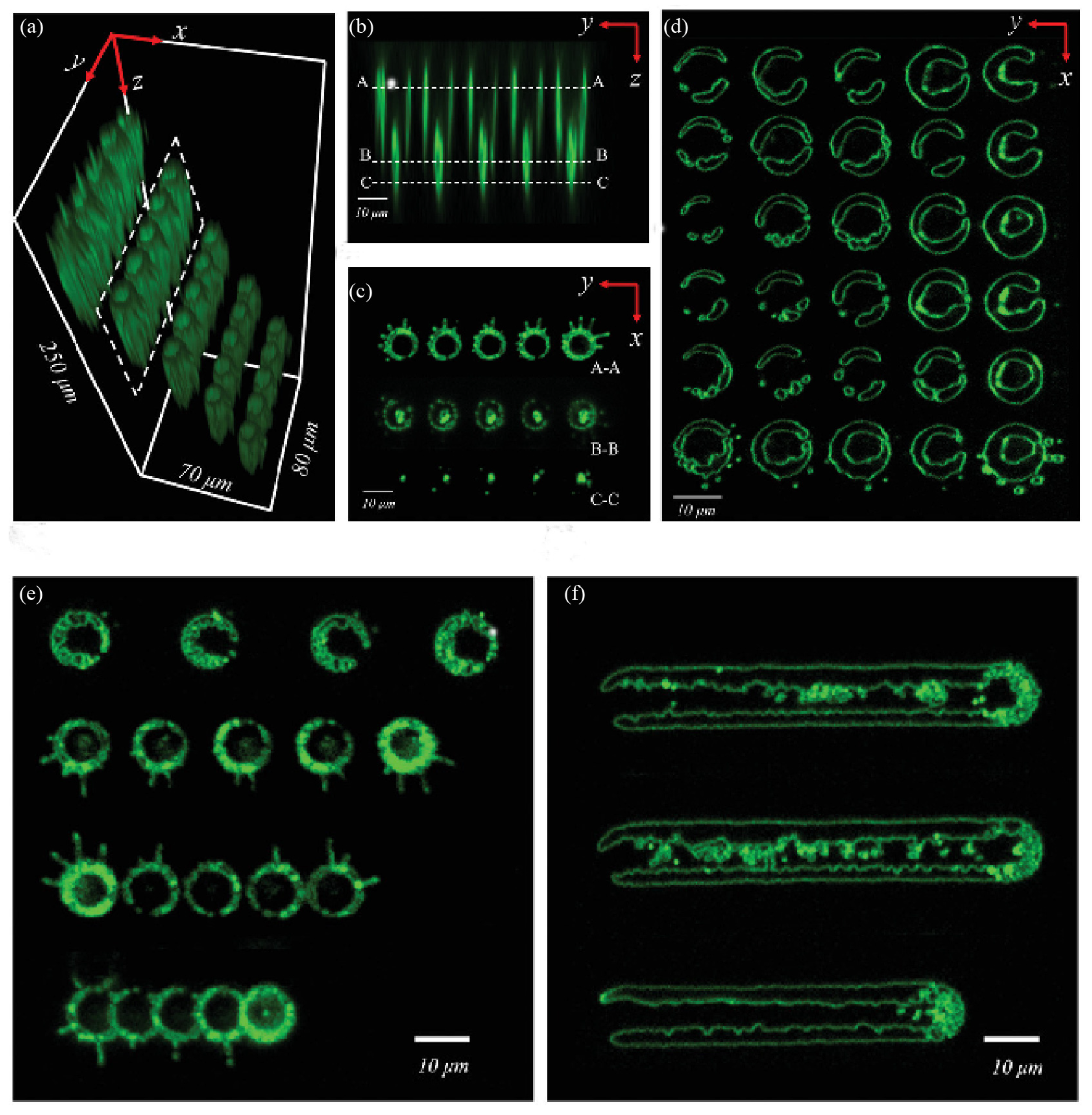

Table 1.
Selected laser writing parameters.
| -erasing | References | Nonlinear Crystal | Repeat frequency | Bandwidth | Wavelength | Pulse energy | Scan speed | N.A. |
|---|---|---|---|---|---|---|---|---|
| Ref. [72] | LiNbO | 100 kHz | 170 fs | 800 nm | 650 nJ | 1 mm/s | 0.5 | |
| Ref. [73] | LiNbO | 1 kHz | 120 fs | 800 nm | 60-72 nJ | 80 m/s | 0.8 | |
| Ref. [75] | LiNbO | 1 kHz | 104 fs | 800 nm | 100-200 nJ | 100-55 m/s | 0.8 | |
| Ref. [77] | MgO-doped LiNbO | 1 kHz | 500 fs | 1030 nm | 900 nJ | 280 m/s | 0.5 | |
| Ref. [79] | LiNbO | 200 kHz | 350 fs | 1040 nm | 16/20 nJ | 1mm/s | 0.3 | |
| Quartz | 8/12 nJ | |||||||
| -poling | References | Nonlinear Crystal | Repeat frequency | Bandwidth | Wavelength | Pulse energy | Scan speed | N.A. |
| Ref. [95] | LiNbO | 76 MHz | 180 fs | 800 nm | 0-5 nJ | 10 m/s | 0.65 | |
| Ref. [105] | BCT | 76 MHz | 180 fs | 800 nm | ~6 nJ | 10 m/s | 0.65 | |
| Ref. [109] | CBN | 76 MHz | 180 fs | 800 nm | 3.6-6.6 nJ | 10 m/s | 0.65 | |
| Ref. [120] | PMN-38PT | 80 MHz | 180 fs | 800 nm | 0-5 nJ | 0.4 | ||
| Seeds | Ref. [97] | MgO-doped LiNbO | 1 kHz | 100 fs | 800 nm | 50-500 nJ | 0.8 | |
| LM | Ref. [99] | MgO-doped LiNbO | 1000 kHz | 170 fs | 1026 nm | 150 nJ | 0.42 | |
| LI | 500 kHz | 300-900 nJ |
Disclaimer/Publisher’s Note: The statements, opinions and data contained in all publications are solely those of the individual author(s) and contributor(s) and not of MDPI and/or the editor(s). MDPI and/or the editor(s) disclaim responsibility for any injury to people or property resulting from any ideas, methods, instructions or products referred to in the content. |
© 2023 by the authors. Licensee MDPI, Basel, Switzerland. This article is an open access article distributed under the terms and conditions of the Creative Commons Attribution (CC BY) license (http://creativecommons.org/licenses/by/4.0/).
Copyright: This open access article is published under a Creative Commons CC BY 4.0 license, which permit the free download, distribution, and reuse, provided that the author and preprint are cited in any reuse.


