
Submitted:
16 May 2023
Posted:
17 May 2023
You are already at the latest version
Abstract
Keeping the bus voltage within acceptable limits depends on dispatching reactive power. Power quality improves as a result of creating an effective power flow system, which also helps to reduce power loss. Therefore, Optimal Reactive Power Dispatch (ORPD) studies aim at designing appropriate system configurations to enable a reliable operation of power systems. Establishment of such a configuration is handled through control variables in power systems. On the other hand, installing Distributed Generation Unit (DGU) into a power system can have an important effect on power quality and power loss minimization. In this paper, Grey Wolf Optimization (GWO method is applied to ORPD problem for the first time, to find optimal placement of newly installed DGUs at the power system. Active power loss and voltage minimization have been minimized by optimizing the control variables while keeping them within their upper and lower bounds, and by finding the optimal placement of a newly installed DGU in power system. On the basis of IEEE 30 bus and IEEE 118 bus systems, performance of the suggested approach is investigated. A comparison is also performed among the proposed method and some other methods. Test results demonstrate that the resulting configuration contributes to growing the rate of renewable integration to a power system. The results also indicate that the suggested optimization approach applied to ORPD problem has improved power system performance in terms of both on power loss and voltage deviation. The promising results highlight the potential of the GWO algorithm to facilitate the integration of renewable power sources, and its role in promoting sustainable energy solutions.
Keywords:
Reactive power dispatch
; optimum power flow
; grey wolf optimization (GWO)
; distributed generation units (DGUs)
; optimum placement
1. Introduction
Reactive power dispatch (RPD) is a critical operation in electric power systems, with significant implications for both safety and economic considerations [1]. Poor management of reactive power can lead to detrimental impacts on power quality and transmission losses in power systems [2,3]. Therefore, the optimization of reactive power has emerged as a fundamental strategy in reducing real power losses and plays a crucial role in both the planning and operation of power systems [4]. By effectively controlling reactive power, voltage stability can be maintained, and the reliability of real power transfer can be improved [5,6].
As power systems are designed to provide reliable power supply with economic cost, several methods or tools are used to achieve this goal. In connection with economic dispatch of power, Optimal Power Flow (OPF) was defined in 1962 by Carpentier [7,8]. ORPD is a particular case of OPF which’s goal is controlling continuous and discrete variables with adjusting generator voltage set-points, transformer tap settings, improving voltage profile and reactive compensation to reduce power loss [9,10]. ORPD problem has a big significant role on economic and secure operations of power systems. Although reactive power generation doesn’t have a production cost, but it has influence the overall generation cost of power system [11,12]. On the other hand, Distributed Generation Units (DGUs) which is currently an important concept in the economics literature about electricity markets are used to be installed on power systems for minimization of power loss [13]. DGUs connected to electric systems are set to supply reactive power based on the active power set-point. DGUs have to be allocated properly; a proper allocation will improve power quality within limits and also minimize the loss, although an inappropriate allocation will affect vice versa.
The ORPD presents itself as a challenging nonlinear optimization problem, incorporating a combination of equality and inequality constraints. Traditional methods have shown inefficiency in solving nonlinear problems therefore metaheuristic algorithms such GA [9,10], PSO [11,12], ACO [13,14], and SA [15,16] are preferred for solving ORPD problem. These algorithms are known for their global search capability, robustness, and convergence to near-optimal solutions, making them well-suited for solving ORPD problems. GA is an example of a population-based evolutionary algorithm that utilizes principles of natural selection to optimize a set of solutions towards the optimal solution. In contrast, PSO draws inspiration from the social behavior of birds or fish and employs a swarm of particles to collectively explore the solution space. ACO, inspired by the foraging behavior of ants, utilizes pheromone trails as a guiding mechanism in the search process. SA, which emulates the cooling process of a material, allows for stochastic jumps in the solution space to escape local optima.
Mathematical programming methods, such as linear programming (LP) [17,18], quadratic programming (QP) [19,20], and nonlinear programming (NLP) [21,22], have also been applied to ORPD. LP is a popular optimization approach utilized to optimize a linear objective function, while taking into account linear equality and inequality constraints. QP extends LP by allowing for quadratic objective functions and constraints, making it suitable for certain types of ORPD problems. NLP, on the other hand, handles nonlinear objective functions and constraints, but it may face challenges in solving large-scale and non-convex ORPD problems due to computational complexity and convergence issues. Hybrid approaches that integrate multiple optimization techniques have gained attention in ORPD research. For instance, hybrid algorithms that combine GA with other metaheuristic algorithms, such as GA-PSO [23,24], GA-ACO [25,26], and GA-SA [27,28], have been proposed to leverage the strengths of different algorithms and improve solution quality. These hybrid algorithms combine the global search capability of GA with the exploration and exploitation abilities of other metaheuristic algorithms, resulting in enhanced performance in solving ORPD problems.
Fuzzy logic [29,30], neural networks [31,32], and expert systems [33,34] are other methods that have been implemented to solve ORPD problems. Fuzzy logic, which deals with uncertainty and imprecision, has been used to model the vagueness associated with the decision-making process in ORPD. Neural networks, with their ability to learn from data, have been utilized for predicting and optimizing reactive power in power systems. Expert systems, which capture human expertise in the form of rules, have been employed for decision support in ORPD.
Multi-objective optimization approaches have also been used in ORPD studies. MOGA [35,36] and MOPSO [37,38] are examples of methods that optimize multiple conflicting objectives simultaneously, such as system loss, generation cost, and emission. These approaches generate a set of solutions that represent different trade-offs between the conflicting objectives, allowing decision-makers to select the most suitable solution based on their preferences [39,40].
Evolutionary strategies [41,42], which are optimization methods that mimic the process of natural selection, have been applied to solve ORPD problems as well. Evolutionary strategies employ mutation, crossover, and selection operators to evolve a set of solutions towards the optimal solution. These methods have been shown to be effective in solving large-scale and complex ORPD problems, as they can handle constraints, uncertainties, and non-convexities commonly found in real-world power systems.
Machine learning techniques, SVM [43,44], ANN [45,46], and reinforcement learning (RL) [47,48], have also been used to tackle ORPD problems. SVM, a supervised learning algorithm, has been utilized for predicting and optimizing reactive power in power systems. ANN, on the other hand, with its ability to learn from data and capture complex relationships, has been applied for reactive power dispatch and voltage control in power systems. RL, which is a type of unsupervised learning, has been used to optimize reactive power dispatch in an online and adaptive manner by learning from the system’s feedback and making decisions accordingly.
In recent years, grey wolf optimization (GWO) [49,50] has gained attention as a promising algorithm for solving ORPD problems. The GWO algorithm, drawing inspiration from the social hierarchy and hunting behavior of grey wolves, is a population-based metaheuristic. It is recognized for its rapid convergence, effective balance between exploration and exploitation, and capability to generate high-quality solutions for a variety of optimization problems, including ORPD. GWO has been applied to different variants of ORPD problems, such as multi-objective ORPD, dynamic ORPD, and uncertain ORPD, and has shown promising results in terms of computational efficiency and solution quality.
In this paper, GWO method is applied to ORPD problem for the first time, to find optimal placement of newly installed DGUs at the power system. Active power loss and voltage deviations has been minimized for optimization of the control variables while keeping them within their upper and lower bounds, and by finding the optimal placement of a newly installed DGU in power system. Two different test systems; IEEE 30-bus and IEEE 118-bus systems are used to evaluate performance of the method. The results are then compared with that of PSO, ABC, and GA optimization techniques. Therefore, the proposed GWO algorithm can effectively solve the ORPD problem by identifying optimal locations for the placement of distributed generation units (DGUs).
The primary contributions of this research work can be summarized as follows:
- Application of the GWO algorithm to solve the ORPD problem in DGU installed power systems.
- Conducting a comparative analysis of the proposed GWO method with other heuristic optimization algorithms such as GA, PSO, and ABC based on several performance metrics, including power loss minimization, voltage deviations, bus voltage levels, and number of iterations.
- Demonstration of the superior performance of the proposed GWO method in terms of converging to better optimal solutions for control variables as compared to the other heuristic methods.
- Evaluation of the effectiveness of the proposed GWO method in identifying optimal placements of DGUs, resulting in reduced power losses and improved bus voltage profiles without requiring additional measures.
- Comparison of the results obtained with and without DGUs, showing that the proposed GWO method performs better in minimizing active power losses and voltage deviations in power systems with DGUs, indicating its potential for facilitating the integration of renewable DGUs into power systems.
Overall, the findings of this research contribute to the field of power system optimization by showcasing the application and performance of the GWO method in solving the ORPD problem, and its potential for promoting the integration of renewable DGUs into power systems, thereby advancing the field of renewable energy integration in power systems.
The paper structured in the following manner: Section 2, the ORPD problem is formulated, outlining the objectives and constraints of the optimization task. Section 3 introduces the GWO technique, providing an overview of its principles and features. In Section 4, the implementation of GWO for the ORPD problem is described, including the details of how the algorithm is applied to solve the optimization task. Section 5 presents the simulations and results obtained from applying GWO to different scenarios, including the IEEE-30 bus system with 19, 25, and 27 control variables, as well as the IEEE-118 bus system. In the concluding section, the key findings and implications of the study are summarized.
2. ORPD Problem Formulation
ORPD problem is a particular case of OPF problem. In ORPD the transmission active loss is minimized by controlling generator bus voltages, transformer tap settings and size of switchable shunt capacitors [22,23]. ORPD plays an important role in securing and economizing operation of power systems [24,25]. Remaining voltage at each bus bar system within its acceptable limits maintains the quality and security in power systems [26,27]. Adjusting system variables within their upper and lower bounds so that the transmission loss is minimized can also affect overall generation cost.
This paper focuses on minimizing two objective functions: the total transmission loss (F1) and the voltage deviation at load buses (F2). These objectives are expressed as follows [16]:
Objective function (F1)
Here Nb represents number of buses in the system. PL denotes the system real power loss, Pi refers the real power injection at bus i, Pgi is the real power output of the generator which connect to bus i, Pdi is the real power load which connect to bus i.
Objective function (F2)
Mathematically, the voltage deviation of the load buses can be expressed as the sum of the voltage deviations of each load bus, denoted as VD. The voltage magnitude of the ith load bus is represented as , while refers to the reference value of voltage magnitude for bus i, which is typically assumed to be 1.0. The parameter NPQ denotes the number of PQ buses or load buses in the system. This equation quantifies the difference between the actual voltage magnitude and the desired voltage magnitude at each load bus within the power system.
Fitness function is:
Here Kf, Kv, and Kq are the penalty factors for the line flow violation, limit violation of bus voltage and generator reactive power, respectively. NPQ is the number of PQ busses Qgi is the reactive power output of the generator connecting to bus i, is the voltage magnitude at bus i , is the loading of transmission line, Ng is number of generator units, Nl is number of transmission lines.
In ORPD problem, the equality constraints are defined as active/reactive power equalities and reflects the physics of power system requiring the net injection of power at each bus to be zero as shown in equations below [28,29,30,31].
resembles the generated active power, is the demand of active power, and are the susceptance and conductance transfer between k and j.
is the reactive power generated, is the reactive power demand, N is the total number of buses
The inequality constraints reflect the limits on physical devices as well as the limits created to ensure system security, it includes bus voltage magnitude, active/reactive power generation constraints, reactive power source capacity, and transformer tap position constraints [32,33].
a)- Voltage Magnitude Constraints:
is the voltage magnitude lower limit, is the voltage magnitude of bus i, is the voltage magnitude upper limit.
b)- Active Power Generation Constraints:
Pgi denotes ith generator active power. Pgi-max and Pgi-min are the maximum and minimum active power of ith generator, respectively.
c)- Reactive Power Generation Constraints:
Qgi denotes ith generator reactive power. Qgi-max and Qgi-minare the maximum and minimum active power of ith generator, respectively.
d)- Reactive Power Source Capacity Constraints:
is shunt VAR compensation, is number of shunt VAR compensation devices, and
are the minimum and maximum limits of shunt VAR compensation.
e)- Transformer Tap Position Constraints:
is transformer tap ratio, is number of tap setting transformers, and are the minimum and maximum limit of transformer tap ratio.
3. Grey Wolf Optimization (GWO) Algorithm
GWO is a nature-inspired optimization algorithm that is based on the social behavior and hunting strategies of grey wolves developed by Mirjalili in 2014 for solving optimization problems [49]. In GWO, the population of grey wolves is modeled as a set of solutions, and the search process is guided by the interaction and collaboration among the wolves.
The algorithm mimics the hierarchical structure of a wolf pack, where alpha (α) , beta (β), delta (δ) and omega (ω) wolves represent the leaders of the pack, and their positions are updated iteratively to search for the optimal solution.
The beta provides input to the alpha while also reinforcing the alpha’s orders across the pack. The gray wolf with the lowest status, known as omega, frequently serves as a scapegoat. Additionally, they are the last wolves still permitted to consume animals. A wolf is referred to be a delta if it is not an alpha, beta, or omega. Delta wolves serve as guardians, hunters, elders, scouts, and caregivers. Figure 1 shows the gray wolf social structure. The next sub-section outlines the GWO’s social structure, tracking, surrounding, and prey-attacking steps.
Mathematical modeling of GWO Algorithm
The GWO algorithm’s mathematical model uses the α to represent the most suitable solution, while the β and δ signify the second and third best solutions, correspondingly. The remaining candidate solutions are considered as ω, which are subordinate to the α, β, and δ wolves.
The encircling behavior of wolves during hunting can be mathematically given by the following equations [50]:
In the GWO algorithm, the current iteration is denoted by the variable t, while Xp represents the position vector of the grey wolf, and X represents the position of the prey in the search space. The coefficient vectors of A and C are handled using the following expressions [5]:
The alpha (α) value exhibits a linear descent from 2 to 0 as the iterations progress, indicating a gradual reduction of this variable over time within the algorithm. This linear decrease in α controls the step size for the wolves’ movement towards the alpha wolf, leading to a decreasing exploration rate as the algorithm approaches convergence. The variables r1 and r2 are randomly generated numbers extracted from a uniform distribution spanning from 0 to 1. These random values introduce randomness and diversity in the wolves’ movement, allowing for exploration in the search space and increasing the chances of escaping local optima. During the hunting process, the pack of grey wolves updates their positions based on the best agents α, β, and δ, as well as A and C, which are handled using the random values r1 and r2, as explained above. This update process is expressed mathematically using the equations given below:
During the hunting behavior of grey wolves, they engage in attacking their prey when the prey ceases to move. This behavior can be mathematically simulated by gradually decreasing the value of a from 2 to 0. As a result, A, which varies randomly within the range of α (-1 to 1), determines the next location of the search agents. The new position is determined within the bounds of the current position of the agent and the position of the prey, typically represented as [49,50].
4. Implementation of Gwo Algorithm for Solving Orpd Problem with Dgu Placement
The ORPD problem involves determining the optimal settings of reactive power sources in a power system while minimizing an objective function, and adhering to operational constraints such as voltage limits, generator limits, and transmission line limits. This requires advanced optimization techniques and thorough analysis of the power system’s dynamic behavior.
Finding optimal settings involves optimizing output levels, voltage set points, and switching operations in real-time or near real-time, considering the uncertain nature of power system conditions. The solution to the ORPD problem has significant implications for power system stability, reliability, and efficiency, and is crucial for improving the operation and planning of modern power systems.
The GWO algorithm presents a promising approach for solving the ORPD problem in power systems, optimizing reactive power sources while considering operational constraints and uncertainty, with the potential to improve power system stability, reliability, and efficiency. As seen in Figure 2, the GWO algorithm starts with an initialization step where the algorithm parameters, such as population size, maximum number of iterations, search space limits, and convergence criteria, are set. The positions of the grey wolves, which represent the potential solutions, are randomly initialized within the search space, considering the control parameters, such as generator voltages, generator powers, tapping settings of transformers, and the location of shunt capacitors. The fitness of each grey wolf, which represents the quality of the solution, is evaluated by calculating the objective function value that represents the cost of reactive power dispatch, considering the control parameters.
Then, the algorithm enters into an iterative loop where the positions of the grey wolves are updated in regard of mathematical formulas that involve the α, β, and δ wolves, which are the best solutions found so far. The algorithm also checks for boundary violations, where a grey wolf may go beyond the search space limits or the control parameter limits, and repositions it randomly within the search space and the control parameter limits if necessary. The fitness of each grey wolf is re-evaluated, and the candidate wolves are updated based on their fitness values.
The algorithm continues to iterate until the reaching to maximum iteration or meeting convergence criteria. The convergence criteria involve checking if the mean fitness value of all the grey wolves has converged to a desired threshold. Finally, the ORPD solution is obtained from the positions of the α, β, and δ wolves, considering the control parameters, and is output as the result of the algorithm. The GWO algorithm provides a robust and efficient approach for solving the optimum reactive power dispatch problem with DGUs placement, considering the control parameters associated with generator voltages, generator powers, tapping settings, and the location of shunt capacitors.

Table 1.
Pseudocode of GWO-based Optimum Reactive Power Dispatch with DGU Placement.
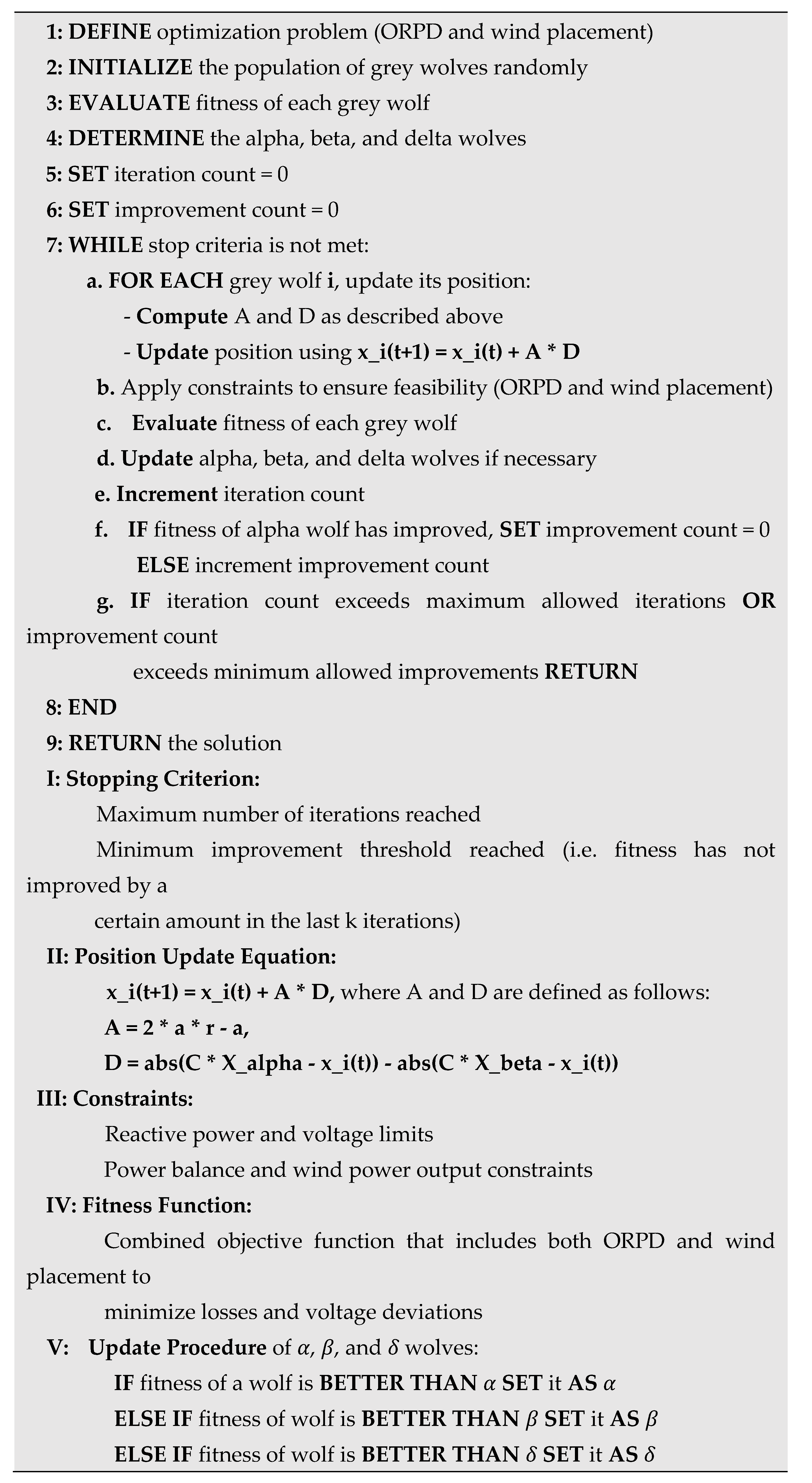 |
In this study, wind energy is chosen as the primary energy source in the DGU. The study aimed to propose a solution that maximizes the benefits of wind energy utilization in the DGU, such as improved power quality, reduced power losses, and enhanced voltage stability. The given pseudo-code outlines a solution for optimizing the reactive power dispatch (ORPD) with wind power integration using the GWO algorithm. The algorithm starts by initializing the population of grey wolves randomly, evaluating the fitness of each wolf, and determining the alpha, beta, and delta wolves. The iteration process updates the position of each wolf using a position update equation and applies constraints to ensure feasibility of both reactive power dispatch and wind placement. The fitness of each wolf is evaluated and the α, β, and δ wolves are updated if necessary. The stopping criterion is based on a maximum number of iterations and a minimum improvement threshold. The algorithm returns the optimal solutions for reactive power dispatch and wind placement, along with the total system loss and voltage deviation. The proposed approach can provide an efficient solution to the OPRD problem with wind integration.
5. Simulation Results and Discussion
In this study, verifications were conducted by referencing the IEEE 30-bus and 118-bus test systems. The primary objective of choosing these test systems is to evaluate the efficacy of the GWO method in comparison to other existing optimization methods in addressing the ORPD problem. The standard IEEE 30-bus system is composed of 5 PV buses, 21 loads, 41 branches, 4 tap changers, and 3 shunt capacitors, as reported in [1,51,52]. Another test system used in this study is the IEEE 118-bus system, which consists of 54 PV buses, 99 loads, 186 branches, 9 tap changers, and 14 shunt VAR compensators [53,54,55].
IEEE-30 Bus System
- Scenario 1: Results of the IEEE-30 bus system with 19 control variables
The system data are presented in [1,51,52]. According to the given scenario, 19 control variables are considered. These control variables are as follows:
- 6 variables of generator bus voltages
- 4 variables of transformer tap settings
- 9 variables of reactive power of the VAR compensators
As seen in Table 2, the voltages are bounded by a minimum of 0.90 and a maximum of 1.10 per unit (p.u.), with 1.10 being the upper threshold and 0.90 being the lower threshold. Similarly, the transformer taps are restricted within a range of 0.9 to 1.1, where 1.1 signifies the upper limit and 0.9 signifies the lower limit. The VAR compensators are constrained with a lower limit of 0 MVARs and an upper limit of 7 MVARs, respectively.
As seen in Table 3, the proposed GWO algorithm demonstrated a significant percentage improvement in both total loss and voltage deviation compared to PSO, GA, and ABC methods. Specifically, the GWO method achieved a percentage improvement of 11.55%, 21.99%, and 10.14% in total loss compared to PSO, GA, and ABC, respectively. Similarly, the GWO method achieved a percentage improvement of 210.54%, 1.62%, and 57.09% in voltage deviation compared to PSO, GA, and ABC, respectively.
In the proposed GWO algorithm, the number of agents is an important parameter that affects the optimization performance. Increasing the number of agents can help to improve the exploration ability of the algorithm and increase the probability of finding the global optimal solution. However, increasing the number of agents also increases the computational complexity of the algorithm.
The conducted study investigated the effect of the number of agents on the convergence behavior of the GWO algorithm, and convergence curves were plotted using different numbers of agents. The results showed that increasing the number of agents led to faster convergence and improved optimization performance. However, this also resulted in increased computational time, which could limit the practical application of the algorithm. Selecting an appropriate number of agents is crucial in balancing the trade-off between computational complexity and performance in the GWO algorithm for optimization.
As shown in Figure 3 of the study, the proposed GWO algorithm demonstrated excellent convergence performance for Scenario 1 of the IEEE-30 test system, with agent numbers of 20, 30, and 40. These results suggest that the GWO algorithm efficiently converges, and holds promising potential in solving optimization problems for various test systems. The obtained convergence curves in the study can provide insights into selecting the optimal number of agents for the GWO algorithm in various optimization problems.
- Scenario 2: Results of the IEEE-30 bus system with 25 control variables
The system data are presented in [51,56]. According to the given scenario, 25 control variables are considered. These control variables are as follows:
- 6 variables of generated power
- 6 variables of generator bus voltages
- 4 variables of transformer tap settings
- 9 variables of reactive power of the VAR compensators
As seen in Table 4, the lower and upper limits of the generated power value range from 0.05 p.u. to 1.00 p.u. The voltages are bounded by a minimum of 1.00 and a maximum of 1.10 p.u. with 1.10 being the upper threshold and 1.00 being the lower threshold. Similarly, the transformer taps are restricted within a range of 0.9 to 1.1, where 1.1 signifies the upper limit and 0.9 signifies the lower limit. The VAR compensators are constrained with a lower limit of 0 MVARs and an upper limit of 5 MVARs, respectively.
According to the results provided, the GWO (proposed) algorithm outperforms the ABC algorithm in terms of both total loss and voltage deviation. The total loss for GWO (proposed) is significantly reduced by 46.96% compared to ABC, while the voltage deviation is improved by 5.99%. These findings suggest that the GWO (proposed) algorithm offers superior performance in minimizing total loss and voltage deviation, indicating its effectiveness for power system optimization. The percentage improvements in both total loss and voltage deviation highlight the potential of the GWO (proposed) algorithm as a promising optimization technique for power system applications, potentially leading to more efficient and reliable power system operations.
The power loss convergence analysis of the GWO (proposed) algorithm, as depicted in Figure 4, reveals its remarkable performance in achieving convergence for Scenario 2 of the IEEE-30 test system, employing varying agent numbers such as 20, 30, and 40.
The voltage deviation convergence analysis of the GWO (proposed) algorithm, as depicted in Figure 5, reveals its remarkable performance in achieving convergence for Scenario 2 of the IEEE-30 test system, employing under 40 agents. The results indicate that the GWO algorithm not only achieves low total power loss (2.0679 MW) but also exhibits minimal voltage deviation (0.9769 pu), underscoring its effectiveness in optimizing both power loss and voltage deviation simultaneously.
- Scenario 3: Results of the IEEE-30 bus system with 27 control variables (wind integration)
The IEEE-30 bus system with 27 control variables is an extended version of IEEE-30 bus system that incorporates two additional DGU control variables. These variables are the generator voltage magnitude control and the generator power control. According to the given scenario, 27 control variables are considered. These control variables are as follows:
- 7 variables of generated power with wind power
- 7 variables of generator bus voltages with wind bus
- 4 variables of transformer tap settings
- 9 variables of reactive power of the VAR compensators
The Table 6 provides the lower and upper limits for variables such as wind power, generated power, voltages, tap settings, and compensation devices. These limits define the constrained ranges for each variable during the optimization process, guiding the optimization to achieve optimal results within these limits for improved system performance.
The Table 7 provides an analysis of the performance of the GWO (proposed) algorithm on the control variables for the IEEE-30 test system scenario, including voltage deviation and total loss of power. The table presents the lower and upper limits for each control variable, as well as the results obtained by the GWO algorithm within these limits.
The GWO (proposed) algorithm effectively operates within the specified limits for all control variables, including Pwind and Vwind.
The inclusion of a DGU unit (0-10 MW) with wind power and wind bus voltage control parameters in the GWO (proposed) algorithm for optimizing IEEE 30 scenario 2 without modifying generator power values resulted in wind power control at 9.8 MW and wind bus voltage at 1.0604 pu among 27 optimized control variables. This suggests effective incorporation of DGU unit and control parameters by GWO, leading to satisfactory results in the IEEE 30 test system scenario. Total power loss is 1.8010 MW, and voltage deviation is 1.0154 pu, indicating successful optimization of control variables for the IEEE-30 test system.
The power loss convergence analysis of the GWO (proposed) algorithm, as depicted in Figure 6, reveals its remarkable performance in achieving convergence for Scenario 3 of the IEEE-30 test system, employing varying agent numbers such as 20, 30, and 40. The figure depicts the convergence values plotted up to 250 iterations for all agent numbers. Notably, it has been observed that the GWO (proposed) algorithm with 40 agents achieves the complete convergence value after only 100 iterations, showcasing the remarkable rapid convergence capability of the proposed algorithm.
Similary, the voltage deviation convergence analysis of the GWO (proposed) algorithm, as depicted in Figure 7, reveals its remarkable performance in achieving convergence for Scenario 3 of the IEEE-30 test system, employing for 40 agents.
In the IEEE 30-bus test system, distributed generation units (DGUs) with wind power as a renewable energy source are connected to the buses, except for buses 1, 2, 5, 8, 11, and 13. Power loss values were observed for each bus. It was observed that the DGU connected to bus 21 caused the lowest power loss, with a value of 1.801 MW. The largest power loss was determined to occur with the DGU connected to bus 9, with a loss value of 3.393 MW. Therefore, the power loss difference between the DGU connected to bus 9 and the DGU connected to bus 21 is approximately 88.34% based on the observed values. Consequently, the implementation of the GWO method in the ORPD process yields favorable outcomes, including the simultaneous mitigation of power loss and voltage deviation, as well as the optimization of DGU placement, contributing to enhanced integration of renewable energy sources.
IEEE-118 Bus System
- Scenario 1: Results of the IEEE-118 bus system with 77 control variables
The system data are presented in [53,54,55,56]. According to the given scenario, 77 control variables are considered. These control variables are as follows:
- 54 variables of generator bus voltages
- 9 variables of transformer tap settings
- 14 variables of reactive power of the VAR compensators
Table 8 shows the limit settings for control variables in the IEEE-118 system. The lower limit for generator bus voltages is set at 0.95 p.u, while the upper limit is set at 1.10 p.u. Transformer tap settings are constrained within a lower limit of 0.90 p.u. and an upper limit of 1.10 p.u. Likewise, the compensation devices are bounded by -20 MVAR and 20 MVAR as the lower and upper limits, respectively. These threshold values serve as critical parameters in regulating the operation of the power system, ensuring stability and reliability.
According to the IEEE 118-bus test system, GWO (proposed) algorithm exhibits a significant improvement in power loss reduction compared to ABC, PSO, and GSA algorithms. GWO algorithm achieves the lowest power loss with a reduction of approximately 24.86% compared to ABC, 20.21% compared to PSO, and 16.40% compared to GSA, indicating its superiority in optimizing the power flow of the system. This suggests that GWO algorithm can be a promising choice for power system optimization, particularly in minimizing power losses and improving system efficiency. The results imply that GWO algorithm exhibits potential as an effective solution for power system optimization, with a notable capability in minimizing power losses and enhancing overall system efficiency.
The convergence analysis of the proposed GWO algorithm, as shown in Figure 9, demonstrates its impressive performance in achieving convergence in Scenario 1 of the IEEE-118 test system with varying agent numbers (20, 30, and 40). The figure displays the convergence values plotted up to 1000 iterations for all agent numbers. Remarkably, the GWO (proposed) algorithm with 40 agents achieves the complete convergence value in just 229 iterations, highlighting the exceptional rapid convergence capability of the proposed algorithm.
Figure 10 presents the convergence analysis of voltage deviation for Scenario 1 of the IEEE-118 test system, utilizing the GWO (proposed) algorithm with 40 agents. The results highlight the outstanding performance of the algorithm in achieving convergence, with the voltage deviation value reaching a remarkable low of 1.09356 pu. This indicates the robustness and accuracy of the proposed algorithm in optimizing voltage levels and minimizing deviations, making it highly effective for power system optimization tasks.
- Scenario 2: Results of the IEEE-118 bus system with 131 control variables
The system data are presented in [53,54,55,56]. According to the given scenario, 131 control variables are considered. These control variables are as follows:
- 54 variables of generated power
- 54 variables of generator bus voltages
- 9 variables of transformer tap settings
- 14 variables of reactive power of the VAR compensators
Table 10.
Limit Setting for Control Variables for IEEE-118 System in Scenario 2.
| Variables | Lower Limit | Upper Limit |
|---|---|---|
| Generated Power | 0.05 pu | 3.60 pu |
| Voltages | 0.95 pu | 1.10 pu |
| Tap Settings | 0.90 pu | 1.10 pu |
| Compensation Devices | -20 MVAR | 20 MVAR |
The table presents the variables and their corresponding lower and upper limits in the context of power system analysis. The lower and upper limits of generated power are set at 0.05 pu and 3.60 pu, respectively, indicating that the generated power must be within this range. Similarly, the voltages in the system must be maintained between 0.95 pu and 1.10 pu. The tap settings for voltage regulating devices are constrained within the range of 0.90 pu to 1.10 pu. Lastly, the compensation devices are limited to -20 MVAR to 20 MVAR, signifying the acceptable range for reactive power compensation. These limits play a crucial role in ensuring the stability and reliability of the power system operation by regulating the values of these variables within acceptable bounds.
As seen in Table 11 that using the GWO algorithm shows that keeping control variables within their specified limits resulted in a significantly lower power loss (68.1578 MW) compared to the IEEE-118 test system without power control parameters. After 213 iterations, the GWO algorithm was able to find the optimal values for the control variables, which remained optimal until the end of the simulation at 1000 iterations. This indicates that the GWO algorithm successfully optimized the system by finding optimal values for control variables while respecting their limits. The results suggest that the GWO algorithm has the potential to improve power system performance by minimizing power losses.
- Scenario 3: Results of the IEEE-118 system with 133 control variables (wind integration)
The IEEE-118 bus system has been expanded to include two new control variables that specifically target Distributed Generation Units (DGUs). These variables are the generator voltage magnitude control and the generator power control. With these additions, the system now boasts a total of 133 control variables, making it an extended version of the original IEEE-118 bus system. According to the given scenario, 133 control variables are considered. These control variables are as follows:
- 55 variables of generated power with wind power
- 55 variables of generator bus voltages with wind bus
- 9 variables of transformer tap settings
- 14 variables of reactive power of the VAR compensators
Table 12 shares the same values as Table 11 for generated powers, generator bus voltages, transformer tap settings, and compensation values, while generated power values are constrained within a lower limit of 0.05 p.u. and an upper limit of 3.60 p.u. In Scenario 3, an additional distributed generation unit (DGU) powered by wind energy is introduced into the system, with a power output ranging from 0 to 0.5 per unit (50 MW).
According to the Table 13 results, the GWO algorithm successfully minimized power losses with a value of 28.1372 MW, while keeping voltage deviation within acceptable limits with a value of 1.12945 pu. The ability of the GWO algorithm to optimize the control variables within their specified limits demonstrates its potential to enhance power system performance. By minimizing power losses and maintaining acceptable voltage levels, the GWO algorithm can improve the reliability and efficiency of power systems.
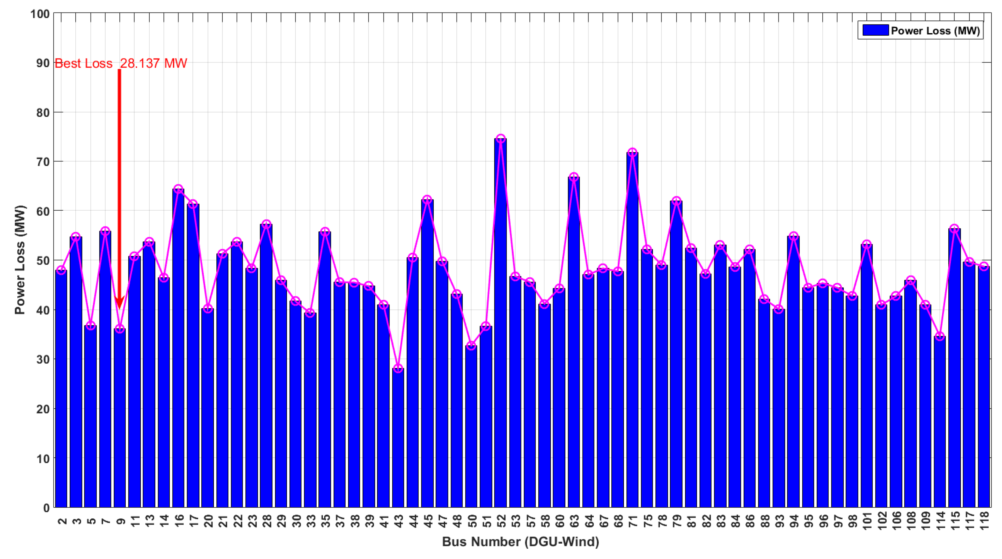
In the IEEE 118-bus system of Scenario 3, the integration of distributed generation units (DGUs) utilizing wind power has been investigated. These DGUs are connected to the buses, except for standard PV buses, highlighting the potential for renewable energy sources to be utilized in power systems. As seen in Figure 12, the results revealed that the placement of DGUs significantly affects the overall power loss of the system. Notably, the DGU connected to bus 9 resulted in the lowest power loss of 28.1372 MW, while the highest power loss of 74.59583 MW was observed with the DGU connected to bus 52, indicating a significant difference of approximately 165.4%. These findings highlight the importance of carefully selecting the location of DGUs in order to optimize system performance and maximize renewable energy utilization.
Figure 11.
Power loss convergence patterns for Scenario3 of the IEEE 118-bus system (wind integration).
Figure 11.
Power loss convergence patterns for Scenario3 of the IEEE 118-bus system (wind integration).
The use of the GWO algorithm in the optimization process has yielded promising results. Specifically, the GWO algorithm has facilitated the simultaneous mitigation of power loss and voltage deviation, while also optimizing DGU placement. This successful implementation of the GWO algorithm has contributed to the efficient integration of renewable energy sources into the power system, leading to enhanced system performance and increased utilization of renewable energy. Overall, these results demonstrate the potential of the GWO algorithm as a powerful tool for optimizing power system operation and promoting sustainable energy solutions. Further research is needed to investigate the applicability of the GWO algorithm to other power systems and to explore the potential for further improvements in renewable energy integration.
6. Conclusions
In this study, the proposed GWO method aims to address the ORPD problem by determining the optimal placement of distributed generation units (DGUs) in a power system. The optimization process focuses on minimizing both the active power loss and voltage deviations, while ensuring that the control variables remain within their designated upper and lower bounds. This approach aims to optimize the operation of DGUs in the power system to maximize the integration of renewable energy sources and minimize the associated losses.
To assess the performance of the proposed method, the authors utilized the IEEE 30 bus and IEEE 118 bus systems as case studies in their investigation. A comparison was conducted with other heuristic methods such as GA, PSO, and ABC in terms of various performance metrics including power loss minimization, voltage deviations, bus voltage levels, and number of iterations. The results obtained from the comparison highlight the potential of the proposed GWO based method in improving the performance and efficiency of power systems with increased renewable energy penetration. The reduced number of iterations needed for convergence is a notable advantage in terms of computational efficiency and practical implementation. These findings contribute to the understanding of the applicability and effectiveness of the GWO-based approach in addressing the ORPD problem and optimizing the placement of DGUs in power systems to promote renewable energy integration.
In conclusion, the proposed GWO-based optimization method offers promising results in optimizing the placement of DGUs in a power system for achieving optimal renewable penetration and dispatch. The comparison with other methods and the evaluation of performance metrics support the effectiveness and efficiency of the proposed approach. The results obtained from this study can provide valuable insights for researchers and practitioners in the field of power systems planning and operation, with the aim of promoting renewable energy integration in power systems.
Competing Interests
The authors declare no competing interests.
Author Contributions
All authors have contributed equally to the work.
References
- Zimmerman, R.D.; Murillo-Sánchez, C.E.; Thomas, R.J. MATPOWER: Steady-State Operations, Planning and Analysis Tools for Power Systems Research and Education. IEEE Trans. Power Syst. 2011, 26, 12–19. [Google Scholar] [CrossRef]
- Zhu, J. Optimization of power system operation; John Wiley Sons: Hoboken, NJ, USA, 2015. [Google Scholar]
- Maskar, M.B.; Thorat, A.R.; Korachgaon, I. A review on optimal power flow problem and solution methodologies, International Conference on Data Management, Analytics and Innovation (ICDMAI) 2017, 64-70, IEEE.
- Ting, Chuan-Kang, On the Mean Convergence Time of Multi-Parent Genetic Algorithms without Selection, In European Conference on Artificial Life, 2005, 403-412, Springer, Berlin, Heidelberg.
- T. Van Cutsem and C. Vournas, Voltage Stability of Electric Power Systems. New York: Springer, 1998.
- M. Glavic, T. M. Glavic, T. Van Cutsem, “Some Reflections on Model Predictive Control of Transmission Voltages” In Proc. of the 38th North American Power Symposium (38th NAPS), Carbondale, USA, Sept. 2006.
- Carpentier, J. Contribution to the economic dispatch problem. Bull. Soc. Franc. Elect. 1962, 8, 431–447. [Google Scholar]
- Carpentier, J. Optimal power flows. Int. J. Electr. Power Energy Syst. 1979, 1, 3–15. [Google Scholar] [CrossRef]
- Kou, X. Particle Swarm Optimization Based Reactive Power Dispatch for Power Networks with Distributed Generation. Master Thesis, University of Denver, USA, 2015. [Google Scholar]
- Norshahrani, M.; Mokhlis, H.; Abu Bakar, A.; Jamian, J.; Sukumar, S. Progress on Protection Strategies to Mitigate the Impact of Renewable Distributed Generation on Distribution Systems. Energies 2017, 11, 1864–1894. [Google Scholar] [CrossRef]
- Al Rashidi, M.R.; El-Hawary, M.E. A Survey of Particle Swarm Optimization Applications in Electric Power Systems. IEEE Trans. Evol. Comput. 2009, 13, 913–918. [Google Scholar] [CrossRef]
- Salama, M.M.A.; Manojlovic, N.; Quintana, V.H.; Chikhani, A.Y. Real-Time Optimal Reactive Power Control for Distribution Networks. Electr. Power Energy Syst. 1996, 18, 185–193. [Google Scholar] [CrossRef]
- Radosavljević, J.; Jevtić, M.; Milovanović, M. A solution to the ORPD problem and critical analysis of the results. Electr. Eng. 2018, 100, 253–265. [Google Scholar] [CrossRef]
- Oo, K.Z.; Lin, K.M.; Aung, T.N. Particle Swarm Optimization Based Optimal Reactive Power Dispatch for Power Distribution Network with Distributed Generation. Int. J. Energy Power Eng. 2017, 6, 53–60. [Google Scholar] [CrossRef]
- Gutiérrez, D.; Villa, W.M.; López-Lezama, J.M. Optimal reactive power dispatch by means of particle swarm optimization. Inf. Tecnol. 2017, 10, 215–224. [Google Scholar] [CrossRef]
- Sivalingam, C.M.K.; Ramachandran, S.; Rajamani, P.S.S. Reactive Power Optimization in a Power System Network Through Metaheuristic Algorithms. Turk. J. Electr. Eng. Comput. Sci. 2017, 25, 4615–4623. [Google Scholar] [CrossRef]
- Dutta, S.; Roy, P.K.; Manna, D.K. HBBO Optimization for Optimal Reactive Power Dispatch Incorporating TCSC and TCPS Devices, Michael Faraday IET International Summit, 2015, 156–163, Kolkata, India. [CrossRef]
- Cao, Y.J.; Wu, Q.H. Optimal Reactive Power Dispatch Using an Adaptive Genetic Algorithm, 1997, 117-122. [CrossRef]
- El-Ela, A.A.; Kinawy, A.M.; El-Sehiemy, R.A.; Mouwafi, M.T. Optimal reactive power dispatch using ant colony optimization algorithm. Electr. Eng. 2011, 93, 103–116. [Google Scholar] [CrossRef]
- Khanmiri, D.T.; Nasiri, N.; Abedinzadeh, T. Optimal Reactive Power Dispatch Using an Improved Genetic Algorithm. Int. J. Comput. Electr. Eng. 2012, 4, 463–472. [Google Scholar]
- Esmin, A.A.; Lambert-Torres, G.; De Souza, A.Z. A hybrid particle swarm optimization applied to loss power minimization. IEEE Trans. Power Syst. 2005, 20, 859–866. [Google Scholar] [CrossRef]
- Sharif, S.S.; Taylor, J.H. Dynamic optimal reactive power flow, In American Control Conference 1998, 6, 3410–3414.
- Turkay, B.E.; Cabadag, R.I. Optimal Power Flow Solution Using Particle Swarm Optimization Algorithm, In EUROCON, 2013, 1418-1424.
- Om, H.; Shukla, S. Optimal Power Flow Analysis of IEEE-30 Bus System Using Soft Computing Techniques, International Journal of Engineering Research Science (IJOER), 2015, 8, 55–60.
- Ayan, K.; Kılıç, U. Artificial Bee Colony Algorithm Solution for Optimal Reactive Power Flow, Applied Soft Computing, 2012, 12,1477–1482. [CrossRef]
- El-Shimy, M.; Abuel-wafa, A.R. Implementation and Analysis of Genetic Algorithms (GA) to the Optimal Power Flow (OPF) Problem, Scientific Bulletin-Faculty of Engineering-Ain Shams University, 2006, 41, 753–771.
- Durairaj, S.; Kannan, P.S.; Devaraj, D. Application of Genetic Algorithm to Optimal Reactive Power Dispatch including Voltage Stability Constraint, Journal of Energy Environment. 2005, 4, 63–73.
- Mamandur, K.R.C.; Chenoweth, R.D. Optimal Control of Reactive Power Flow for Improvements in Voltage Profiles and for Real Power Loss Minimization, IEEE Transactions on Power Apparatus and Systems, 1981, 7, 3185–3194. [CrossRef]
- Kumar, C.; Raju, C.P. Constrained Optimal Power Flow Using Particle Swarm Optimization, International Journal of Emerging Technology and Advanced Engineering, 2012, 2, 235–241. [CrossRef]
- Dai, C.; Chen, W.; Zhu, Y.; Zhang, X. Seeker Optimization Algorithm for Optimal Reactive Power Dispatch, IEEE Transactions on Power Systems, 2009, 24, 1218–1231. [CrossRef]
- Le Dinh, L.; Vo Ngoc, D.; Vasant, P. Artificial Bee Colony Algorithm for Solving Optimal Power Flow Problem, The Scientific World Journal, 2013, 1-9.
- Mouassa, S.; Bouktir, T. Artificial Bee Colony Algorithm for Discrete Optimal Reactive Power Dispatch, Proceedings of International Conference in Industrial Engineering and Systems Management, 2015, 654-662. [CrossRef]
- Dieu, V.N.; An, N.H.T.; Kien, V.T. Optimal Reactive Power Dispatch Using Artificial Bee Colony Method, Gmsarn International Journal, 2015, 9, 29–36.
- Monti, A.; Ponci, F. Electric Power Systems. In Intelligent Monitoring, Control, and Security of Critical Infrastructure Systems, Springer, Berlin, and Heidelberg, 2015, 31-65. [CrossRef]
- Zhang, X.P. Electric Power System Analysis. Oper. Control. -Electr. Eng. 2006, 2, 1–42. [Google Scholar] [CrossRef]
- Gautam, L.K.; Mishra, M.; Bisht, T. A Methodology for Power Flow & Voltage Stability Analysis, International Research Journal of Engineering and Technology (IRJET), 2015, 2, 321–326.
- Ling, S.H.; Iu, H.H.; Chan, K.Y.; Lam, H.K.; Yeung, B.C.; Leung, F.H. Hybrid particle swarm optimization with wavelet mutation and its industrial applications. IEEE Trans. Syst. Man Cybern. Part B 2008, 38, 743–763. [Google Scholar] [CrossRef]
- Abido, M.A. Optimal power flow using particle swarm optimization, International Journal of Electrical Power & Energy Systems, 2002, 24, 563–571. [CrossRef]
- Lee, K.Y.; El-Fergany, A.A.; Lee, J.H. Optimal power flow with a coordinated control of distributed energy resources: A review. Energies 2018, 11, 1221. [Google Scholar] [CrossRef]
- Sánchez-Fernández, M.; Carro-Calvo, L.; Pérez-García, J.; Alcarria, R. A review of optimization methods for reactive power dispatch in power systems. Energies 2019, 12, 2343. [Google Scholar] [CrossRef]
- Beyer, H.-G. (1995). The theory of evolution strategies. Springer Science & Business Media.
- Hansen, N.; Ostermeier, A. (2001). Completely derandomized self-adaptation in evolution strategies. Evolutionary computation, 9(2), 159-195.
- Zhang, J.; Liu, Y.; Wen, F. (2013). An SVM-based approach for reactive power optimization in power systems. Electric Power Systems Research, 95, 45-51.
- Li, Z.; Sun, H.; Li, Y.; Li, Q. (2016). A reactive power optimization method based on support vector machines. International Journal of Electrical Power & Energy Systems, 75, 1-7.
- Liu, Y.; Cai, X.; Zhang, W. (2016). A neural network approach for voltage control in distribution systems with renewable energy integration. International Journal of Electrical Power & Energy Systems, 83, 121-127.
- Zhao, F.; Wu, W.; Dong, Z.Y. (2017). Artificial neural network-based reactive power optimization in large-scale power systems. International Journal of Electrical Power & Energy Systems, 92, 30-38.
- Yang, Z.; Chen, H.; Zhao, B. (2017). Reinforcement learning based reactive power optimization for active distribution network. Energy Procedia, 142, 2483-2488.
- Xiong, Q.; Liu, Y.; Sun, H. (2019). Reinforcement learning-based reactive power optimization considering load and renewable energy uncertainty. IEEE Transactions on Power Systems, 34(6), 4636-4647.
- Mirjalili, S.; Mirjalili, S.M.; Lewis, A. (2014). Grey wolf optimizer. Advances in engineering software, 69, 46-61.
- Li, Y.; Li, X.; Yu, D. Grey wolf optimizer-based reactive power optimization of power systems with wind power. Applied Energy 2017, 185, 1791–1801. [Google Scholar]
- Mohseni-Bonab, S.M.; Rabiee, A.; Mohammadi-Ivatloo, B.; Jalilzadeh, S.; Nojavan, S. A two-point estimate method for uncertainty modeling in multi-objective optimal reactive power dispatch problem. International Journal of Electrical Power & Energy Systems, 2016, 75, 194–204. [Google Scholar]
- Shaheen, M.A.; Yousri, D.; Fathy, A.; Hasanien, H.M.; Alkuhayli, A.; Muyeen, S.M. A novel application of improved marine predators algorithm and particle swarm optimization for solving the ORPD problem. Energies, 2020, 13, 5679. [Google Scholar] [CrossRef]
- Rajan, A.; Malakar, T. Optimal reactive power dispatch using hybrid Nelder- Mead simplex based firefly algorithm. Int. J. Elect. Power Energy Syst. Mar. 2015, 66, 9–24. [Google Scholar] [CrossRef]
- Electric Power Group, “Transmission system planning reference book”, 118-bus test system, 2004. [Online]. Available: https://www.electricitypolicy.org.uk/pdfs/wp8.pdf. [Accessed: April 21, 2023].
- Kurtoglu, S.; Ermis, M. (2017). Optimal placement and sizing of TCSC device in IEEE 118 bus system for loadability enhancement using hybrid GA and PSO approach. Electric Power Components and Systems, 45(6), 651-661.
- Sulaiman, M.H.; Mustaffa, Z.; Mohamed, M.R.; Aliman, O. (2015). Using the gray wolf optimizer for solving optimal reactive power dispatch problem. Applied Soft Computing, 32, 286-292.
Figure 1.
Hierarchy of grey wolves.
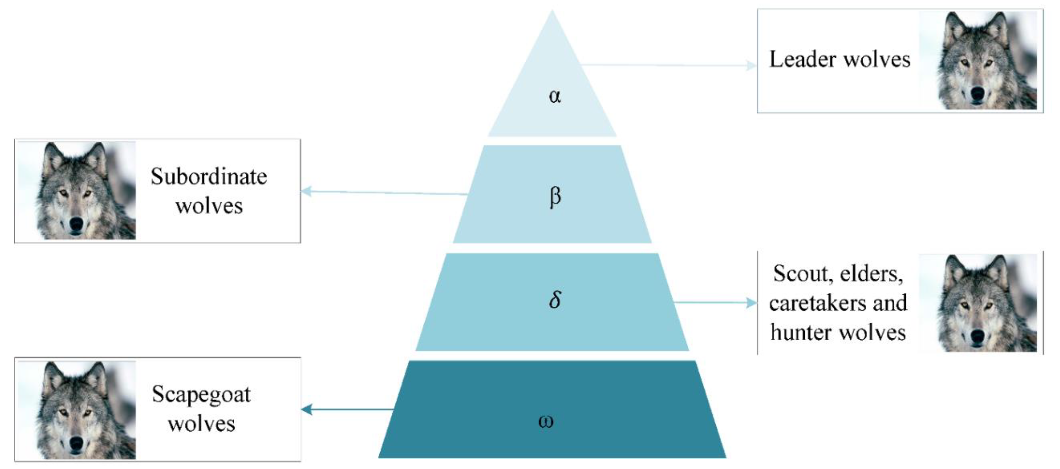
Figure 2.
The proposed GWO algorithm optimizing control parameters for ORPD problem.
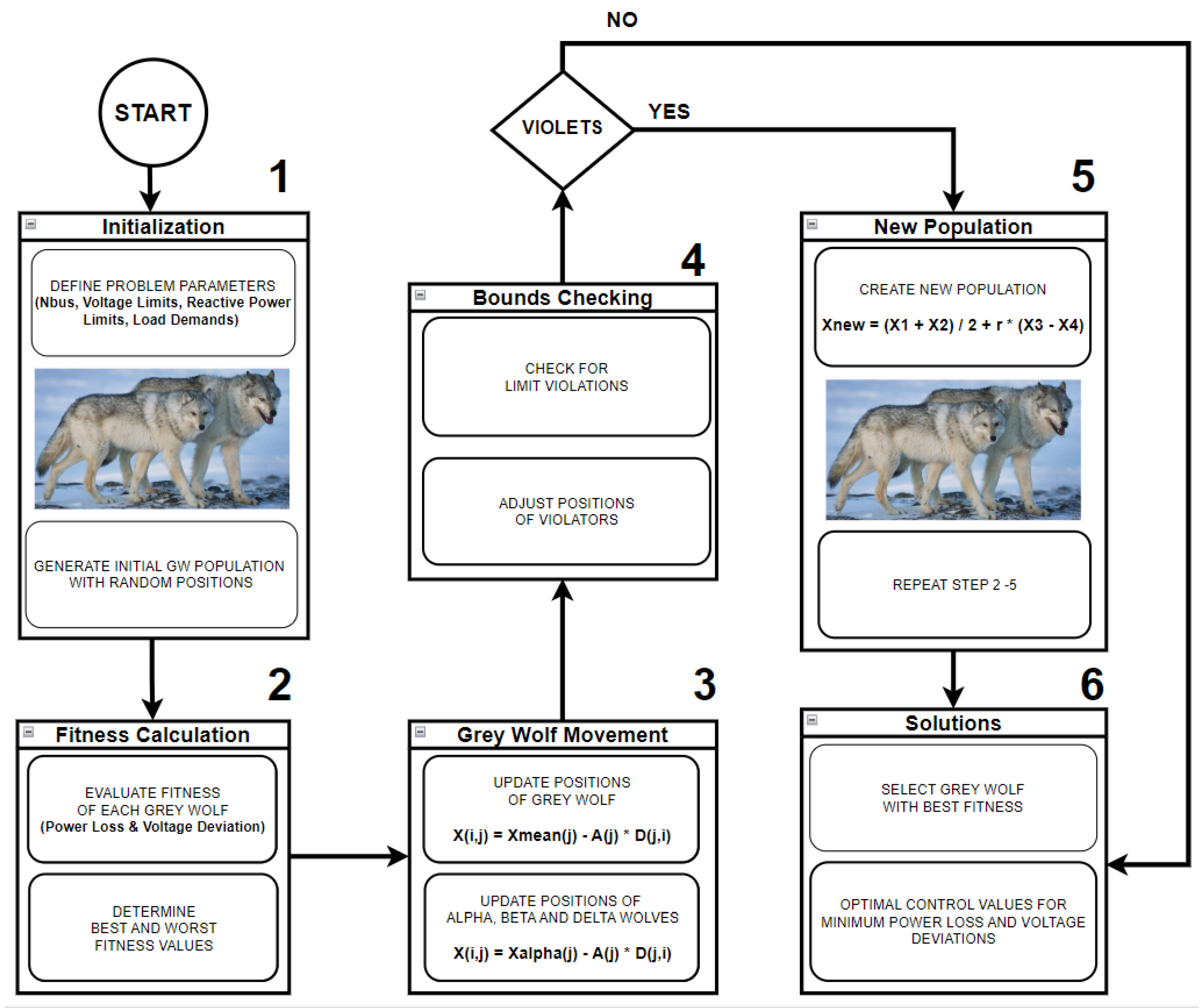
Figure 3.
Convergence patterns for Scenario 1 of the IEEE 30-bus test system.
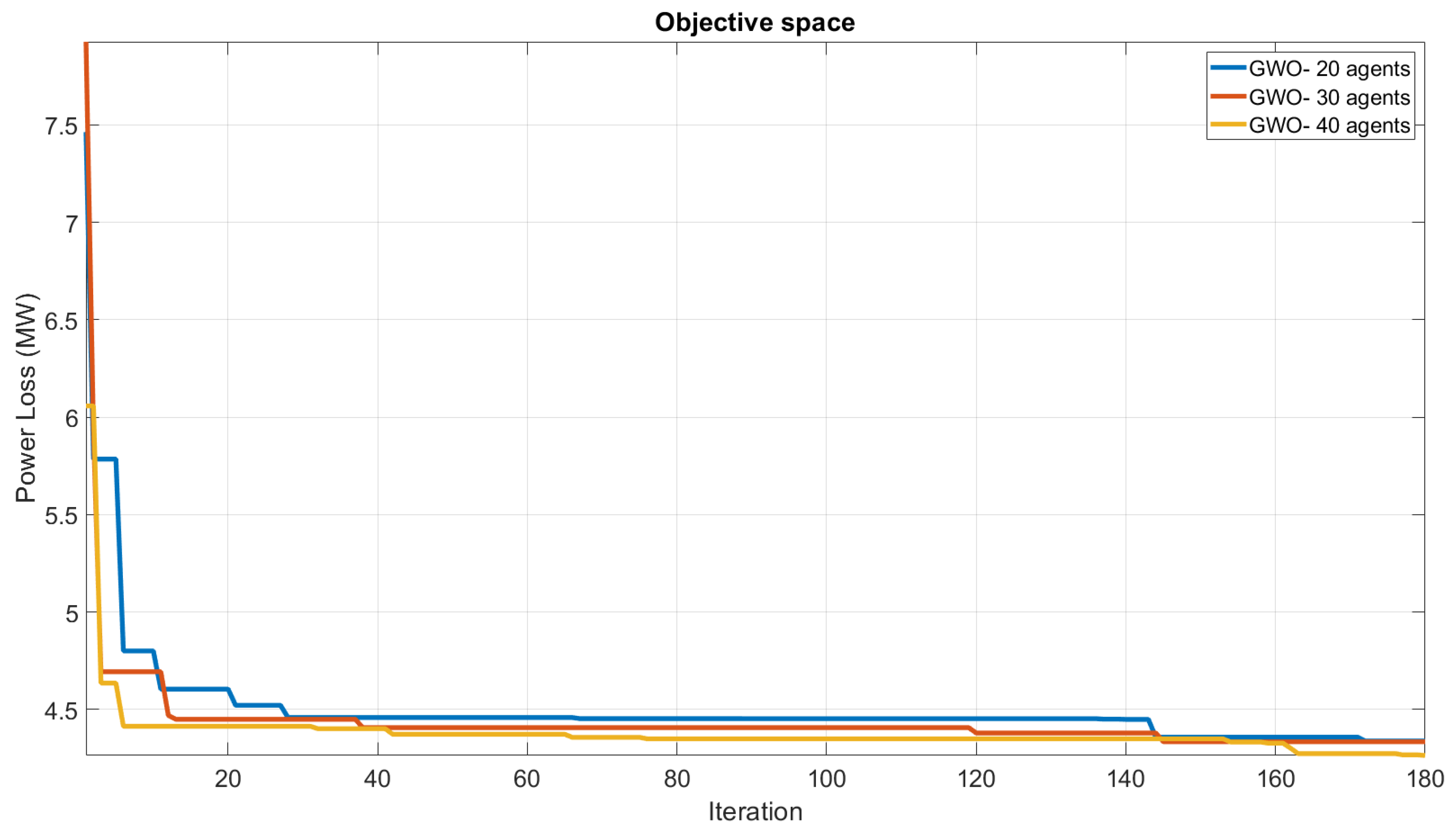
Figure 4.
Convergence patterns for Scenario2 of the IEEE 30-bus test system.
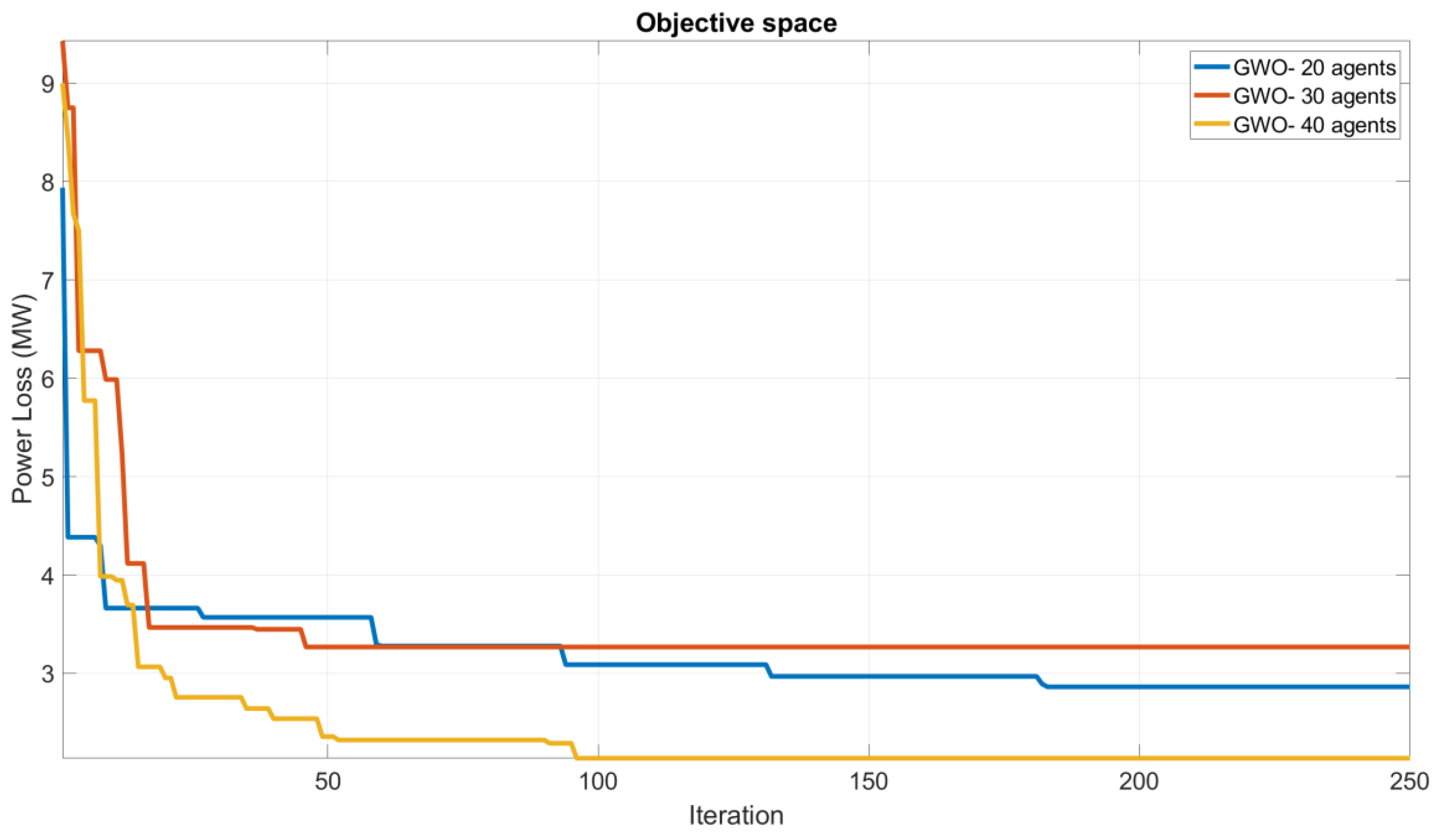
Figure 5.
Voltage deviation convergence patterns for Scenario2 of the IEEE 30-bus test system.
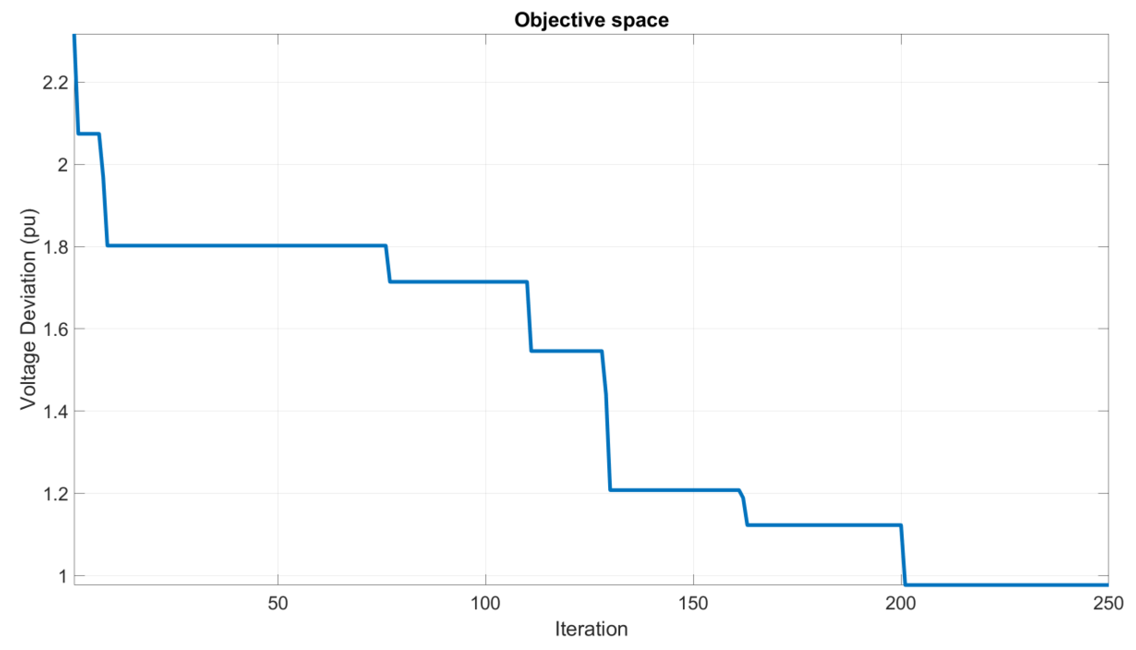
Figure 6.
Convergence patterns for Scenario3 of the IEEE 30-bus test system (wind integration).
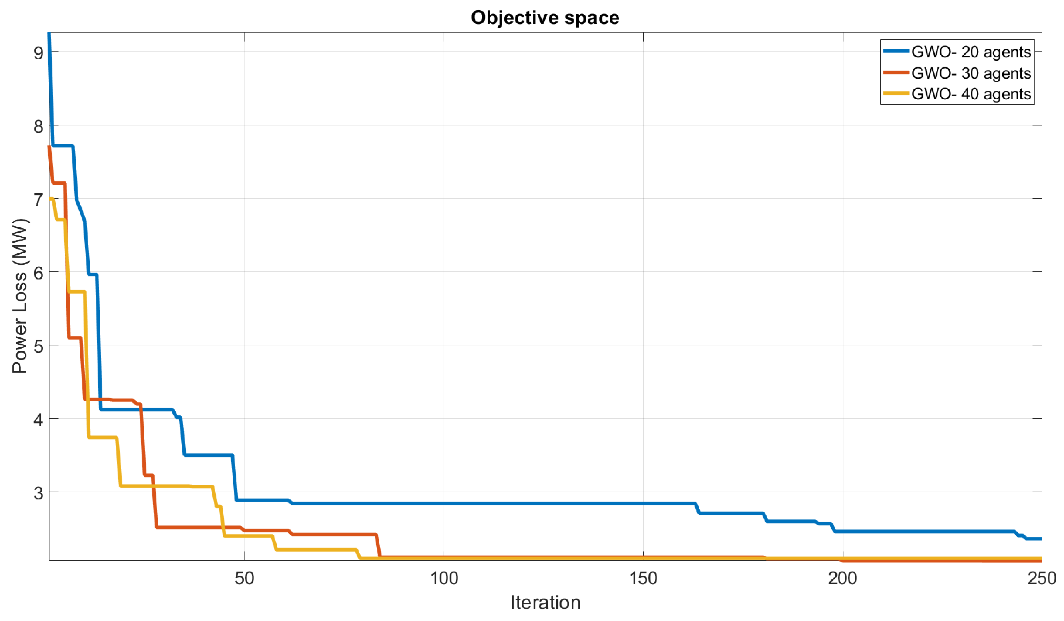
Figure 7.
Voltage deviation convergence patterns for Scenario2 of the IEEE 30-bus system (wind integration).
Figure 7.
Voltage deviation convergence patterns for Scenario2 of the IEEE 30-bus system (wind integration).
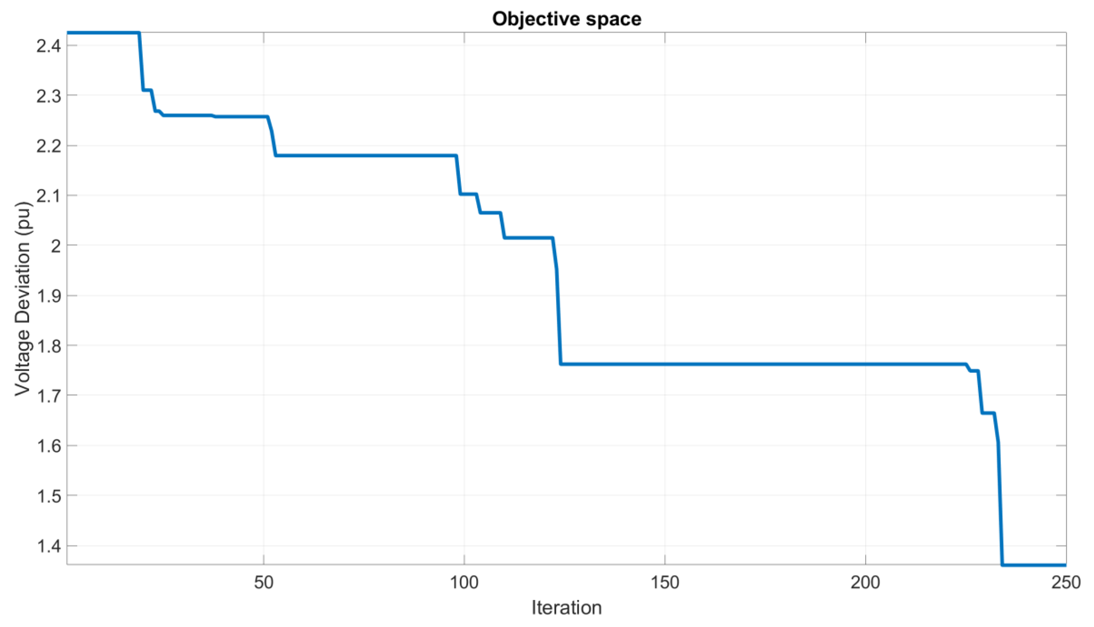
Figure 8.
Power loss convergence patterns for Scenario3 of the IEEE 30-bus system (wind integration).
Figure 8.
Power loss convergence patterns for Scenario3 of the IEEE 30-bus system (wind integration).
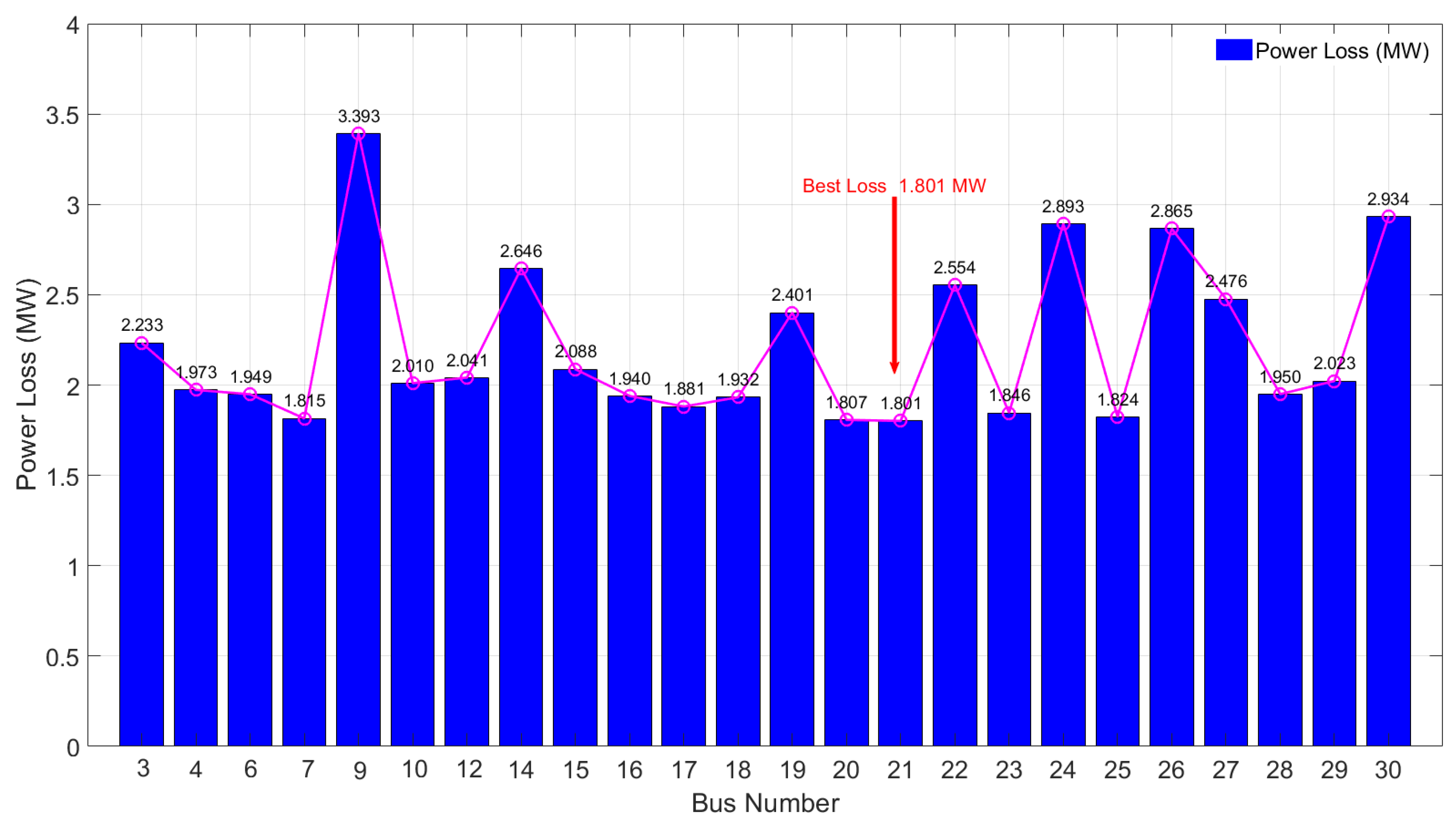
Figure 9.
Convergence patterns for Scenario3 of the IEEE 118-bus test system.
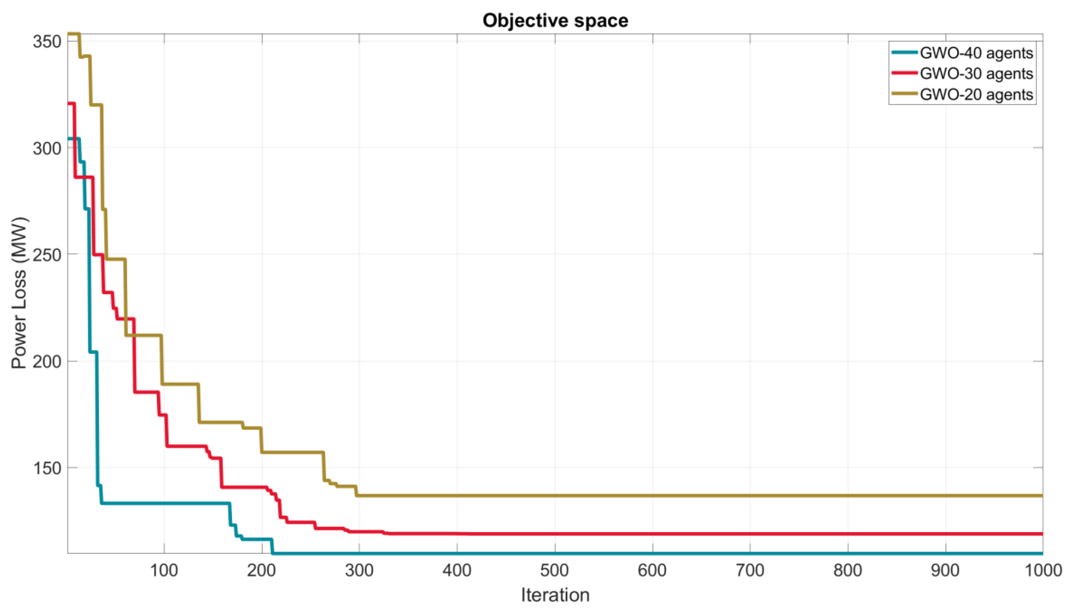
Figure 10.
Voltage deviation convergence patterns for Scenario1 of the IEEE 118-bus system.
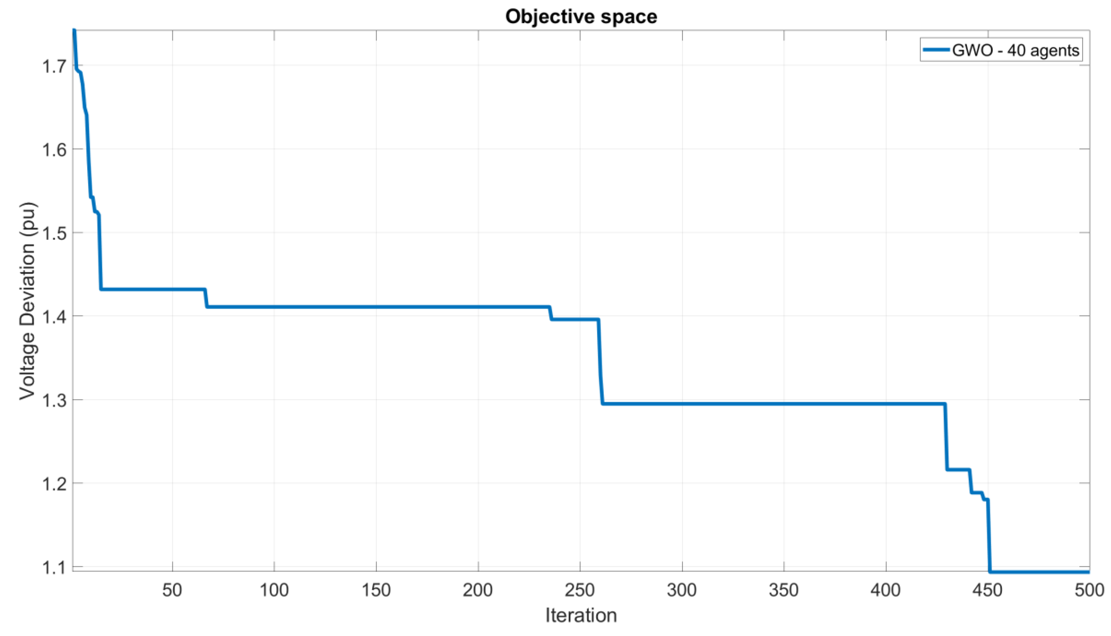
Table 2.
Limit Setting for Control Variables for IEEE-30 System.
| Variables | Lower Limit | Upper Limit |
|---|---|---|
| Voltages | 0.90 pu | 1.10 pu |
| Tap Settings | 0.95 pu | 1.05 pu |
| Compensation Devices | 0 MVAR | 7 MVAR |
Table 3.
Control variables of ORPD for the IEEE 30-bus system in Scenario 1.
| Control Variables | PSO | GA | ABC | GWO (proposed) |
|---|---|---|---|---|
| V1 | 1.1000 | 1.0228 | 1.1000 | 1.1000 |
| V2 | 1.1000 | 1.0181 | 1.0615 | 1.0940 |
| V5 | 1.085 | 0.9859 | 1.0711 | 1.0760 |
| V8 | 1.0838 | 0.9858 | 1.0849 | 1.0837 |
| V11 | 1.1000 | 0.9859 | 1.1000 | 1.0847 |
| V13 | 1.1000 | 0.9815 | 1.0665 | 1.0894 |
| T11 | 1.1000 | 0.9996 | 0.9700 | 1.0385 |
| T12 | 0.9000 | 0.9715 | 1.0500 | 0.9753 |
| T15 | 1.0200 | 0.9794 | 0.9900 | 1.0346 |
| T36 | 0.9900 | 0.9477 | 0.9900 | 1.0016 |
| QC10 | 1.1000 | 2.0124 | 5.0000 | 1.3636 |
| QC12 | 0.4000 | 6.1953 | 5.0000 | 0.6031 |
| QC15 | 0.7000 | 3.4021 | 5.0000 | 2.5714 |
| QC17 | 5.0000 | 1.6718 | 5.0000 | 2.2171 |
| QC20 | 4.7000 | 2.4060 | 4.1000 | 1.3145 |
| QC21 | 1.0000 | 4.0786 | 3.3000 | 4.4976 |
| QC23 | 3.0000 | 2.9779 | 0.9000 | 1.7628 |
| QC24 | 0.8000 | 1.0617 | 5.0000 | 4.4368 |
| QC29 | 1.2000 | 3.1220 | 2.4000 | 1.3185 |
| Total Loss (MW) | 4.66091 | 5.0977 | 4.6022 | 4.1781 |
| Voltage Deviation (pu) | 1.4600 | 0.4773 | 0.7378 | 0.4697 |
Table 4.
Limit Setting for Control Variables for IEEE-30 System.
| Variables | Lower Limit | Upper Limit |
|---|---|---|
| Generated Power | 0.05 pu | 2.00 pu |
| Voltages | 1.00 pu | 1.10 pu |
| Tap Settings | 0.90 pu | 1.10 pu |
| Compensation Devices | 0 MVAR | 5 MVAR |
Table 5.
Control variables of ORPD for the IEEE 30-bus system in Scenario 2.
| Control Variables | Limits | ABC | GWO (proposed) | |
|---|---|---|---|---|
| Lower | Upper | |||
| P1 | 0.50 | 2.00 | 0.5462 | 0.2351 |
| P2 | 0.20 | 0.80 | 0.7863 | 0.4848 |
| P5 | 0.15 | 0.50 | 0.4903 | 0.4700 |
| P8 | 0.10 | 0.50 | 0.3477 | 0.4688 |
| P11 | 0.10 | 0.50 | 0.2999 | 0.4693 |
| P13 | 0.12 | 0.50 | 0.3945 | 0.4617 |
| V1 | 1.00 | 1.10 | 1.0927 | 1.1000 |
| V2 | 1.00 | 1.10 | 1.0880 | 1.0984 |
| V5 | 1.00 | 1.10 | 1.0695 | 1.0805 |
| V8 | 1.00 | 1.10 | 1.0722 | 1.0982 |
| V11 | 1.00 | 1.10 | 1.0860 | 1.0969 |
| V13 | 1.00 | 1.10 | 1.0926 | 1.1000 |
| T11 | 0.90 | 1.10 | 0.9983 | 1.0220 |
| T12 | 0.90 | 1.10 | 0.9994 | 0.9571 |
| T15 | 0.90 | 1.10 | 0.9984 | 1.0386 |
| T36 | 0.90 | 1.10 | 1.0034 | 1.0093 |
| QC10 | 0.00 | 5.00 | 1.5500 | 2.5770 |
| QC12 | 0.00 | 5.00 | 3.9400 | 2.5370 |
| QC15 | 0.00 | 5.00 | 3.4700 | 1.0370 |
| QC17 | 0.00 | 5.00 | 3.3310 | 1.8280 |
| QC20 | 0.00 | 5.00 | 3.3320 | 3.0675 |
| QC21 | 0.00 | 5.00 | 3.9500 | 1.6370 |
| QC23 | 0.00 | 5.00 | 1.3000 | 1.7702 |
| QC24 | 0.00 | 5.00 | 3.7100 | 3.3960 |
| QC29 | 0.00 | 5.00 | 3.9900 | 0.8000 |
| Total Loss (MW) | 3.0410 | 2.0679 | ||
| Voltage Deviation (pu) | 1.0353 | 0.9769 | ||
Table 6.
Limit Setting for Control Variables for IEEE-30 System.
| Variables | Lower Limit | Upper Limit |
|---|---|---|
| Wind Power | 0.00 pu | 0.10 pu |
| Generated Power | 0.05 pu | 2.00 pu |
| Voltages | 1.00 pu | 1.10 pu |
| Tap Settings | 0.90 pu | 1.10 pu |
| Compensation Devices | 0 MVAR | 5 MVAR |
Table 7.
Control variables of ORPD for the IEEE 30-bus system in Scenario 3 (wind integration).
| Control Variables | Limits | GWO (proposed) | |
|---|---|---|---|
| Lower | Upper | ||
| Pwind | 0.00 | 0.10 | 0.0982 |
| P1 | 0.50 | 1.00 | 0.2351 |
| P2 | 0.20 | 0.80 | 0.4848 |
| P5 | 0.15 | 0.50 | 0.4700 |
| P8 | 0.10 | 0.50 | 0.4688 |
| P11 | 0.10 | 0.50 | 0.4693 |
| P13 | 0.12 | 0.50 | 0.4617 |
| Vwind | 1.00 | 1.10 | 1.0604 |
| V1 | 1.00 | 1.10 | 1.0531 |
| V2 | 1.00 | 1.10 | 1.0436 |
| V5 | 1.00 | 1.10 | 1.0500 |
| V8 | 1.00 | 1.10 | 1.0977 |
| V11 | 1.00 | 1.10 | 1.0473 |
| V13 | 1.00 | 1.10 | 0.9781 |
| T11 | 0.90 | 1.10 | 0.9500 |
| T12 | 0.90 | 1.10 | 1.0500 |
| T15 | 0.90 | 1.10 | 1.0343 |
| T36 | 0.90 | 1.10 | 0.9884 |
| QC10 | 0.00 | 5.00 | 4.9322 |
| QC12 | 0.00 | 5.00 | 4.3456 |
| QC15 | 0.00 | 5.00 | 0.7096 |
| QC17 | 0.00 | 5.00 | 2.2971 |
| QC20 | 0.00 | 5.00 | 1.6113 |
| QC21 | 0.00 | 5.00 | 3.0152 |
| QC23 | 0.00 | 5.00 | 0.3921 |
| QC24 | 0.00 | 5.00 | 2.2213 |
| QC29 | 0.00 | 5.00 | 0.4657 |
| Total Loss (MW) | 1.8010 | ||
| Voltage Deviation (pu) | 1.0154 | ||
Table 8.
Limit Setting for Control Variables for IEEE-118 System in Scenario 1.
| Variables | Lower Limit | Upper Limit |
|---|---|---|
| Voltages | 0.95 pu | 1.10 pu |
| Tap Settings | 0.90 pu | 1.10 pu |
| Compensation Devices | -20 MVAR | 20 MVAR |
Table 9.
Control variables of ORPD for the IEEE 118-bus system in Scenario 1.
| Control Variables |
ABC | PSO | GSA | GWO | Control Variables |
ABC | PSO | GSA | GWO |
|---|---|---|---|---|---|---|---|---|---|
| V1 | 1.0512 | 1.0600 | 0.9600 | 0.9903 | V90 | 1.0210 | 0.9905 | 1.0417 | 1.0522 |
| V4 | 1.0757 | 0.9400 | 0.9620 | 1.0094 | V91 | 1.0172 | 1.0015 | 1.0032 | 1.0251 |
| V6 | 1.0791 | 0.9514 | 0.9729 | 1.0208 | V92 | 1.0914 | 1.0600 | 1.0927 | 1.0385 |
| V8 | 1.0656 | 0.9820 | 1.0570 | 0.9697 | V99 | 1.0598 | 0.9938 | 1.0433 | 1.0064 |
| V10 | 1.0461 | 0.9522 | 1.0885 | 1.0721 | V100 | 1.0535 | 1.0264 | 1.0786 | 1.0486 |
| V12 | 1.0726 | 1.0564 | 0.9630 | 1.0095 | V103 | 1.0394 | 0.9400 | 1.0266 | 1.0647 |
| V15 | 1.0265 | 0.9560 | 1.0127 | 0.9764 | V104 | 1.0215 | 1.0600 | 0.9808 | 1.0247 |
| V18 | 1.0314 | 0.9400 | 1.0069 | 0.9616 | V105 | 1 1.10 | 1.0600 | 1.0163 | 1.0329 |
| V19 | 1.0155 | 0.9400 | 1.0003 | 0.9672 | V107 | 1.0463 | 1.0086 | 0.9987 | 1.0469 |
| V24 | 1.0201 | 0.9400 | 1.0105 | 1.0412 | V110 | 1 1.03 | 0.9914 | 1.0218 | 1.0298 |
| V25 | 1.0489 | 0.9884 | 1.0102 | 1.0950 | V111 | 1.0888 | 0.9430 | 0.9852 | 1.0179 |
| V26 | 1.0539 | 0.9930 | 1.0401 | 0.9682 | V112 | 1.0636 | 0.9741 | 0.9500 | 1.0090 |
| V27 | 1.0204 | 0.9670 | 0.9809 | 1.0098 | V113 | 1.0588 | 0.9615 | 0.9764 | 1.0594 |
| V31 | 1.0392 | 0.9400 | 0.9500 | 1.0003 | V116 | 1.0444 | 0.9400 | 1.0372 | 1.0324 |
| V32 | 1.0367 | 1.0030 | 0.9552 | 1.0046 | QC5 | 0 | 20.000 | 0.0000 | 1.0050 |
| V34 | 1.0367 | 0.9400 | 0.9910 | 1.0080 | QC34 | 12.616 | -9.493 | 7.4600 | 0.9954 |
| V36 | 1.0440 | 1.0078 | 1.0091 | 1.0051 | QC37 | 0 | 20.000 | 0.0000 | 1.0284 |
| V40 | 0.9912 | 0.9739 | 0.9505 | 0.9668 | QC44 | 5.3918 | -9.0616 | 6.0700 | 1.0034 |
| V42 | 0.9875 | 0.9450 | 0.9500 | 0.9618 | QC45 | 10 | 20.000 | 3.3300 | 0.9990 |
| V46 | 1.0325 | 1.0392 | 0.9814 | 0.9960 | QC46 | 6.214 | 19.998 | 6.5100 | 1.0447 |
| V49 | 1.0183 | 0.9806 | 1.0444 | 1.0005 | QC48 | 4.9873 | -3.2423 | 4.4700 | 0.9458 |
| V54 | 0.9776 | 1.0600 | 1.0379 | 0.9305 | QC74 | 9.4985 | -17.185 | 9.7200 | 0.9281 |
| V55 | 0.9754 | 0.9736 | 0.9907 | 0.9301 | QC79 | 14.9964 | 3.9148 | 14.250 | 0.9103 |
| V56 | 0.9801 | 0.9715 | 1.0333 | 0.9308 | QC82 | 9.3574 | 19.998 | 17.490 | -26.90 |
| V59 | 1.0235 | 1.0600 | 1.0099 | 0.9495 | QC83 | 3.6167 | 20.000 | 4.2800 | 6.3230 |
| V61 | 1.0400 | 0.9482 | 1.0925 | 0.9700 | QC105 | 17.1048 | -18.989 | 12.040 | -10.63 |
| V62 | 1.0517 | 1.0600 | 1.0393 | 0.9819 | QC107 | 2.0274 | -20.000 | 2.2600 | 3.3801 |
| V65 | 1.0591 | 0.9953 | 0.9998 | 0.9870 | QC110 | 1.8493 | -20.000 | 2.9000 | 4.3057 |
| V66 | 1.0319 | 0.9400 | 1.0355 | 1.0032 | T8 | 1.0768 | 1.0059 | 1.0659 | 8.9977 |
| V69 | 1.0291 | 1.0330 | 1.1000 | 1.0544 | T32 | 0.9655 | 1.1000 | 0.9534 | 5.9038 |
| V70 | 0.9777 | 0.9952 | 1.0992 | 1.0477 | T36 | 1.0601 | 1.0110 | 0.9328 | 4.8237 |
| V72 | 1.0258 | 0.9498 | 1.0014 | 1.0097 | T51 | 1.0081 | 1.0110 | 1.0884 | 4.4373 |
| V73 | 0.9572 | 0.9400 | 1.0111 | 1.0418 | T93 | 1.0509 | 1.0001 | 1.0579 | 13.274 |
| V74 | 0.9691 | 0.9400 | 1.0476 | 1.0073 | T95 | 1.0283 | 1.0155 | 0.9493 | 6.1881 |
| V76 | 0.9908 | 0.9400 | 1.0211 | 1.0212 | T102 | 0.9962 | 1.1000 | 0.9975 | 5.5461 |
| V77 | 1.0209 | 0.9935 | 1.0187 | 1.0410 | T107 | 0.9356 | 0.9243 | 0.9887 | 4.3820 |
| V80 | 1.0542 | 0.9400 | 1.0462 | 1.0476 | T127 | 0.9541 | 0.9589 | 0.9801 | 2.3813 |
| V85 | 1.0121 | 0.9887 | 1.0491 | 1.0604 | |||||
| V87 | 1.0120 | 0.9642 | 1.0426 | 0.9390 | Loss (MW) | 136.99 | 131.897 | 127.760 | 109.744 |
| V89 | 1.0067 | 1.0026 | 1.0955 | 1.0984 |
Table 11.
Control variables of ORPD for the IEEE 118-bus system in Scenario 2.
| Control variables | GWO | Control variables | GWO | Control variables | GWO | Control variables | GWO | Control variables | GWO |
|---|---|---|---|---|---|---|---|---|---|
| P1 | 86.454 | P65 | 46.411 | V1 | 1.0590 | V65 | 1.0689 | QC5 | -15.149 |
| P4 | 56.449 | P66 | 40.835 | V4 | 0.9808 | V66 | 1.0044 | QC34 | 6.0664 |
| P6 | 58.338 | P69 | 37.066 | V6 | 1.0001 | V69 | 1.0790 | QC37 | -3.6222 |
| P8 | 50.098 | P70 | 125.69 | V8 | 0.9932 | V70 | 1.0398 | QC44 | 6.6938 |
| P10 | 34.288 | P72 | 74.627 | V10 | 1.0160 | V72 | 1.0040 | QC45 | 4.4421 |
| P12 | 69.599 | P73 | 63.114 | V12 | 1.0024 | V73 | 1.1000 | QC46 | 1.2265 |
| P15 | 147.08 | P74 | 54.139 | V15 | 1.0183 | V74 | 1.0660 | QC48 | 6.4032 |
| P18 | 91.052 | P76 | 57.223 | V18 | 1.0410 | V76 | 1.0925 | QC74 | 8.2857 |
| P19 | 51.930 | P77 | 27.555 | V19 | 1.0120 | V77 | 1.0836 | QC79 | 8.5603 |
| P24 | 58.426 | P80 | 285.23 | V24 | 1.0254 | V80 | 1.0320 | QC82 | 9.7719 |
| P25 | 73.794 | P85 | 57.696 | V25 | 0.9639 | V85 | 0.9783 | QC83 | 6.8119 |
| P26 | 40.294 | P87 | 72.549 | V26 | 1.0588 | V87 | 1.0465 | QC105 | 5.8368 |
| P27 | 217.58 | P89 | 46.538 | V27 | 1.0296 | V89 | 1.0653 | QC107 | 3.3788 |
| P31 | 36.545 | P90 | 63.959 | V31 | 1.0336 | V90 | 1.0177 | QC110 | 2.9052 |
| P32 | 63.325 | P91 | 54.807 | V32 | 1.0341 | V91 | 1.0518 | T8 | 0.9381 |
| P34 | 21.061 | P92 | 244.41 | V34 | 1.0187 | V92 | 1.0812 | T32 | 0.9463 |
| P36 | 66.161 | P99 | 32.159 | V36 | 1.0075 | V99 | 0.9812 | T36 | 0.9854 |
| P40 | 23.633 | P100 | 44.170 | V40 | 0.9910 | V100 | 1.0375 | T51 | 1.0402 |
| P42 | 161.63 | P103 | 55.985 | V42 | 1.0219 | V103 | 1.0576 | T93 | 1.0500 |
| P46 | 75.908 | P104 | 56.302 | V46 | 1.0768 | V104 | 0.9716 | T95 | 0.9112 |
| P49 | 16.549 | P105 | 34.894 | V49 | 1.0336 | V105 | 0.9981 | T102 | 1.0005 |
| P54 | 64.019 | P107 | 140.97 | V54 | 1.1000 | V107 | 0.9591 | T107 | 0.9756 |
| P55 | 80.821 | P110 | 53.026 | V55 | 1.0706 | V110 | 1.0584 | T127 | 0.9471 |
| P56 | 14.430 | P111 | 36.054 | V56 | 1.0535 | V111 | 1.0359 | Loss (MW) | 68.1578 |
| P59 | 306.06 | P112 | 89.350 | V59 | 1.0948 | V112 | 1.0850 | ||
| P61 | 81.501 | P113 | 58.478 | V61 | 1.0169 | V113 | 1.0399 | ||
| P62 | 67.121 | P116 | 34.454 | V62 | 0.9881 | V116 | 1.0311 |
Table 12.
Limit Setting for Control Variables for IEEE-118 System in Scenario 3.
| Variables | Lower Limit | Upper Limit | |||||||
|---|---|---|---|---|---|---|---|---|---|
| Wind Power | 0.10 pu | 0.50 pu | |||||||
| Generated Power | 0.05 pu | 3.60 pu | |||||||
| Voltages | 1.00 pu | 1.10 pu | |||||||
| Tap Settings | 0.90 pu | 1.10 pu | |||||||
| Compensation Devices | -20 MVAR | 20 MVAR | |||||||
| P62 | 30.217 | V62 | 1.0535 | ||||||
Table 13.
Control variables of ORPD for the IEEE 118-bus system in Scenario 3.
| Control variables | GWO | Control variables | GWO | Control variables | GWO | Control variables | GWO | Control variables | GWO |
|---|---|---|---|---|---|---|---|---|---|
| P1 | 252.23 | P65 | 35.039 | V1 | 1.0424 | V65 | 1.0343 | QC5 | -4.279 |
| P4 | 122.96 | P66 | 37.903 | V4 | 1.0284 | V66 | 1.0629 | QC34 | 8.7954 |
| P6 | 40.162 | P69 | 59.278 | V6 | 1.0134 | V69 | 1.0677 | QC37 | -2.750 |
| P8 | 18.208 | P70 | 82.197 | V8 | 1.0507 | V70 | 1.0668 | QC44 | 1.0647 |
| P9wind | 27.538 | P72 | 93.435 | V9wind | 0.9688 | V72 | 1.0531 | QC45 | 2.4947 |
| P10 | 9.5797 | P73 | 45.600 | V10 | 1.0686 | V73 | 1.0797 | QC46 | 8.2764 |
| P12 | 51.614 | P74 | 11.502 | V12 | 1.0184 | V74 | 1.0450 | QC48 | 3.6636 |
| P15 | 154.29 | P76 | 64.795 | V15 | 1.0011 | V76 | 1.0526 | QC74 | 11.943 |
| P18 | 26.439 | P77 | 40.345 | V18 | 0.9781 | V77 | 1.0475 | QC79 | 8.7899 |
| P19 | 29.869 | P80 | 290.65 | V19 | 0.9890 | V80 | 1.0553 | QC82 | 7.0112 |
| P24 | 28.433 | P85 | 29.615 | V24 | 1.0309 | V85 | 1.0052 | QC83 | 3.2327 |
| P25 | 52.128 | P87 | 40.991 | V25 | 0.9719 | V87 | 1.0538 | QC105 | 2.9738 |
| P26 | 36.567 | P89 | 50.678 | V26 | 1.0583 | V89 | 1.0225 | QC107 | 3.6681 |
| P27 | 115.63 | P90 | 28.770 | V27 | 0.9903 | V90 | 1.0135 | QC110 | 4.0839 |
| P31 | 13.306 | P91 | 31.469 | V31 | 0.9833 | V91 | 1.0254 | T8 | 1.0291 |
| P32 | 88.117 | P92 | 198.11 | V32 | 0.9888 | V92 | 1.0429 | T32 | 0.9981 |
| P34 | 42.177 | P99 | 42.745 | V34 | 1.0128 | V99 | 1.0509 | T36 | 0.9835 |
| P36 | 32.487 | P100 | 62.002 | V36 | 1.0148 | V100 | 1.0417 | T51 | 1.0279 |
| P40 | 40.382 | P103 | 50.258 | V40 | 1.0022 | V103 | 1.0288 | T93 | 0.9752 |
| P42 | 164.87 | P104 | 92.620 | V42 | 1.0152 | V104 | 1.0373 | T95 | 1.0192 |
| P46 | 119.43 | P105 | 27.045 | V46 | 1.0687 | V105 | 1.0403 | T102 | 0.9224 |
| P49 | 24.695 | P107 | 148.33 | V49 | 1.0536 | V107 | 1.0531 | T107 | 0.9590 |
| P54 | 9.7571 | P110 | 50.260 | V54 | 1.0508 | V110 | 1.0197 | T127 | 0.9192 |
| P55 | 50.429 | P111 | 33.580 | V55 | 1.0556 | V111 | 1.0344 | Loss (MW) | 28.1372 |
| P56 | 53.080 | P112 | 17.323 | V56 | 1.0523 | V112 | 0.9949 | ||
| P59 | 327.36 | P113 | 27.363 | V59 | 1.0730 | V113 | 0.9985 | Voltage Deviation (pu) | 1.12945 |
| P61 | 138.60 | P116 | 47.297 | V61 | 1.0522 | V116 | 1.0307 |
Disclaimer/Publisher’s Note: The statements, opinions and data contained in all publications are solely those of the individual author(s) and contributor(s) and not of MDPI and/or the editor(s). MDPI and/or the editor(s) disclaim responsibility for any injury to people or property resulting from any ideas, methods, instructions or products referred to in the content. |
© 2023 by the authors. Licensee MDPI, Basel, Switzerland. This article is an open access article distributed under the terms and conditions of the Creative Commons Attribution (CC BY) license (http://creativecommons.org/licenses/by/4.0/).
Copyright: This open access article is published under a Creative Commons CC BY 4.0 license, which permit the free download, distribution, and reuse, provided that the author and preprint are cited in any reuse.


