Submitted:
12 May 2023
Posted:
15 May 2023
Read the latest preprint version here
Abstract
Polymerase chain reaction (PCR) technique is one of the molecular methods in amplifying DNA for the detection of malaria. However, the limitations of PCR especially when used for routine clinical practice can hamper its sensitivity and specificity. With that, this study focuses on designing a microfluidic device that will mimic the function of a conventional genus-specific PCR based on 18S rRNA gene to detect malaria parasites (Plasmodium falciparum) at low grade parasitemia. The design was drawn and simulated using ANSYS 14.5 Computational Fluid Dynamics (CFD). The simulation shows that adding loops to the design increases its relative deviation but to a minimal extent as compared to having only a straight path design, which indicates that looping is acceptable in designing a microfluidic device to minimize chip length. Also, increasing the cross-sectional area of the fluid path decreases the efficiency of the design, thus, the design with a relatively smaller cross-sectional area is favored. And lastly, among the three materials utilized, the chip made of polypropylene is the most efficient with a relative deviation of 0.94 as compared to polycarbonate and polydimethylsiloxane which have relative deviations of 2.78 and 1.92, respectively.
Keywords:
polymerase chain reaction (PCR)
; Computational Fluid Dynamics (CFD)
; Plasmodium falciparum
; microfluidic chip design
1. Introduction
Malaria is a disease caused by Plasmodium parasites of different species such as Plasmodium falciparum, Plasmodium vivax, Plasmodium malariae, and Plasmodium ovale. Among these species, Plasmodium falciparum and Plasmodium vivax are the most common and Plasmodium falciparum is the deadliest [1,2,3]. These parasites are transmitted to people through the bites of infected mosquitoes, and malaria is highly widespread in tropical and subtropical countries [4,5,6]. In 2021, based on the World Health Organization [7], an estimated 247 million malaria cases were recorded among the 84 malaria endemic countries, with the African region accounting around 95% of the total cases globally. Aside from that, 13.4 million cases between the years 2019 and 2021 were aggravated by the ramifications brought by the COVID-19 pandemic. Individuals from continuous transmission areas may, after several malaria infections, develop the premonition state which is characterized by an immune response that is able to control the parasitemia but unlikely to purge all the circulating parasites. As a result, those individuals can stay asymptomatic and act as a parasitic reservoir since such infected blood is now able to infect mosquito vectors, and with that, these may reintroduce malaria into other regions [8].
Malaria is commonly diagnosed by microscopic examination using Giemsa-stained TBS which is known as the gold standard method for malaria diagnosis, but this technique is not the best choice for low level parasitemia and for mixed infections [9]. However, in some endemic areas, asymptomatic infections are not usually detectable by microscopic examination [10,11,12]. This limitation impacts malaria control and screening of blood samples. Therefore, there is a need for a rapid and accurate diagnosis for effective treatment and control of malaria. It is necessary to develop diagnostic techniques with a high degree of sensitivity and specificity for detecting malaria among environments with relatively low parasite rates and among individuals who are asymptomatic to such disease. Polymerase chain reaction (PCR) assay is found to be one of the most sensitive and specific methods in the detection of malaria parasites [13]. A study was conducted to optimize a faster and cheaper real-time genus-specific PCR based on 18S rRNA gene to detect malaria parasites at low grade parasitemia leading to a threshold sensitivity of 0.2 parasites per 1 μL [14]. However, the time interval concerning the collection and transportation of samples, and the processing and dissemination of results limit the usefulness of PCR in routine clinical practice. Besides that, in most areas with malaria transmission, factors such as limited financial resources, persistent subclinical parasitemia, and inadequate laboratory infrastructures in the poor, remote rural areas impede PCR as a diagnostic method [15]. These factors reason for the need to create a microfluidic device that is portable, economical, and accessible but still functional like how the conventional PCR is.
This concept of miniaturizing PCR aims to speed up the process of conventional PCR by reducing the overall sample volume and consumption of reagents, lessening the cost of fabrication, and developing a field-based real-time PCR platform that is capable of completely conducting analyses from raw samples into promising results that will ensure a better method of diagnosing malaria. With the growing interest in developing in-field diagnostic devices that could be used by non-technical personnel involved, this study would surely provide the necessary preliminary data of innovating a device that can aid in the prevalence of malaria in the world. Because of that, a real-time PCR-based microfluidics platform that integrates and miniaturizes DNA purification, amplification, and detection is being introduced for in-field detection. The purpose of this study is to design and simulate a microfluidic PCR chip device which can specifically detect Plasmodium falciparum DNA fragment amplification using the software ANSYS 14.5 Computational Fluid Dynamics (CFD). The design is based on the real-time PCR amplification setting for conventional genus-specific PCR targeted on 18S rRNA gene to detect malaria parasites (Plasmodium falciparum). The fluid property used in the simulation is based on the solvent property of water (see S3) [16]. Different types of materials such as polypropylene, polycarbonate, and polydimethylsiloxane were evaluated and certain design considerations such as the effects of looping and increasing the cross-sectional area were analyzed. After simulating various models and conducting the necessary tests, this intends to determine from the results the most appropriate design that will help in pre-selecting the materials and planning the optimum parameters needed to consider before fabricating the microfluidic PCR chip device for actual use.
2. Materials and Methods
The design was based on the DNA amplification procedure for conventional genus- specific PCR whose target is the 18S rRNA gene in detecting malaria parasites (Plasmodium falciparum) at low grade parasitemia. The design requires 25 μL of PCR mix and 5 μL of DNA sample. The total volume of 30 μL then proceeds the annealing, extension, and denaturation processes specified at various temperatures to determine which conditions would the device be most efficient to use (see S1 and S2).

Table 1.
PCR mixture and DNA sample volumes.
| Volume (μL) | |
|---|---|
| PCR Mix | 25 |
| DNA Sample | 5 |
| Total | 30 |
Moreover, three polymers were tested to determine which material best suits the design for fabricating the microfluidic PCR chip. Table 2 lists the thermal properties of the polymeric materials utilized in the design.
The first part of the simulation was intended to determine the effects of looping on the temperature of the fluid inside the device. Aside from that, this also aimed to assess the influence of looping to the efficiency of the design by calculating their respective relative deviation and average square of difference based on a set temperature of 58°C. Three variations were tested: a design with no loops, one loop, and two loops of the same linear path lengths were drawn. The dimensions are shown in Table 3.
The proposed microfluidic PCR chip was modeled using ANSYS 14.5 CFD with the following dimensions shown in Table 4.
The other parameters considered in designing the microfluidic PCR chip are listed in Table 5. Moreover, Figure 1 shows the 44-cycle microfluidic PCR chip and the 2-cycle microfluidic PCR chip utilized in testing the design.
Different polymeric materials such as polypropylene, polycarbonate, and polydimethylsiloxane were used as the microfluidic PCR chip material in the simulation, and the most efficient material was evaluated using relative deviation and average square of difference. After assessing which material is the best choice, the diameter and length of the design were changed to determine the effect of varying the cross-sectional area of the fluid path to the fluid temperature. The dimensions used for this test are listed in Table 6.
3. Results and Discussion
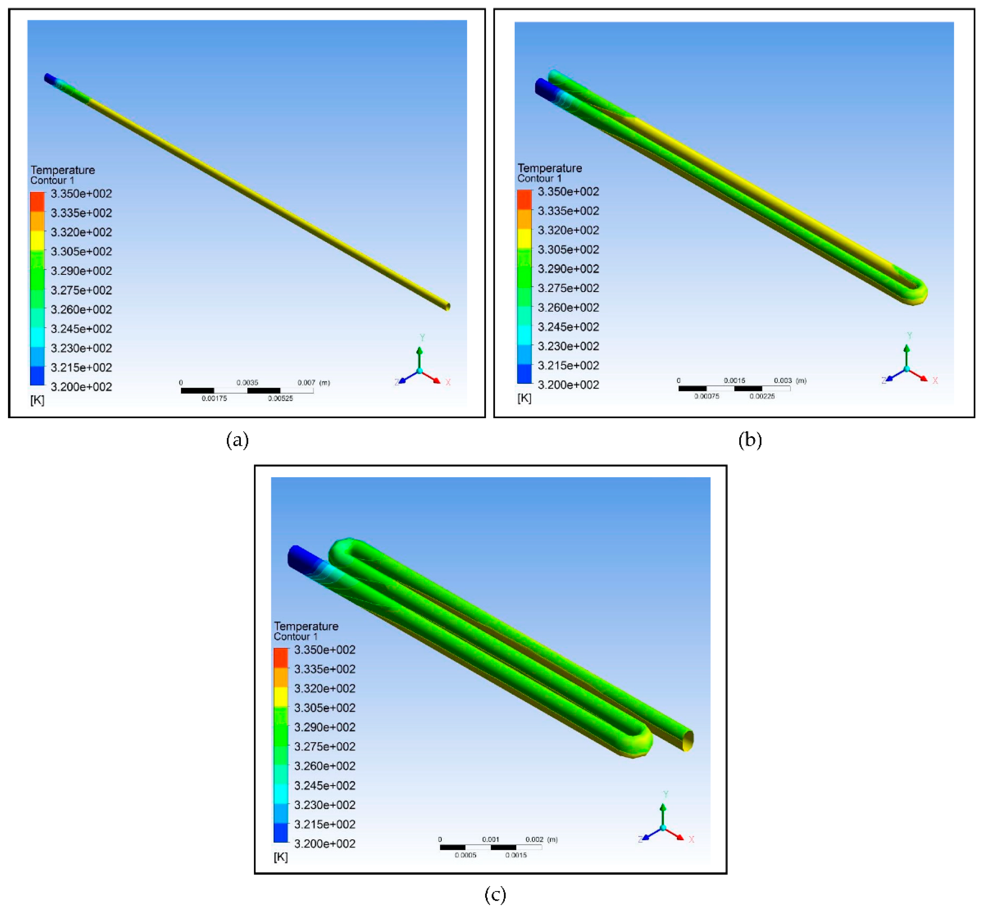
Based on the data listed in Table 3, three designs were modeled with one having no loops, one having only a loop, and one having two loops. The copper plate for all three was set at a temperature of 58°C, and the designs were simulated using ANSYS 14.5 CFD. As shown in Table 7, as the number of loops is increased, the relative deviation also increases which indicates that the efficiency of the design decreases; however, the decrease is not that significant. The simulation shows that a fluid temperature maintained within 58°C, the relative deviation for the design with no loops is 0.65, with one loop is 0.80, and with two loops is 0.88. This decreasing trend is indicative of decreasing efficiency but only to a minimal extent. Therefore, looping can be used in designing the microfluidic PCR chip to reduce the chip length and to increase the residence time of the sample inside the device.
Figure 2.
Using ANSYS 14.5 Computational Fluid Dynamics (CFD), the designs intended to test the effect of looping on the efficiency of the device were modelled: (a) Design with no loops; (b) Design with one loop; (c) Design with two loops.
Figure 2.
Using ANSYS 14.5 Computational Fluid Dynamics (CFD), the designs intended to test the effect of looping on the efficiency of the device were modelled: (a) Design with no loops; (b) Design with one loop; (c) Design with two loops.
For the simulation of the proposed microfluidic PCR chip, the designs drawn using ANSYS 14.5 CFD are shown in Figure 3. The five copper plates seen in Figure 3(b) were set at temperatures 58°C, 72°C, 95°C, 72°C, and 58°C for the first simulation, temperatures 60°C, 74°C, 97°C, 74°C, and 60°C for the second simulation, and temperatures 63°C, 77°C, 100°C, 77°C, and 63°C for the third simulation for each material (the order of temperatures corresponds to the order of plates seen in the figure).
The final design is illustrated in Figure 4, showing a 44-cycle microfluidic PCR chip design.
However, during the meshing procedure on the ANSYS 14.5 CFD, the software cannot mesh the design due to its limitation since the program is only accessible for educational use. Instead of meshing the whole design, only a 2-cycle microfluidic PCR chip design was meshed and simulated as representative of the 44-cycle microfluidic PCR chip design.
Furthermore, different polymeric materials were tested to determine which is the best choice to be used for designing the microfluidic chip. Figure 5 illustrates the simulation of the microfluidic PCR chip designs modelled from polypropylene set at various copper temperatures. Figure 6 illustrates the simulation of the microfluidic PCR chip designs modelled from polycarbonate set at various copper temperatures. And Figure 7 illustrates the simulation of the microfluidic PCR chip designs modelled from polydimethylsiloxane set at various copper temperatures.
Using the data at different nodes generated from the various simulations, the relative deviation and average square of difference (ASD) were calculated as shown in Table 8.
The results show that polypropylene set at a copper plate temperature of 58°C for annealing, 72°C for extension, and 95°C for denaturation has the lowest relative deviation of 0.94 and lowest average square of difference (ΔT2/n) of 3.21. This suggests that polypropylene under this set condition is the most efficient material to use in fabricating the microfluidic PCR chip.
Consequently, after figuring out that polypropylene is the best option, the microfluidic PCR chip with this design set under the optimum temperatures of 58°C, 72°C, and 95°C was subjected to further testing by changing the parameters of the design as based on the dimensions listed in Table 6, while unchanging the inlet velocity of the models. Figure 8 illustrates the results of the simulations, and Table 9 shows the relative deviation and average square of difference (ASD) calculated from the two designs.
The data shows that increasing the diameter and length of the fluid path affects the fluid temperature. Increasing the cross-sectional area using the same inlet velocity of the fluid flowing through the chip also results in the increase of relative deviation and ASD indicating a decrease in efficiency of reaching the set temperature at different zones. Thus, the design using a smaller cross-sectional area is most suitable to use because of its comparatively lower relative deviation and ASD, which predispose it to be favored more in fabricating the device.
Since one of the aims of this study is to reduce the cost of the device for public access, limiting material utilization was necessary in order to compensate for this. Miniaturizing the conventional PCR through fabricating a more portable and relatively smaller device would surely affect its efficiency in detecting Malaria, especially in the amplification process [20]. The proposed microfluidic PCR chip is designed to detect Malaria even with a small sample volume while, at the same time, not compromising the specificity of the test. The threshold cycle of the conventional PCR amplification of P.falciparum DNA fragments is 36 with a threshold sensitivity of 0.2 parasite per 1 μL [21]. However, the proposed microfluidic PCR chip was designed for 44 cycles because it is also intended to detect small samples, which need to be amplified more compared to samples of greater volume. The amount of time it takes for the microfluidic PCR chip to amplify the sample for a given number cycles was evaluated, in which the results are shown in Table 10 (see S3). In 44 cycles, which the device was specifically designed for, consumes around 112.23 minutes to complete the process.
4. Conclusion
The simulation shows that looping can affect the temperature of the fluid to a minimal extent, and therefore, can be considered in designing a microfluidic PCR chip in order to decrease the chip length. Based on the simulation, the best material for designing the microfluidic PCR chip is polypropylene with a relative deviation of 0.94 from the set temperatures of 58°C (annealing), 72°C (extension), and 95°C (denaturation). It was also proven that increasing the cross-sectional area of the fluid path can have an effect on the temperature of the fluid; thus, it is recommended to use a smaller cross-sectional area to ensure that the set temperatures in different zones are reached. With the objectives this simulative study aims to answer, the results generated from this intend to serve as a preliminary screening towards an optimized design of a microfluidic-based PCR device for P. falciparum DNA fragment amplification.
As mentioned earlier, only a 2-cycle microfluidic chip design was meshed due to the limitation of the software. Future researchers might want to take a look at this and try to mesh the 44-cycle microfluidic chip used in this study. Other parameters may be tested as well for their effect on the efficiency of the device in detecting malaria, and other materials may be assessed to broaden the application of this design.
Supplementary Materials
The following supporting information can be downloaded at the website of this paper posted on Preprints.org.
References
- W. Domingues, E.H. dos Santos, L. Yamamoto, S.M. Di Santi, K.A. Kanunfre, T.S. Okay, Single-round multiplex PCR with species-specific mitochondrial primers of P. falciparum, P. vivax/P. simium and P. malariae/P. brasilianum: Comparison with standard techniques, J Microbiol Methods. 193 (2022) 106398. [CrossRef]
- S. Shimizu, S. Chotirat, N. Dokkulab, I. Hongchad, K. Khowsroy, K. Kiattibutr, N. Maneechai, K. Manopwisedjaroen, P. Petchvijit, K. Phumchuea, N. Rachaphaew, P. Sripoorote, C. Suansomjit, W. Thongyod, A. Khamsiriwatchara, S. Lawpoolsri, B. Hanboonkunupakarn, J. Sattabongkot, W. Nguitragool, Malaria cross-sectional surveys identified asymptomatic infections of Plasmodium falciparum, Plasmodium vivax and Plasmodium knowlesi in Surat Thani, a southern province of Thailand, International Journal of Infectious Diseases. 96 (2020) 445–451. [CrossRef]
- M.A. Abdulraheem, M. Ernest, I. Ugwuanyi, H.M. Abkallo, S. Nishikawa, M. Adeleke, A.E. Orimadegun, R. Culleton, High prevalence of Plasmodium malariae and Plasmodium ovale in co-infections with Plasmodium falciparum in asymptomatic malaria parasite carriers in southwestern Nigeria, Int J Parasitol. 52 (2022) 23–33. [CrossRef]
- E. Legendre, L. Lehot, S. Dieng, S. Rebaudet, A.M. Thu, J.D. Rae, G. Delmas, F. Girond, V. Herbreteau, F. Nosten, J. Landier, J. Gaudart, Malaria temporal dynamic clustering for surveillance and intervention planning, Epidemics. 43 (2023) 100682. [CrossRef]
- X. Wang, H. Sun, Metal Complexes in the Treatment of Tropical Diseases: Malaria, Trypanosomiasis, and Leishmaniasis, Comprehensive Inorganic Chemistry II (Second Edition): From Elements to Applications. 3 (2013) 975–986. [CrossRef]
- M.D. Corbacho-Loarte, C. Crespillo-Andújar, S. Chamorro-Tojeiro, F. Norman, J.A. Pérez-Molina, O. Martín, J.M. Rubio, B. Gullón-Peña, R. López-Vélez, B. Monge-Maillo, Screening of imported malaria infection in asymptomatic migrants from Sub-Saharan Africa: A retrospective analysis of a 2010–2019 cohort, Travel Med Infect Dis. 49 (2022) 102411. [CrossRef]
- W.H. Organization, World malaria report 2022, World Health Organization, 2022.
- R.C. Pessoa, G.F. Oliveira-Pessoa, B.K.A. Souza, V.S. Sampaio, A.L.C.B. Pinto, L.L. Barboza, G.S. Mouta, E.L. Silva, G.C. Melo, W.M. Monteiro, J.H. Silva-Filho, M.V.G. Lacerda, D.C. Baía-da-Silva, Impact of Plasmodium vivax malaria on executive and cognitive functions in elderlies in the Brazilian Amazon, Scientific Reports 2022 12:1. 12 (2022) 1–10. [CrossRef]
- D.N. Ofosu, O.S. Benfield, M. Adams, C. Nkrumah, A. Asamoah, M.K. Addai, B.A. Owusu, E. Owusu, Y. Marfo-Debrekyei, W.A. Mills-Pappoe, B. Sackey, Assessing malaria staining practices with Giemsa for malaria microscopy; a case of selected laboratory facilities in the Ashanti region of Ghana, Sci Afr. 16 (2022) e01133. [CrossRef]
- D. Prusty, N. Gupta, A. Upadhyay, A. Dar, B. Naik, N. Kumar, V.K. Prajapati, Asymptomatic malaria infection prevailing risks for human health and malaria elimination, Infection, Genetics and Evolution. 93 (2021) 104987. [CrossRef]
- M.D. Corbacho-Loarte, C. Crespillo-Andújar, S. Chamorro-Tojeiro, F. Norman, J.A. Pérez-Molina, O. Martín, J.M. Rubio, B. Gullón-Peña, R. López-Vélez, B. Monge-Maillo, Screening of imported malaria infection in asymptomatic migrants from Sub-Saharan Africa: A retrospective analysis of a 2010–2019 cohort, Travel Med Infect Dis. 49 (2022) 102411. [CrossRef]
- A.A. Medjigbodo, L. Djossou, C.J. Adoha, O.Y. Djihinto, A. Ogouyemi-Hounto, M.J. Donnelly, D. Weetman, L.S. Djogbénou, Asymptomatic Plasmodium infection among primary schoolchildren and Anopheles-mediated malaria transmission: A cross-sectional study in Ouidah; south-western Benin, Parasite Epidemiol Control. 21 (2023) e00285. [CrossRef]
- P. Berzosa, A. De Lucio, M. Romay-Barja, Z. Herrador, V. González, L. García, A. Fernández-Martínez, M. Santana-Morales, P. Ncogo, B. Valladares, M. Riloha, A. Benito, Comparison of three diagnostic methods (microscopy, RDT, and PCR) for the detection of malaria parasites in representative samples from Equatorial Guinea, Malar J. 17 (2018) 333. [CrossRef]
- D.T. McNamara, L.J. Kasehagen, B.T. Grimberg, J. Cole-Tobian, W.E. Collins, P.A. Zimmerman, DIAGNOSING INFECTION LEVELS OF FOUR HUMAN MALARIA PARASITE SPECIES BY A POLYMERASE CHAIN REACTION/LIGASE DETECTION REACTION FLUORESCENT MICROSPHERE-BASED ASSAY, Am J Trop Med Hyg. 74 (2006) 413. [CrossRef]
- N. Minhas, Y.K. Gurav, S. Sambhare, V. Potdar, M.L. Choudhary, S.D. Bhardwaj, P. Abraham, Cost-analysis of real time RT-PCR test performed for COVID-19 diagnosis at India’s national reference laboratory during the early stages of pandemic mitigation, PLoS One. 18 (2023). [CrossRef]
- X.D. Yang, R.V.N. Melnik, Effect of internal viscosity on Brownian dynamics of DNA molecules in shear flow, Comput Biol Chem. 31 (2007) 110–114. [CrossRef]
- C. Maier, T. Calafut, Polypropylene: The Definitive User’s Guide and Databook, Elsevier Science, 2008. https://books.google.dk/books?id=AWaSJd9Non8C.
- H.E. Bair, D.R. Falcone, M.Y. Hellman, G.E. Johnson, P.G. Kelleher, Hydrolysis of polycarbonate to yield BPA, J Appl Polym Sci. 26 (1981) 1777–1786. [CrossRef]
- B.K. Gale, M.A. Eddings, S.O. Sundberg, A. Hatch, J. Kim, T. Ho, S.M. Karazi, Low-Cost MEMS Technologies, Reference Module in Materials Science and Materials Engineering. (2016). [CrossRef]
- J.A. Huber, H.G. Morrison, S.M. Huse, P.R. Neal, M.L. Sogin, D.B. Mark Welch, Effect of PCR amplicon size on assessments of clone library microbial diversity and community structure, Environ Microbiol. 11 (2009) 1292. [CrossRef]
- N. Hofmann, F. Mwingira, S. Shekalaghe, L.J. Robinson, I. Mueller, I. Felger, Ultra-Sensitive Detection of Plasmodium falciparum by Amplification of Multi-Copy Subtelomeric Targets, PLoS Med. 12 (2015) e1001788. [CrossRef]
Figure 1.
Using ANSYS 14.5 Computational Fluid Dynamics (CFD), the microfluidic PCR chip was modeled to evaluate which design would be best utilized in fabricating the device for actual use. The number of cycles must be specified since this also alters the functionality of the microfluidic PCR chip in detecting malaria. A visual comparison is shown above: (a) 44-cycle microfluidic PCR chip design; (b) 2-cycle microfluidic PCR chip design.
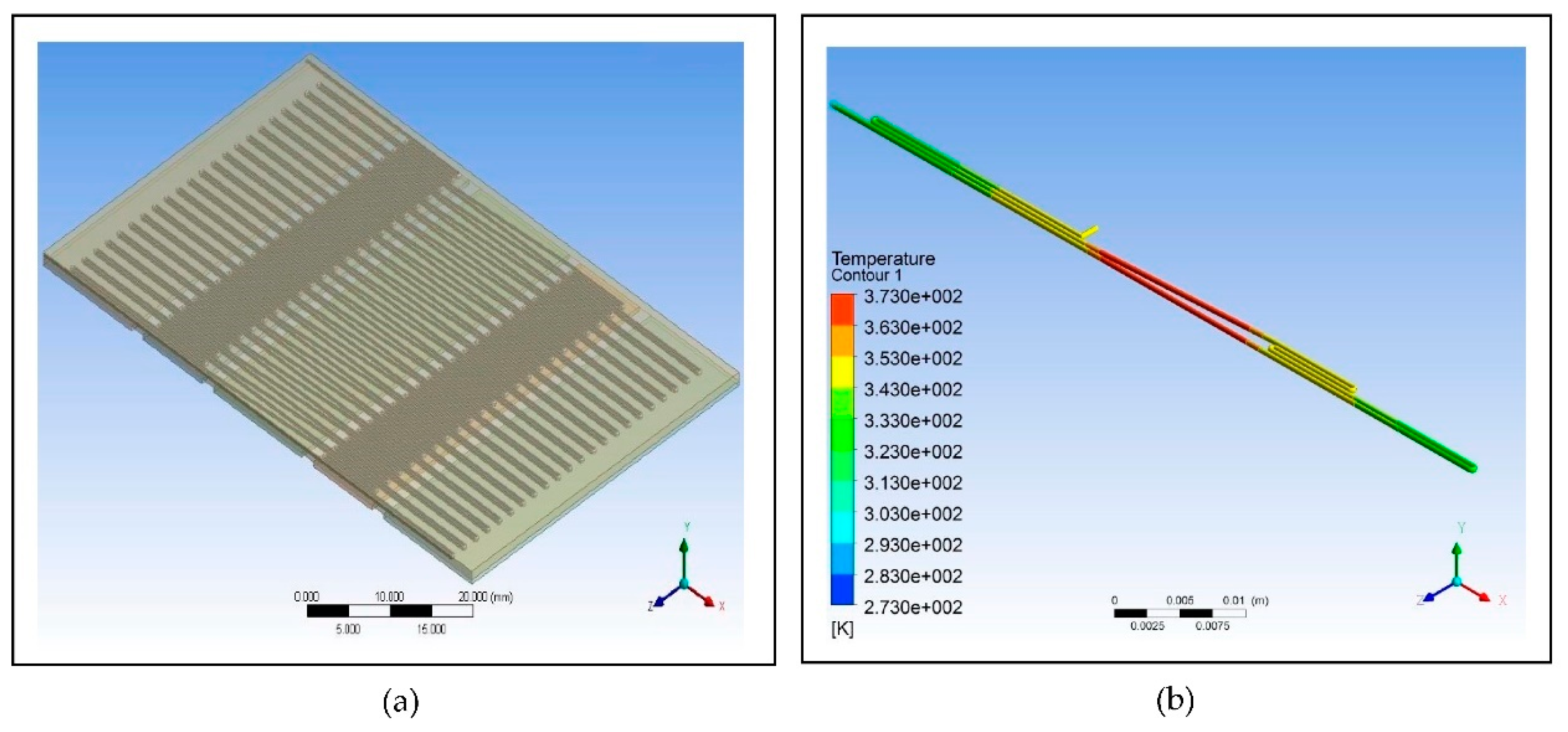
Figure 3.
Images of the proposed microfluidic PCR chip design modelled from ANSYS 14.5 Computational Fluid Dynamics (CFD): (a) Microfluidic chip dimensions; (b) Microfluidic chip side view.
Figure 3.
Images of the proposed microfluidic PCR chip design modelled from ANSYS 14.5 Computational Fluid Dynamics (CFD): (a) Microfluidic chip dimensions; (b) Microfluidic chip side view.
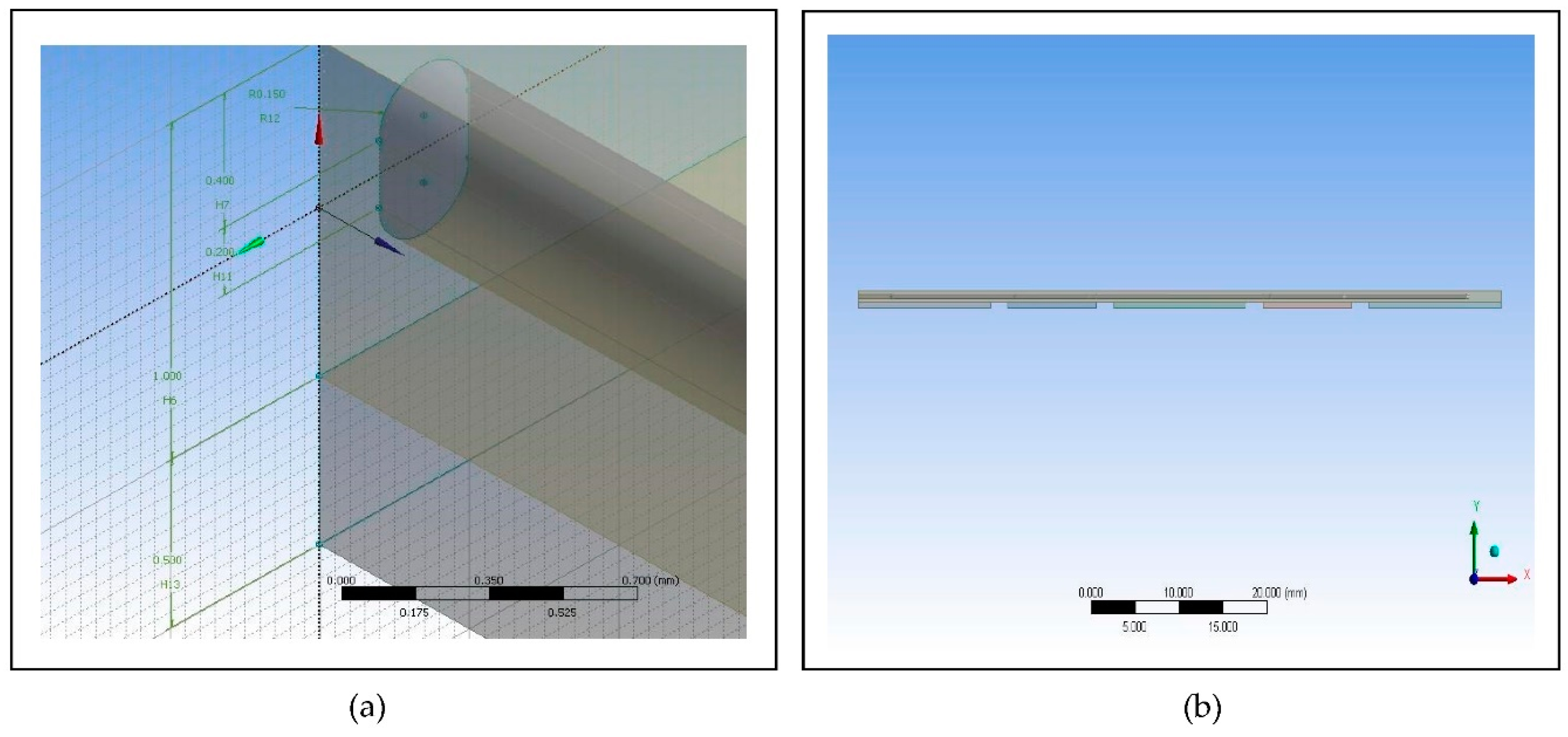
Figure 4.
Image of the 44-cycle microfluidic PCR chip design modelled from ANSYS 14.5 Computational Fluid Dynamics (CFD).
Figure 4.
Image of the 44-cycle microfluidic PCR chip design modelled from ANSYS 14.5 Computational Fluid Dynamics (CFD).
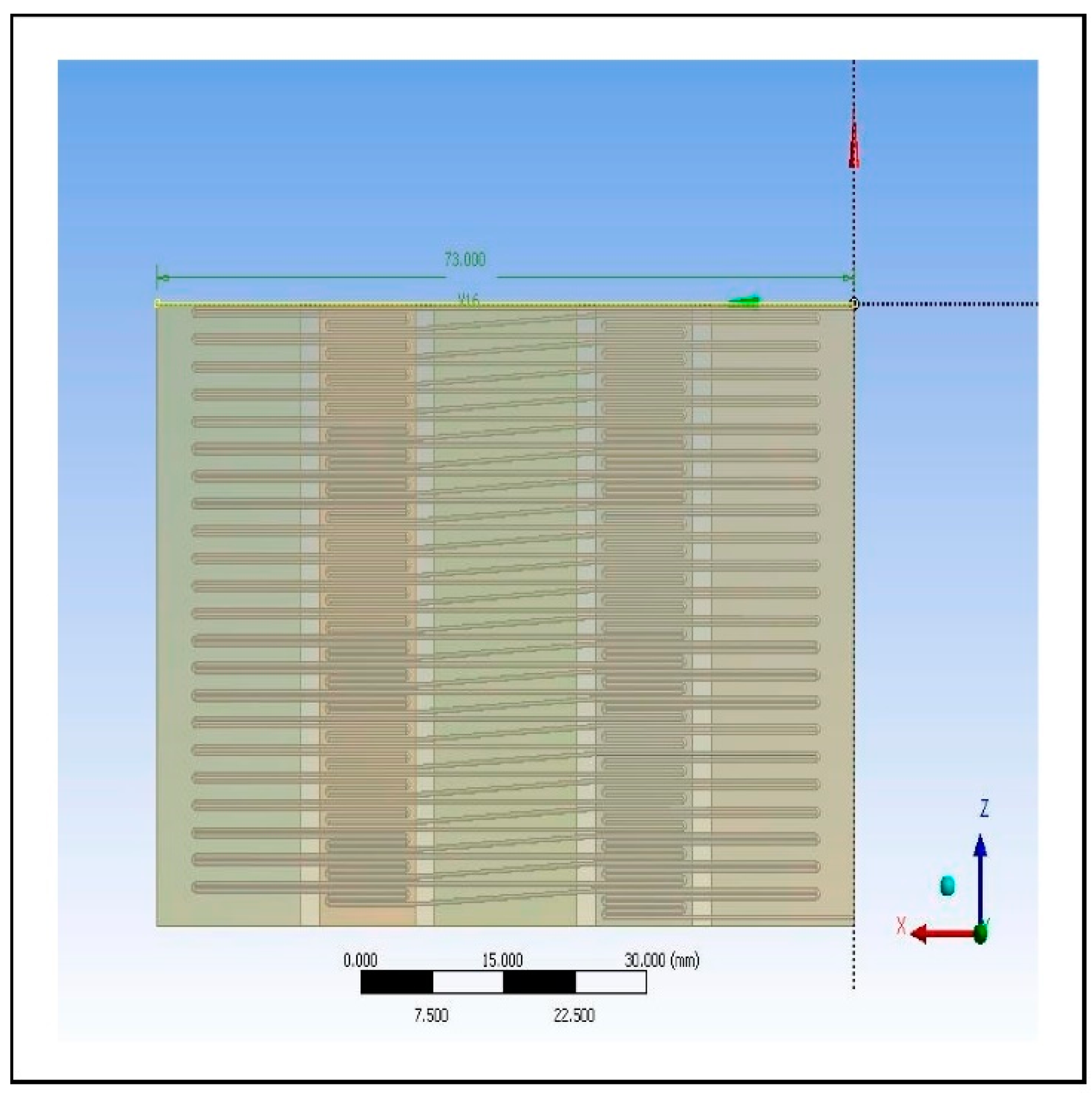
Figure 5.
Polypropylene microfluidic PCR chip design set at temperatures of: (a) 58°C (annealing), 72°C (extension), and 95°C (denaturation); (b) 60°C (annealing), 74°C (extension), and 97°C (denaturation); (c) 63°C (annealing), 77°C (extension), and 100°C (denaturation).
Figure 5.
Polypropylene microfluidic PCR chip design set at temperatures of: (a) 58°C (annealing), 72°C (extension), and 95°C (denaturation); (b) 60°C (annealing), 74°C (extension), and 97°C (denaturation); (c) 63°C (annealing), 77°C (extension), and 100°C (denaturation).
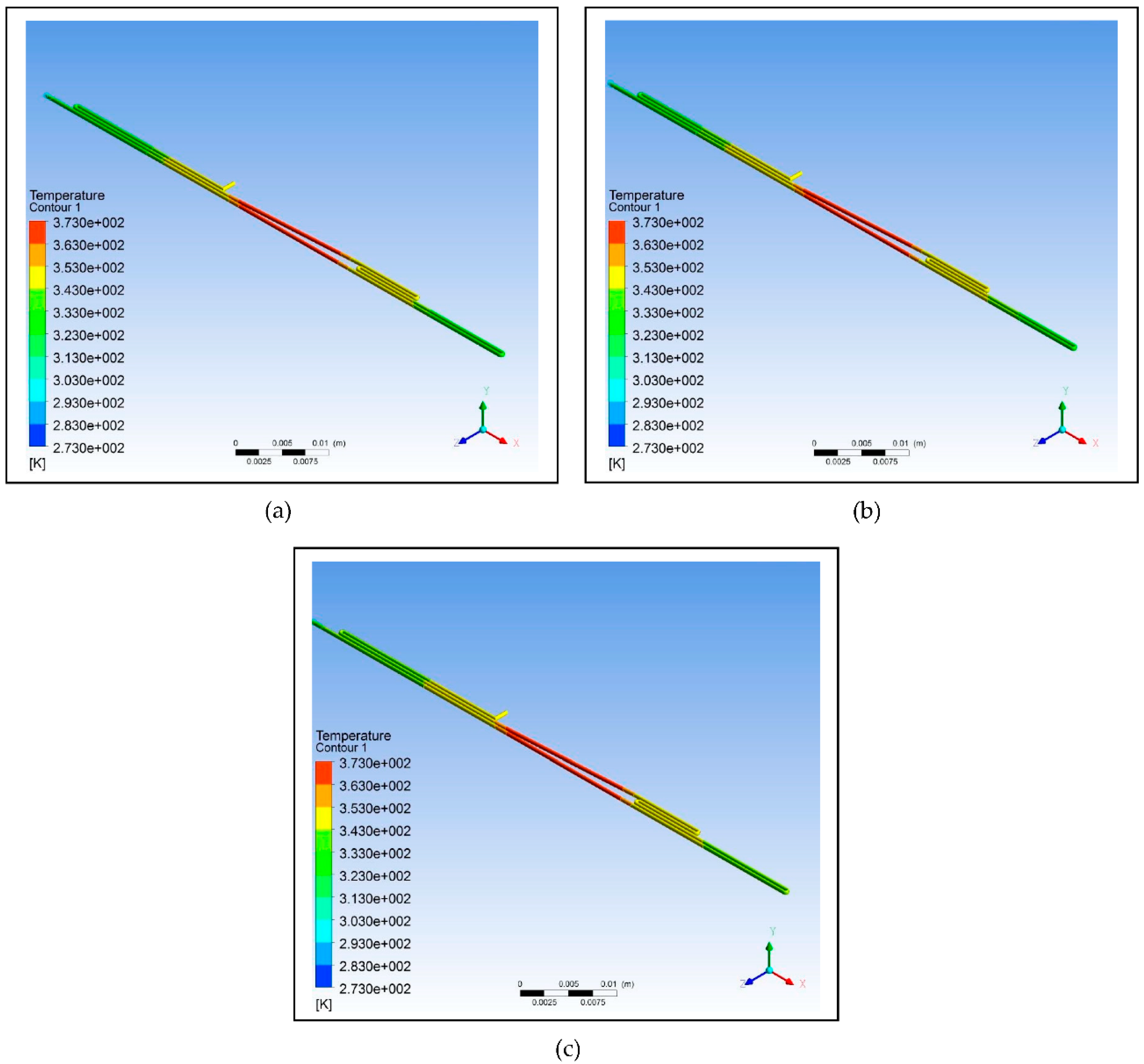
Figure 6.
Polycarbonate microfluidic PCR chip design set at temperatures of: (a) 58°C (annealing), 72°C (extension), and 95°C (denaturation); (b) 60°C (annealing), 74°C (extension), and 97°C (denaturation); (c) 63°C (annealing), 77°C (extension), and 100°C (denaturation).
Figure 6.
Polycarbonate microfluidic PCR chip design set at temperatures of: (a) 58°C (annealing), 72°C (extension), and 95°C (denaturation); (b) 60°C (annealing), 74°C (extension), and 97°C (denaturation); (c) 63°C (annealing), 77°C (extension), and 100°C (denaturation).
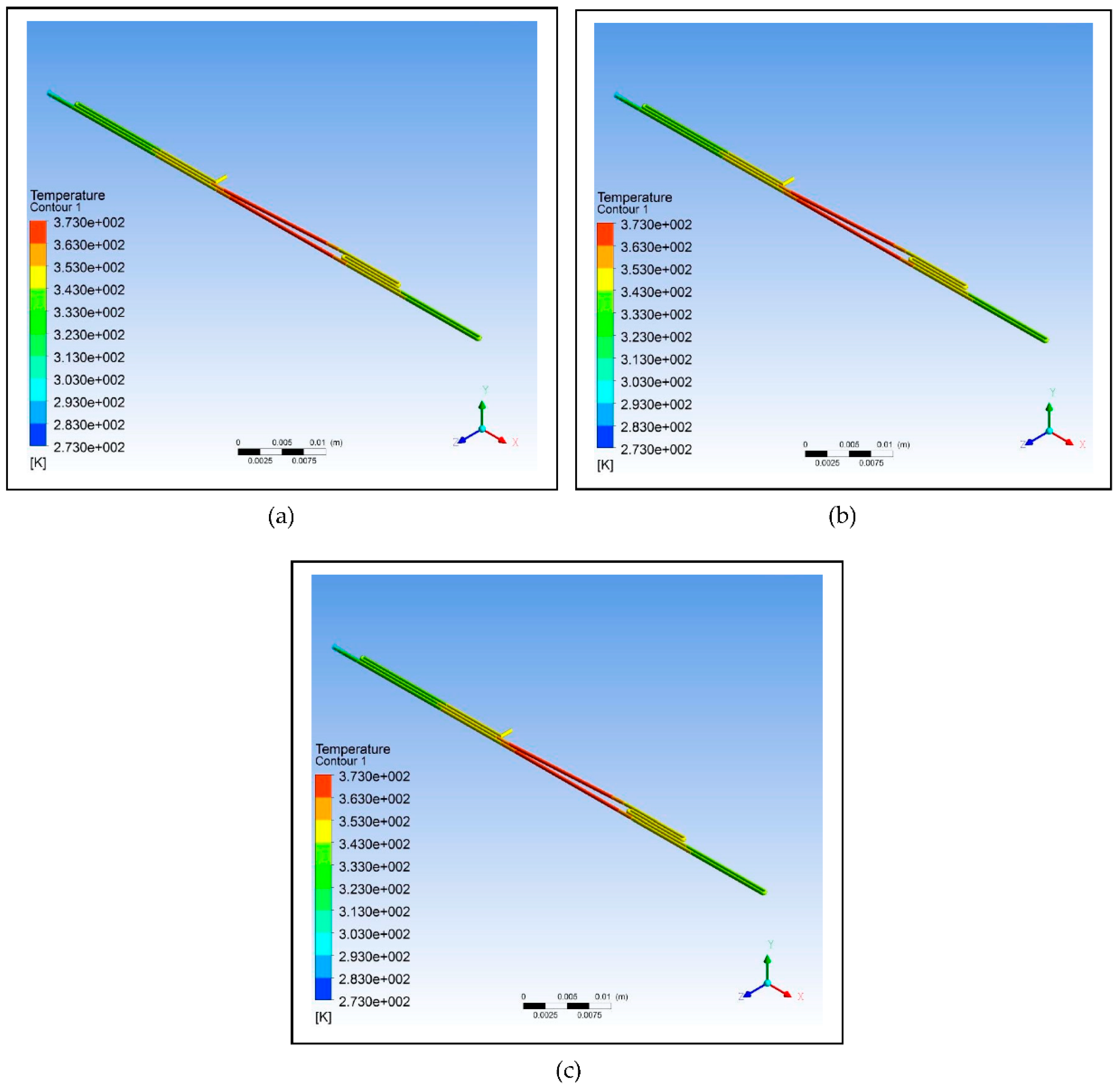
Figure 7.
Polydimethylsiloxane microfluidic PCR chip design set at temperatures of: (a) 58°C (annealing), 72°C (extension), and 95°C (denaturation); (b) 60°C (annealing), 74°C (extension), and 97°C (denaturation); (c) 63°C (annealing), 77°C (extension), and 100°C (denaturation).
Figure 7.
Polydimethylsiloxane microfluidic PCR chip design set at temperatures of: (a) 58°C (annealing), 72°C (extension), and 95°C (denaturation); (b) 60°C (annealing), 74°C (extension), and 97°C (denaturation); (c) 63°C (annealing), 77°C (extension), and 100°C (denaturation).
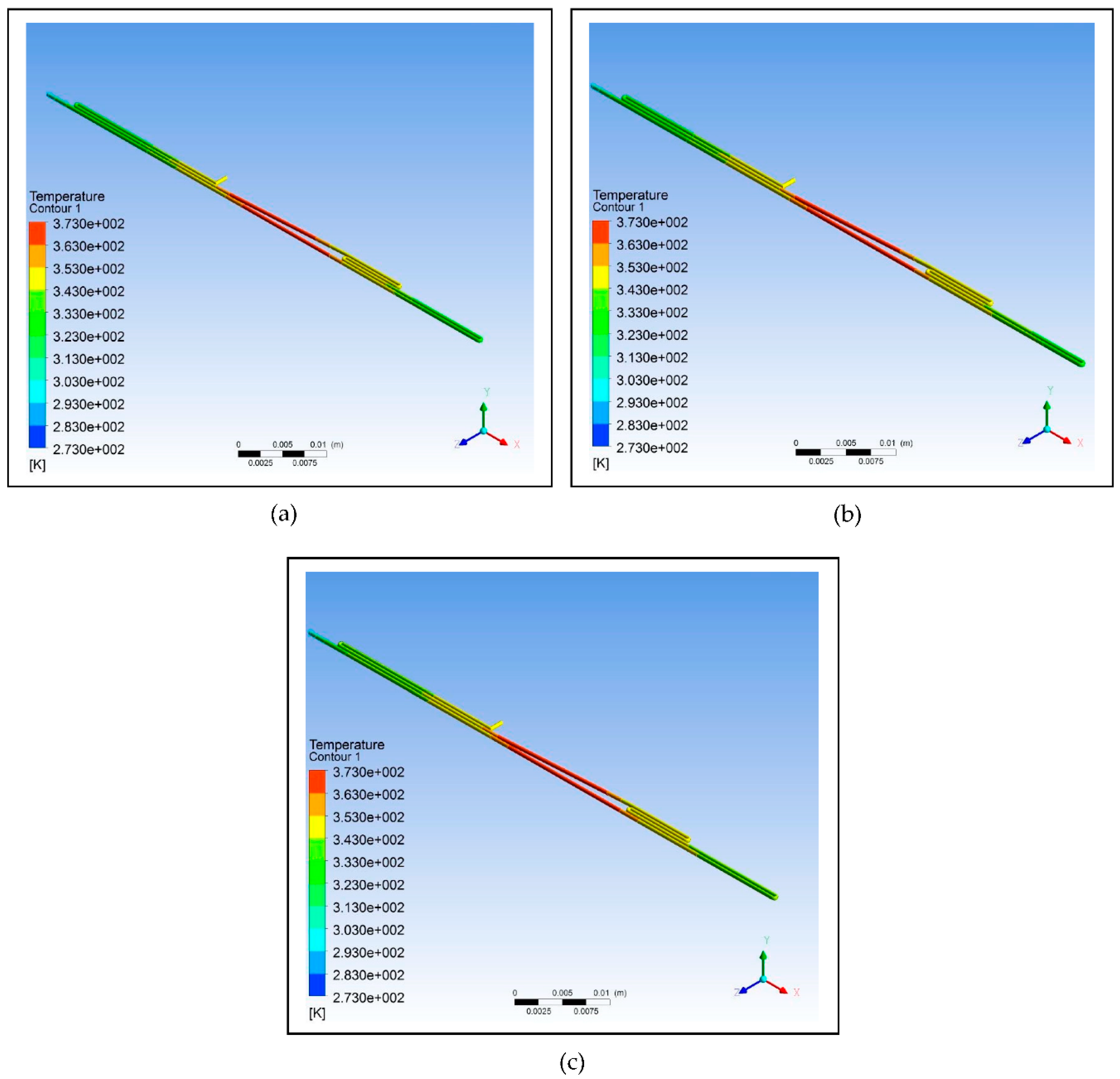
Figure 8.
Polypropylene microfluidic PCR chip design set at temperatures of 58°C (annealing), 72°C (extension), and 95°C (denaturation) with dimensions of: (a) 300 μm (diamater), 200 μm (length), and 130686 μm2 (cross-sectional area); (b) 500 μm (diamater), 300 μm (length), and 346350 μm2 (cross-sectional area).
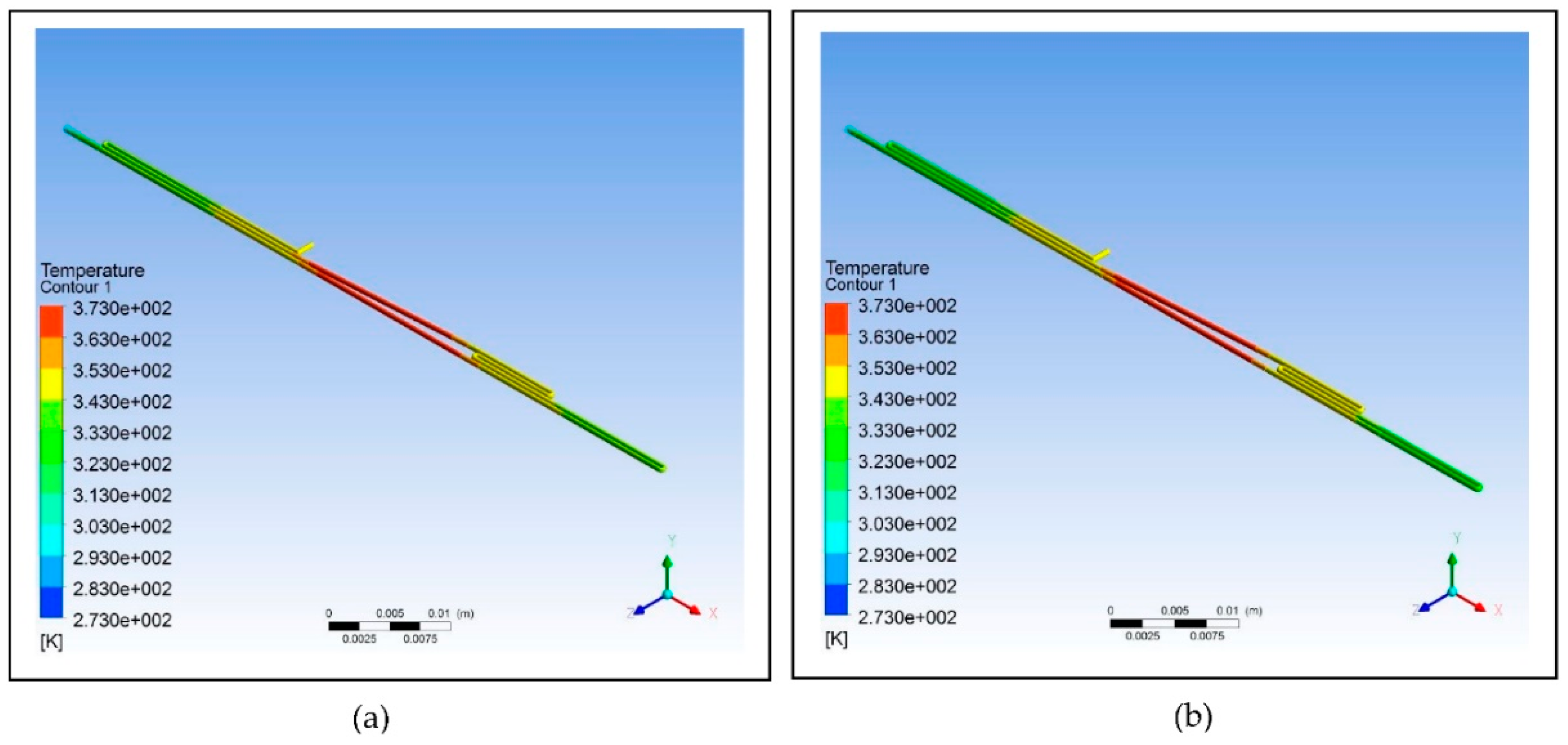
Table 2.
The types of polymeric material with their corresponding thermal properties used in designing the microfluidic PCR chip.
Table 2.
The types of polymeric material with their corresponding thermal properties used in designing the microfluidic PCR chip.
| Material Property | Unit | [17] | [18] | [19] |
|---|---|---|---|---|
| Melting Point | 432.15 | 428.15 | 408.15 | |
| Thermal Conductivity | 0.8 | 0.24 | 0.15 | |
| Specific Heat | 1.8 | 1.2 | 1.46 | |
| Density | 920 | 1200 | 970 |
; ;
Table 3.
The dimensions of the three designs utilized in the simulation.
| Total Length Calculation | ||||
|---|---|---|---|---|
| Design | Radius (mm) | Circumference (mm) | Length (mm) | Total Length (mm) |
| - | - | 30 | 30 | |
| 0.25 | 1.570796327 | 14 | 30 | |
| 0.25 | 1.570796327 | 27 | 30 | |
Table 4.
The dimensions of the microfluidic PCR chip and the copper plate.
| Parts | Length (mm) | Width (mm) |
|---|---|---|
| Microfluidic Chip | 73 | 45.5 |
| Denaturation | 15 | 45.5 |
| Annealing | 15 | 45.5 |
| Extension | 10 | 45.5 |
| Space | 2 | - |
Table 5.
Other parameters considered in the design of the microfluidic PCR chip.
| Region | Residence Time (s) | Length (µm) | Passes | Volume | Volumetric Flowrate | Speed (µm/s) |
|---|---|---|---|---|---|---|
| Annealing (58°C) | 15 | 15000 | 1.5 | 2.94E+09 | 1.96E+08 | 1500 |
| Extension (72°C) | 20 | 10000 | 3 | 3.92E+09 | 1.96E+08 | 1500 |
| Denaturation (95°C) | 10 | 15000 | 1 | 1.96E+09 | 1.96E+08 | 1500 |
| Spaces | 5.3 | 8000 | 1.05E+09 | 1.96E+08 | 1500 | |
| Total | 153 | 75500 | 3 | 9.87E+09 |
Table 6.
The dimensions used in determining the effect of changing the cross-sectional area of the design on the fluid temperature. Two designs with different diameters and lengths were tested.
Table 6.
The dimensions used in determining the effect of changing the cross-sectional area of the design on the fluid temperature. Two designs with different diameters and lengths were tested.
| Parameter | Unit | Design 1 | Design 2 |
|---|---|---|---|
| Diameter | μm | 300 | 500 |
| Length | μm | 200 | 300 |
| Cross-Sectional Area | μm2 | 130686 | 346350 |
Table 7.
The effect of looping on the efficiency of the design based on the calculation of relative deviation and ASD.
Table 7.
The effect of looping on the efficiency of the design based on the calculation of relative deviation and ASD.
| Design | Relative Deviation | |
|---|---|---|
| No Loop | 0.65 | 1.12 |
| One Loop | 0.80 | 1.39 |
| Two Loops | 0.88 | 1.52 |
Table 8.
The effect of the different polymeric materials under various temperatures on the efficiency of the design based on the calculation of relative deviation and ASD.
Table 8.
The effect of the different polymeric materials under various temperatures on the efficiency of the design based on the calculation of relative deviation and ASD.
| 58°C, 72°C, 95°C | 60°C, 74°C, 97°C | 63°C, 77°C, 100°C | ||||
|---|---|---|---|---|---|---|
| Material | Relative Deviation | Relative Deviation | Relative Deviation | |||
| 0.94 | 3.21 | 2.84 | 5.82 | 6.90 | 25.00 | |
| 1.92 | 8.61 | 3.15 | 10.00 | 6.92 | 26.70 | |
| 2.78 | 14.00 | 3.47 | 14.00 | 6.93 | 29.00 | |
;
Table 9.
The effect of changing the parameters of the polypropylene microfluidic PCR chip under the temperatures of 58°C (annealing), 72°C (extension), and 95°C (denaturation) on the efficiency of the design based on the calculation of relative deviation and ASD.
Table 9.
The effect of changing the parameters of the polypropylene microfluidic PCR chip under the temperatures of 58°C (annealing), 72°C (extension), and 95°C (denaturation) on the efficiency of the design based on the calculation of relative deviation and ASD.
| Parameter | Design 1 | Design 2 |
|---|---|---|
| Diameter | 300 | 500 |
| Length | 200 | 300 |
| Relative Deviation | 0.94 | 2.31 |
| 3.21 | 5.96 |
Table 10.
The time consumed for the different number of cycles.
| No. of Cycles | Time (minutes) |
|---|---|
| 20 | 51.01 |
| 25 | 63.77 |
| 30 | 76.52 |
| 35 | 89.27 |
| 40 | 102.03 |
| 44 | 112.23 |
Disclaimer/Publisher’s Note: The statements, opinions and data contained in all publications are solely those of the individual author(s) and contributor(s) and not of MDPI and/or the editor(s). MDPI and/or the editor(s) disclaim responsibility for any injury to people or property resulting from any ideas, methods, instructions or products referred to in the content. |
© 2023 by the authors. Licensee MDPI, Basel, Switzerland. This article is an open access article distributed under the terms and conditions of the Creative Commons Attribution (CC BY) license (http://creativecommons.org/licenses/by/4.0/).
Copyright: This open access article is published under a Creative Commons CC BY 4.0 license, which permit the free download, distribution, and reuse, provided that the author and preprint are cited in any reuse.


