Submitted:
05 May 2023
Posted:
05 May 2023
You are already at the latest version
Abstract
Extensive research has been conducted on printable antenna technologies, believed to be fast-growing due to their significant impact on wireless devices. It is necessary to study the progress of printable antenna technology as they are core devices for wireless technology today. This review work offers a comprehensive account of the previous and recent research achievements based on the principle of printable antenna, and parametric studies of several key design parameters, for future wireless network applications. The systems considered for evaluation include broadband techniques, large Bandwidth, high gain, dual/multi-band, or reconfigurable structure, low-profile, size-reduction, compact, linear, or circular polarization applications. It also highlights the fabrication procedures, and the numerous material characteristics affecting the antenna performance for various wireless applications with design considerations. Fully printed antennas on different substrates and conductive ink were investigated, including polyethylene terephthalate (PET), synthetic paper (Teslin), resin-coated photo paper, and Kapton polyimide substrates, among many others. The findings show that the fully inkjet-printed antenna made fabrication easy, improving the accuracy and conductivity of the printed patterns by concentrating on the inherently difficult problems and opportunities. Inkjet-printed antennas are believed to be the futuristic demand for sustainability and wireless solution in several ways.
Keywords:
printable antenna
; inkjet-printed
; gain
; Bandwidth
; and broadband
1. Introduction
The printable antenna technology in wireless transmission rapidly attracts growing interest in mobile communication technology. It has broad growth prospects, a rich spectrum of resources, promising potential, and many different applications that can extend well to the high-frequency band. Thus, for practical applications, size reduction and bandwidth widening have emerged as key design challenges of printable antennas. A simple design of a copper Microstrip antenna achieved a stable in-band omnidirectional radiation pattern in the form of a wheel-shaped in the operation of the 24 GHz frequency band [1,2]. The impacts of conductor thickness on a mathematical model on the centre frequency for the low profile, more economical antenna for 5G application was achieved [3]. An air-substrate antenna was designed and fabricated to reduce the fabrication cost and operate at the 28 GHz frequency band [4,5]. Improved Bandwidth and gain were achieved on a microstrip patch and meander line antenna [6]. A boundary condition for substrate thickness and conductive material for a low-profile, cost-effective centre frequency, Bandwidth, gain, and efficiency of antenna operation was achieved [7]. Good radiation efficiency, wide Bandwidth, gain, and reduced mutual coupling between radiators were achieved by an air substrate [8]. In [9], a significant increase in Bandwidth was successfully achieved using a perforated stacked cylindrical dielectric resonator. The limitations of the printable antenna’s large size and poor radiation efficiency were improved using a quasi-lumped element resonator antenna technology [10]. A high gain, cost-effective, low profile, and economical antenna operation were achieved using an effective thickness of conductive material and an air-substrate-based antenna [11].
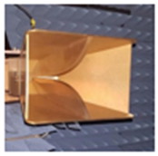
Figure 1.
(a) schematic for a single-element antenna, (b) a model diode, and (c) results of S11 [12].
Figure 1.
(a) schematic for a single-element antenna, (b) a model diode, and (c) results of S11 [12].
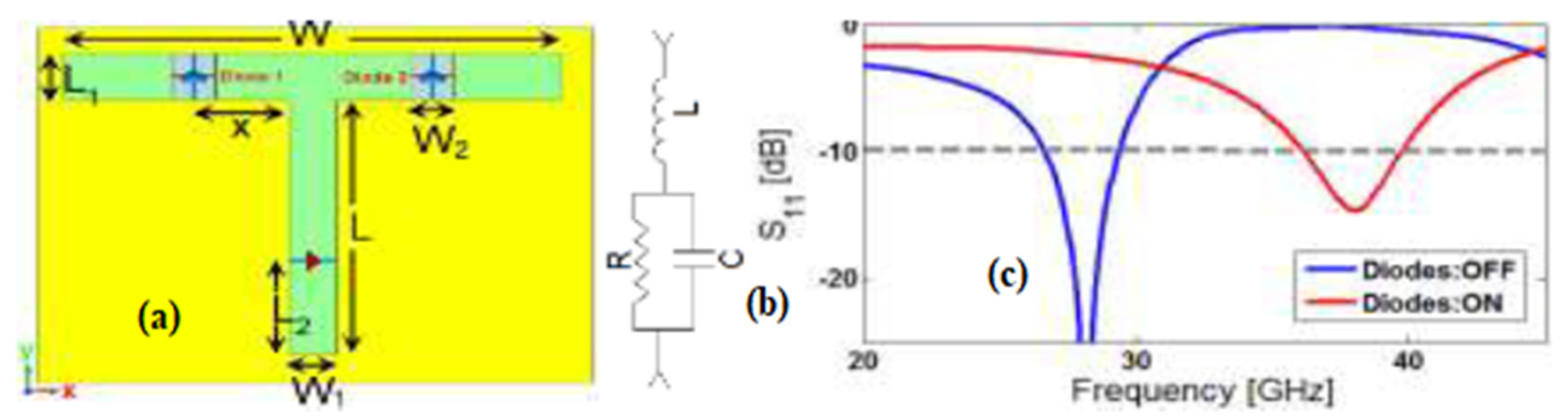
The antenna operating in mm-wave transmission demands high gain and wider Bandwidth because of faster transmission and the Bandwidth spectrum, which are the most critical wireless communication issues [13]. Antenna design in mm-wave wireless technology for mobile phones has been a challenging research topic for higher frequency band applications [14,15]. Microstrip and hollow waveguides have been used to build mm-Wave multi-beam antennas as traditional transmission lines technology in [14] and, antenna in packages operating in high frequencies reduces the high-demand interconnect loss with 5G deployment [16]. To handle significant loss in free space, high traffic rate, Bandwidth scarcity, gain, and quality of millimeter wave frequency and directive antenna system for future high-frequency band wireless applications. The future technology would employ wide signal bandwidth and high-frequency bands to boost transmission bit rates and improve coverage, which is the future’s main objective of wireless networks with millimeter waves [17]. A microstrip antenna has the beam steering capability needed to facilitate wireless communication between mobile terminals due to its light, compactness, and integration into the module circuit. Supporting the mobile terminal of wireless communication networks is necessary. Recent development led to the design of an antenna that will transmit and receive high gain that can be operated in a high-frequency range, to achieve a higher data rate and improved antenna reliability by inkjet-printed technology [17].
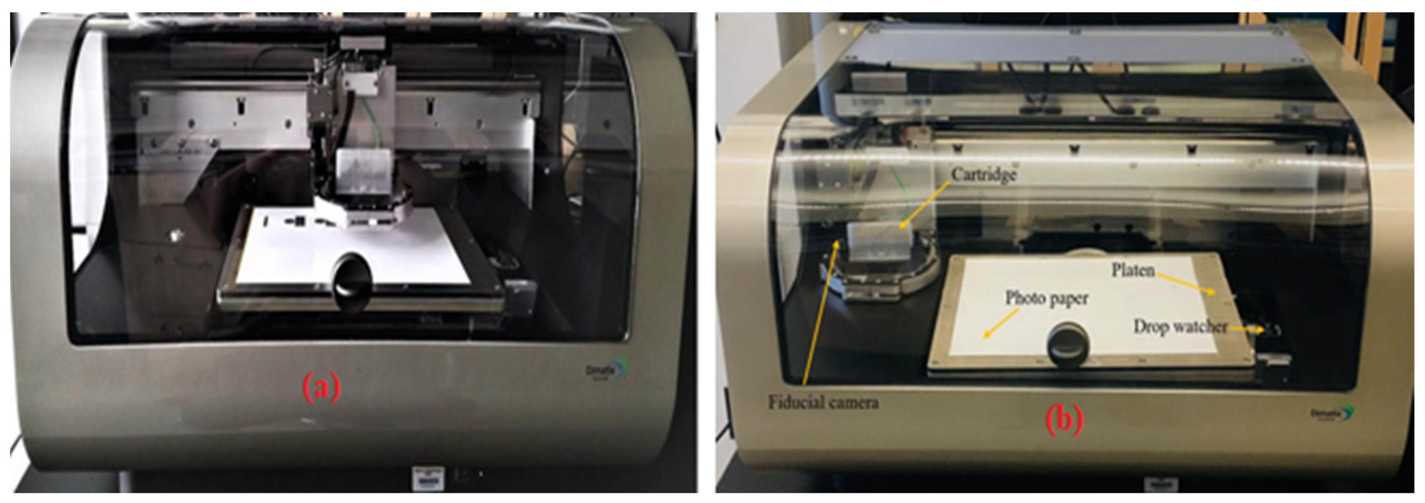
Figure 2.
Antenna printed with an inkjet using silver nanoparticles and paper substrate. (a) When using the Fujifilm’s Dimatix 2831 inkjet printer (b) Description of the Fujifilm’s Dimatix Inkjet Printer, DMP 2831 [18].
Figure 2.
Antenna printed with an inkjet using silver nanoparticles and paper substrate. (a) When using the Fujifilm’s Dimatix 2831 inkjet printer (b) Description of the Fujifilm’s Dimatix Inkjet Printer, DMP 2831 [18].
Broadband antennas are necessary because several wireless applications, both established and new, operate across a wide range of frequency bands. Many design issues must be resolved for reasonable tradeoff inconsistencies in technology design, low-profile, or low-cost manufacturing techniques. This work aims to review the optimization of printable antenna design and fabrication. And it examines the latest developments in the different methods to give readers an idea of its possible advantages over conventional low-gain antennas. The information provided in this review is assumed to be used as a reference, especially for new researchers taking up a career in printable antenna technology, presenting an easy-to-read summary of recent accomplishments and comparison points for new antenna technology. The spectrum of printable antenna prototypes, low-profile, compact designs, broadband with increased gain, reconfigurable designs, a survey of linear and planar arrays, and integrated systems are all covered in this article on printable antenna technologies. Printable antennas on polymer-based materials represent one of the solutions for the low degree of freedom [19]. Short-range communications and wireless coverage of complex network environments were improved [17]. To achieve data rates of up to 10 Gbps and latency of below 1 ms using a printable antenna operating in a millimeter-wave frequency band is necessary [20].
Figure 3.
(a) Printed antenna placed in a flat position on a wood surface (b) Tensile bending over a mandrel with a 1-inch radius [21].
Figure 3.
(a) Printed antenna placed in a flat position on a wood surface (b) Tensile bending over a mandrel with a 1-inch radius [21].
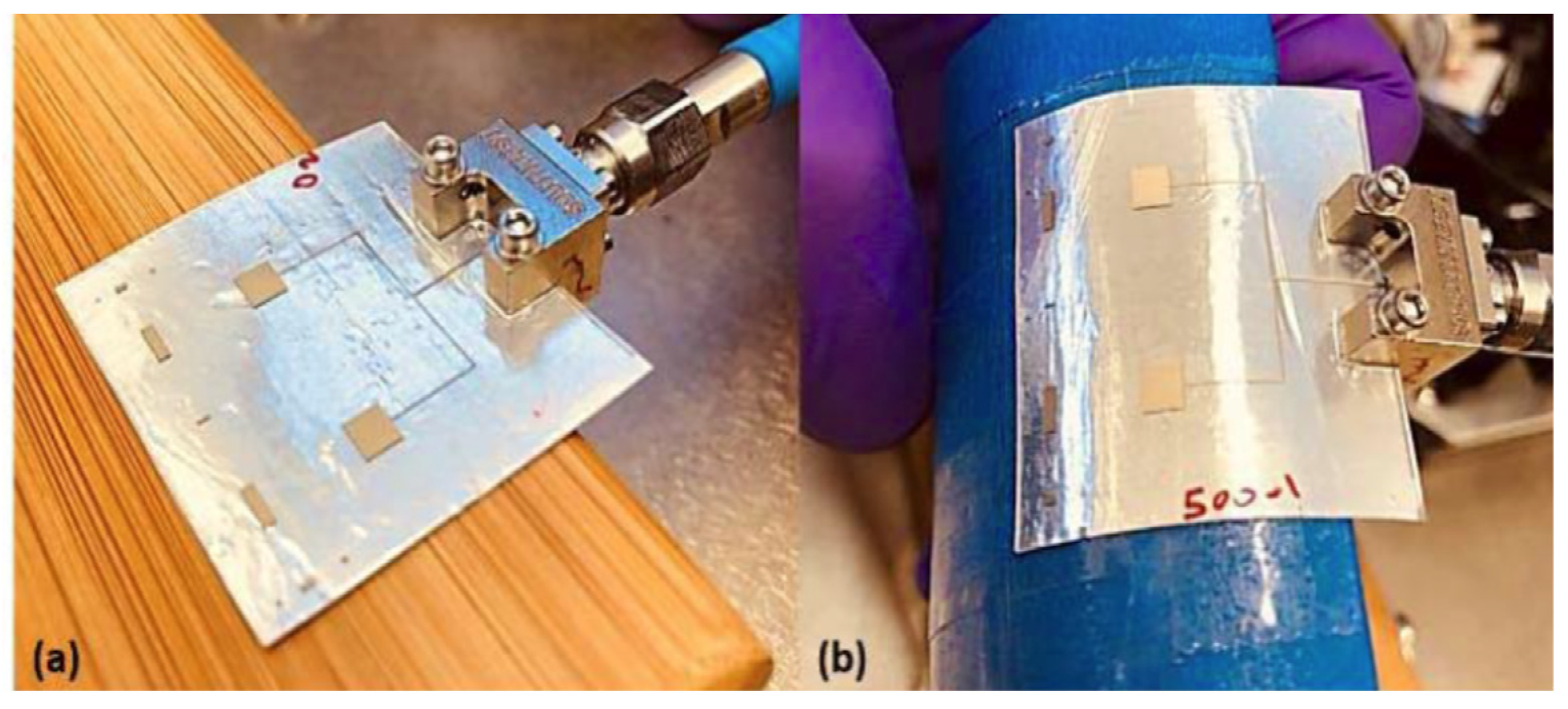

Table 1.
Various types of antennas with their functions [22].
Table 1.
Various types of antennas with their functions [22].
| Types | Name and Functions | Types | Name and Functions |
|---|---|---|---|
| Narrow Band | |||
 |
Microstrip Patch => A resonant patch to a 50-ohm transmission line | 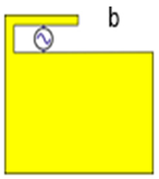 |
Inverted F Antenna => Phones use single-sided resonant structures as their GPS antenna |
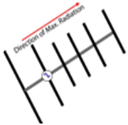 |
Yagi-Uda => Narrowband directional antenna, used for point-to-point communications | 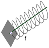 |
Helical Antenna => Narrowband directional or omnidirectional antenna based on dimensions of helix |
| Wide Band | |||
 |
Planar Bow Tie => Wideband planar antenna, here seen as a single-sided configuration | 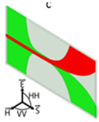 |
Antipodal Vivaldi => Wideband planar antenna, the same geometry used in this thesis |
 |
Horn Antenna => Wideband antenna, 1 GHz to 18 GHz calibration | 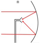 |
Parabolic Reflectors => are used as “Satellite Dishes” with horn antenna for satellite TV |
2. Antenna Design and Fabrication
Most of the 3D Printing approaches fall into two primary categories polymer/dielectric or all-metal, the preferred 3D printers produce objects with high spatial resolution, thin build layers, and smooth surfaces, with the printed pieces’ quality significantly affecting the antenna’s performance [23]. A dual-band stacked microstrip patch array antenna and a 3D electromagnetic-based have been designed and fabricated for wide bandwidth efficiency and low-cost implementation [24]. A relatively straightforward U-slot microstrip patch antenna was designed and fabricated with wide Bandwidth and a very good beam width [25]. A high-order mode cavity-backed cross-dipole antenna and High-efficiency layer-driven air-filled waveguide feeder and a unique hybrid coupler were designed. and cheap fabrication cost to increase the gain by lowering the feed loss [26]. Due to the high-speed signal transmission, the antenna needs to have changed from single-band to dual-band, from SISO to MIMO implementations for antenna diversity, and now from single-band to multi-band [27]. Due to its small size and economical form, a Wide tuning band frequency configurable antenna could be easily integrated with modern communication equipment like smartphones, laptops, and other portable electronic devices [28].
In wireless communication, a microstrip patch antenna is commonly used to emit electromagnetic waves into space, made up of four basic parts: ground, substrate, patch, and feed, and has a ground plane on one side and a dielectric constant on the other and can be square, elliptical, circular, rectangular, or even a ring in shape. It is used in many industries, such as automotive, logistics, GPS, and microwave communication [29]. To realize multiband operation and better impedance matching, a modern dual annular ring microstrip antenna with gaps generates optimal high gain and impedance performance Bandwidth [30]. A microstrip slot antenna is chosen because it is low profile and easy to design and fabricate, giving researchers a greater understanding of how antennas function and their features [31].
Figure 4.
The proposed dual-band staircase patch antenna filled with CSRR unit cells in the design stages (a) an antenna with a rectangular patch and a complete ground plane (b) A staircase patch antenna with a defective ground plane that has been optimized (c) CSRR unit cells are fitted into the final planned optimized Staircase antenna [32].
Microstrip Patch Antenna could be determined as the length and width (in millimetres) of a rectangular patch antenna using equations 1 to 9, as well as the radius of the patch antenna can be determined by equations as shown below. The following equations can calculate the design parameters, and a crucial design parameter, the resonance frequency is determined by the patch length.
The antenna’s patch length L is specified as:
The patch’s length is greater electrically than its physical, the length L is provided as follows when considering the normalized extension of the length:
The effective dielectric constant, which is less than the actual dielectric constant, gives rise to ΔL it uses this effective dielectric constant to explain the fringing phenomenon.
The width calculation equation is presented as:
The effective dielectric constant’s value is given as shown below:
The substrate’s acceptability determines the dimensions. The electrical resistance the patch’s characteristics are also dependent on the antenna’s size and permittivity. The ground plane’s length (Lg) and width (Wg) are calculated using equations 3 & 7.
A resonant cavity antenna concept is used in the design and fabrication of an innovative all-metal antenna; the figures below show the various antenna configuration comprising a 140 GHz simulated antenna radiation pattern [33].
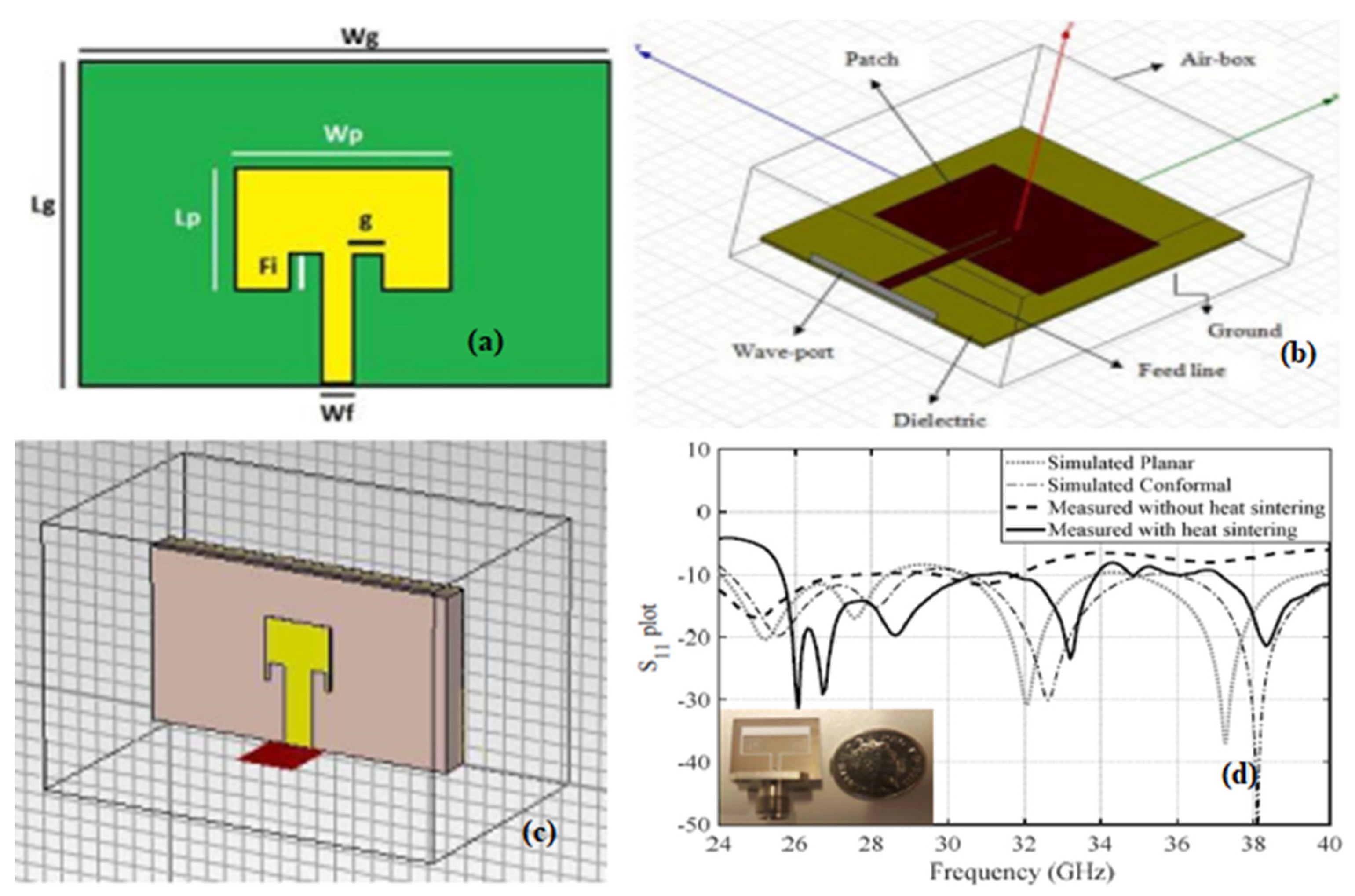
Figure 5.
(a) Microstrip patch antenna, (b) radial system for IEEE 33 buses (c) Microstrip patch antenna simulation in CST (d) The flexible inkjet-printed antenna’s S11 plot on PET film [29,34].
A horizontal array of polarized antennas: According to antenna array principles, element-to-element spacing close to is desired to radiate in the broadside direction, and all the array’s elements are created to be excited in phase at the center frequency of the operating band (28 GHz) [35]. The horizontally polarized antenna array’s design principles are also applied to the vertically polarized array [36]. An antenna array often referred to as a phased array, is a set of 2 or more antennas. A small 28-GHz phased array antenna focuses on the observed radiation patterns, which, even without calibration, exhibit good features (Beam steering range, beamwidth, side lobe level, cross-polar discrimination, etc) [37]. A small, phased array antenna with a low profile obtains hemispherical coverage in one direction only in the boresight direction [38].
A dual-polarized patch operating at 28 GHz, the antenna array built using a printable antenna method supports both horizontal and vertical polarizations and is appropriate for integrating phased array modules [39]. The feeds for leaky-wave antennas are designed in printable form, and the lenses are manufactured of plastic to produce a low-profile and inexpensive solution. To increase the array element aperture efficiency, the feeds’ near-field region features lenses that are optimized for it [40]. New antenna design and integration techniques enable a low-cost, scalable antenna in-package phased-array system for wideband wireless communication [41]. To maximize array performance, an air-filled substrate-integrated waveguide cavity-backed patch antenna array with eight dual-polarized elements transmits high-speed data reliably between access points and end-user terminals [42]. A 2x64 dual-beam array with low cost is fabricated using flip-chip technology, and a dual-polarized 5G transmitter phased antenna array achieves at 50 and 25 GHz and has an EIRP of 52 dBm at Psat, respectively [43].
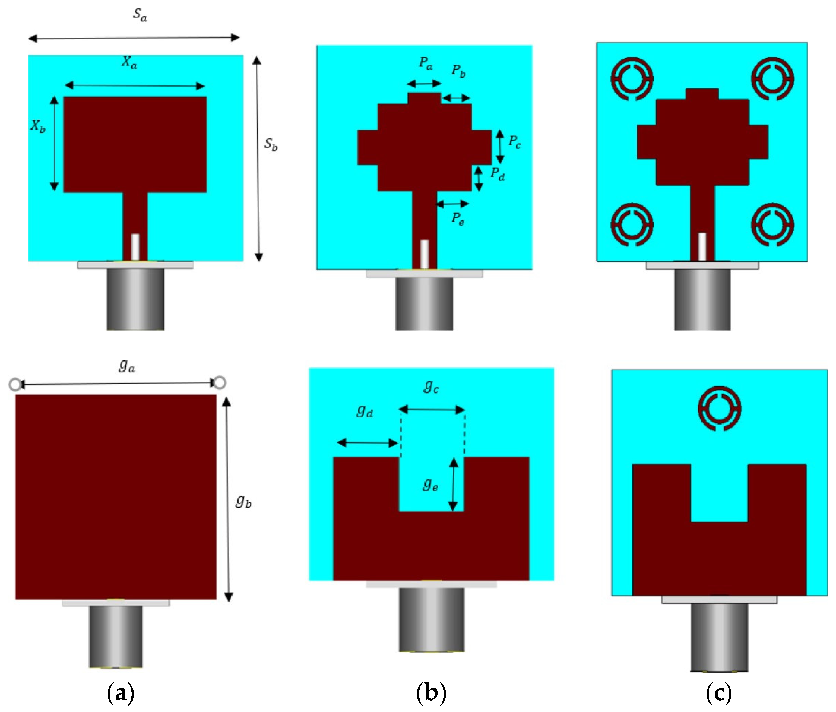
Figure 6.
Antenna on PET film with inkjet printing: (a) model simulation; (b) conformal antenna simulation; (c) antenna prototype that was conformally fabricated [34].
Figure 6.
Antenna on PET film with inkjet printing: (a) model simulation; (b) conformal antenna simulation; (c) antenna prototype that was conformally fabricated [34].
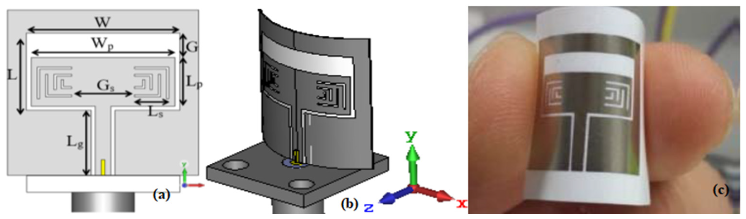
Table 2.
Various types of antennas with their functions [22].
Table 2.
Various types of antennas with their functions [22].
| Fc (GHz) | Materials (Substrates) | Technology | εr | Eff. % | Size(mm3) | BW (GHz) | Gain (dBi) | RL (dB) | Ref. |
|---|---|---|---|---|---|---|---|---|---|
| 125/280 | glass & Kapton | inkjet print. | NA | NA | 63.5×63.5×0.05 | 35/70 | 24/145 | 10 | [44] |
| 94 | LCP | inkjet print. | 2.6 | NA | 210×297×0.15 | 8.1 | 7.65 | 10 | [45] |
| 28 | Ultra-thin glass | inkjet print. | 5.4 | 80 | 7.13×5.4×0.147 | 5.4 | 6.96 | 10 | [46] |
| 26.5/37 | PET | inkjet print. | 3.2 | 95 | 16×19×0.135 | 1.2/3 | 7.2/9.7 | 10 | [47] |
| 60 | PET | inkjet print. | NA | NA | 50×60×0.11 | 2.7 | 24.4 | 10 | [48] |
| 28 | ABS Fingernail | inkjet print. | 2.7 | 70 | 14.96×117.45×0.5 | 2.87 | 7.5 | 10 | [49] |
| 28 | FLGR02 | inkjet print. | 3 | NA | 5×9×1.7 | 8 | 5 | 10 | [50] |
| 34 | PET | inkjet print. | 3.2 | NA | 11×25.4×0.147 | 12.7 | 6.2 | 10 | [51] |
| 26.26 | PET | inkjet print. | 3.2 | NA | 3.1×3.4×0.15 | NA | NA | 10 | [21] |
| 39 | PET | inkjet print. | 3.2 | NA | 12×4.7×0.123 | 26–40 | 7.44 | NA | [34] |
| 28 | PET | Spray coating | 3.38 | 70 | 7.11×3.556×0.508 | 2.5 | 8.8 | 10 | [52] |
| 35 | LCP | inkjet print. | 2.9 | NA | 11×12×0.1 | 14 | 9 | NA | [53] |
| 28 | Polyester fabric | Screen print. | 2.2 | NA | 25×12.7×0.35 | 7.8 | 4.2 | 18 | [54] |
| 28 | RO4350 | PCB | 2.2 | 45.6 | 3.53×3.53×0.16 | 6.72 | 19.2 | 10 | [55] |
| 28 | Roger RO3003 | PCB | 3 | - | 130×70×0.762 | 24 | 8 | 10 | [13] |
| 28 | FR-4 | PCB | 2.2 | N/A | 2.50×3.20×0.1 | 1 | 11.23 | 10 | [56] |
| 28 | TLY-5A | PCB | 2.17 | N/A | 3.3×3.3×0.254 | 0.9 | 10 | 13.8 | [57] |
| 28 & 38 | RT 5880 | PCB | 2.2 | N/A | NA | 2 & 4 | 10 | 13 | [12] |
| 28 | FR4 | PCB | 4.4 | 85 | NA | 7.2 | 10.8 | 10 | [58] |
| 28 & 38 | RT/D6002 | PCB | 2.2 | 63/81 | 30×30×1.52 | 4.3/5.3 | 8.7/8.2 | 10 | [32] |
| 28 | RO4003C | PCB | 2.2 | N/A | 2×2.2×0.25 | 4 | 5.5 | 12 | [16] |
| 50 | FR 04 | PCB | 4.4 | N/A | 40×34×4.8 | 20 | 7.5 | 10 | [59] |
| 60 | N/A | PCB | - | 85 | 15×15×3 | 3.6 | 18.5 | 10 | [60] |
| 60 | Isola tachyon | BGA | 3.02 | 90 | 9.6×2.8×0.568 | 3.6 | 10.51 | <10 | [61] |
| 60 | RT 5880 | PCB | 2.2 | NA | NA | 4 | 17.1 | 40 | [62] |
| 60 | PTFE | PCB | 2.2 | 57.2 | 44.5×20.0×2.16 | 5.6 | 15.6 | 2.1 | [63] |
| 140 | RGD837 | LTCC | NA | 77.5 | 7×7×2.5 | 19.17 | 15.5 | 13 | [33] |
* BW = Bandwidth; N/A = Not Available, Fc = Centre Frequency, εr = Dielectric Constant, LTCC = Low-temperature co-fired ceramic, PET = Polyethylene Terephthalate, LCP = Liquid Crystal Polymer, PTFE = poly tetra fluoro ethylene, BGA = Ball Grid Array, TLY-5A = Butler matrix, Duroid = D.
3.1. Fabrication Methods for Printable Antennas
Different types of various parameters determine the performance of the antenna, such as the conductivity of the radiation element, different design considerations, dielectric substrates, Bandwidth, efficiency, and gain. Selecting a suitable dielectric material to enhance the critical performance of the antenna and gain and efficiency are believed to be decreased for a greater value of dielectric substrate loss [123]. Different substrates determine the performance of a printable antenna using the fabrication process. The common fabrication methods include screen printing and inkjet printing, wet-etching, and other special techniques for fabricating flexible and wearable antennas [13,64]. A branch line coupler with pliers-shaped ends and its transition layer was used to fabricate a low profile and compact novel 2x2 slot array antenna, making the feeding network layers suitable for future wireless applications [65]. Graphene ink was created by the radiating element and the active channel of field effect transistors are inkjet printed using graphene flakes. The printable substrate used to print circuitry for antenna and electronics on a flexible surface and the radiation-emitting materials’ flexibility and rate of oxidation obtained [66].
Figure 7.
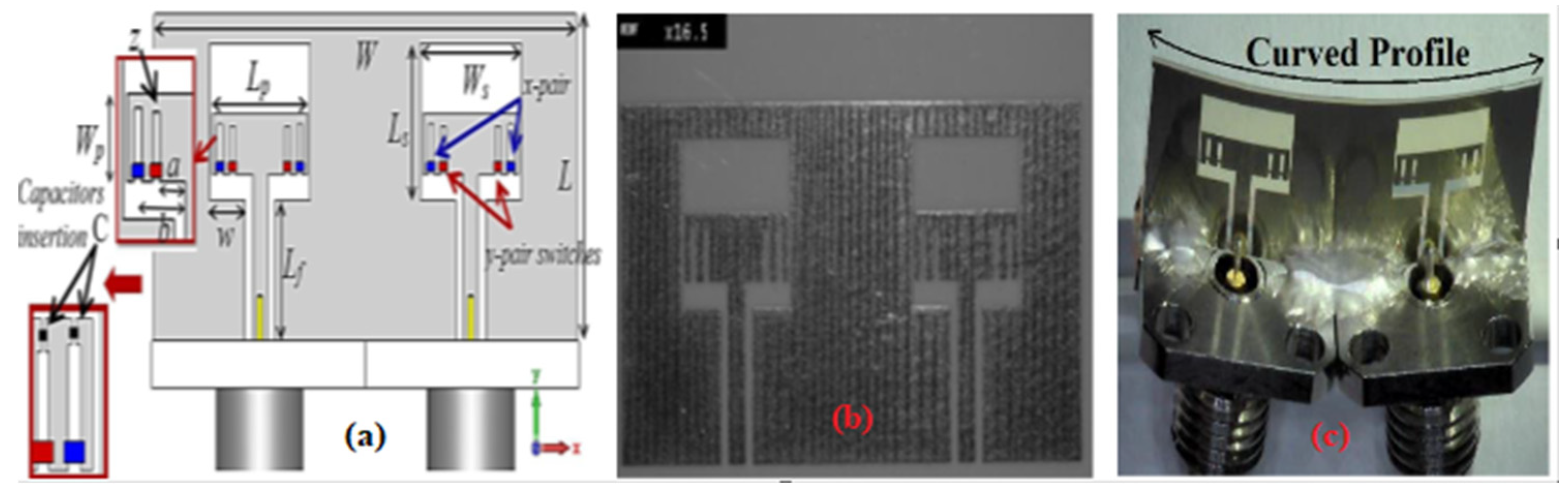
Proposed printable MIMO antenna with two elements: (a) model of a simulated antenna; (b) fabricated antenna prototype that was inkjet printed; (c) actualized conformal 2-element MIMO antenna [51].
Figure 7.
Proposed printable MIMO antenna with two elements: (a) model of a simulated antenna; (b) fabricated antenna prototype that was inkjet printed; (c) actualized conformal 2-element MIMO antenna [51].
3.2. Conductive materials
Achieving conductive patterns in wireless applications with superior electrical conductivity is necessary to guarantee a wide bandwidth and higher gain. Moreover, resistance deterioration brought on by mechanical deformation is the desired feature of the conductive material. Fabrics must be tightly knitted and made of adequately conductive material, and deviations from the main current flow in the opposite direction must be avoided [67]. Copper/silver are frequently chosen for the fabrication of printable antennas because they possess a high electrical conductivity due to the low rate of oxide formation copper nanoparticles are edged by silver nanoparticle ink [23,68].
Table 3.
Radiation characteristics measured using various conductive layer materials [67].
Table 3.
Radiation characteristics measured using various conductive layer materials [67].
| Gain (dBi) | X-polarization ratio (dB) | Beam width (deg) | |||
|---|---|---|---|---|---|
| Solid copper tape | 7.35 | -20.42 (E) | -18.55 (H) | 73 (E) | 60 (H) |
| Knitted copper fabric | 6.77 | -16.03 | -17.74 | 75 | 54 |
| Vertically cut copper tape | 6.82 | -17.73 | -18.52 | 74 | 61 |
| Horizontally cut copper tape | 5.01 | -20.83 | -17.99 | 74 | 62 |
| Horiz. cut and soldered copper tape | 7.26 | -24.72 | -18.90 | 73 | 62 |
| Aracon fabric | 0.57 | -12.09 | -15.73 | 75 | 60 |
3.3. Substrates
The material used as the substrate in printable antennas needs low relative permittivity, low thermal expansion coefficient, good thermal conductivity, and minimal dielectric loss conductivity in different environments, such is motivated by the requirement for greater efficiency at the expense of higher antenna size. It is mentioned earlier, an exception to this fact is the need for a miniaturized antenna for a huge dielectric constant. Three different categories of substrates have regularly surfaced in the fabrication of printable antennas, thin glass, plastics or polymer, and metal foil substrates [69]. a high-density inductively linked plasma at low temperature (90–170 °C) vapor deposition method is required, allowing any substrate to be used for a printable antenna; it has the desired electrical characteristics for antenna applications [70].
Figure 8.
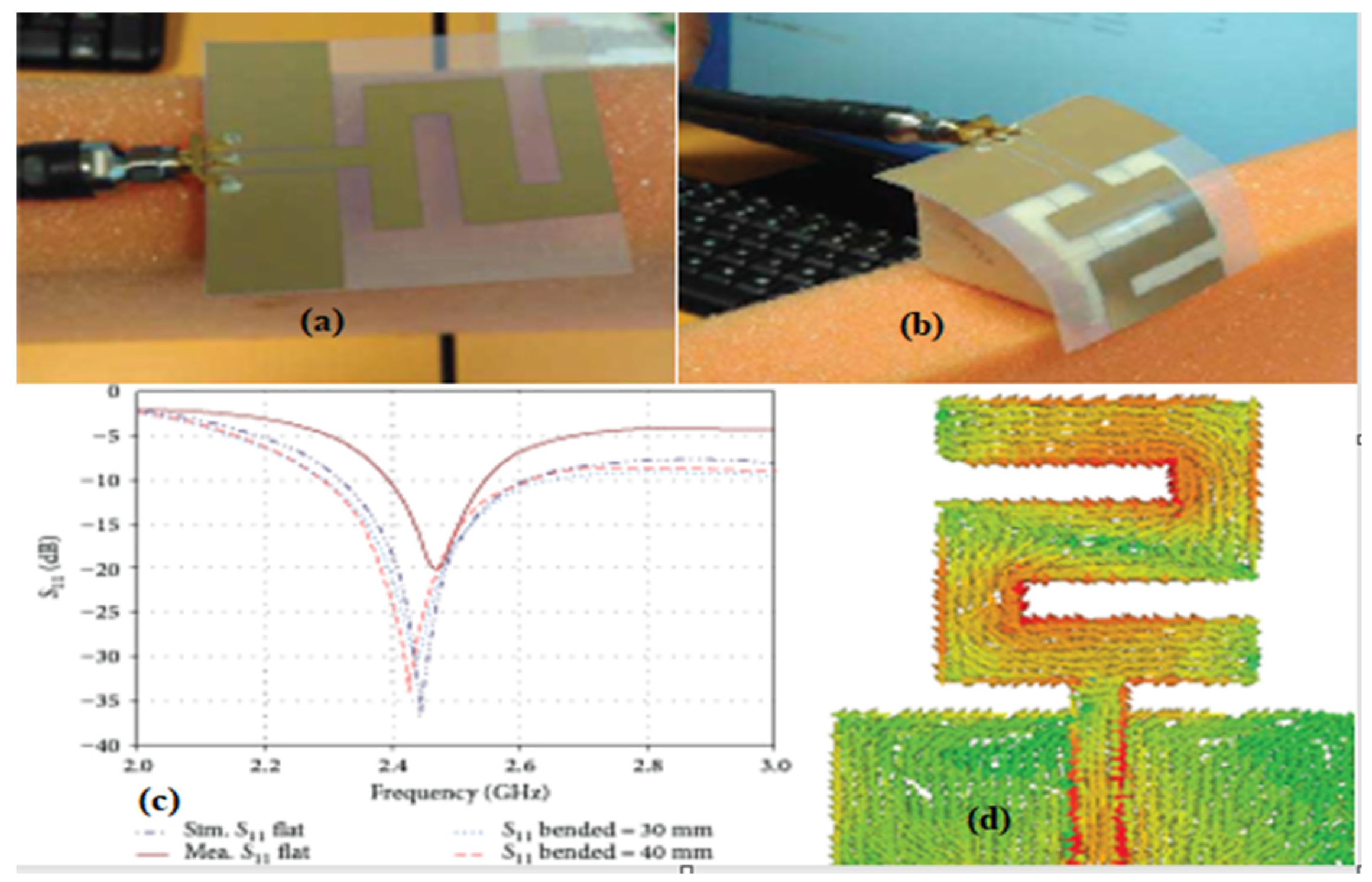
Z-shape antenna fabricated using the inkjet printing method on PET substrate (a) flat condition (b) state of bending (radius: 20mm) (c) reflecting factor S11 in decibels (d) The antenna’s simulated current distribution at 2.45GHz [71].
Figure 8.
Z-shape antenna fabricated using the inkjet printing method on PET substrate (a) flat condition (b) state of bending (radius: 20mm) (c) reflecting factor S11 in decibels (d) The antenna’s simulated current distribution at 2.45GHz [71].
3.4. Chemical Etching
Chemical etching was part of the printable antenna industry in the process of fabricating metallic patterns using etchants and photoresists corrosively mill out a chosen area [72]. It is the ideal option over other fabrication techniques for accurately fabricating complicated designs with high resolution [73].
Figure 9.
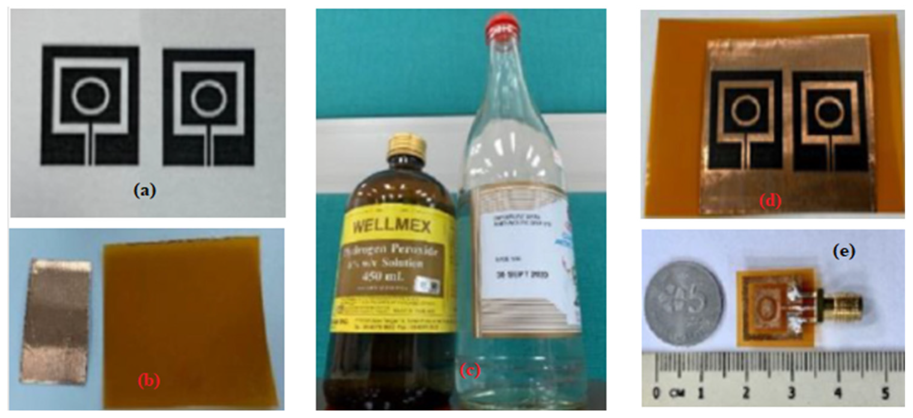
Fabrication Prototype (a) printed design (b) polyimide Kapton film with copper tape (c) chemical substances (d) designed transferred (e) complete prototype.
Figure 9.
Fabrication Prototype (a) printed design (b) polyimide Kapton film with copper tape (c) chemical substances (d) designed transferred (e) complete prototype.
4.1. 3D-Printed Antenna
Creating completed parts that might be utilized for final user applications without any process is a desirable aspect of metal three-dimensional (3D) printing for time and cost. Stainless steel 316L and aluminium AlSi10Mg are common choices for materials [74]. Two planar transitions from the rod antenna microstrip to excite the orthogonal modes are proposed, along with a dielectric rod antenna with dual polarization for polarization diversity applications at a 35 GHz frequency band. The antenna is printable using a commercial 3D printer, which results in a very low fabrication cost [75]. The developed filtering antenna has very small profiles and demonstrates great selectivity, gain, and efficiency. It blends a selective filter and Yagi-Uda-like antenna within a 3D printable metal construction [76]. A monopole microstrip antenna design was fabricated using a 3D-printed curved substrate fed with a microstrip line and a partially formed ground plane [77].
Figure 10.
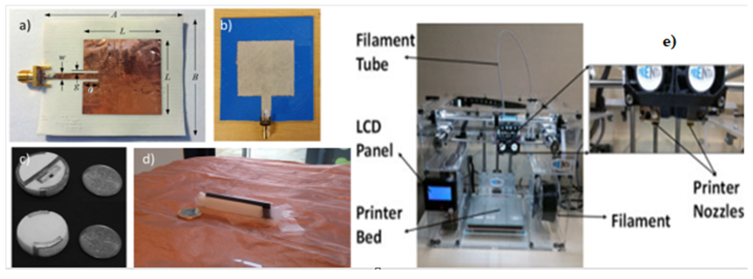
Examples of Antennas made via 3-D printing: (a) Ninja Flex substrate with a square patch antenna, (b) a 3-D printed substrate with a brush-painted wearable antenna, (c) 3-D radio-frequency identification (RFID) tag antenna in the form of a button, (d) Inverted antenna made via 3D printing [23] and, (e) a 3-D printer [78].
Figure 10.
Examples of Antennas made via 3-D printing: (a) Ninja Flex substrate with a square patch antenna, (b) a 3-D printed substrate with a brush-painted wearable antenna, (c) 3-D radio-frequency identification (RFID) tag antenna in the form of a button, (d) Inverted antenna made via 3D printing [23] and, (e) a 3-D printer [78].
4.2. Screen Printing
Screen printing is an easy, inexpensive, fast, and effective method for fabricating an antenna by printing using conductive inks or pastes onto low-cost substrates such as PET, textiles, and paper [79]. Planar dielectric antennas are introduced using thick film screen-printing technology to serve as a magnetic wall boundary, and a micron-sized thick film formed of a low-loss substrate is printed using high-permittivity dielectric paste., low-permittivity microwave substrate [80]. Transparent silver nanowire is used in screens printed on a flexible PET substrate, for innovative applications demanding transparent and flexible antennas [81].

4.3. PCB Printing
Different conductive materials and substrates are used to fabricate PCB antennas and the substrate should be selected based on its dielectric properties and electrical conductivity. These must be tolerance to persistence in the external environment and mechanical deformations; the radiation efficiency determines the antenna performance based on the selection of conductive material. The small antenna structure was developed using HFSS software to show the 3D view to achieve a wideband resonating response, the PCB structure the copper patch’s top geometry is etched, and FR-4 substrate coaxial feed is applied in depicts the structure’s dimensions [83,84]. A full-wave analysis of a resonant cavity antenna served as the basis for the design of an all-dielectric phase-correcting structure that is 3D printable [85]. The phase correction was accomplished by simultaneously varying the permittivity and height of the dielectrics [86].
Figure 12.
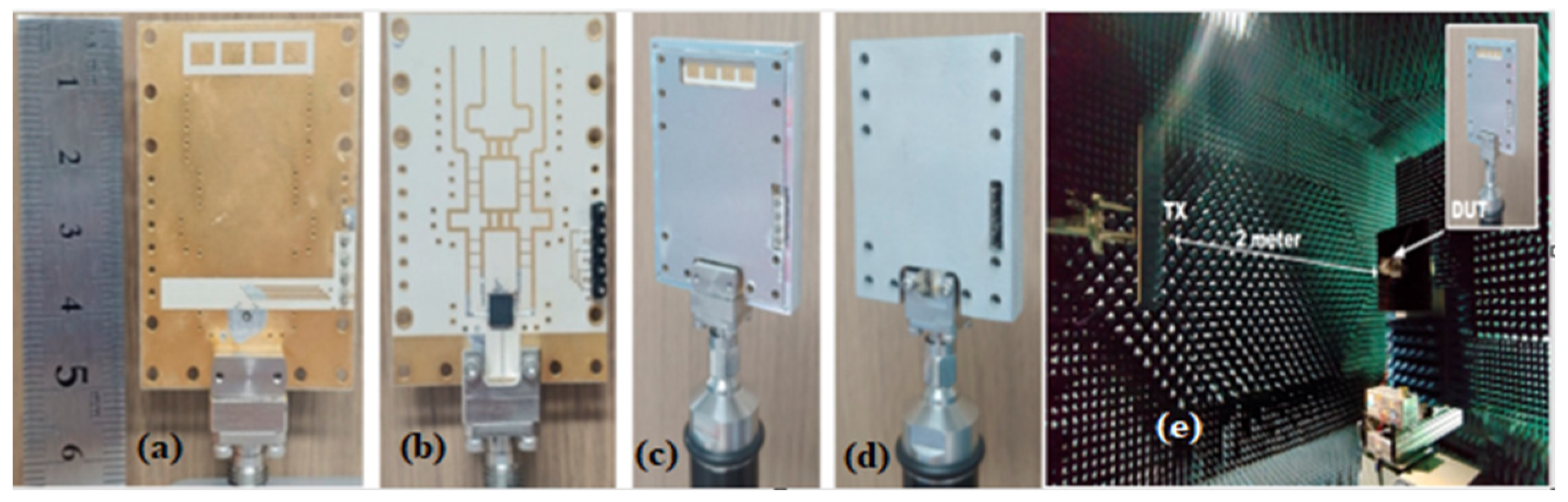
The fabricated antennas in pictures (a) Antenna side (b) Butler matrix side (c) A metal enclosure’s antenna side, (d) a metal enclosure’s reverse side, (e) Test configuration for the radiation pattern in the anechoic chamber [87].
Figure 12.
The fabricated antennas in pictures (a) Antenna side (b) Butler matrix side (c) A metal enclosure’s antenna side, (d) a metal enclosure’s reverse side, (e) Test configuration for the radiation pattern in the anechoic chamber [87].
4.4. Inkjet Printing
Technology for inkjet printing has developed alternatively to traditional fabrication methods such as milling and etching. The method is additive; thus, the design is directly applied to substrate 3 without masks and guarantees minimal wasting of materials [88]. A circularly polarized antenna construction is proposed to be formed on adhesive copper for a practical prototype. The dielectric support will be 3D-printed in Poly Lactic Acid, wisely chosen for its intriguing low losses qualities [89]. The inkjet printing technology’s promise of reactive inkjet printing for commercializing wearable electronics based on graphene has guaranteed the antenna’s mechanical flexibility and extremely low production costs [90]. The production of patch antennas, circuit boards, biological sensors, frequency selection surfaces, and various electronic gadgets has extensively used inkjet printing [91]. substrate-integrated waveguides and antenna-in-package are printed entirely with inkjet technology to improve the performance of three parts: via holes, wire bonding, and flexible antenna arrays [92]. Fabrication of planar antennas for inkjet printing technical issues concerns the dimensions of the manufactured structures, as well as the efficient nanoparticle ink is applied to a PET substrate using a piezoelectric printhead [93].
Figure 13.
Experimental platform for laser sintering [91], An inkjet-printed Antenna using silver nanoparticles on a paper substrate.
Figure 13.
Experimental platform for laser sintering [91], An inkjet-printed Antenna using silver nanoparticles on a paper substrate.
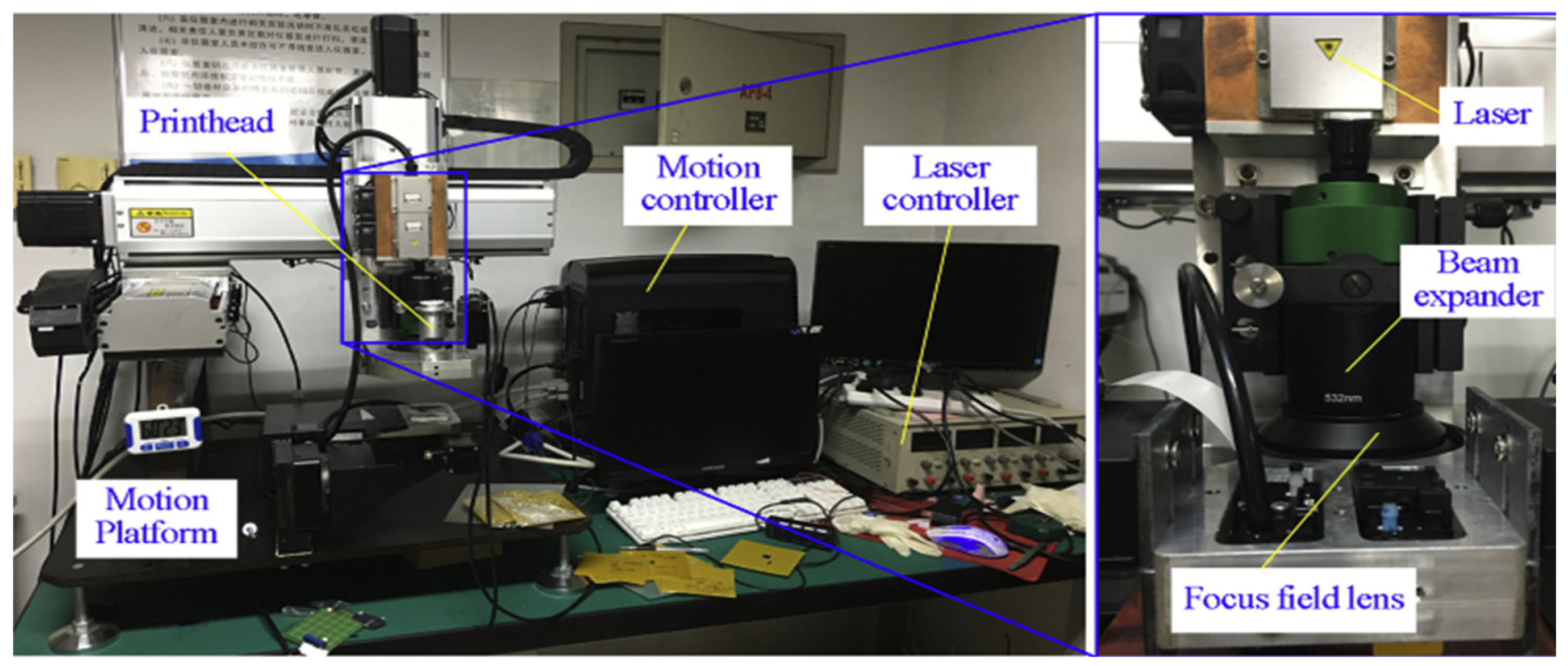
Table 4.
Comparatives Analysis of Different Inkjet-Printed Antenna Designs for Operating at Different Frequencies.
Table 4.
Comparatives Analysis of Different Inkjet-Printed Antenna Designs for Operating at Different Frequencies.
| Antenna Type | FcGHz | Tech. | substrate | Ink type | Subεr | Sub.tan δ | Size (mm2) | SH mm2 | BW(GHz) | Gain(dBi) | Ref. |
|---|---|---|---|---|---|---|---|---|---|---|---|
| Multi-Band | 5 | Inkjet Print. | Teslin | Nanoparticles | 2.00 | 0.022 | 35×40 | 0.26 | 1 | 2 | [82] |
| Monopole | 12.4 | Inkjet Print. | polyimide | silver nanoparticle | 3.5 | 0.0027 | 13×13 | 0.125 | 5.4 | 4.4 | [94] |
| NA | 2.4 | Inkjet Print. | PET | GO ink | 3.2 | 0.022 | 75*5 | 0.84 | NA | [95] | |
| Multiband | 3.4 | Inkjet Print. | Photo paper | silver nanoparticle | 3.2 | 0.05 | 30x40 | 0.44 | 2.5 | 2 | [96] |
| mimo monopole | 3.4 | Inkjet Print. | Kapton polyimide | silver nanoparticle | 3:4 | NA | 22*31 | 0.125 | 3.43 to10.1 | 2.31 | [97] |
| Patch Antenna | 4.9 | Inkjet Print. | Kapton polyimide | silver nanoparticle | 3.4 | NA | 22×31 | 0.245 | 0.25 | 4.5 | [98] |
| monopole | 2.45.2 | Inkjet Print. | photo paper | silver nanoparticle | 3 | NA | 51*34 | 0.18 | 0.451.60 | 1.42.78 | [99] |
| Dual-Ban | 2.45/5.8 | Inkjet Print. | PET | silver nanoparticle | 3.2 | 0.022 | 45×40 | 0.135 | 0.83/2.55 | 1.81/3.92 | [100] |
| Dual-Band | 2.4/ 5.2 | Inkjet Print. | photopaper | nanoparticle silver | 3 | NA | 210×282.5 | 0.177 | 0.5/2.9 | 3.74/4.96 | [101] |
| graphene | 5.65 | Inkjet Print. | Polyamide | graphene | 3.5 | 0.002 | 9×7 | 0.125 | 3 | 0.35 | [102] |
| Patch antenna | 2.45 | Inkjet Print. | Ninja Flex | Silver paste | 2.8 | 0.05 | 65×54 | 0.2 | 0.99 | 7.2 | [78] |
| Dipole | 2.45 | Inkjet Print. | porous elastomer | Graphene | 3.6 | 0.06 | NA | NA | 0.9 | 0.3 | [103] |
| Patch | 1.11 | Inkjet Print. | PET | Silver ink | 4 | 0.01 | 30×40 | 0.135 | 0.037 | NA | [104] |
| Monopole | 2.55 | Inkjet Print. | Textile substrate | Silver ink | 3.74 | 0.15 | 37.5×23 | 0.49 | 2.09 | 1.5 | [105] |
| monopole | 2.4/5.8 | Inkjet Print. | photo paper | silver nanoparticle | 3.2 | 0.05 | 86.25/22 | 0.22 | 0.71/1.96 | 2.24/4.42 | [106] |
| Dipole | 3.8 | Inkjet print. | Wound dressing | Nano silver Ink | 3.2 | 0.05 | 43.5×42.5 | 0.7 | 3.2–4.6 | 0.67 | [107] |
| monopole | 2.45 | Inkjet print. | PET | Silver nanoparticle | 2.7 | 0.135 | 30×40 | 0.125 | NA | 1.44 | [71] |
* tan δ = loss factor; SH = thickness of the substrate, εr = dielectric.
5. Future Prospects and Challenges of Inkjet-printed Antennas
The research on inkjet-printed antennas for use in wireless devices attracted considerable attention because of their ability to conform to the standards of wireless applications. An inkjet-printed antenna is one of the essential parts to replace conventional rigid substrates in the fabrication process for wireless systems [108]. Consequently, the first challenge of designing an inkjet-printed antenna is finding an appropriate substrate; compared to traditional substrates like Rogers or FR4, which need a dielectric constant of about 3 to 10 and a loss tangent of 0.001 to 0.02, typical inkjet-printed substrates have low dielectric constants [109]. Though, this dielectric constant value helps attain better radiation efficiency, and Bandwidth, when miniaturization is needed, it causes difficulty with antenna functionality. For inkjet-printed textile antennas, the uneven thickness is another problem. The electro-textile substrate is predisposed to crumble easily and be absorbent of liquid.
6. inkjet-printed Antenna for Future Wireless Solutions
As a result of the increased demand for wireless applications, inkjet-printed antennas are expected to be used in a wide range of frequencies for future wireless solutions. There are various antenna techniques, including reconfigurable, single-band, and multiband antennas. Frequently, multiband design is required; for instance, in 5G wireless technology, devices should operate in the mm-wave 28GHz and above range. Additionally, the design would assure that the characteristics of the antenna remain constant under design specification conditions. In a previous article, an inkjet-printed multiband antenna was designed and fabricated at a low-cost [110]. Based on a Kapton polyimide-based material, the innovative triangular iterative design features a coplanar waveguide feed inkjet-printed substrate was applied to achieve multiband operation with wider Bandwidth [111].
7. Conclusions
The findings from this study present the significance of printable antennas in various frequency bands, with challenges and restrictions along with various miniaturization strategies. The problems with the conducting ink and substrate were analyzed for wireless system solutions in the future, including with reference to contemporary literature. The selection of materials for printable antenna fabrication depends on application preferences such as the environment, smooth integration with rigid and non-rigid devices, cost, and components of the fabrication process.
The inkjet-printed antenna technology is ideal for current and future wireless communication devices due to their simplicity of fabrication, lightweight, small-form component, inexpensive production, and capacity to fit non-planar surfaces among many more. The conductive patterns in the inkjet-printed antennas have been more viable alternatives to the conventional ones, due to highly conductive materials including Ag nanoparticle paints, Cupper tape, or clad conductive polymers. And graphene-based materials such as printing ink. PET, PEN, PANI, liquid crystal polymer, electro-textile, paper, and Kapton polyimide substrates to ease the fabrication process. The major challenge of antenna design for inkjet printing is substrate material selection, which requires a low-loss material to improve antenna efficiency.
References
- Kamal, S.; et al. Wheel-shaped miniature assembly of circularly polarized wideband microstrip antenna for 5G mmWave terminals. Alexandria Engineering Journal 2021, 60. [Google Scholar]
- Mohammed, A.S.B.; et al. Mathematical Modelling on the Effects of Conductive Material and Substrate Thickness for Air Substrate Microstrip Patch Antenna. Appl Comput Electromagn Soc J 2020, 35. [Google Scholar]
- Mohammed, A.S.B.; et al. Mathematical model on the effects of conductor thickness on the centre frequency at 28 GHz for the performance of microstrip patch antenna using air substrate for 5G application. Alexandria Engineering Journal 2021, 60. [Google Scholar]
- Kamal, S.; et al. A Novel Lumped LC Resonator Antenna with Air-Substrate for 5G Mobile Terminals. Progress In Electromagnetics Research Letters 2020, 88, 75–81. [Google Scholar] [CrossRef]
- Kamal, S.; et al. A 28 GHz mmWave Circular Microstrip Antenna with Rectangular Slots on Air-Substrate. In Proceedings of the 2020 IEEE International RF and Microwave Conference (RFM); 2020; pp. 1–4. [Google Scholar] [CrossRef]
- Kamal, S.; et al. A novel negative meander line design of microstrip antenna for 28 GHz mmwave wireless communications. Radioengineering 2020, 29, 479–485. [Google Scholar] [CrossRef]
- Mohammed, A.S.B.; et al. Analysis of the Proposed Boundary Conditions for the Conductive Material and Substrate Thickness of Air-Substrate Microstrip Patch Antenna via Graphical Verification Method. In Lecture Notes in Electrical Engineering; 2022; Volume 829 LNEE. [Google Scholar] [CrossRef]
- Kamal, S.; et al. A Compact MIMO Antenna for Wideband Circularly Polarized mmWave Communications. In Lecture Notes in Electrical Engineering; 2022; Volume 829 LNEE. [Google Scholar] [CrossRef]
- Zubir, I.A.; et al. A low-profile hybrid multi-permittivity dielectric resonator antenna with perforated structure for Ku and K band applications. IEEE Access 2020, 8. [Google Scholar]
- Kamal, S.; et al. An Assessment of Progress in 5.8 GHz Quasi-lumped Element Resonator Antennas. IETE Technical Review (Institution of Electronics and Telecommunication Engineers, India). Taylor and Francis Ltd., 2021; Volume 38, no. 3, pp. 328–346. [Google Scholar] [CrossRef]
- Mohammed, A.S.B.; et al. Improving the Gain Performance of Air Substrate Patch Antenna Array Using the Effect of Conductive Material Thickness Study for 5G Applications. Journal of Physics: Conference Series 2020, 1529. [Google Scholar] [CrossRef]
- Ojaroudi Parchin, A.; Citation Ojaroudi Parchin N, R.A.; Yia, A.-Y. Frequency Reconfigurable Antenna Array for MM-Wave 5G Mobile Handsets Item Type Conference paper. 2018. Available online: http://hdl.handle.net/10454/16680.
- di Paola, C.; Zhang, S.; Zhao, K.; Ying, Z.; Bolin, T.; Pedersen, G.F. Wideband Beam-Switchable 28 GHz Quasi-Yagi Array for Mobile Devices. IEEE Trans Antennas Propag 2019, 67, 6870–6882. [Google Scholar] [CrossRef]
- Wang, J.; Wu, Y.; Wang, W.; Ma, L. Wideband mm-wave high-gain multibeam antenna array fed by 4 × 4 groove gap waveguide butler matrix with modified crossover. AEU—International Journal of Electronics and Communications 2022, 154, 154287. [Google Scholar] [CrossRef]
- Merlin Teresa, P.; Umamaheswari, G. Compact Slotted Microstrip Antenna for 5G Applications Operating at 28 GHz. IETE J Res 2020. [Google Scholar] [CrossRef]
- Salarrahimi, M.; et al. A Cost-Efficient 28 GHz Integrated Antenna Array with Full Impedance Matrix Characterization for 5G NR. IEEE Antennas Wirel Propag Lett 2020, 19, 666–670. [Google Scholar] [CrossRef]
- Ghosh, S.; Baghel, G.S.; v Swati, M. A low-profile, high gain, dual-port, planar array antenna for mm-wave powered 5G IoT systems. AEU—International Journal of Electronics and Communications 2022, 155, 154354. [Google Scholar] [CrossRef]
- Saha, T.K. High-performance antenna design for IoT, wearable, and 5G communications/. Washington State University: Pullman, Washington, 2019. [Google Scholar]
- Gu, C.; et al. A D-Band 3D-Printed Antenna. IEEE Trans Terahertz Sci Technol 2020, 10, 433–442. [Google Scholar] [CrossRef]
- Xu, B.; et al. Radiation Performance Analysis of 28 GHz Antennas Integrated in 5G Mobile Terminal Housing. IEEE Access 2018, 6, 48088–48101. [Google Scholar] [CrossRef]
- Khinda, G.S.; et al. Flexible inkjet-printed Patch antenna array on mesoporous PET substrate for 5G applications with stable RF performance after mechanical stress cycling. In Proceedings of the 2020 IEEE 70th Electronic Components and Technology Conference (ECTC); 2020; pp. 1824–1831. [Google Scholar] [CrossRef]
- Khan, A.Q.; Riaz, M.; Bilal, A. Various Types of Antenna with Respect to their Applications: A Review. International Journal of Multidisciplinary Sciences and Engineering 2016, 7. [Google Scholar]
- Kirtania, S.G.; et al. Flexible antennas: A review. Micromachines 2020, 11, 847. [Google Scholar] [PubMed]
- Belen, M.A. Design and realization of dual band stacked antenna via three-dimensional printing technology. Microw Opt Technol Lett 2020, 62. [Google Scholar] [CrossRef]
- Xu, J.; Ke, H.; He, Y.; Luo, Y. A Wideband U-Slot Microstrip Patch Antenna for Large-Angle Mmw Beam Scanning. In Proceedings of the 2018 IEEE International Conference on Computer and Communication Engineering Technology, CCET 2018; 2018. [Google Scholar] [CrossRef]
- Feng, B.; Tu, Y.; Chen, J.; Chung, K.L.; Sun, S. High-performance dual circularly-polarized antenna arrays using 3D printing for 5G millimetre-wave communications. AEU—International Journal of Electronics and Communications 2021, 130, 153569. [Google Scholar] [CrossRef]
- Jain, K.; Kushwah, V.S. Design and development of dual band antenna for sub-6 frequency band application. Mater Today Proc 2021, 47, 6795–6798. [Google Scholar] [CrossRef]
- Shah, I.A.; et al. Design and analysis of a hexa-band frequency reconfigurable antenna for wireless communication. AEU—International Journal of Electronics and Communications 2019, 98, 80–88. [Google Scholar] [CrossRef]
- Mishra, R.; Mishra, R.G.; Chaurasia, R.K.; Shrivastava, A.K. Design and analysis of microstrip patch antenna for wireless communication. International Journal of Innovative Technology and Exploring Engineering 2019, 8. [Google Scholar] [CrossRef]
- Godaymi Al-Tumah, W.A.; Shaaban, R.M.; Duffy, A.P. Design, simulation, and fabrication of a double annular ring microstrip antenna based on gaps with multiband feature. Engineering Science and Technology, an International Journal 2022, 29, 101033. [Google Scholar] [CrossRef]
- Ramprakash, K. Design, analysis and fabrication of a microstrip slot antenna. International Journal of Innovative Technology and Exploring Engineering 2018, 8. [Google Scholar]
- Singh, M.; Singh, S.; Islam, M.T. CSRR loaded high gained 28/38GHz printed MIMO patch antenna array for 5G millimeter wave wireless devices. Microelectron Eng 2022, 262, 111829. [Google Scholar] [CrossRef]
- Gu, C.; et al. A D-Band 3D-Printed Antenna. IEEE Trans Terahertz Sci Technol 2020, 10, 433–442. [Google Scholar] [CrossRef]
- Jilani, S.F.; Abbasi, Q.H.; Alomainy, A. Inkjet-Printed Millimetre-Wave PET-Based Flexible Antenna for 5G Wireless Applications. In Proceedings of the 2018 IEEE MTT-S International Microwave Workshop Series on 5G Hardware and System Technologies (IMWS-5G); 2018; pp. 1–3. [Google Scholar] [CrossRef]
- Tariq, S.; Psychoudakis, D.; Eliezer, O.; Khan, F. A new approach to antenna beamforming for millimeter-wave fifth generation (5G) systems. In Proceedings of the 2018 Texas Symposium on Wireless and Microwave Circuits and Systems, WMCS 2018; 2018. [Google Scholar] [CrossRef]
- IEEE Staff. 2017 Texas Symposium on Wireless and Microwave Circuits and Systems (WMCS). IEEE, 2017. [Google Scholar]
- Valkonen, R. Compact 28-GHz phased array antenna for 5G access. In IEEE MTT-S International Microwave Symposium Digest; 2018; Volume 2018-June. [Google Scholar] [CrossRef]
- Bang, J.; Choi, J. A Compact Hemispherical Beam-Coverage Phased Array Antenna Unit for 5G mm-Wave Applications. IEEE Access 2020, 8. [Google Scholar] [CrossRef]
- Xia, H.; Zhang, T.; Li, L.; Zheng, F.C. A low-cost dual-polarized 28 GHz phased array antenna for 5G communications. In Proceedings of the 2018 IEEE International Workshop on Antenna Technology, iWAT2018—Proceedings; 2018. [Google Scholar] [CrossRef]
- Zhang, H.; Bosma, S.; Neto, A.; Llombart, N. A Dual-Polarized 27 dBi Scanning Lens Phased Array Antenna for 5G Point-to-Point Communications. IEEE Trans Antennas Propag 2021, 69, 5640–5652. [Google Scholar] [CrossRef]
- Gu, X.; et al. Novel Phased Array Antenna-in-Package Development and Active Module Demonstration for 5G Millimeter-Wave Wireless Communication. In Proceedings of the Electronic Components and Technology Conference; 2021; Volume 2021-June. [Google Scholar] [CrossRef]
- Kapusuz, K.Y.; Lemey, S.; Rogier, H. Dual-Polarized 28-GHz Air-Filled SIW Phased Antenna Array for Next-Generation Cellular Systems. In IEEE International Symposium on Phased Array Systems and Technology; 2019; Volume 2019-October. [Google Scholar] [CrossRef]
- Nafe, A.; Sayginer, M.; Kibaroglu, K.; Rebeiz, G.M. 2x64 Dual-Polarized Dual-Beam Single-Aperture 28 GHz Phased Array with High Cross-Polarization Rejection for 5G Polarization MIMO. In IEEE MTT-S International Microwave Symposium Digest; 2019; Volume 2019-June. [Google Scholar] [CrossRef]
- Shastri, A.; et al. 3D Printing of Millimetre Wave and Low-Terahertz Frequency Selective Surfaces Using Aerosol Jet Technology. IEEE Access 2020, 8, 177341–177350. [Google Scholar] [CrossRef]
- He, Y.; Craton, M.T.; Chahal, P.; Papapolymerou, J. A Bi-material Fully Aerosol Jet printed W-band Quasi-Yagi-Uda Antenna. In Proceedings of the 2018 11th Global Symposium on Millimeter Waves (GSMM); 2018; pp. 1–3. [Google Scholar] [CrossRef]
- Ali, M.; et al. Package-Integrated, Wideband Power Dividing Networks and Antenna Arrays for 28-GHz 5G New Radio Bands. IEEE Trans Compon Packaging Manuf Technol 2020, 10, 1515–1523. [Google Scholar] [CrossRef]
- Ghavidel, A.; Araghi, A.; Myllymäki, S.; Sonkki, M. High gain dual-band millimeter wave antenna using flexible PET substrate. In Proceedings of the 12th European Conference on Antennas and Propagation (EuCAP 2018); 2018; pp. 1–4. [Google Scholar] [CrossRef]
- Pourahmadazar, J.; Denidni, T.A. Millimeter-wave planar antenna on flexible polyethylene terephthalate substrate with water base silver nanoparticles conductive ink. Microw Opt Technol Lett 2018, 60. [Google Scholar] [CrossRef]
- Njogu, P.; Sanz-Izquierdo, B.; Elibiary, A.; Jun, S.Y.; Chen, Z.; Bird, D. 3D Printed Fingernail Antennas for 5G Applications. IEEE Access 2020, 8, 228711–228719. [Google Scholar] [CrossRef]
- Lin, T.-H.; Bahr, R.; Tentzeris, M.M.; Raj, P.M.; Sundaram, V.; Tummala, R. Novel 3D-/Inkjet-Printed Flexible On-package Antennas, Packaging Structures, and Modules for Broadband 5G Applications. In Proceedings of the 2018 IEEE 68th Electronic Components and Technology Conference (ECTC); 2018; pp. 214–220. [Google Scholar] [CrossRef]
- Jilani, S.F.; Rahimian, A.; Alfadhl, Y.; Alomainy, A. Low-profile flexible frequency-reconfigurable millimetre-wave antenna for 5G applications. Flexible and Printed Electronics 2018, 3, 35003. [Google Scholar] [CrossRef]
- Alkaraki, S.; et al. Compact and Low-Cost 3-D Printed Antennas Metalized Using Spray-Coating Technology for 5G mm-Wave Communication Systems. IEEE Antennas Wirel Propag Lett 2018, 17, 2051–2055. [Google Scholar] [CrossRef]
- Jilani, S.F.; Munoz, M.O.; Abbasi, Q.H.; Alomainy, A. Millimeter-Wave Liquid Crystal Polymer Based Conformal Antenna Array for 5G Applications. IEEE Antennas Wirel Propag Lett 2019, 18, 84–88. [Google Scholar] [CrossRef]
- Li, E.; Li, X.J.; Seet, B.-C.; Lin, X. Ink-printed flexible wideband dipole array antenna for 5G applications. Physical Communication 2020, 43, 101193. [Google Scholar] [CrossRef]
- Yi, H.; Mu, Y.; Han, J.; Li, L. Broadband Millimeter-Wave Metasurface Antenna Array with Printed Ridge Gap Waveguide for High Front-to-Back Ratio. Journal of Information and Intelligence. 2022. [Google Scholar] [CrossRef]
- El_Mashade, M.B.; Hegazy, E.A. Design and Analysis of 28GHz Rectangular Microstrip Patch Array Antenna. WSEAS Transactions on Communications 2018, 17. [Google Scholar]
- Kim, S.; Yoon, S.; Lee, Y.; Shin, H. A miniaturized butler matrix based switched beamforming antenna system in a two-layer hybrid stackup substrate for 5g applications. Electronics 2019, 8, 1232. [Google Scholar] [CrossRef]
- de Paula, I.; et al. Cost-Effective High-Performance Air-Filled SIW Antenna Array for the Global 5G 26 GHz and 28 GHz Bands. IEEE Antennas Wirel Propag Lett 2021, 20, 194–198. [Google Scholar] [CrossRef]
- Sharma, M.; Gautam, A.K.; Singh, N.; Garigapati, N.S.; Agrawal, N. Design of a Novel Dual Band Printed Antenna for Future Mobile Applications. Procedia Comput Sci 2020, 171, 917–923. [Google Scholar] [CrossRef]
- Li, J.; Matos, C.; Ghalichechian, N. A Low-Cost Vertically Integrated Antenna Array at 60 GHz with 85% Efficiency. IEEE Antennas Wirel Propag Lett 2021, 20, 513–517. [Google Scholar] [CrossRef]
- Govindarajulu, S.R.; Hokayem, R.; Alwan, E.A. A 60 GHz Millimeter-Wave Antenna Array for 3D Antenna-in-Package Applications. IEEE Access 2021, 9, 143307–143314. [Google Scholar] [CrossRef]
- IEEE Circuits and Systems Society; Institute of Electrical and Electronics Engineers. In Proceedings of the 2020 IEEE 63rd International Midwest Symposium on Circuits and Systems (MWSCAS): on-line proceedings. 9–12 August 2020; Springfield Sheraton Hotel: Springfield, MA, USA. [Google Scholar]
- Tomura, T.; Saito, Y.; Hirokawa, J. 8 × 2-Element 60-GHz-Band Circularly Polarized Post-Wall Waveguide Slot Array Antenna Loaded with Dipoles. IEEE Access 2020, 8, 85950–85957. [Google Scholar] [CrossRef]
- Heino, M.; Icheln, C.; Haarla, J.; Haneda, K. PCB-Based Design of a Beamsteerable Array with High-Gain Antennas and a Rotman Lens at 28 GHz. IEEE Antennas Wirel Propag Lett 2020, 19. [Google Scholar] [CrossRef]
- Jafari-Chashmi, M.; Rezaei, P.; Haghparast, A.H.; Zarifi, D. Dual circular polarization 2 × 2 slot array antenna based on printed ridge gap waveguide technology in Ka band. AEU—International Journal of Electronics and Communications 2022, 157, 154433. [Google Scholar] [CrossRef]
- Monne, M.A.; Grubb, P.M.; Stern, H.; Subbaraman, H.; Chen, R.T.; Chen, M.Y. Inkjet-Printed graphene-based 1 x 2 phased array antenna. Micromachines 2020, 11, 863. [Google Scholar] [CrossRef]
- Salonen, P.; Rahmat-Samii, Y.; Hurme, H.; Kivikoski, M. Effect of conductive material on wearable antenna performance: A case study of WLAN antennas. In IEEE Antennas and Propagation Society, AP-S International Symposium (Digest); 2004; Volume 1. [Google Scholar] [CrossRef]
- Tseghai, G.B.; Mengistie, D.A.; Malengier, B.; Fante, K.A.; van Langenhove, L. PEDOT:PSS-based conductive textiles and their applications. Sensors 2020, 20, 1881. [Google Scholar] [CrossRef]
- Park, J.; Park, S.; Yang, W.; Kam, D.G. Folded aperture coupled patch antenna fabricated on FPC with vertically polarised end-fire radiation for fifth-generation millimetre-wave massive MIMO systems. IET Microwaves, Antennas and Propagation 2019, 13, 1660–1663. [Google Scholar] [CrossRef]
- Cetiner, B.A.; Qian, J.Y.; Chang, H.P.; Bachman, M.; Li, G.P.; de Flaviis, F. Monolithic integration of RF MEMS switches with a diversity antenna on PCB substrate. IEEE Trans Microw Theory Tech 2003, 51, 332–335. [Google Scholar] [CrossRef]
- Paracha, K.N.; Rahim, S.K.A.; Chattha, H.T.; Aljaafreh, S.S.; Rehman, S.U.; Lo, Y.C. Low-cost printed flexible antenna by using an office printer for conformal applications. Int J Antennas Propag 2018, 2018. [Google Scholar] [CrossRef]
- Lajevardi, M.E.; Kamyab, M. A low-cost wideband Quasi-Yagi SIW-based textile antenna. Progress in Electromagnetics Research Letters 2017, 67. [Google Scholar] [CrossRef]
- Moro, R.; Agneessens, S.; Rogier, H.; Bozzi, M. Circularly-polarised cavity-backed wearable antenna in SIW technology. IET Microwaves, Antennas and Propagation 2018, 12, 127–131. [Google Scholar] [CrossRef]
- McCormack, J.; Gambardella, C.C. Growing and Evolving 3D Prints. 2021. [Google Scholar] [CrossRef]
- Noferesti, M.; Djerafi, T. 3D-Printed Dual Polarized Dielectric Rod Antenna for Millimeter-Wave Communication. In Proceedings of the 2020 IEEE International Symposium on Antennas and Propagation and North American Radio Science Meeting, IEEECONF 2020—Proceedings; 2020. [Google Scholar] [CrossRef]
- Rao, J.; Nai, K.; Vaitukaitis, P.; Li, Y.; Hong, J. Compact 3-D Metal Printed Filtering Antenna. IEEE Antennas Wirel Propag Lett 2022, 21, 386–390. [Google Scholar] [CrossRef]
- Bicer, M.B.; Aydin, E.A. A novel 3D printed curved monopole microstrip antenna design for biomedical applications. Phys Eng Sci Med 2021, 41. [Google Scholar] [CrossRef] [PubMed]
- Rizwan, M.; Khan, M.W.A.; Sydänheimo, L.; Virkki, J.; Ukkonen, L. Flexible and Stretchable Brush-Painted Wearable Antenna on a Three-Dimensional (3-D) Printed Substrate. IEEE Antennas Wirel Propag Lett 2017, 16, 3108–3112. [Google Scholar] [CrossRef]
- Meredov, A.; Klionovski, K.; Shamim, A. Screen-Printed, Flexible, Parasitic Beam-Switching Millimeter-Wave Antenna Array for Wearable Applications. IEEE Open Journal of Antennas and Propagation 2020, 1, 2–10. [Google Scholar] [CrossRef]
- Rashidian, A.; Shafai, L.; Sobocinski, M.; Perantie, J.; Juuti, J.; Jantunen, H. Printable Planar Dielectric Antennas. IEEE Trans Antennas Propag 2016, 64. [Google Scholar] [CrossRef]
- Goliya, Y.; et al. Next Generation Antennas Based on Screen-Printed and Transparent Silver Nanowire Films. Adv Opt Mater 2019, 7. [Google Scholar] [CrossRef]
- Abutarboush, H.F. Silver nanoparticle inkjet-printed multiband antenna on synthetic paper material for flexible devices. Alexandria Engineering Journal 2022, 61, 6349–6355. [Google Scholar] [CrossRef]
- Raja, K.B.; Pandian, S.C. Low-profile metamaterial-based T-shaped engraved electrically small antenna design with wideband operating capability for WLAN/5G applications. Physica B Condens Matter 2022, 646, 414359. [Google Scholar] [CrossRef]
- Herbstová, M.; Litvín, R.; Gardian, Z.; Komenda, J.; Vácha, F. Localization of Pcb antenna complexes in the photosynthetic prokaryote Prochlorothrix hollandica. Biochim Biophys Acta Bioenerg 2010, 1797, 89–97. [Google Scholar] [CrossRef]
- Zhang, W.; Li, N.; Kasper, E.; Zheng, Z.; Shi, L. Impact Analysis of High-Frequency Material and PCB Fabrication Technology on Antenna Design for 77/79 GHz Automotive Radar. In Proceedings of the 2019 IEEE Asia-Pacific Microwave Conference (APMC); 2019; pp. 655–657. [Google Scholar] [CrossRef]
- Hayat, T.; Esselle, K.P.; Afzal, M.U.; Singh, K. 3D Printed All Dielectric Phase Correcting Surface for Resonant Cavity Antenna. In Proceedings of the 2018 IEEE 7th Asia-Pacific Conference on Antennas and Propagation, APCAP 2018; 2018. [Google Scholar] [CrossRef]
- Lee, S.; Lee, Y.; Shin, H. A 28-GHz switched-beam antenna with integrated butler matrix and switch for 5G applications. Sensors 2021, 21, 5128. [Google Scholar] [CrossRef]
- Amendola, S.; Palombi, A.; Marrocco, G. Inkjet Printing of Epidermal RFID Antennas by Self-Sintering Conductive Ink. Available online: www.pervasive.ing.uniroma2.it.
- Colella, R.; Catarinucci, L.; Michel, A. Circularly polarized antenna in 3d printing technology to feed a wearable fully-integrated WiFi-RFID reader for biomedical applications. In Proceedings of the 2020 International Workshop on Antenna Technology, iWAT 2020; 2020. [Google Scholar] [CrossRef]
- Lv, S.; et al. Reactive inkjet printing of graphene based flexible circuits and radio frequency antennas. J Mater Chem C Mater 2021, 9. [Google Scholar] [CrossRef]
- Zhao, P.; Huang, J.; Nan, J.; Liu, D.; Meng, F. Laser sintering process optimization of microstrip antenna fabricated by inkjet printing with silver-based MOD ink. J Mater Process Technol 2020, 275, 116347. [Google Scholar] [CrossRef]
- Chen, Y.S.; Huang, S.X. Performance Enhancements of Fully Inkjet-Printing Technology for Antenna-in-Package and Substrate Integrated Waveguides. Int J Antennas Propag 2022, 2022. [Google Scholar] [CrossRef]
- Tomaszewski, G.; Jankowski-Mihułowicz, P.; Potencki, J.; Pietrikova, A.; Lukacs, P. Inkjet-printed HF antenna made on PET substrate. Microelectronics Reliability 2022, 129, 114473. [Google Scholar] [CrossRef]
- Islam, M.S.; Azam, S.K.; Hossain, A.Z.; Ibrahimy, M.I.; Motakabber, S.M. A low-profile flexible planar monopole antenna for biomedical applications. Engineering Science and Technology, an International Journal 2022, 35, 101112. [Google Scholar] [CrossRef]
- Lv, S.; et al. Reactive inkjet printing of graphene based flexible circuits and radio frequency antennas. J Mater Chem C Mater 2021, 9. [Google Scholar] [CrossRef]
- Abutarboush, H.F.; Shamim, A. A Reconfigurable Inkjet-Printed Antenna on Paper Substrate for Wireless Applications. IEEE Antennas Wirel Propag Lett 2018, 17, 1648–1651. [Google Scholar] [CrossRef]
- Li, W.; Hei, Y.; Grubb, P.M.; Shi, X.; Chen, R.T. Compact inkjet-printed flexible MIMO antenna for UWB applications. IEEE Access 2018, 6. [Google Scholar] [CrossRef]
- Li, W.T.; Hei, Y.Q.; Grubb, P.M.; Shi, X.W.; Chen, R.T. Inkjet Printing of Wideband Stacked Microstrip Patch Array Antenna on Ultrathin Flexible Substrates. IEEE Trans Compon Packaging Manuf Technol 2018, 8. [Google Scholar] [CrossRef]
- Njogu, P.M.; et al. Evaluation of Planar Inkjet-Printed Antennas on a Low-Cost Origami Flapping Robot. IEEE Access 2020, 8. [Google Scholar] [CrossRef]
- Bait-Suwailam, M.M.; Alomainy, A. Flexible analytical curve-based dual-band antenna for wireless body area networks. Progress In Electromagnetics Research M 2019, 84. [Google Scholar] [CrossRef]
- Jun, S.; Heirons, J.; Sanz-Izquierdo, B. Inkjet printed dual band antenna for paper UAVs. In Proceedings of the 2017 11th European Conference on Antennas and Propagation, EUCAP 2017; 2017. [Google Scholar] [CrossRef]
- Labiano, I.I.; Alomainy, A. Flexible inkjet-printed graphene antenna on Kapton. Flexible and Printed Electronics 2021, 6. [Google Scholar] [CrossRef]
- Li, X.; et al. Self-reinforcing graphene coatings on 3D printed elastomers for flexible radio frequency antennas and strain sensors. Flexible and Printed Electronics 2017, 2. [Google Scholar] [CrossRef]
- Zhou, Y.; et al. Study of Electrical and Mechanical Characteristics of Inkjet-Printed Patch Antenna Under Uniaxial and Biaxial Bending. In Proceedings of the 2019 IEEE 69th Electronic Components and Technology Conference (ECTC); 2019; pp. 1939–1945. [Google Scholar] [CrossRef]
- Kao, H.-L.; Chuang, C.-H.; Cho, C.-L. Inkjet-Printed Filtering Antenna on a Textile for Wearable Applications. In Proceedings of the 2019 IEEE 69th Electronic Components and Technology Conference (ECTC); 2019; pp. 258–263. [Google Scholar] [CrossRef]
- Nair, N.M.; Ray, D.; Swaminathan, P. Paper-based printed CPW-fed antenna for Wi-Fi applications. January 2022. Available online: http://arxiv.org/abs/2202.03266.
- Chen, C.B.; et al. Wound-Dressing-Based Antenna Inkjet-Printed Using Nanosilver Ink for Wireless Medical Monitoring. Micromachines 2022, 13, 1510. [Google Scholar] [CrossRef]
- Amram-Bengio, E.; et al. High efficiency carbon nanotube thread antennas. Appl Phys Lett 2017, 111. [Google Scholar] [CrossRef]
- Tsolis, A.; Whittow, W.G.; Alexandridis, A.A.; Vardaxoglou, J.Y.C. Embroidery and related manufacturing techniques for wearable antennas: Challenges and opportunities. Electronics 2014, 3, 314. [Google Scholar] [CrossRef]
- Hassan, A.; Ali, S.; Hassan, G.; Bae, J.; Lee, C.H. Inkjet-printed antenna on thin PET substrate for dual band Wi-Fi communications. Microsystem Technologies 2017, 23, 3701–3709. [Google Scholar] [CrossRef]
- Zhang, Y.; Li, H.; Li, W.; Zhang, Q.; Zong, W.H.; Yao, Z. A Novel Flexible Low Profile Antenna with Ultra-Wideband. In Proceedings of the 2019 IEEE International Workshop on Electromagnetics: Applications and Student Innovation Competition, iWEM 2019—Proceedings; 2019. [Google Scholar] [CrossRef]
Disclaimer/Publisher’s Note: The statements, opinions and data contained in all publications are solely those of the individual author(s) and contributor(s) and not of MDPI and/or the editor(s). MDPI and/or the editor(s) disclaim responsibility for any injury to people or property resulting from any ideas, methods, instructions or products referred to in the content. |
© 2023 by the authors. Licensee MDPI, Basel, Switzerland. This article is an open access article distributed under the terms and conditions of the Creative Commons Attribution (CC BY) license (http://creativecommons.org/licenses/by/4.0/).
Copyright: This open access article is published under a Creative Commons CC BY 4.0 license, which permit the free download, distribution, and reuse, provided that the author and preprint are cited in any reuse.


