
Submitted:
24 March 2023
Posted:
27 March 2023
You are already at the latest version
Abstract
In the history of civil aircraft transportation, ice formation has been identifies as a key factor in the safety of flight. Anti-icing and deicing system have emerged through the years with the aim to prevent or to eliminate ice formation on wing airfoil, control surface and probes. Modern flying machine demand more efficiency in order to reduce the carbon footprint and increase the sustainability of flight transport. In order to achieve this goal the need to have efficient aircraft with efficient and low power consuming system is fundamental. This paper proposes a new model for ice accretion using computational fluid dynamics (CFD). This model permits to simulate the shape of the ice formed over a profile varying boundary conditions (i.e.- speed, liquid water content and so on). The proposed model takes into account also the amount of heat transferred between water and the surrounding environment and includes the effects of air turbulence on the ice formation process. The CFD simulations have been validated with NASA experimental outcome and show good agreement. The proposed model can be also used to investigate the effects of various parameters such as air speed, Liquid Water Content and air temperature on the ice formation process. The results evidences that the proposed model can accurately predict ice formation process and is suitable to optimize the design of anti-icing or deicing system for aircraft and helicopters. This approach is not limited to aerospace but can also be exported to other applications such as transportation, wind turbine, energy management and infrastructure.
Keywords:
Computational Fluid Dynamics
; Anti Icing System
; Ice Accretion Models
; De-Icing System
; Aer-ospace Systems Engineering
1. Introduction
Ice formation is a serious hazard for civil aviation aircraft. Ice can represent one of the main obstacles for flight safety as reported by several investigation [1,2,3,4]. The main outcomes of ice formation on the external parts are associated with performance reduction, risk of flow separation and stall, loss of authority on the control surfaces and blocking of the probe inlets.
Ice formation on aircraft occurs when the airplane or the helicopter is flying through visible moisture (rain, clouds and so on) [5,6]. By varying size of droplets and Air Temperature is possible to obtain different ice types. The three main types are rime, clear and mixed, here described:
- Rime ice: it forms with air temperature ranging from -40°C to -15°C. water droplets suspended in air immediately freeze after impact; due to the rapidity air its trapped inside ice resulting a white ice crystalline and brittle. It is easy to remove with de-icing system such as inflatable boots. Rime ice can affect seriously the aerodynamic performance due to the irregular horn shaped protrusion that affect the adhesion of the boundary layer of the airstream [7,8,9,10].
- Clear Ice: occurs at higher temperatures, ranging from -10°c to 0°C with larger supercooled water droplets. Water remaining liquid runs back as a thin film and freezes progressively. Ice formed have no air cavities and so the final ice appears translucent. Clear ice is considered the most tenacious to remove and the most critical for balancing due to the high density [11,12].
- Mixed Ice: between -15°C and -10°C mixed ice forms. It is basically a blend of the previous two with the worst characteristics of both; glaze ice is surrounded by thin feather-shaped rime ice formations [13].
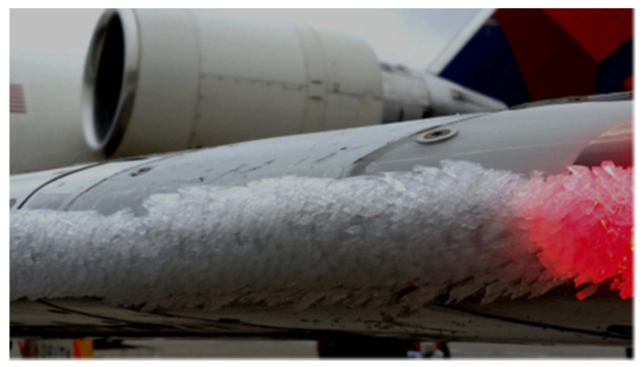
Figure 1.
Ice accretion on wing leading edge.
- Increased weight: Ice accumulation on an aircsraft's wings, tail, and other surfaces can increase its weight, which can affect its performance and fuel consumption;
- Reduced lift: Ice can change the shape of an aircraft's wings and reduce its ability to generate lift, which reduce the performance and make it harder to take off, climb, and maintain altitude.
- Increased drag: Ice can increase the drag on an aircraft's wings and other surfaces, which can reduce its speed and fuel efficiency.
- Risk of stall: the protrusions created by the ice formation can led to detachment of the boundary layer and so can induce a stall phenomenon. Furthermore stall warning system are designed to operate with clean airfoil. The profile change due to ice accumulation anticipates the stall effect without giving to pilot prodromal advices;
- Loss of control: Ice can affect an aircraft's control surfaces, such as the ailerons, elevators, and rudder, making it more difficult to maneuver and potentially leading to a loss of control.
- Engine problems: Ice can accumulate on an aircraft's engines, disrupting their airflow and potentially causing them to malfunction or stall.
- Reduced visibility/ Air Data corruption: Ice accumulation on an aircraft's windshield, windows, and air data sensors can reduce visibility and corrupt air data (pressure altitude, air speed, vertical speed) reducing the safety of the flight.
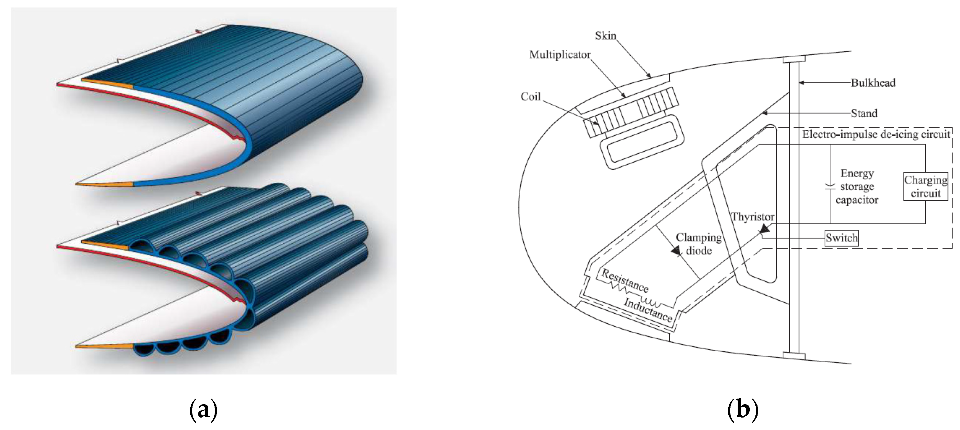
In order to permit safe flight into icing conditions anti-ice and de-ice system have been developed [16]. Deicing equipment are designed to remove formed ice using different methods; among the others the more commonly installed are pneumatically inflation of boots, thermal heating or by induced vibration in the leading edge. Deicing systems operates with a duty cycle automatically controlled. The low power required makes this equipment ideal for aircraft with low excess of power available like General Aviation or Commuters. For example surface deformation de-icing are the widely installed. These systems can use pneumatic boots [17] glued on the leading edge or Electro Magnetic Impulses (EIDI) [18].
Anti-icing comprises a different design philosophy: prevent icing formation instead of removing it periodically. Two approach are adopted among this family: running wet is the lowest power consuming, preheating the contact surface enough to prevent icing and full evaporative that vaporizes by contact the water droplet as soon as it gets in touch.
Different power source are used to pre heat the leading edge of the wing: electro thermal is one of the more adopted in more electric aircraft exploiting a conductive mesh embedded into the composite leading edge panel [20]. Copper meshes are widely used in helicopter blades [21] and for small surfaces such as Outside Air Temperature (OAT) probes or control surfaces. For larger surfaces to be anti-iced the widely system used is still the thermal pneumatic anti-ice. In this system, turbine compressor or heat exchangers with engine exhaust supplies hot air and then this air is delivered through pipes to the leading edges of the aircraft [22]. A schematic section of this system is reported in Figure 3. Different method are present at the same time on liner aircraft for different icing positions and devices. Table 1 reports briefly the most common technique applied in civil liners for different icing locations.
The novel solution, proposed by the authors [23,24], consist of a sandwich panel with a lattice core manufactured with laser bed powder fusion [25]. An artistic view is reported in Figure 4.
This novel solution permits to obtain several advantages:
- Thermal efficiency: air passage inside of the lattice core create a high turbulence that enhances the heat exchange. Moreover the punctual control over the lattice permits to customize the heat diffused where needed;
- System efficiency: integrating the system function inside of the structure permits an important weight saving;
- Reduction in construction and maintenance cost: the panel is recyclable and is a single piece plug and play without need of welding, joining or special gluing;
- Easy to rescale and manufacture: permits to install this system even in small scale aircraft or UAV with an enhancement in the flight safety and operability
This novel system permits to customize locally the heat flux in order to prevent icing formation or to melt ice already formed. For this reason is important to develop a tool that simulates accurately icing deposition and accretion and is able to integrate the local amount of heat required to have a running wet situation or a full evaporative solution.
2. Materials and Methods
Analytical or semi empirical methods are unlikely to capture the phenomenon of ice growth in detail. For this reason, numerical simulations have been developed capable of providing highly reliable predictions. Currently there are several codes developed by different countries:
In this paper, a novel ice formation model will be implemented using STAR-CCM + software. The novelty of this tool states in the capability to extrapolate the amount of heat needed to prevent ice forming. The choice of the software lies in the will, in the future, to make this part of the simulation dialogue autonomously with the internal flow tool in order to have a closed loop optimization.
Ice formation phenomenon is not stationary and depends mainly on the motion field, the collision of the aqueous particles, the boundary layer and the resolution of thermodynamic equations that govern solidification.
The amount of mass that solidifies can be expressed as the integral in time of the particles dispersed in a volume that impact on a surface A at a velocity v. The quantity of particles per unit of volume are reported as w, the volumetric concentration. This integral becomes:
However, this equation would require that all impacting particles solidify. This approximation, too coarse, can be corrected by inserting three terms: η1,2,3.
Collision efficiency is represented by η1; it has been observed that due to the different inertia, some particles in the collision trajectory do not impact, being transported by the aerodynamic current. This effect is governed by the relationship between the size of the average particle and the characteristic size of the body. Particles of small size do not interfere with large bodies but tend instead to accumulate on tapered surfaces, for example on the tip of the propeller blades.
The second efficiency η2 is characterized by the collection efficiency. This parameter permits to take into account the particles that collide with the aerodynamic profile but do not adhere to it. Super-cooled large droplets for example collide and flooding adhere perfectly. On the other hand, some particularly dry and icy snow formations tend to rebound after collision without increasing the ice layer on the profile.
The third and last useful term is the accretion efficiency. This value reports the post-impact of the particles. Due to the different latent heat, different icing effectiveness are observed: some drops of large dimensions can give rise to fluid slides that come out of the profile thus reducing the mass of ice in formation.
The formula 1 can thus be rewritten as [31]:
Ice growing, rime and glaze is reported in Figure 5
The mathematical exposition that follows is related to Glaze Ice due to its higher risk.
Solidification of liquid film due to balance of energy between air and drop of water can be expressed as:
Qlat reports the latent heat of the freezing particles of water, and can be expressed by:
The parameter λ represent the liquid fraction, Lf the specific latent heat and is the mass flow of the liquid portion of the air stream [32].
The second term reported in Equation 3 represent the kinetic energy lost during the impact. It is expressed as follow:
Third term is evaluated as Equation 4.
Last term evidences the heat lostdue to evaporation and it is given by:
Qcon represents the heat lost due to convection with air. It is function of ambient temperature T0 and surface temperature Ts; h is the convective heat transfer.
Last equation define Qsens and so the heat transferred because of the difference of temperature between airfoil surface and droplet. Td, in Equation 6 is the droplet water temperature.
The mass flow rate of the liquid phase. mw is connected with the Liquid Water Content (LWC) a, macroscopic parameter determined in meteorology. It is usually expressed in g/m3 and the usual value ranges from 0 to 0.6 [6]. Median Volumetric Diameter (MVD) states the average diameter of the droplet. Most critical situations occur with MVD ranges from 1.5 to 50 μm. Larger diameter are associated with glaze ice [33]; there is a relation between low LWC to evidence large MVD, reported in Figure 6. Larger droplets increases the collection efficiency since they are less affected by the aerodynamic flow and tend to contact the airfoil.
Temperature is also a macroscopic parameter that influences the type of ice formed on airfoils. If it is around 0°C it maintains longer the liquid state of the particles and so creates a glaze ice. Lower temperatures instead freezes immediately and product soft rime, as reported by Figure 7.
The CDF model followed three step: ice accretion model, anti-ice model and de-ice model.
2.1. Ice accretion model
Ice accretion model is time dependent, unsteady and is structured into 5 phases:
- Flow field resolution: external flow is solved through Navier Stokes Equations.
- Dispersed Phase: calculation of the trajectories of liquid phase is entered using Dispersed Multiphase Model (DMP) present in STAR CCM+.
- Fluid Film Resolution: evaluates the impacting particles and determines freezing or liquefaction by solving Conjugate heat Transfer (CHT) thermodynamic balance.
- Ice thickness calculation; identify the local thickness formed in step 3.
- Morphing: modify the flow grid subtracting the solidified ice from the air domain.
Dispersed Multiphase Model uses equations reported previously for both phase. The approach is identified as “one way”: the external flow can influence the liquid phase through heat and aerodynamic resistance but the latter cannot influence the gas phase.
The resolution of the fluid film is based on enthalpy. Enthalpy for the liquid solid transition film H*f is calculated as follows:
Where Hf is the sensible Enthalpy and represent the portion of transition film occupied by the liquid phase. Depends on the normalized temperature:
T* identify the normalize temperature, evaluated as follows:
Ice thickness growth is given by:
This model does not permit the reduction of the icing formed. Thought is impossible to simulate the deicing function but only the anti-icing as is. The
The magnitude of the ice formed reflect then in the morphing displacement for each phase:
K is called Solid Time Step Factor. Allows to widen if necessary the displacement magnitude obtaining an acceleration on the simulations.
2.1. Anti ice Model Setup
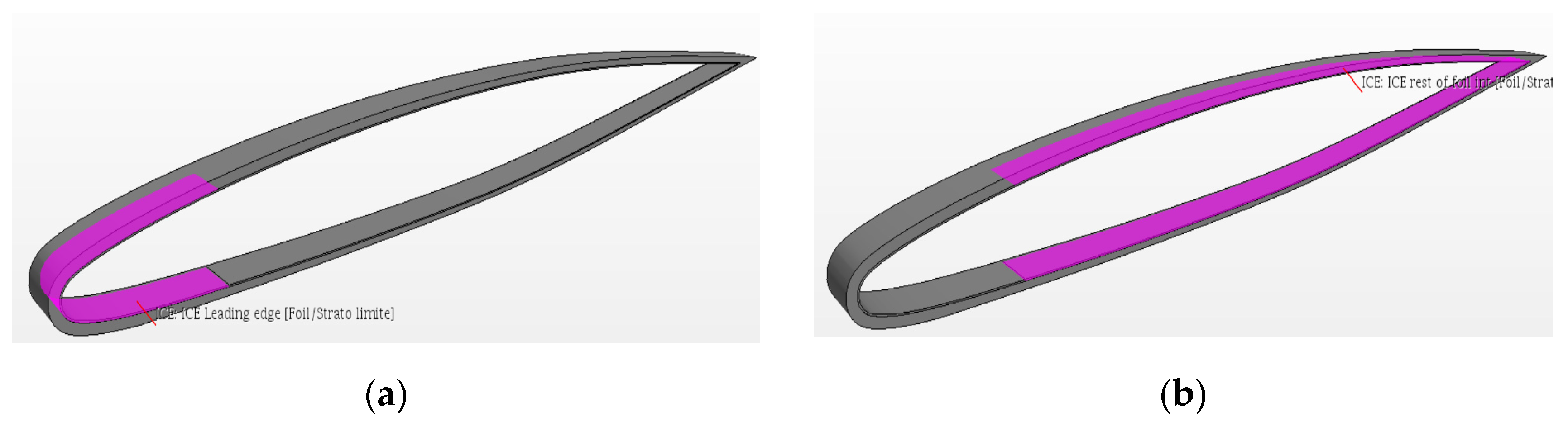
Anti-ice model has been implemented starting from ice accumulation model inserting some modifications. A metal solid part has been added, as reported in Figure 8 in purple.
Adding new metal part requires implementing a new heat exchange interface between metal profile and the shell with embedded the thin film model. The new schematization is reported in Figure 9.
Two local interface between 3D solid mesh and 2D shell mesh requires a perfect and stable correspondence between faces. To permit this correspondence to remain stable and persistent also during unsteady calculation the removal of the frozen film thickness has been disabled permanently.
2.2. De ice Model Setup
This model has the aim to evaluate the amount of time necessary to liquefy the ice deposited on the leading edge of the airfoil. Rather than being a deicing for in-flight operation this tool enable to evaluate the possibility to remove ice formed on the airfoil during pre-flight warm-up. The interest for this feature relies into the possibility to install the novel anti ice system on Unmanned Aerial Vehicles (UAV) operated from airfield with no supporting crew.
To simulate de-icing on ground a Volume of Fluid (VOF) has been adopted. An eulerian approach has been selected with a thermodynamic solidification and liquefaction model implemented. Material properties of liquid and solid phase are reported in Table 2.
The geometric part is comprises by a metallic airfoil with a superimposed layer of ice with pre-settled thickens. The airfoil has been divided in two parts to simulate the heated leading edge and non-heated back part.
Figure 10.
De-ice model setup: (a) Heated Part; (b) Non Heated Part.
The advantage of adopting VOF approach lies in the ease to the access at the concentration of the two phases. It is simple to observe the liquefaction in the front part and the enlargement to the rear half.
3. Results
This section will report the results collected from the model descripted in Section 2 Materials and Methods. In the first section the ice accretion model has been validated with NASA TP 2000-210031 Ice Accretion and Icing Effects for Modern Airfoils [10]; in the second section the result obtained for anti-icing will be discussed and in the third the result for the de-icing function.
3.1. Ice accretion model Validation
To validate the ice accretion model NASA Glenn Research Centre results were used [10]. FAR 25 appendix C conditions were considered. A Business Jet airfoil was chosen to be representative due to the similarity with the final application. The section of the profile is reported in Figure 11.
Five simulation have been used to compare the experimental evidences with the ice accretion simulations obtained by the model evaluation. This simulation differs for external airspeed, temperature, MVD Droplet, LWC and angle of attack. In this manner a uniform information on the performance of the model can be evaluated representative of different flight condition and different icing ambient. The property of the five tests are reported in Table 3.
The results collected are reported, graphically, in the graphs are showing the experimental point evaluated by NASA in red and the numerical simulation evaluated by Politecnico di Torino in Blue.
The results computed with the Ice Accretion Model are consistent with the data obtained by NASA. The lower camber line reports always a good correspondence with the experimental points in all test. The upper camber icing behavior replicates satisfactorily the experimental evidences with lower accretion time and lower angle of attack at high speed (i.e. Figure 12 a). Increasing the angle of attach it and reducing the airspeed it is possible to evidence some underestimation in Figure 12c; the estimation seems to reduce proportionally with the AOA as reported also in Figure 12d. overall, however, the model prediction are consistent with the experimental outcomes in shapes and magnitude in all the tests performed.
3.2. Anti icing Results
The model, validated in the ice formation and upgraded with the anti-icing feature has been tested with the conditions of Table 4 to evaluate if the heat flux imposed at the leading edge was sufficient for a running wet hypothesis.
The choice of temperature and speed has been imposed to match with experimental setup campaign conducted during winter 2022 on Aircraft.
Results obtained from the run are reported in Figure 13.
Figure 13 a represent the impingement rate, the particle of water that directly contact the surface. Due to the AOA of 6° the lower camber is the most affected with 0.033 kg/m2*s maximum. The same trend is confirmed by the second image, which reports the thickness of the fluid film, reaching a peak of 0.01mm in the lower camber. Figure 13c confirms that with the heat flux imposed there is no ice thickness accumulation on the leading edge, providing that the heat flux imposed is sufficient for a running wet anti-icing condition. After half of the chord the ice, tend to accumulate on both upper and lower profiles in minor entity. The last image reported evidences a high temperature on the leading edge (more than 9°C in le leading edge with a peak of 21.51 °C compared with the external flow temperature of -14.75°C. the upper profile, spanned by higher flow velocity presents lower temperature compared to the lower profile.
Figure 14 presents the upper and lower temperatures of the airfoil external profile varying the external air temperature. The curves present the same trend passing from -14°C (blue) to -6°C (green) and final to -2°C. it is interesting to evidence that the temperature curve remain unchanged in shape but only gets shifted upwards with towards higher temperatures.
3.3. De Icing Results
De-ice simulation is aimed to verify the possibility for the anti-icing system to remove formed ice. This task is intended to verify this possibility for the operation of UAV in airport without human personnel assistance. The same heat flow for anti-icing condition has been imposed with 5mm ice formed and a simulation time of 7 minutes.

Table 5.
De-icing conditions applied.
| Group | Parameters | Test Case |
|---|---|---|
| Aluminium | Static Temperature[°C] | -4 |
| Heat Flux [W/m2] | 1*104 | |
| Ice /Water | Water Density [kg/m3] | 997 |
| Ice Density [kg/m3] | 917 | |
| Water thermal conductivity [W/m*K] | 0.62 | |
| Ice thermal conductivity [W/m*K] | 2.33 | |
| Initial ice layer thickness[mm] | 5 |
Figure 15.
De Icing Results after 7 minutes: (a) Temperature Profile; (b) Solid Volume Fraction.
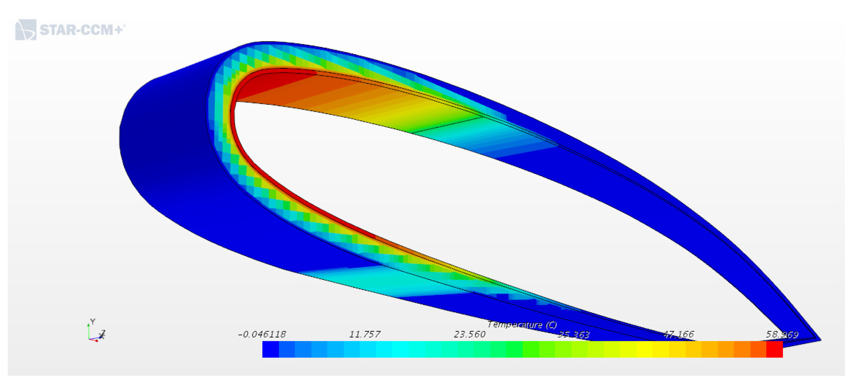
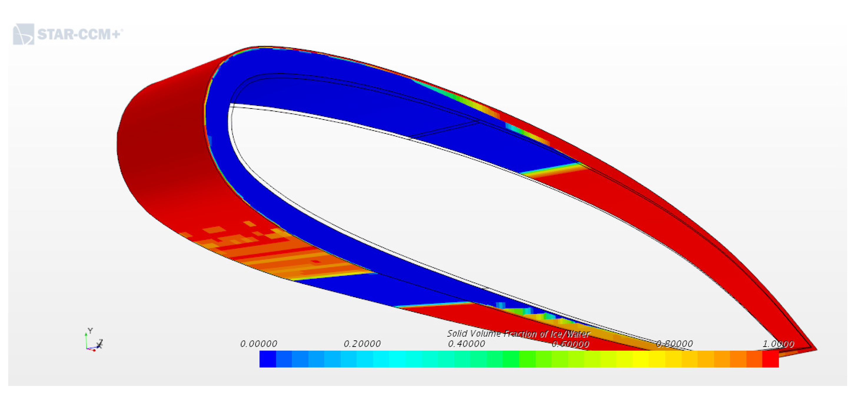
After 420 seconds, the temperature at the leading edge is around 58°C and the ice is liquefying on the correspondent area. Gradually, also the rear part is starting to melt, as evidenced by Figure 15b. These preliminary results reported is cautelative because it does not consider the fall down of ice part once the layer attaching to the airfoil is liquefied due to vibration and gravity.
5. Conclusions
The purpose of the current study was to present a novel, validated, icing model that is suitable also for anti-icing evaluations. The investigation has identified that the model is suitable to predict quantitatively and qualitatively icing phenomena on airfoil and is expandable to the anti-icing requests. The most important limitation lies in the fact that the anti-icing requires cross validation with experimental benches that are under construction at the moment. Further research should be undertaken to validate this aspects and to examine more closely the de-icing phenomena.
6. Patents
This work is part of the development of the patent of a novel anti-icing system for aircraft use [24]
Author Contributions
Conceptualization, Carlo Giovanni Ferro; methodology, , Carlo Giovanni Ferro; software, Carlo Giovanni Ferro and Daniele Champvillair; validation, Carlo Giovanni Ferro and Daniele Champvillair; formal analysis, Carlo Giovanni Ferro and Daniele Champvillair; investigation, Carlo Giovanni Ferro and Daniele Champvillair; resources, Paolo Maggiore; data curation, Carlo Giovanni Ferro; writing—original draft preparation, Carlo Giovanni Ferro; writing—review and editing, Carlo Giovanni Ferro; visualization, Paolo Maggiore; supervision, Paolo Maggiore; project administration, Paolo Maggiore; funding acquisition, Paolo Maggiore All authors have read and agreed to the published version of the manuscript.
Funding
This research received no external funding.
Conflicts of Interest
The authors declare no conflict of interest.
References
- NTSB, “Crash During Approach to Landing Empire Airlines Flight 8284,” 2009.
- NTSB, “Aircraft Accident Takeoff Stall in Icing Conditions of USAIR Flight 405,” 1992.
- NTSB, “NTSB Identification: CEN12FA152,” 2012.
- BEA, “Interim Report n ° 3 On the accident on 1st June 2009 to the Airbus A330-203 registered F-GZCP operated by Air France flight AF 447 Rio de Janeiro - Paris Bureau,” 2009.
- Y. Cao, Z. Wu, Y. Su, and Z. Xu, “Aircraft flight characteristics in icing conditions,” Progress in Aerospace Sciences, vol. 74. 2015. [CrossRef]
- S. G. Cober, G. A. Isaac, and J. W. Strapp, “Characterizations of Aircraft Icing Environments that Include Supercooled Large Drops,” J. Appl. Meteorol., vol. 40, no. 11, pp. 1984–2002, 2001. [CrossRef]
- M. B. Bragg, G. M. Gregorek, and J. D. Lee, “EXPERIMENTAL AND ANALYTICAL INVESTIGATIONS INTO AIRFOIL ICING.,” in Congress of the International Council of the Aeronautical Sciences, 1984, vol. 2.
- M. S. Virk, M. C. Homola, and P. J. Nicklasson, “Effect of rime ice accretion on aerodynamic characteristics of wind turbine blade profiles,” Wind Eng., vol. 34, no. 2, 2010. [CrossRef]
- M. B. BRAGG, “RIME ICE ACCRETION AND ITS EFFECT ON AIRFOIL PERFORMANCE,” The Ohio State University PP - United States -- Ohio, United States -- Ohio, 1981. [Online]. Available online: https://www.proquest.com/dissertations-theses/rime-ice-accretion-effect-on-airfoil-performance/docview/303170684/se-2?accountid=28840.
- H. E. Addy Jr., Ice Accretions and Icing Effects for Modern Airfoils, no. April. 2000.
- R. HANSMAN, JR., K. BREUER, D. HAZAN, A. REEHORST, and M. VARGAS, “Close-up analysis of aircraft ice accretion,” 1993. [CrossRef]
- W. Olsen and E. Walker, “EXPERIMENTAL EVIDENCE FOR MODIFYING THE CURRENT PHYSICAL MODEL FOR ICE ACCRETION ON AIRCRAFT SURFACES.,” 1986.
- Z. A. Janjua, B. Turnbull, S. Hibberd, and K. S. Choi, “Mixed ice accretion on aircraft wings,” Phys. Fluids, vol. 30, no. 2, 2018. [CrossRef]
- M. B. Bragg, T. Hutchison, J. Merret, R. Oltman, and D. Pohkariyal, “Effect of Ice Accretion on Aircraft Flight Dynamics University of Illinois at Urbana-Champaign,” 38th AIAA Aerosp. Sci. Meet. Exhib., 2000. [CrossRef]
- Y. Cao, W. Tan, and Z. Wu, “Aircraft icing: An ongoing threat to aviation safety,” Aerospace Science and Technology, vol. 75. 2018. [CrossRef]
- FAA, “Ice and Rain Protection,” Amt_Airframe_Handbook, no. July, pp. 570–582, 2011.
- Charles W Leguillon, “No Title,” US1942867A, 1932.
- X. Jiang and Y. Wang, “Studies on the electro-impulse de-icing system of aircraft,” Aerospace, vol. 6, no. 6, 2019. [CrossRef]
- L. Hao, Q. Li, W. Pan, and B. Li, “Icing detection and evaluation of the electro-impulse de-icing system based on infrared images processing,” Infrared Phys. Technol., vol. 109, 2020. [CrossRef]
- M. Mohseni and A. Amirfazli, “A novel electro-thermal anti-icing system for fiber-reinforced polymer composite airfoils,” Cold Reg. Sci. Technol., vol. 87, 2013. [CrossRef]
- H. J. Coffman, “HELICOPTER ROTOR ICING PROTECTION METHODS.,” J. Am. Helicopter Soc., vol. 32, no. 2, 1987. [CrossRef]
- C. J. Johnson, “Anti Icing Duct,”. US Patent 2320870, 1943.
- P. Maggiore, Fabio Vitti, C. G. Ferro, and Varetti Sara, “Thermal anti ice system integrated in the structure and method for its fabrication,” 102016000098196, 2016.
- P. M. Carlo Giovanni Ferro, Sara Varetti, Fabio Vitti, “Thermal anti ice system integrated in the structure and method for its fabrication,” 102016000098196, 2016.
- C. Ferro et al., “A Robust Multifunctional Sandwich Panel Design with Trabecular Structures by the Use of Additive Manufacturing Technology for a New De-Icing System,” Technologies, vol. 5, no. 2, p. 35, 2017. [CrossRef]
- G. a. Ruff and B. M. Berkowitz, “Users manual for the improved NASA Lewis ice accretion code LEWICE 1.6,” 1990.
- Y. B. H. B. W. G. Habashi, “Development of a Shallow-Water Icing Model in FENSAP-ICE,” J. Aircr., vol. 37, pp. 640–646, 2000. [CrossRef]
- RAE TR 90054, “ONERA three-dimensional icing model,” AIAA, 1995.
- R. T. E. Iuliano, V. Brandi, G. Mingione, C. de Nicola, “Water impingement prediction on multi-element airfoils by means of Eulerian and Lagrangian approach with viscous and inviscid air flow,” AIAA Aerosp. Sci. Meet. Exhib. [CrossRef]
- R.W. Gent, “TRAJICE2–A combined water droplet trajectory and ice accretion prediction program for aerofoils,” RAE TR 90054, 1990.
- K. Mortensen, “CFD Simulations of an Airfoil With Leading Edge Ice Accretion,” no. August, pp. 1–117, 2008.
- L. Makkonen, “Models for the growth of rime, glaze, icicles and wet snow on structures,” Philos. Trans. R. Soc. A Math. Phys. Eng. Sci., vol. 358, no. 1776, pp. 2913–2939, 2000. [CrossRef]
- Ackley and M.K Templeton, “Computer Modeling of Atmospheric Ice Accretion,” 1979.
- D. Champvillair, “Numerical and experimental validation of an innovative anti ice panel by means of computational fluid dynamics,” 2018.
Figure 3.
Hot Air Anti Ice schematic section.
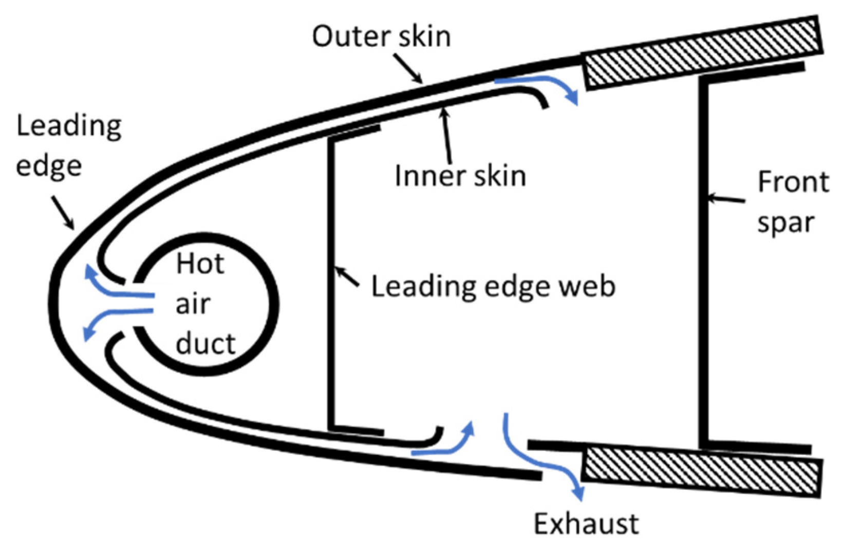
Figure 4.
Section View of the multifunctional panel.
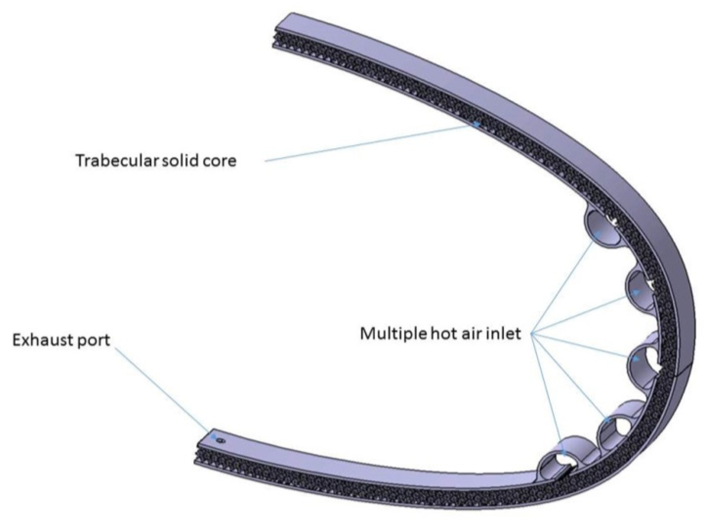
Figure 5.
Ice growing (a) Rime Ice; (b) Glaze Ice.
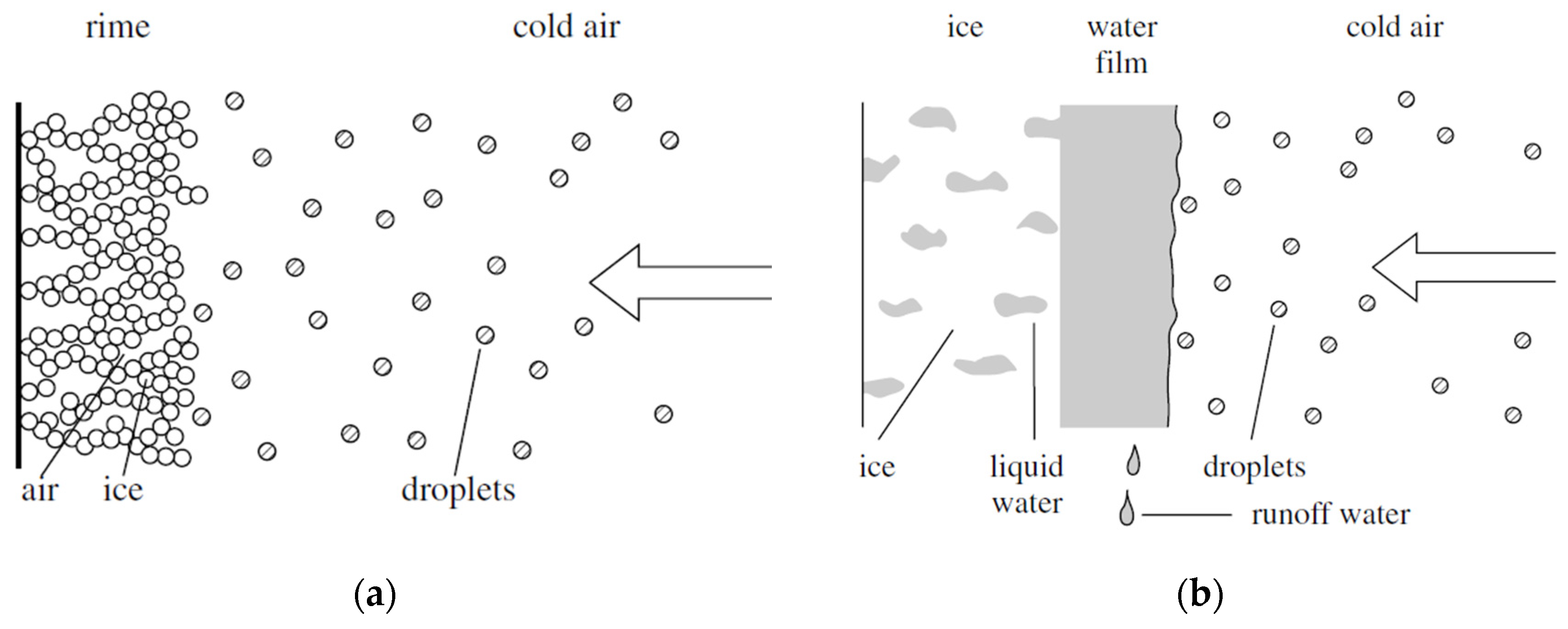
Figure 6.
Relation between LWC and MVD for different temperatures [6].
Figure 6.
Relation between LWC and MVD for different temperatures [6].
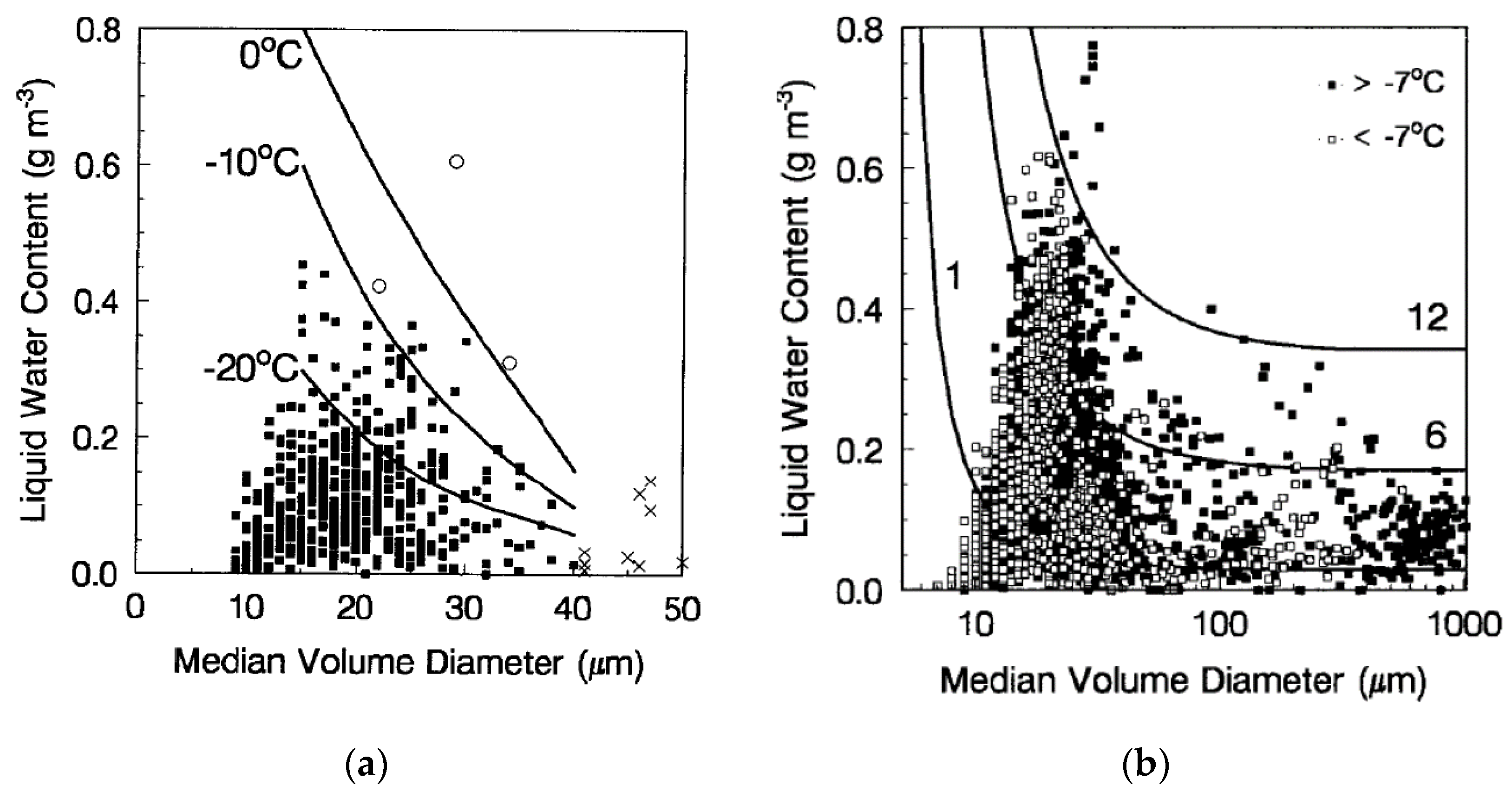
Figure 7.
Ice type vs Temperature and Wind Speed [6].
Figure 7.
Ice type vs Temperature and Wind Speed [6].
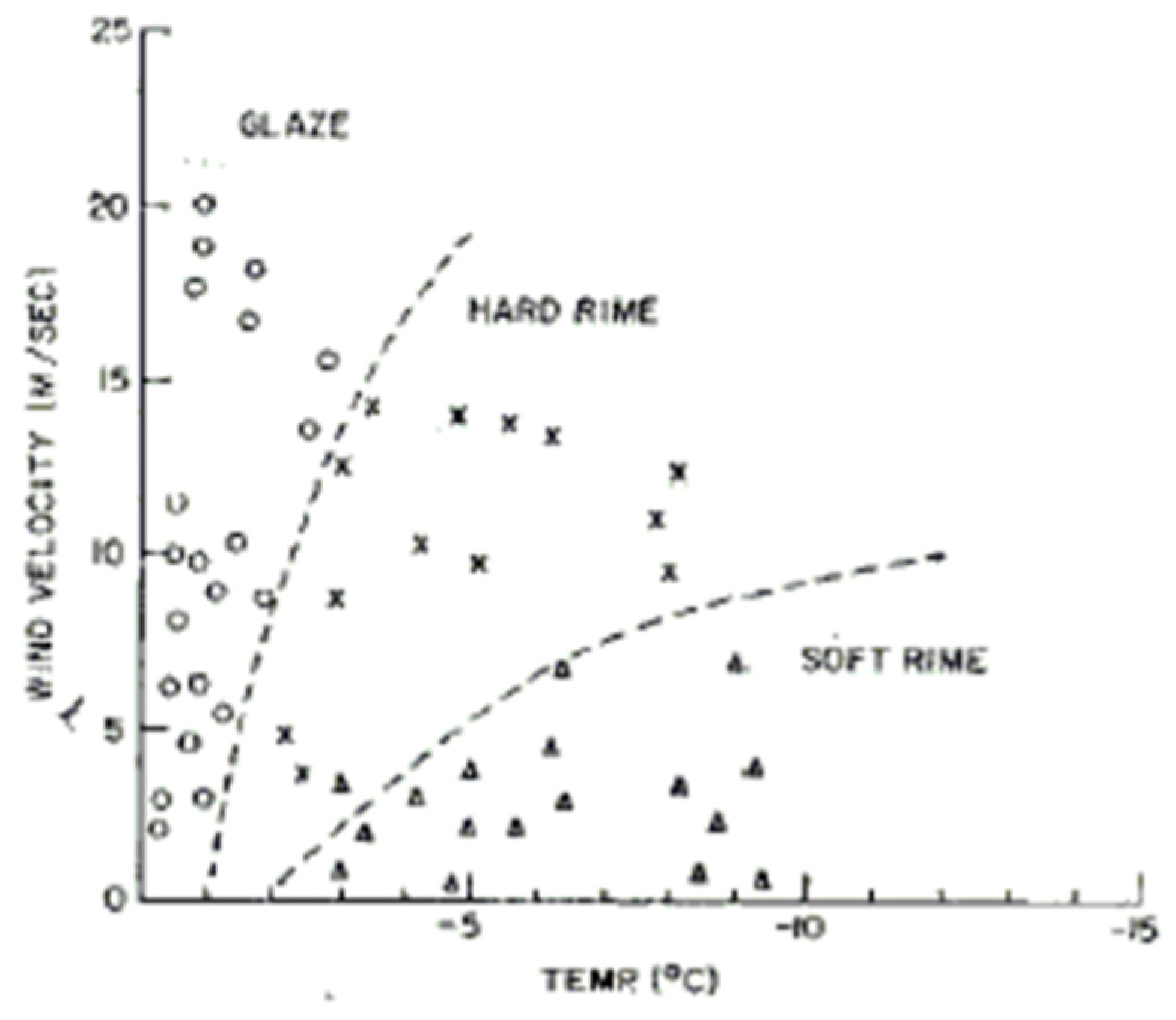
Figure 8.
New metallic part (pink) added to simulate the airfoil.
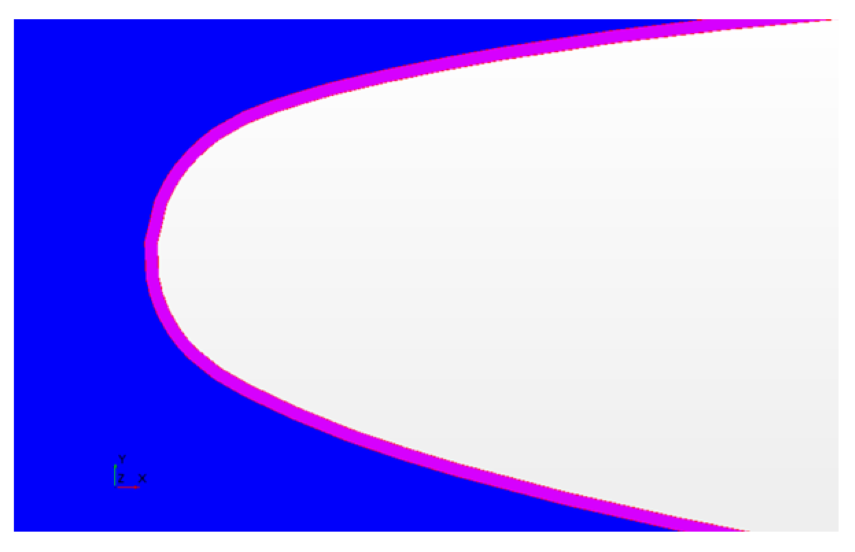
Figure 9.
View of the new model [34].
Figure 9.
View of the new model [34].
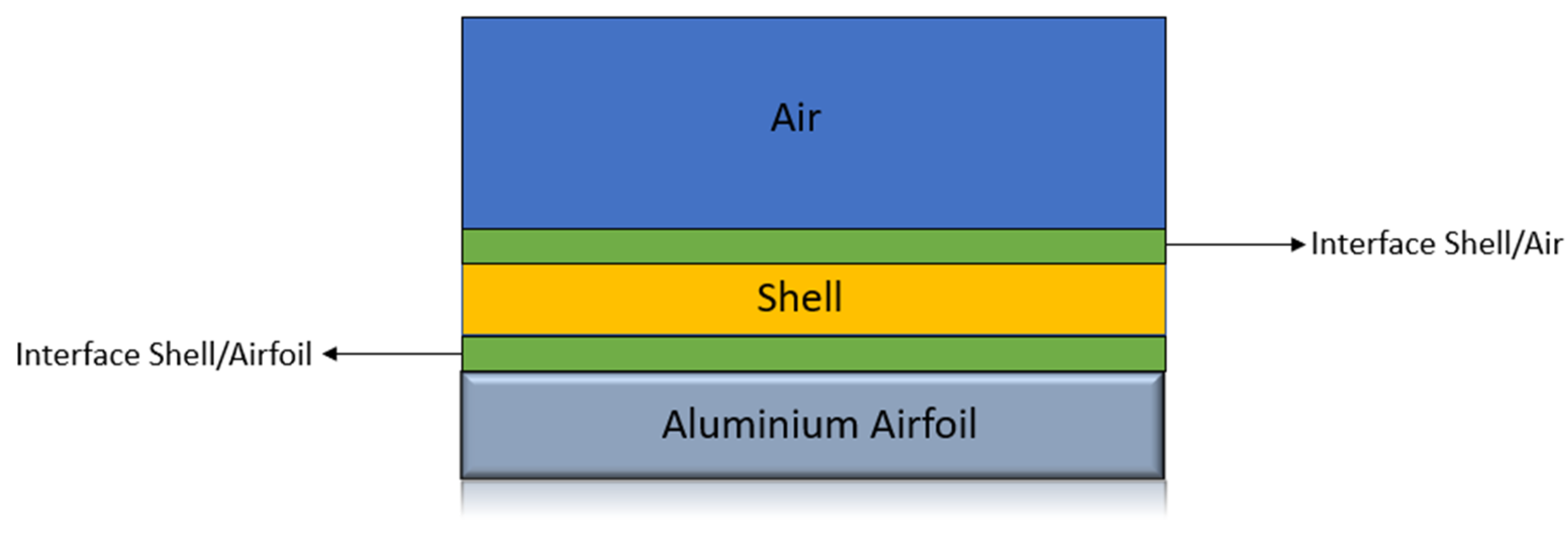
Figure 11.
Business Jet Airfoil.
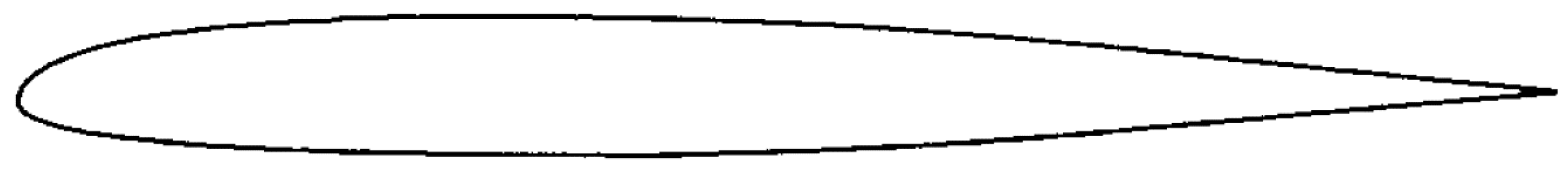
Figure 12.
Model Validation Comparison: (a) Test Case A; (b) Test Case B; (c) Test Case C; (d) Test Case D; (e) Test Case E.
Figure 12.
Model Validation Comparison: (a) Test Case A; (b) Test Case B; (c) Test Case C; (d) Test Case D; (e) Test Case E.
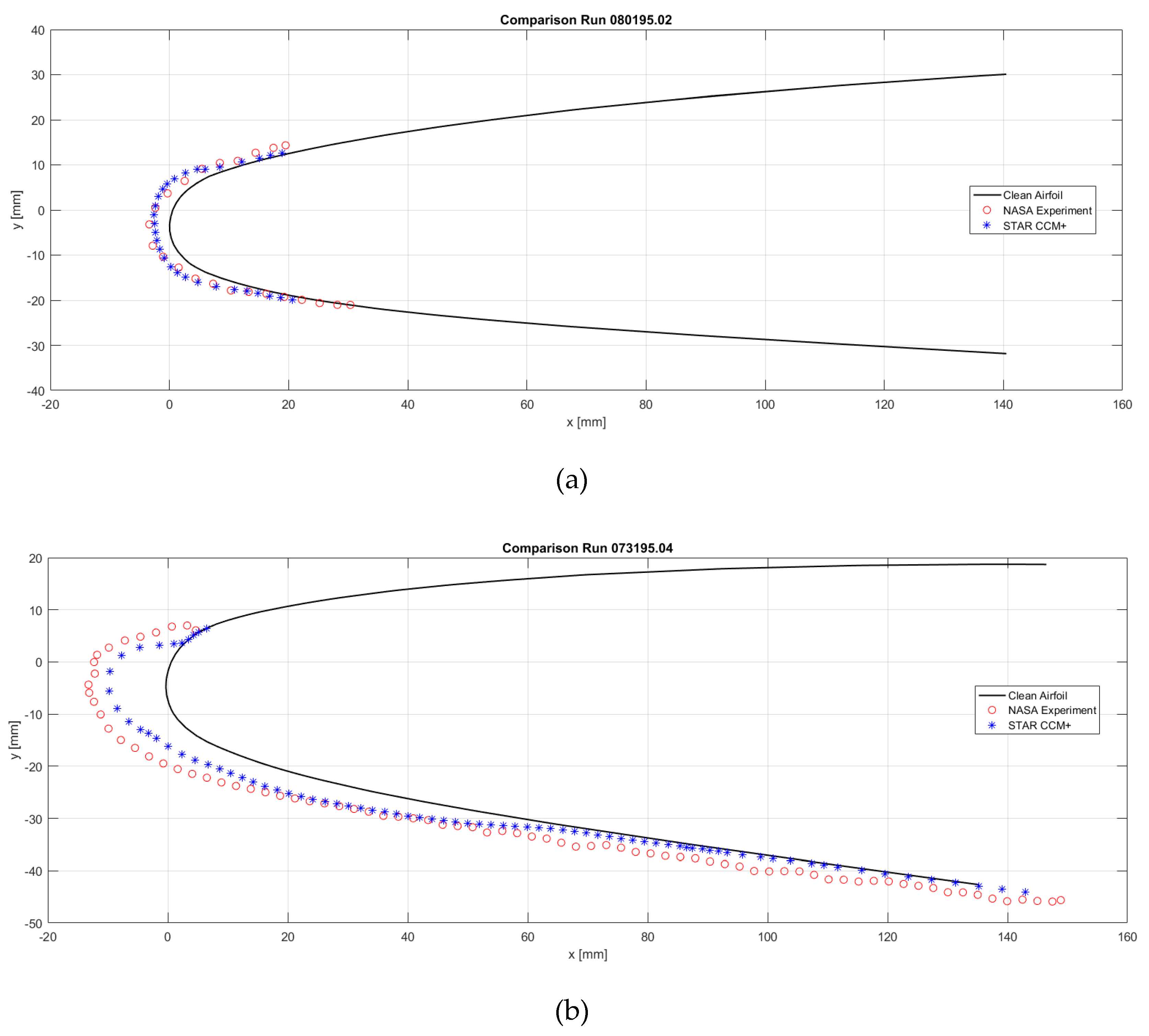
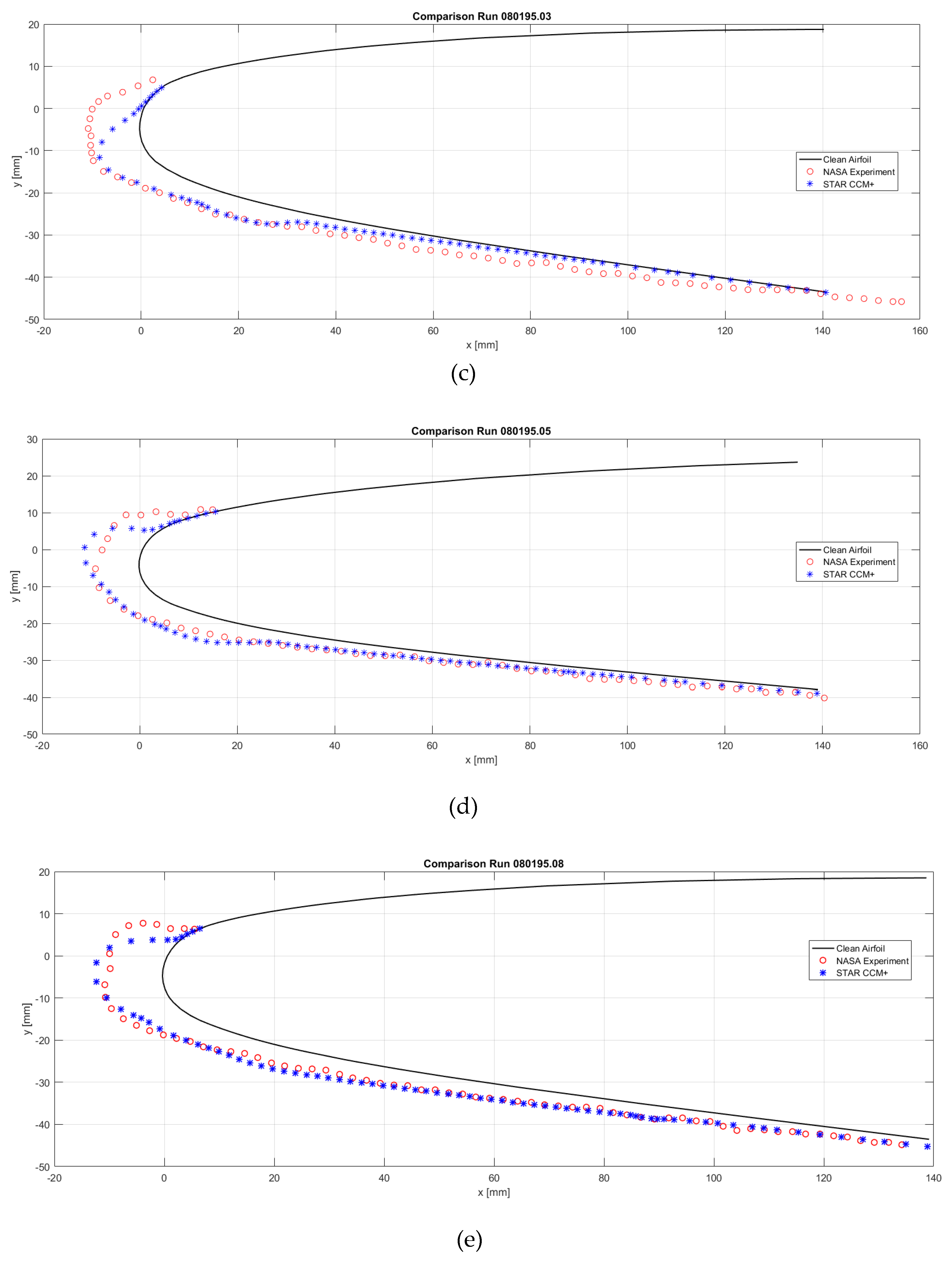
Figure 13.
Anti Icing Results: (a) Impingement Rate; (b) Fluid Film; (c) Solid Film Thickness; (d) Temperature of the Airfoil.
Figure 13.
Anti Icing Results: (a) Impingement Rate; (b) Fluid Film; (c) Solid Film Thickness; (d) Temperature of the Airfoil.
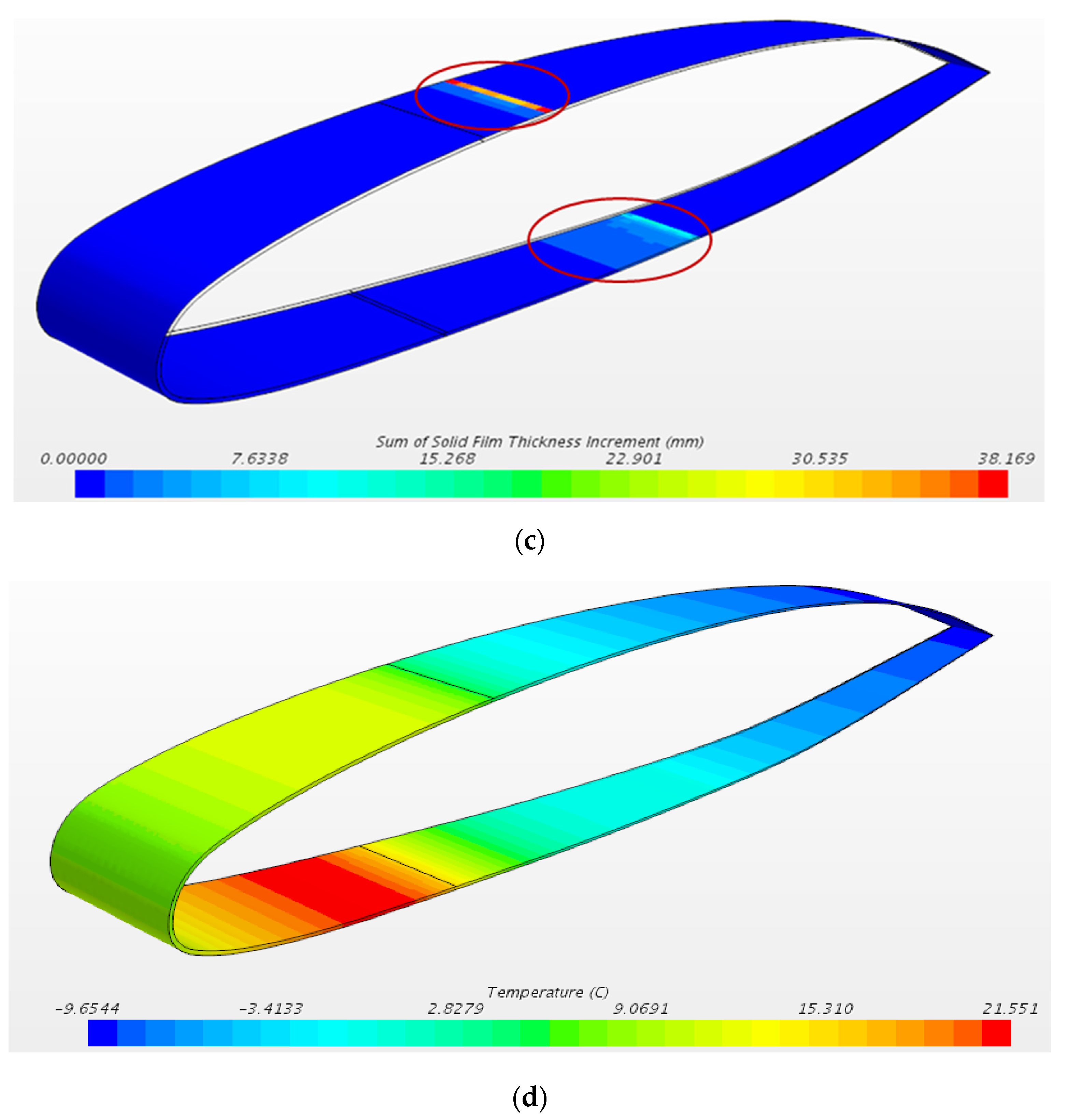
Figure 14.
Temperature profiles with different external air temperature.
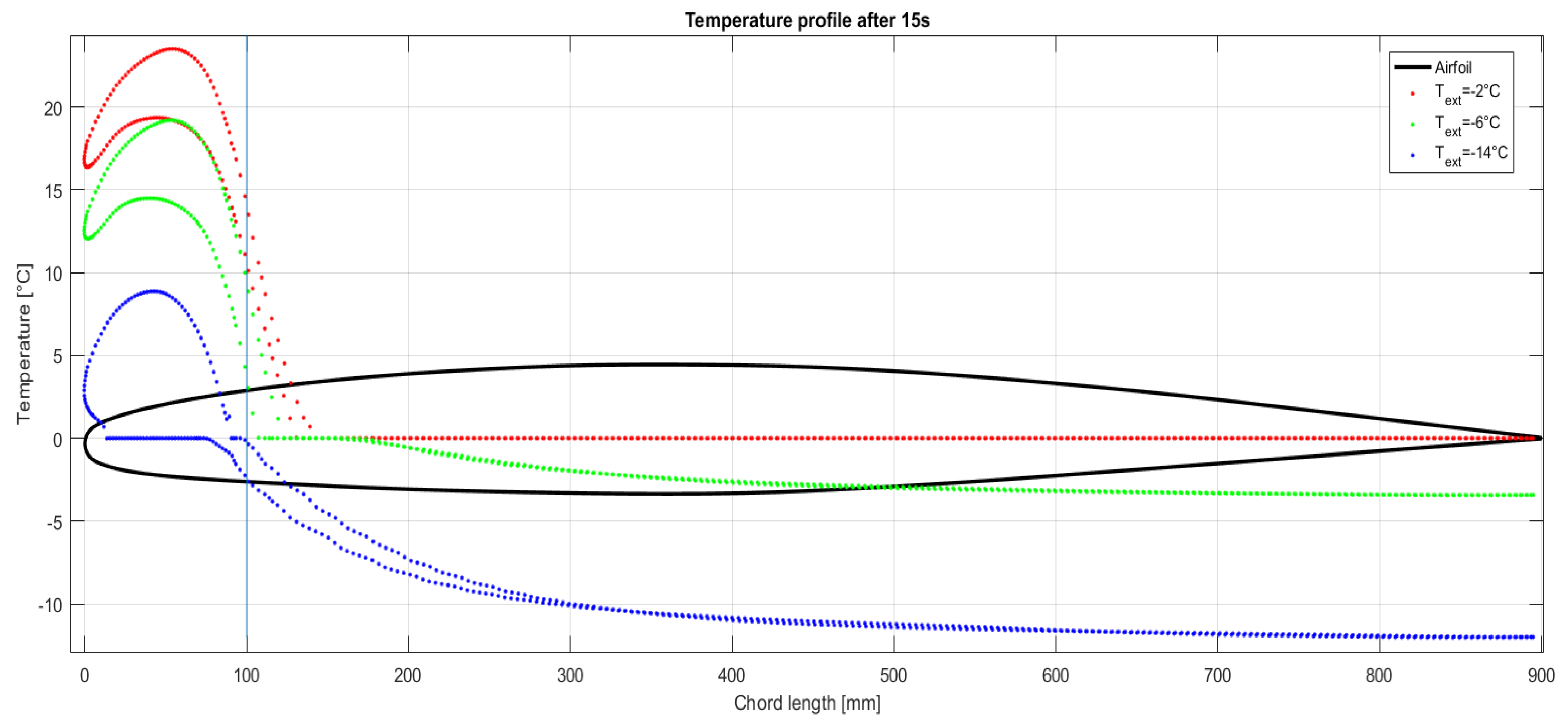
Table 1.
Ice location and typical control mode.
| Ice Location | Control Method |
|---|---|
| Leading edge of wing | Thermal pneumatic, thermal electric, chemical and pneumatic (deice) |
| Leading edges of vertical and horizontal stabilizers |
Thermal pneumatic, thermal electric and pneumatic (deice) |
| Windshield, windows | Thermal pneumatic, thermal electric and chemical |
| Heater and engine air inlets | Thermal pneumatic and thermal electric |
| Pitot and static air data sensors | Thermal electric |
| Propeller blade leading edge and spinner | Thermal electric and chemical |
| Carburetors | Thermal pneumatic and chemical |
| Lavatory drains and portable water lines | Thermal electric |
Table 2.
Fluid properties of Liquid and Solid Phases.
| Material Properties | ||
|---|---|---|
| Range temperature | Density | Thermal Conductivity |
| T > 273.15 K (Water) | 917 kg/m3 | 0.620 W/mK |
| T < 273.15 K (Ice) | 997 kg/m3 | 2.330 W/mK |
Table 3.
Model Validation Input Data.
| Group | Parameters | Simulations Test Cases | ||||
|---|---|---|---|---|---|---|
| A | B | C | D | E | ||
| External Flow | Velocity [m/s] | 129 | 90 | 90 | 90 | 90 |
| Temperature [°C] | -20 | -15 | -18 | -18 | -18 | |
| Dispersed Phase | MVD [µm] | 40 | 20 | 20 | 40 | 40 |
| LWC [g/m3] | 0.41 | 0.54 | 0.53 | 0.53 | 0.53 | |
| Airfoil | AOA | 1.5 | 6.1 | 6.1 | 4 | 6.2 |
| Ice Accretion Time [min] | 1.5 | 6 | 6 | 6 | 6 | |
Table 4.
Anti-icing conditions applied.
| Group | Parameters | Test Case |
|---|---|---|
| External Flow | Velocity [m/s] | 90 |
| Temperature [°C] | -14.75 | |
| Dispersed Phase | MVD [µm] | 20 |
| LWC [g/m3] | 0.54 | |
| Airfoil | AOA | 6.1 |
| Ice Accretion Time [min] | 1.5 | |
| Leading Edge Heat Flux [W/m2] | 1*104 | |
Disclaimer/Publisher’s Note: The statements, opinions and data contained in all publications are solely those of the individual author(s) and contributor(s) and not of MDPI and/or the editor(s). MDPI and/or the editor(s) disclaim responsibility for any injury to people or property resulting from any ideas, methods, instructions or products referred to in the content. |
© 2023 by the authors. Licensee MDPI, Basel, Switzerland. This article is an open access article distributed under the terms and conditions of the Creative Commons Attribution (CC BY) license (http://creativecommons.org/licenses/by/4.0/).
Copyright: This open access article is published under a Creative Commons CC BY 4.0 license, which permit the free download, distribution, and reuse, provided that the author and preprint are cited in any reuse.


