

Submitted:
07 January 2023
Posted:
11 January 2023
You are already at the latest version
Abstract
Object of this work is the design and the simulation of a hybrid UAV with VTOL capabilities that has been designed for landing on naval moving platforms. The work is focused on the innovative propulsion layout adopted on the UAV. Authors discuss how adopted low level control strategies can exploit the innovative features of the proposed system assuring a good rejection of transversal wind disturbances. Particular attention is dedicated to low level modelling and control of the system emphasizing how choices regarding low level actuation and control should improve performances and robustness of the system.
Keywords:
Unmanned Aerial Vehicles
; Vertical Take Off and Landing
; Robust Control
; Hybrid Propulsion of Aerial Vehicles
; Sliding Mode Control
List of Adopted Symbols
| ψ | heading angle (ψid is the ideal path value, ψref the reference one) |
| χ | course angle (χr is the course error) |
| Vg | ground speed |
| W | wind speed |
| Va | speed respect to air |
| α | heading direction from current plane position to the next waypoint |
| δ | error between α and ψid |
| kh | gain of the heading controller |
| satij(x) | saturation function (saturates x between a min. value i and a max. one j) |
| d | transversal position error |
| s | sliding mode variable defined as the sum of contributions s1, s2 |
| k1 | calibration variable of sliding mode controller |
| k2 | gain of the sliding mode feedback |
| R | curvature radius |
| ϕ,θ | roll and pitch angles (ϕid,θid desired values) |
| h,hid | altitude and desired altitude |
| p,q,r | angular speed along the three directions |
| m, g | mass and grav.acceleration |
| Ttot | total prop. force respect to a fixed ref. (Ttot_i is the ith component) |
| Mtot | total prop. torque respect to a fixed ref. (Mtot_i is the ith component) |
| Ti | thrust of the ith propeller |
| xbody | longitudinal axis aligned to vehicle heading |
| x,y | position along x and y axis(xid,yid are desired values) |
| τi | forces along i-th direction in body reference frame (τri are the torques) |
| a, b1, b2 | dimensions describing the position of propellers |
| kti,kqi | thrust(pedex t) and torque(pedex q) coefficients of the i-th propeller |
| xs, vs | position and sailing speed of the support ship/moving landing platform |
| xi,hi | desired positions and altitudes corresponding to different waypoints |
1. Introduction:
The object of this work is an innovative propulsion layout for an UAV with VTOL (Vertical Take Off and Landing) capabilities and the way in which adopted path following control can contribute to exploit the performances of the proposed system.
Proposed system is mainly devoted for marine operations [1] involving the usage of ship-based helipads, this is an application that is still the object of very recent studies [2] for its relevant industrial interest.
The study is applied to propulsion and path control of a real industrial product[3] with a relevant impact also on specialized technical media [4,5,6].
Propulsion layouts of UAV can be classified according to the way in which lift and propulsion are generated following a classification that is often adopted by review papers in literature [7]:
- Lighter than air UAVs (Airships, Dirigibles, Blimps and Balloons): the mean density of the vehicle is equal or lower respect to surrounding air, so lift forces are automatically granted. These kinds of vehicles are still proposed in recent works [8] since they offer the best ratio between lifted load and consumed energy. Additional propellers can be used control vehicle path. However, their low density also involves a higher sensitivity to crosswinds, also limiting maximum cruising speed.
- Rotary/Rotating Wing Systems: in a rotating wing system weight of the UAV is sustained by the efforts developed propellers that are consequently vertical or slightly inclined. UAV can perform VTOL and hoovering, maneuverability at low speed is excellent [9]. Known drawbacks are the poor propulsion efficiency (large part of installed power is employed to sustain the weight of the drone) and consequently limited autonomy and poor performances with harsh environmental conditions. Since propellers are vertical, longitudinal, or transversal propulsion efforts can be obtained only producing a corresponding pitch or roll rotation of the hull vehicle, so the control of the pose cannot be completely decoupled respect to translational motion [10].
- Fixed Wing Systems: In fixed wing systems lift is caused by the vehicle speed through the interaction of wings or other aerodynamic surfaces with the incoming flux of air. Propellers are used only to provide the longitudinal thrust against drag forces due to motion. Lift provided by wings is typically ten to twenty times higher respect to drag resistances [11]. Propulsion efficiency and autonomy are much higher respect to a rotating wing solution. Cruising velocity cannot be lower than stall speed precluding VTOL capabilities. Fixed wing drones often adopt catapults [12] for takeoff or landing nets or hooks for landing [13].
In this work this last solution [16] is adopted. A similar layout is also adopted for overcited marine applications involving the landing on a ship deck [1]. As shown in Figure 1 and Table 1, proposed propulsion layouts introduce some distinctive innovations respect to the work of Dundar[12] since proposed system is not pure electric but hybrid: an ICE (Internal Combustion Engine moves a rear propeller that provides the longitudinal thrust during fixed wing cruising. This choice was preferred to maximize autonomy since fossil fuels are still the lightest way to store energy on an aerial system; a direct mechanical connection of the propeller with ICE involves a high propulsion efficiency as verified by past studies of the same authors [17]. The ICE is connected to an alternator that recharge batteries sustaining all the electrical loads of the UAV. The alternator is controlled by a four-quadrant drive: the same electrical machine can be used to boost the performances of the rear propeller realizing a parallel hybrid system [18,19] that exploits energy stored in batteries. All the other propellers are driven by electric motors feed by batteries: an additional longitudinal electric propeller is placed in the front of the vehicle; eight vertical propellers sustain UAV weight during rotating wing propulsion. Adopted full-electric/hybrid-series configuration [19] is not efficient as the direct mechanical connection of the rear propeller, but it allows an easier coordination of multiple vertical and horizontal propellers during VTOL maneuvers when the UAV is working as a rotating wing drone.
Ailerons and ruddervators are used to control vehicle path during fixed wing cruising.
To better exploit the performances of the proposed layout, authors investigate how different path control algorithms can improve vehicle performances especially against crosswind disturbances both in fixed wing cruising or during VTOL operations when rotating wing mode is activated.
In particular for what concern the fixed wing mode there is a wide literature[20,21] concerning the way in which path following can be implemented distinguishing among the following approaches:
- Control Methods: these methods are designed to assure the convergence of cross track error of the UAV while maintaining a preset airspeed. To the latter category for example belongs the Vector Field (VF) technique[24,25], which involves designing a vector field to guide the aircraft on the desired path even in the presence of a constant wind disturbance.
A Further distinction[23] can be made distinguishing between look ahead [26], Non-Linear Guidance Law (NLGL) [27], Pure Pursuit and Line of-Sight (PLOS)[28] methods. However comparisons performed by the same literature sources [22,23] confirm the general suitability of vector field techniques against constant crosswind disturbances and their overall robustness and performance in terms of maintaining stable paths with relatively efficient and smooth behavior in terms of performed actuations/corrections.
In this work, authors adopted for fixed wing cruising a vector field control based on the SMC approach (Sliding Mode Control)[29,30]. Adoption of a sliding mode control has been recently proposed in literature for path control of fixed wing drones[31]. However, most of the over cited works in literature focused their attention on the control of the heading angle of the plane (whose definition will be cleared in the following section of this work), while the SMC proposed in this work is focused on the control of the course angle introducing a further improvement that is useful for the rejection of the crosswind disturbances.
Another innovative contribution of this work is represented by the path following control proposed in this work during the VTOL phase while the vehicle is operating in rotating wing mode. Conventional rotating wing UAVs are controlled during VTOL using only vertical propellers[32], in this sense there is a plenty of work in literature in which this approach is applied and its further improved by adopting different approaches aiming to improve the robustness of adopted control respect to unmodelled dynamics [33] or to improve the modelling of the controlled UAV through identification procedures[34]. Both these approaches are suboptimal respect to the control of UAVs with hybrid mixed propulsion layouts as the one proposed in this work: mixed propulsion layouts involve the presence of wings and of additional longitudinal propellers.
The presence of wing involves a higher and anisotropic sensitivity against crosswinds that should be further increased by roll and pitch rotations that are normally performed to control transversal and longitudinal efforts of rotating wing drones. Otherwise the presence of longitudinal propeller can provide an additional longitudinal effort that is quite fundamental to assure UAV stability against crosswind.
For this reason, the authors propose in this work a “directional VTOL” control which is specifically designed for this kind of vehicles: pose of the vehicle is kept constant to avoid additional disturbances, longitudinal propellers are exploited to cause vehicle motion and the vehicle is kept aligned along a position error direction to both exploit longitudinal propeller and to optimize the aerodynamic behavior of the plane respect to incoming flux of air. Also this approach is quite innovative respect to current literature because the way in which path control is performed during VTOL operations is specifically designed for known features of the proposed hybrid, mixed propulsion layout. Also this kind of control is much more similar to heading/course control performed during fixed wing cruising simplifying the transition between the two modes during take-off or landing maneuvers.
Finally, for Directional VTOL desired efforts are allocated on propellers with a model based approach that calculate desired speed references for each propeller from desire thrusts and torques. Also this approach is quite more refined respect to allocation criteria that conventionally adopted on drones since model based allocation according thruster model is more commonly adopted in recent studies[35,36] concerning the control of AUVs (Autonomous Underwater Vehicles).
1.1. Innovative Contributions
Innovative contributions of this research work can be summarized in the following points:
- A redundant hybrid and mixed propulsion layout is proposed for the design of an innovative UAV with VTOL capabilities
- Performances in crusing/fixed wing mode are improved adopting an SMC control of the course angle.
- During VTOL operations the vehicle is controlled with a specific controller able to better exploit vehicle features respect to conventional approaches followed on quad rotors.
- Allocation of speed references for the ESCs (Electronic Speed Controls) of each propeller is performed considering its torque and thrust coefficients, accelerating both calibration and scaling of the system.
1.2. Structure of the Paper
Proposed work is organized in the following way:
- UAV Modelling: a brief section introducing the adopted model of UAV
- Innovative SMC Path Control: a section related to the description of the proposed SMC control for fixed wing mode.
- Innovative directional VTOL Control: proposed directional control adopted for VTOL operation is shown
- Simulation Results: an extended simulation campaign is performed to show main features of proposed control strategies respect to the benchmark test UAV.
- Conclusions and Future Developments
2. UAV Modelling
Investigated UAV described in Figure 1 and Table 1 is modelled using a complete model that has been described in a previous publication[37] in which the UNIFI simulation platform that is used in this work was defined and described. Respect to this previous work, current propulsion layout has a higher number of both vertical propellers (eight instead of four) and longitudinal propellers (two instead of four) to assure a higher level of redundancy required by marine/naval operations:
- VTOL is possible with 75% of availability of vertical propellers (2 faulted propellers).
- Fixed wing propulsion can be assured by a single longitudinal propeller (the front or the rear one).
A scheme of the complete Matlab-Simulink™ model of the UAV is described in Figure 2/a.
The model is designed to allow a multi-thread implementation for sub-systems representing the behavior of continuous physical systems respect to discrete/digital systems corresponding as example to the navigation and control logic of the vehicle.
Discrete systems are implemented considering their known sampling frequency (from 10 to 250Hz).
For continuous/physical systems the integration must be conversely higher: if the model is used only for simulation purposes a robust variable step solver (Ode 23tb a “stiff solver”) is adopted. For real time implementation a fixed step solver (Ode 1/Euler) running at higher frequency (1000Hz) is chosen. In this way the same model can be used also for RT (Real Time applications), such as HIL & SIL testing [38].
The Following sub-models, as shown in Figure 2/a are implemented:
- Mechanical Model of the UAV: UAV dynamics is calculated according to a multibody model [39] that take count of propeller thrusts, and aerodynamic forces due to the incoming flow of air adopting corresponding matrices of linearized coefficients representing inertial and viscous effects. Followed approach is substantially based on the one that has been proposed by Fossen for both aerial[26] and marine[40] autonomous vehicles. Modelled UAV shares almost the same aerodynamics with a pre-existing UAV, the rapier X-25[41] which have only one longitudinal propeller. So main data concerning aerodynamics are available from previous experiences. In proposed AUV propellers are changed respect to the original X-25 project, so authors verified experimentally the target data of motors [42] and propellers [43] with laboratory tests that are shown in Figure 2/b and in Table 2: propeller; motor and driver are assembled with load sensors (phase 1), aerodynamic covers are placed (phase 2) than propeller invested by a controlled flux of air is tested (phase 3). Finally, experimental results, as shown in Table 2, are compared with data declared by the builder of the propellers also considering the variability of air density respect to altitude [44]: obtained experimental results are slight different but measured performances in terms of thrust are better than expected so a safety of about 10% is assured.
- Energy Management: All the loads on the UAV (actuators propellers, auxiliaries etc.) are simulated. Simulated hybrid power management system is described by a past research work of authors[17].
- Sensors: all the measured/estimated states of the system are evaluated through sensors sub models. For this work, it was preferred the hypothesis of a perfect estimation of system state (ideal sensors).
- Control: the UAV is controlled by a three level nested architecture often proposed in literature[46], that is implemented using Stateflow™. The top level of the control is represented by Path Planning that has been previously described in [37] and it’s not the object of the current work. The respect of the path decided by the Path Planning is assured by an inner/nested loop, the so called Path Following Control which decide how to correct route of the vehicle. Desired path corrections involve the Allocation of corresponding control references for propellers and actuators. This work is mainly focused on the two inner loops (Path Following and Allocation).
- Safety Management: safety protections and failure mitigation policies are modelled in this sub-model.
Resulting model can simulate different propulsion modes and the transition between them during a typical mission profile which is shown in Figure 3: proposed UAV can perform VTOL using only vertical propellers as a standard octocopter [47]. As the UAV reaches an assigned altitude, transition from VTOL to fixed wing mode and vice versa can be performed using transition methods proposed in literature [48]. Respect to full electric systems [16], autonomy in fixed wing mode is much higher since the rear propeller is directly connected to the ICE. The innovative directional VTOL Control proposed in this work is mainly designed for a more efficient landing on a moving ship deck. For this work, it is supposed as landing deck an Italian ship [49] performing a straight cruise with a constant maximum speed of no more than 10m/s (about 20knots). Landing is performed with a straight trajectory aligned to the stern of the ship.
3. Innovative SMC Path Control
Most of Path following controls proposed in literature for fixed wing cruising perform a feedback control of the heading angle ψ. As shown in Figure 4, ψ is defined as the angle that describe the geometric orientation of the plane respect to North in a fixed reference frame.
The course angle χ defines the direction of Vg, the ground speed of the UAV. Vg is the absolute speed of the plane which can be decomposed in two components: W is the wind velocity (the velocity of the air) and Va is the velocity respect to air.
The control that was previously implemented [50] on the drone was described by equation (1) and by the scheme of Figure 5/a.
The angle α describes the orientation of the segment that connect the current UAV position with the next waypoint. ψid is the ideal heading direction of the minimal distance between successive waypoints. δ is defined as the error between α and ψid . The plane is controlled by imposing a reference heading angle e ψref (1) equal to the sum of ψid and a feedback term proportional (gain kh) to the angular error δ; to avoid excessive corrections the feedback terms is saturated to a maximum value equal to π/4 (sat is the saturation function). A unitary value of the gain kh produces a desired ψref that is equal to ψid.
Recent scientific literature [51] is also proposing the control of the course angle χ as an easier way to reject wind disturbances reducing the error between the direction of vehicle speed Vg and the heading ψ.
In this work SMC (Sliding Mode Control) of the course angle χ .is proposed to further increase robustness against crosswind disturbances. The term sliding mode refers to a state feedback variable structure controller that modifies the behavior of a nonlinear system by forcing it with a high-frequency control signal [29,30]. The time-variant sliding surface, that represents the desired dynamics, is defined by the scalar variable s (2):
As shown in Figure 5/b, two kinds of errors are considered:
- Transversal Position error d: UAV position is translated respect to desired path of a transversal distance d
- Course Orientation error χr: in ideal conditions course angle χ should be equal to ψid (Vg is aligned to path). So χ r the error between χ and ψid must be minimized.
For the chosen sliding surface both errors must asymptotically converge to zero (3-4)
The sliding variable s (5) is defined as the sum of two terms (s1 and s2) that assure the respect of both desired behaviors described by (3) and (4):
In (5) the gain k1 is introduced to calibrate the rejection of the transversal error d respect to the angular one χr. tan-1 is limited to a maximum value of π/2 so s2(5), is saturated to a maximum value of π/4; this is the same value to which is limited the heading controller (1) to prevent unstable behaviors of the plane. In (5) the usage of tan-1 produces a smooth behavior to prevent chattering. Derivative of the sliding variable s (5) is described by (6):
SMC guidance law is composed by two terms [29]:
- Model based Contribution: this term is calculated by imposing a null error dynamic
- Discontinuous Contribution: a feedback term of the sliding variable s forces the convergence to the sliding surface rejecting disturbances and unmodeled dynamics. To reduce chattering, proportional feedback with gain k2 is preferred.
For the synthesis of SMC, a model of a fixed wing UAV is needed.
As visible in Figure 6/a, the plane is supposed to be controlled by three internal loops aiming to control altitude (acting on rear propeller speed), speed (acting on elevators) and heading ψ (by regulating roll ϕ through ailerons).
Aerodynamic lift L must equilibrate both lateral inertial forces due to trajectory curvature (R=curvature radius) and gravity. A steady state relation between the roll angle and path curvature is calculated imposing equilibrium (7), that is known in literature [52] as the equation describing a “banking” or “bank-to-turn” maneuver.
For a stationary turn, curvature radius is equal to ratio between ground speed Vg and the course one . For a slow changing path (ψid) the difference between derivatives and is negligible (8):
Derivative of the transversal error d is a function of Vg and χr (9)
Using Model (7-9) desired roll ϕref (d, χr) is calculated (10):
4. Innovative directional VTOL Control
Proposed UAV can be controlled as a standard octocopter [53]. As shown in Figure 7, the total propulsion force Ttot (respect to a fixed frame) is the sum (11) of the contributions of the eight vertical propellers (T1-T8). UAV attitude is described with Eulero angles (roll ϕ , pitch θ and yaw ψ) as shown in Figure 8.
Propulsion mode described by (11) has a poor efficiency respect to power expended by vertical propellers. Roll and pitch rotations negatively affect the attack angle of the wings, producing large aerodynamics disturbances and an increased sensitivity against crosswind.
Authors proposed to keep a stable attitude (both roll ϕ and pitch angle θ are equal to zero). Total propulsion forces Ttot (12) and torques Mtot (13) are calculated respect thrusts Ti and reaction torques Mi of both vertical and longitudinal propellers.
In this way vertical propellers are used to control torques along the three axis (Mtot_x, Mtot_y , Mtot_z) and the vertical force Ttot_z. As shown in Figure 9, four closed loops control the altitude of the vehicle h and the angular pose in terms of ϕ,θ, ψ without any further coupling with the longitudinal motion of the plane.
Longitudinal propellers (numbered as 0 and 9 in Figure 7) are used to control the value of the ground speed Vg since their thrust is aligned to xbody axis (body ref. frame).
As shown in Figure 8, Vg direction is affected by errors:
- Course χ is not parallel to the ideal path described by the angle ψid .
- Path is translated of a transversal error d.
The shortest path to reach the setpoint is described by the angle ψref that is the direction of the segment connecting the current position of the UAV with desired one.
So χ is corrected to align Vg to ψref, that is the shortest path to reduce position error e between current position and the next waypoint. The transversal position error d is also rejected. This control is based on the idea that the position error can be rejected by aligning longitudinal propeller against the direction of the direction of the error e, so authors called this method “Directional VTOL”.
The scheme of the controller is shown in Figure 9:
- Inputs are desired altitude (hid(t)), position (xid(t), yid(t)). Roll and pitch references (ϕid, θid) are held constants.
- Altitude roll and pitch are controlled by three loops which calculate desired efforts in body reference frame: the vertical force τz and the torques respect to x and y axis τrx and τry
- Position errors respect to x and y directions are used to evaluate χ, ψref. and the errors χr , e.
- A loop calculates τx(force along x direction) to reduce e; another loop calculates τrz (torque along the z-axis) to reduce χr.
- Propellers are speed controlled by their ESCs (Electronic Speed Controllers). Both thrust (Ti) and torque (Mi) exerted by the i-th propeller are proportional to the squared value of its angular speed ωi through thrust (kti) and torque(kqi) coefficients [54]. Desired efforts (τx, τz, τrx, τry, τrz ) are converted in desired values of ωi2 through the allocation matrix A(14), that is calculated from relations (12) and (13).
Matrix A(14) is calculated calculating the pseudo-inverse according to Moore-Penrose. This approach involves two useful consequences:
- Moore-Penrose approach minimizes the quadratic norm of the vector of calculated ωi2. This is a very useful properties since this produce an optimization also of energy consumptions of the drone as also stated by recent works [55] in which this property is exploited to improve efficiency and autonomy of drones.
- If a failure of a propeller is detected, matrix A can recalculated taking count of the failure of a propeller (matrix can be resized or recalculated with the same size considering a null value of the thrust coefficients associated to the damaged actuator). In this way calculated thrust actuation is still optimal respect to the current state of the propulsion layout mitigating the effect of failures, as stated by recent publication that are still exploiting this interesting property of pseudo-inverse allocation matrix on redundant propulsion layout [56].
Transition from fixed wing cruising mode and the proposed directional VTOL is performed by reducing the UAV velocity. As the UAV approaches stall speed, VTOL is activated imposing a desired altitude hid and a desired fixed attitude (ϕ=θ=0). SMC control of the course angle is switched off, substituted by the two position loops aiming to control vehicle x and y positions. Typical transition procedures proposed by authors have been also previously described by authors in a recent publication [39]. This transition is almost bump-less because both SMC and directional VTOL regulate the course angle to assure the alignment of Vg to the shortest path for the next waypoint.
5. Simulation Results
Thanks to the availability of a complete and efficient modelling platform, it is possible to evaluate various aspects of proposed propulsion layout and path control strategies with a particular attention to the modelling of thousands different conditions. The objective of the activity is to verify how proposed control strategies in synergy with chosen propulsion layout can improve stability and robustness against crosswinds. As shown in flowcharts of Figure 10/a/b/c, the analysis is divided in two phases, first it is evaluated the performances of the system in a fixed wing cruising scenario in which is substantially evaluated the performance of SMC path control of the course angle. Then it is evaluated the behavior during a landing maneuver in which the UAV mostly operate in rotating wing mode (directional VTOL control).
As shown in Figure 10/b, testing of the SMC is performed with two consecutive testing campaigns (straight path tests and D-Shaped closed loop path) in which static and dynamic performances of proposed SMC controller are verified.
As shown in Figure 10/c. Directional VTOL controller is tested on two sequences of landing maneuvers in which different parameters are verified iteratively considering first only the effect of crosswind in different direction and then with the combined effect of a longitudinal motion of the ship. Also, in this case, performances are evaluated in terms of polar graphs that represent the maximum intensity of crosswind that prevents the completion of planned mission. The use of polar graphs representing few concise performance indexes such as the maximum intensity of wind, is also a contribution of the work: in this way it’s possible to have a very compact evaluation of system performances of thousands of different simulations.
5.1. Test Campaign 1: Straight Path with Intial Transversal Error
As shown in Figure 11/a, proposed path is straight (‘north’ direction). Path is performed at constant speed for 3 kilometers with an initial transversal error d of 100meters. A transversal crosswind (wind speed equal to 13m/s) is applied. Simulations are repeated changing wind direction of a 1° (359 simulations).
Performances are evaluated in terms of RMSE (Root Mean Square Error) of performed path respect to the desired one. Fuel consumption which is evaluated as an index of both efficiency and smoothness of performed control, since a chattering is energy consuming.
In Figure 11/b, behavior of RMSE and Fuel Consumption are shown: a front wind from North produces the highest fuel consumptions. Wind from ‘South’ minimizes fuel consumption but penalizes RMSE performances. Transversal Winds (East/West) leads to intermediate situations for both RMSE and fuel consumptions. Obtained results are not symmetric respect to North direction for the following reasons:
- Initial transversal error, as shown in Figure 11/a, is applied in the east direction.
- The rear propeller introduces a reaction torque that is compensated by ailerons.
In Figure 11/c some additional comparisons are performed: the value of calculated RMSE is represented as a function of crosswind intensity and direction. Results are evaluated considering different regulators:
- Proposed SMC (course control) as described in (10).
- The heading control described by (1).
- A SMC control in which is not controlled the course angle, but the heading one (SMC Heading Control) as defined by previous publication in literature [31].
Performances of controllers are substantially comparable with null or low crosswind disturbances: the advantage of proposed controller respect to other ones is more evident in presence of lateral crosswind. In these conditions the control of the course angle provides a more precise regulation of ground speed Vg.
5.2. Test Campaign 2: D-Shaped Trajectory
A D-Shaped mission profile at constant altitude is reproduced. Path is described by straight segments connecting waypoints to test performances and robustness respect to sharp direction changes. Test is repeated considering the presence of constant wind disturbance of about 15/ms.
Performances of the heading regulator(1) and SMC control are compared.
As shown in Figure 12, SMC controller is much more precise respect to the heading one in terms of RMSE both in calm and windy conditions. SMC is a bit more fuel consuming (about 10%). As shown in Figure 13, with SMC, course angle is better aligned to desired path resulting in a more precise control. SMC turns the Heading of the plane against the incoming flux of air to reject wind disturbances, this also justifies higher fuel consumption.
Simulations are repeated variing both intensity (steps of 0.1m/s) and direction of crosswind(step of 1°). Thousands of simulations are performed compiling the UAV model for fast execution and parallelizing the execution on 32 threads.
Polar diagrams of Figure 14 describe the maximum wind for which the simulated mission is successful respect to crosswind direction. Polar plot is not symmetric since the proposed D-shaped mission profile is also asymmetric. This is a desired feature of the chosen mission profile to widely check system performances.
SMC exhibits higher performances respect to the heading controller in almost every condition. Both heading(GH) and SMC(GC) regulators are quite sensitive to lateral winds in east and west direction causing the failure of sharp turning maneuvers around way points 1 & 5. A smoother trajectory planning should be able to further improve the response of the system (authors are currently working on this topic but this will be the object of another publication).
5.3. Test Campaigns 3&4: Landing Manouvers on a Shipdeck
Performances of proposed directional VTOL system are evaluated simulating the landing on a moving platform according the scheme of Figure 15:
- The landing platform (the deck of a ship) is supposed to be located under the Waypoint 6 traveling with a straight trajectory at a constant sailing speed vs. A perfect knowledge of ship position is supposed. This hypotesis is optimistic but the aim of this work is to evaluate performances of proposed propulsion layout respect to a near to realistic mission profile. Any consideration regarding high level control or dynamic path planning should be the object of a future work.
- AUV is performing a D-Shaped mission as the one described in Figure 12. At the end of the mission (about 400m before the last waypoint the sixth one), the UAV is decelerated from its cruising speed (around 90 km/h) to a final speed equal to the sailing speed of the ship, vs, performing the transition from fixed wing mode to directional VTOL. At the end of the transition UAV is aligned to the straight trajectory of the ship.
- As the UAV arrives at waypoint 6, the landing is performed by imposing a variable path that is composed by a sequence of vertical descents alternated with constant altitude translations to moving waypoints that are continuously updated according the know trajectory of the ship (xs(t)). The imposed sequence is also described in Table 2.

Table 3.
Dynamic Landing Sequence.
| Landing Sequence (order) | Position of next Waypoint along ship Traj. x | Desired Altitude |
| 0 | x6 (ship is supposed to be under Waypoint 6 for simplicity) | 100m |
| 1 | x6 | 20m |
| 2 | x7=xs(t)-20m | 20m |
| 3 | x7=xs(t)-20m | 5m |
| 4 | x8=xs(t)-5m | 5m |
| 5 | xs(t) | 0m (landing) |
Preliminary simulations are performed assuming a fixed landing platform (vs=0). These simulation are repeated considering a variable intensity (with increasing steps of 0.1m/s) and direction (steps of about 1°) of crosswind.
Aim of the simulation campaign (involving the simulation of about 35000 missions) was to calculate the maximum crosswind intensity that should cause a failure of the mission.
For what concern the usage of longitudinal propellers only the electrical one is exploited (propeller 0 in Figure 7)
Failure criteria are related to the maximum positioning error on shipdeck (5m), max landing speed(1.4m/s) and maximum duration of the mission (1200s).
The same simulations are repeated controlling the UAV as a conventional octocopter: only vertical propellers are used as described by equation(11).
Polar representations of the maximum tolerated crosswind are visible in Figure 16/a. UAV approaches the shipdeck from the stern of the ship, so crosswind direction is evaluated respect to this direction.
Maximum crosswind intensity tolerated by directional VTOL is at least two times higher than the one of the conventional control that exploits only vertical propellers. This is a very interesting result because the max power developed by the longitudinal propeller is only one eight of the max power of vertical ones. So it should be concluded that directional VTOL is much more efficient in exploiting installed power to reject crosswind disturbances.
Directional VTOL controller exhibits best performances against frontal crosswind arriving from bow. In this direction, in case of excessive wind, the failure of the mission is associated to an excessive duration. In the other directions performance of VTOL are lower and the typical mission failure is associated to excessive errors in terms of final position and speed during landing.
Performances of the “conventional” control (only vertical propeller) are negatively affected by an high sensitivity against crosswinds in lateral direction.
Sentivity against lateral crosswinds is mainly caused by additional aerodynamic disturbances introduced by wings and by the disposition of vertical propellers which penalize the control of roll rotations respect to pitch ones.
Same simulations are finally repeated considering different values of sailing speed (vs=7-10 m/s; ) of the ship. Results are shown in Figure 16/b.
With a sailing speed over 7m/s UAV landing is possible only with directional VTOL: if the UAV is controlled as a conventional octocopter, the mission cannot be completed (so results are not shown in Figure 16/b). Performances of directional VTOL are negatively affected by the increase of vs. This performance reduction is less evident for crosswind coming from rear/stern direction. As the value of vs increases, crosswinds in lateral direction penalize UAV performances.
Higher robustness of directional VTOL respect to conventional one (11) is even more evident if, as shown in Figure 17/a, it is compared the UAV resistance to crosswind disturbances in a static hovering condition: the UAV is kept in a constant position hovering at constant altitude; crosswind in different directions is applied; the maximum crosswind intensity for which the UAV is able to keep a steady position is represented. With directional yaw control, after a brief transient, the plane is able to align the longitudinal propeller against the incoming wing, so the maximum resistance to wind is substantial always the same. Otherwise, as shown if Figure 17/b, the duration of the transient needed to reach a stable condition after appling the disturbance depends from the direction of wind respect to vehicle alignment. As shown in Figure 17/a, appling conventional VTOL, anysotropic behavior of wing aerodynamics clearly penalizes the hovering stability of the plane along knonw directions.
6. Conclusions and Future Developments
In this work authors have investigated the propulsion layout and the path control of an UAV with VTOL capabilities. Small but significant innovations introduced in both propulsion layout and path following control can increase performances and robustness of the proposed systems. Their effects can be verified with extended simulation campaigns as the ones described in this work. Considering complexity of the investigated matter thousands of different conditions and mission profiles should be evaluated confirming how powerful and efficient simulation tools are important for this kind of analysis.
The usage of concise and exhaustive graphical representations such as adopted polar plots can help researchers to summarize the general physical sense of obtained results:
- Aerodynamics of a fixed wing drone is strongly anisotropic respect to the incoming direction of crosswind disturbances. Both propulsion layout and path control algorithm used both in fixed and rotating wing mode, should be tuned to keep the plane aligned against the incoming wind maintaining a pose which is more favorable to a stable rejection of this disturbances in presence of wings. For this reason, pose in terms of pitch and roll angles should be kept stable as much as possible.
- The usage of longitudinal propeller both in fixed and rotating wing mode plays a key role. Long. propeller provides a longitudinal thrust to regulate the motion of the plane without altering the pose and without exploiting vertical propellers that are much less efficient for this purpose. In this sense a synergy between UAV alignment and action of long. propellers is fundamental.
- Crosswind disturbances introduce significant drifts respect to planned path so the control should privilege the regulation of course angle which is more representative of the real behavior of the plane respect to the heading one. Simple nonlinear controllers such as SMC are well suited to reject unmodelled dynamics and low frequency disturbances.
Next step of this work will be focused on dynamic path planning especially in the landing phase considering the interaction with the surrounding environment.
Funding
This research received no external funding.
Data Availability Statement
Not applicable.
Acknowledgments
Authors wish to thank all the researchers and technician of both academic and industrial partners that have support this activity sharing data, competencies and know-how.
Conflicts of Interest
The authors declare no conflict of interest.
References
- Novac, V.; Rusu, E. UAVs Support to Naval Operations. International conference Int. j. knowl.-based organ 2021, 27, 70–76. [Google Scholar] [CrossRef]
- Ambroziak, L.; Ciezkowski, M.; Wolniakowski, A.; Romaniuk, S.; Bozko, A.; Oldziej, D.; Kownacki, C. Experimental tests of hybrid VTOL unmanned aerial vehicle designed for surveillance missions and operations in maritime conditions from ship-based helipads. J. Field Robot. 2022, 39, 203–217. [Google Scholar] [CrossRef]
- Rapier X-25 official homepage of the project, visited last time on 09/09/2022. Available online: https://www.skyeyesystems.it/products/rapier-x-25/.
- Rivista Italiana Difesa, published on line on 03/08/2021. Available online: https://www.rid.it/shownews/4327.
- Reportdifesa.it paper published on 02/09/2021. Available online: https://www.reportdifesa.it/unmanned-aerial-system-la-sky-eye-systems-sviluppa-una-nuova-versione-a-decollo-e-atterraggio-verticali-della-famiglia-rapier/.
- Aviationreport.com, paper published on 02/09/2021. Available online: https://www.aviation-report.com/tag/rapier-x-vtol/.
- Amici, C.; Ceresoli, F.; Pasetti, M.; Saponi, M.; Tiboni, M.; Zanoni, S. Review of Propulsion System Design Strategies for Unmanned Aerial Vehicles. Appl. Sci. 2021, 11, 5209. [Google Scholar] [CrossRef]
- Murugaiah, M.; Theng, D.F.; Khan, T.; Sebaey, T.A.; Singh, B. Hybrid Electric Powered Multi-Lobed Airship for Sustainable Aviation. Aerospace 2022, 9, 769. [Google Scholar] [CrossRef]
- Ostojić, G.; Stankovski, S.; Tejić, B.; Đukić, N.; Tegeltija, S. Design, Control and Application of Quadcopter. Int. J. Ind. Eng. Manag. 2015, 6, 43–48. [Google Scholar] [CrossRef]
- Kuantama, E.; Vesselenyi, T.; Dzitac, S.; Tarca, R. PID and Fuzzy-PID Control Model for Quadcopter Attitude with Disturbance Parameter. Int. J. Comput. Commun. Control. 2017, 12, 519–532. [Google Scholar] [CrossRef]
- Dagur, R.; et al. Design of flying wing UAV and effect of winglets on its performance. Int J Emerg Technol Adv Eng 2018, 8. [Google Scholar]
- Siddiqui, B. A. Computer aided modeling and simulation of pneumatic UAV catapult mechanism. In: 7th International Mechanical Engineering Congress. 2017. p. 24-25.
- Kim, H.J.; Kim, M.; Lim, H.; Park, C.; Yoon, S.; Lee, D.; Choi, H.; Oh, G.; Park, J.; Kim, Y. Fully Autonomous Vision-Based Net-Recovery Landing System for a Fixed-Wing UAV. IEEE/ASME Trans. Mechatronics 2013, 18, 1320–1333. [Google Scholar] [CrossRef]
- Chen, Z.; Jia, H. Design of Flight Control System for a Novel Tilt-Rotor UAV. Complexity 2020, 2020, 1–14. [Google Scholar] [CrossRef]
- Jung, Y.; Shim, D.H. Development and Application of Controller for Transition Flight of Tail-Sitter UAV. J. Intell. Robot. Syst. 2011, 65, 137–152. [Google Scholar] [CrossRef]
- Dündar, *!!! REPLACE !!!*; Bilici, M.; Ünler, T. Design and performance analyses of a fixed wing battery VTOL UAV. Eng. Sci. Technol. Int. J. 2020, 23, 1182–1193. [Google Scholar] [CrossRef]
- Berzi, L.; Mattei, G.; Pugi, L.; Casazza, A.; Pasqui, G. Development of a Simulation Platform for Hybrid Unmanned Aerial Vehicles with VTOL capabilities. 2021 IEEE International Conference on Environment and Electrical Engineering and 2021 IEEE Industrial and Commercial Power Systems Europe (EEEIC / I&CPS Europe); pp. 1–6.
- Bongermino, E.; Mastrorocco, F.; Tomaselli, M.; Monopoli, V.G.; Naso, D. Model and energy management system for a parallel hybrid electric unmanned aerial vehicle. In 2017 IEEE 26th International Symposium on Industrial Electronics (ISIE). IEEE, 2017; pp. 1868–1873.
- Zong, J.; Zhu, B.; Hou, Z.; Yang, X.; Zhai, J. Evaluation and Comparison of Hybrid Wing VTOL UAV with Four Different Electric Propulsion Systems. Aerospace 2021, 8, 256. [Google Scholar] [CrossRef]
- Sujit, P.B.; Saripalli, S.; Sousa, J.B. Unmanned Aerial Vehicle Path Following: A Survey and Analysis of Algorithms for Fixed-Wing Unmanned Aerial Vehicless. IEEE Control. Syst. 2014, 34, 42–59. [Google Scholar] [CrossRef]
- Pelizer, G.V.; Da Silva, N.B.; Branco, K.R. Comparison of 3D path-following algorithms for unmanned aerial vehicles. 2017 International Conference on Unmanned Aircraft Systems (ICUAS) IEEE, 13 June 2017; pp. 498–505. [Google Scholar]
- Conte, G.; Duranti, S.; Merz, T. Dynamic 3D path following for an autonomous helicopter. IFAC Proc. Vol. 2004, 37, 472–477. [Google Scholar] [CrossRef]
- Ambrosino, G.; Ariola, M.; Ciniglio, U.; Corraro, F.; De Lellis, E.; Pironti, A. Path Generation and Tracking in 3-D for UAVs. IEEE Trans. Control. Syst. Technol. 2009, 17, 980–988. [Google Scholar] [CrossRef]
- Nelson, D.R.; Barber, D.B.; McLain, T.W.; Beard, R.W. Vector Field Path Following for Miniature Air Vehicles. IEEE Trans. Robot. 2007, 23, 519–529. [Google Scholar] [CrossRef]
- Fari, S.; Wang, X.; Roy, S.; Baldi, S. Addressing Unmodeled Path-Following Dynamics via Adaptive Vector Field: A UAV Test Case. IEEE Trans. Aerosp. Electron. Syst. 2019, 56, 1613–1622. [Google Scholar] [CrossRef]
- Breivik, M.; Fossen, T. Principles of Guidance-Based Path Following in 2D and 3D. Proceedings of 44th IEEE Conference on Decision and Control, 2005; pp. 627–634.
- Park, S.; Deyst, J.; How, J.P. Performance and Lyapunov Stability of a Nonlinear Path Following Guidance Method. J. Guid. Control. Dyn. 2007, 30, 1718–1728. [Google Scholar] [CrossRef]
- Venkatraman, K. , Mani, V., Kothari, M., Postlethwaite, I., Gu, D.W.: A suboptimal path planning algorithm using rapidly-exploring random trees. Int. J. Aerosp. Innov. 2010, 2, 93–104. [Google Scholar] [CrossRef]
- Young, K. D.; Utkin, V. I.; Ozguner, U. A control engineer's guide to sliding mode control. IEEE Trans Control Syst Technol 1999, 7, 328–342. [Google Scholar] [CrossRef]
- Allotta, B.; Pisano, A.; Pugi, L.; Usai, E. VSC of a servo-actuated ATR90-type pantograph. In Proceedings of the 44th IEEE Conference on Decision and Control, and the European Control Conference, CDC-ECC '05; 2005; pp. 590–595. [Google Scholar]
- Wang, Y.; Wang, X.; Zhao, S.; Shen, L. Vector field based sliding mode control of curved path following for miniature unmanned aerial vehicles in winds. Journal of Systems Science and Complexity 2018, 31, 302–324. [Google Scholar] [CrossRef]
- Luukkonen, T. Modelling and control of quadcopter. Independent research project in applied mathematics. Espoo 2011, 22, 22. [Google Scholar]
- Kuantama, E.; Vesselenyi, T.; Dzitac, S.; Tarca, R. PID and Fuzzy-PID Control Model for Quadcopter Attitude with Disturbance Parameter. Int. J. Comput. Commun. Control. 2017, 12, 519–532. [Google Scholar] [CrossRef]
- Khodja, M. A.; et al. Experimental dynamics identification and control of a quadcopter. In: 2017 6th International Conference on Systems and Control (ICSC). IEEE, 2017; pp. 498-502.
- Pugi, L.; Pagliai, M.; Allotta, B. A robust propulsion layout for underwater vehicles with enhanced manoeuvrability and reliability features. Proc. Inst. Mech. Eng. Part M: J. Eng. Marit. Environ. 2017, 232, 358–376. [Google Scholar] [CrossRef]
- Pugi, L.; Allotta, B.; Pagliai, M. Redundant and reconfigurable propulsion systems to improve motion capability of underwater vehicles. Ocean Eng. 2018, 148, 376–385. [Google Scholar] [CrossRef]
- Pugi, L.; Mela, A.; Reatti, A.; Casazza, A.; Fiorenzani, R.; Mattei, G. A fixed wing UAV with VTOL capabilities: design, control and energy management. Int. J. Model. Identif. Control. 2022, 41, 206–221. [Google Scholar] [CrossRef]
- Pugi, L.; Allotta, B. Hardware-in-the-loop testing of on-board subsystems: Some case studies and applications. Robotics: Concepts, Methodologies, Tools, and Applications 2013, 2, 754–784. [Google Scholar] [CrossRef]
- Casazza, A.; Fiorenzani, R.; Mela, A.; Pugi, L.; Reatti, A. Modelling of Unmanned Aerial Vehicles with Vertical Take Off and Landing Capabilities. Mechanisms and Machine Science 2022, 108, 255–263. [Google Scholar] [CrossRef]
- Breivik, M.; Fossen, T.I. Guidance laws for autonomous underwater vehicles. Underwater vehicles 2009, 4, 51–76. [Google Scholar]
- Rapier X-25 official homepage of the project, visited last time on 09/09/2022. Available online: https://www.skyeyesystems.it/products/rapier-x-25/.
- Datasheet of Outrunner motors available on the official site of the supplier T-Motor, visited last time 17/10/2022. Available online: https://uav-en.tmotor.com/html/UAV/.
- Datasheet of Propellers Including calculated thrust and to coefficients available at propeller supplier site visited last time 17/10/2022. Available online: https://www.apcprop.com/technical-information/performance-data/.
- Liu, R.-L.; Zhang, Z.-J.; Jiao, Y.-F.; Yang, C.-H.; Zhang, W.-J. Study on Flight Performance of Propeller-Driven UAV. Int. J. Aerosp. Eng. 2019, 2019, 1–11. [Google Scholar] [CrossRef]
- Weyler, R.; Oliver, J.; Sain, T.; Cante, J. On the contact domain method: A comparison of penalty and Lagrange multiplier implementations. Comput. Methods Appl. Mech. Eng. 2012, 205-208, 68–82. [Google Scholar] [CrossRef]
- Inaltekin, H.; Gorlatova, M.; Chiang, M. Virtualized Control Over Fog: Interplay Between Reliability and Latency. IEEE Internet Things J. 2018, 5, 5030–5045. [Google Scholar] [CrossRef]
- Rigatos, G. , et al. A nonlinear optimal control approach for the autonomous octorotor. Advanced Control for Applications: Engineering and Industrial Systems 2020, 2, e50. [Google Scholar] [CrossRef]
- Ansari, A.A.; Zhang, N.; Bernstein, D. Retrospective cost adaptive pid control of quadcopter/fixed-wing mode transition in a vtol aircraft. In Proceedings of the 2018 AIAA Guidance, Navigation, and Control Conference; 2018. [Google Scholar]
- Presentation of Freem class Frigate available on line, visited last time on 09/09/2022. Available online: https://www.fincantieri.com/globalassets/prodotti-servizi/navi-militari/m-02-16_fremm_bergamini_f.pdf.
- Pugi, L.; Berzi, L.; Franchi, L.; Casazza, A.; Mattei, G.; Fiorenzan, R.; Domina, I. Preliminary Design and Simulation of an Hybrid-Parallel, Fixed-Wing UAV with Eight-Rotors VTOL System. In Proceedings of the 2022 IEEE International Conference on Environment and Electrical Engineering and 2022 IEEE Industrial and Commercial Power Systems Europe, EEEIC / I and CPS Europe 2022, EEEIC / I and CPS Europe 2022; pp. 1–6. [Google Scholar]
- Muslimov, T.Z.; Munasypov, R.A. Adaptive decentralized flocking control of multi-UAV circular formations based on vector fields and backstepping. ISA Trans. 2020, 107, 143–159. [Google Scholar] [CrossRef] [PubMed]
- Machmudah, A.; Shanmugavel, M.; Parman, S.; Manan, T.S.A.; Dutykh, D.; Beddu, S.; Rajabi, A. Flight Trajectories Optimization of Fixed-Wing UAV by Bank-Turn Mechanism. Drones 2022, 6, 69. [Google Scholar] [CrossRef]
- Rigatos, G.; et al. A nonlinear optimal control approach for the autonomous octorotor. Advanced Control for Applications: Engineering and Industrial Systems 2020, 2, e50. [Google Scholar] [CrossRef]
- D’Angelo, S.; Berardi, *!!! REPLACE !!!*; Minisci, E. Aerodynamic performances of propellers with parametric considerations on the optimal design. Aeronaut. J. 2002, 106, 313–320. [Google Scholar] [CrossRef]
- Dyer, E.; Sirouspour, S.; Jafarinasab, M. Energy optimal control allocation in a redundantly actuated omnidirectional UAV. In Proceedings of the 2019 International Conference on Robotics and Automation (ICRA), 20 May 2019.
- Mammadov, H.; Hajiyev, C. Active fault tolerant flight control for UAV actuator failures. Mathematics in Engineering, Science & Aerospace (MESA) 2019, 10. [Google Scholar]
- Pugi, L.; Cocci, M.; Frillici, F.S.; Berzi, L.; Mariottoni, E.; Sacchetto, M. Modeling of an underwater drilling platform for very near shore applications. Proc. Inst. Mech. Eng. Part M: J. Eng. Marit. Environ. 2022, 237, 263–272. [Google Scholar] [CrossRef]
- Pugi, L.; Pagliai, M.; Allotta, B. A robust propulsion layout for underwater vehicles with enhanced manoeuvrability and reliability features. Proc. Inst. Mech. Eng. Part M: J. Eng. Marit. Environ. 2017, 232, 358–376. [Google Scholar] [CrossRef]
Figure 1.
Investigated Propulsion Layout (top) and corresponding layout of the power management system (bottom).
Figure 1.
Investigated Propulsion Layout (top) and corresponding layout of the power management system (bottom).
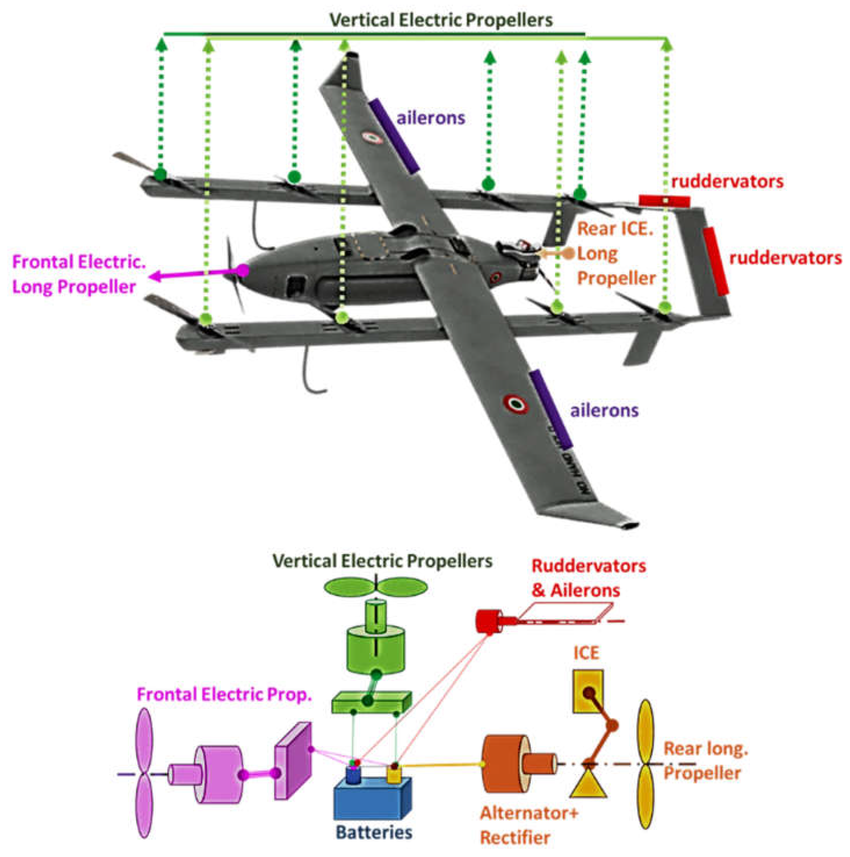
Figure 2a.
Scheme of the complete model of the UAV.
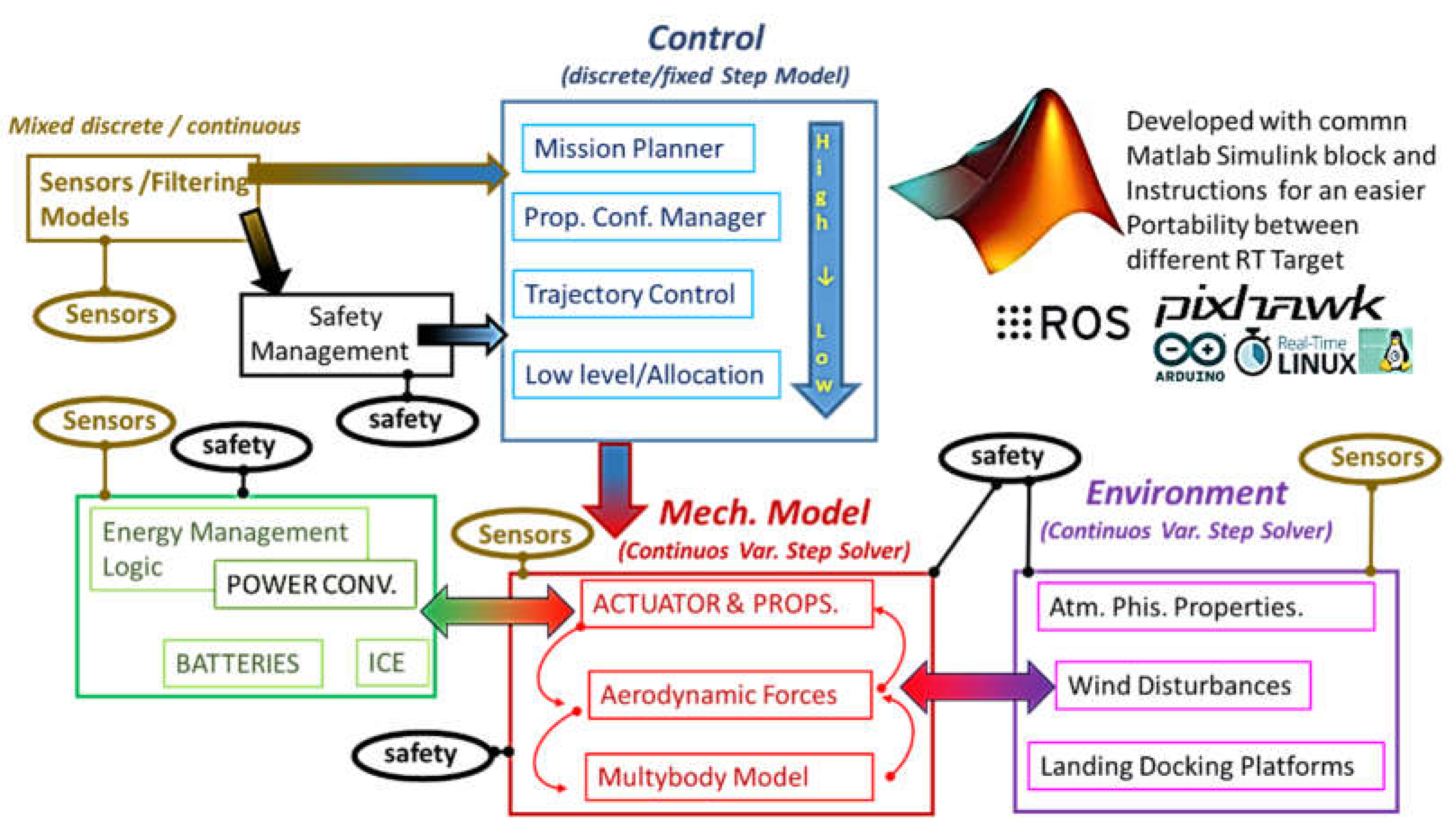
Figure 2b.
Scheme of the testing equipment adopted to verify motor and propeller performances.
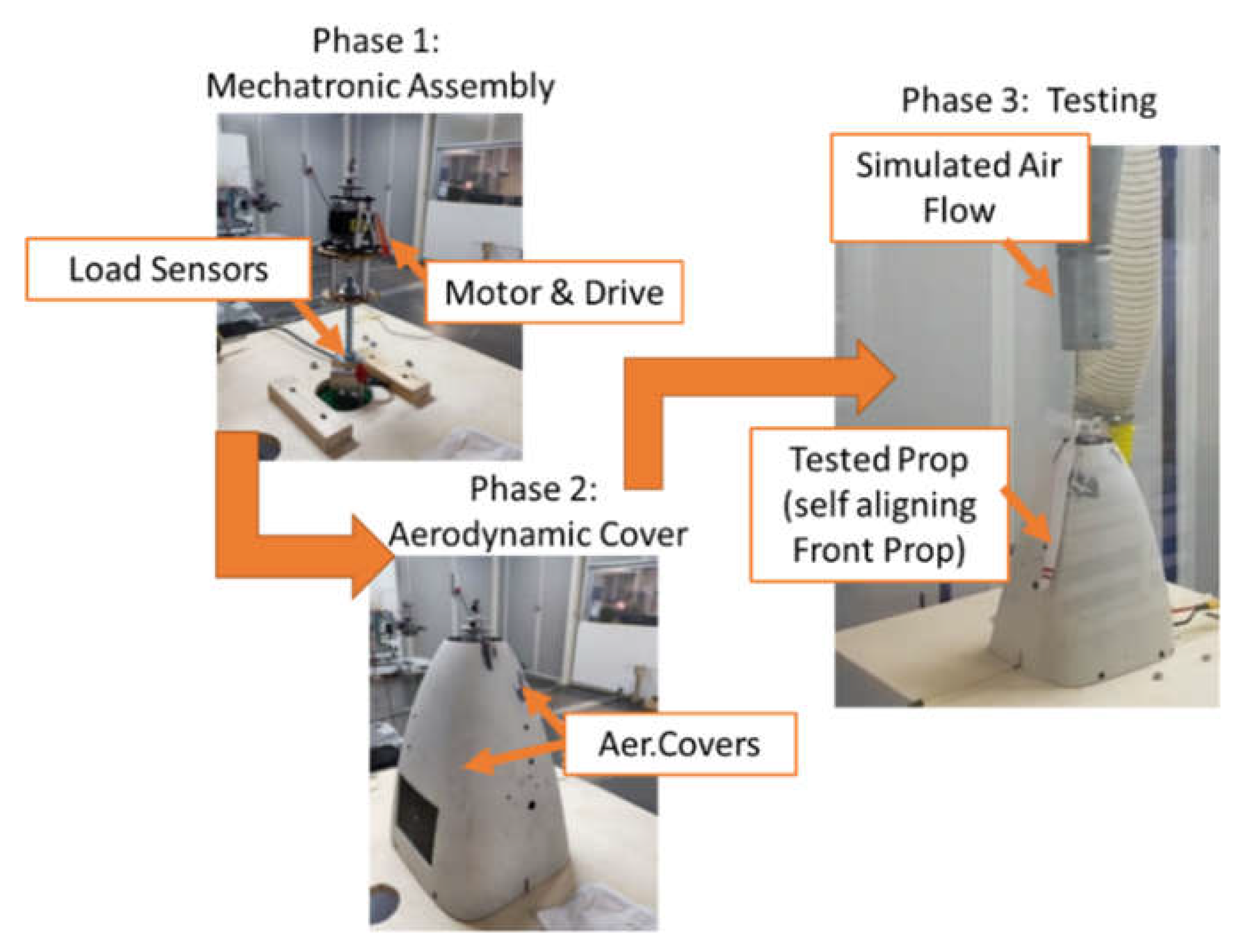
Figure 3.
Sequence of different propulsion and control modes during a mission .
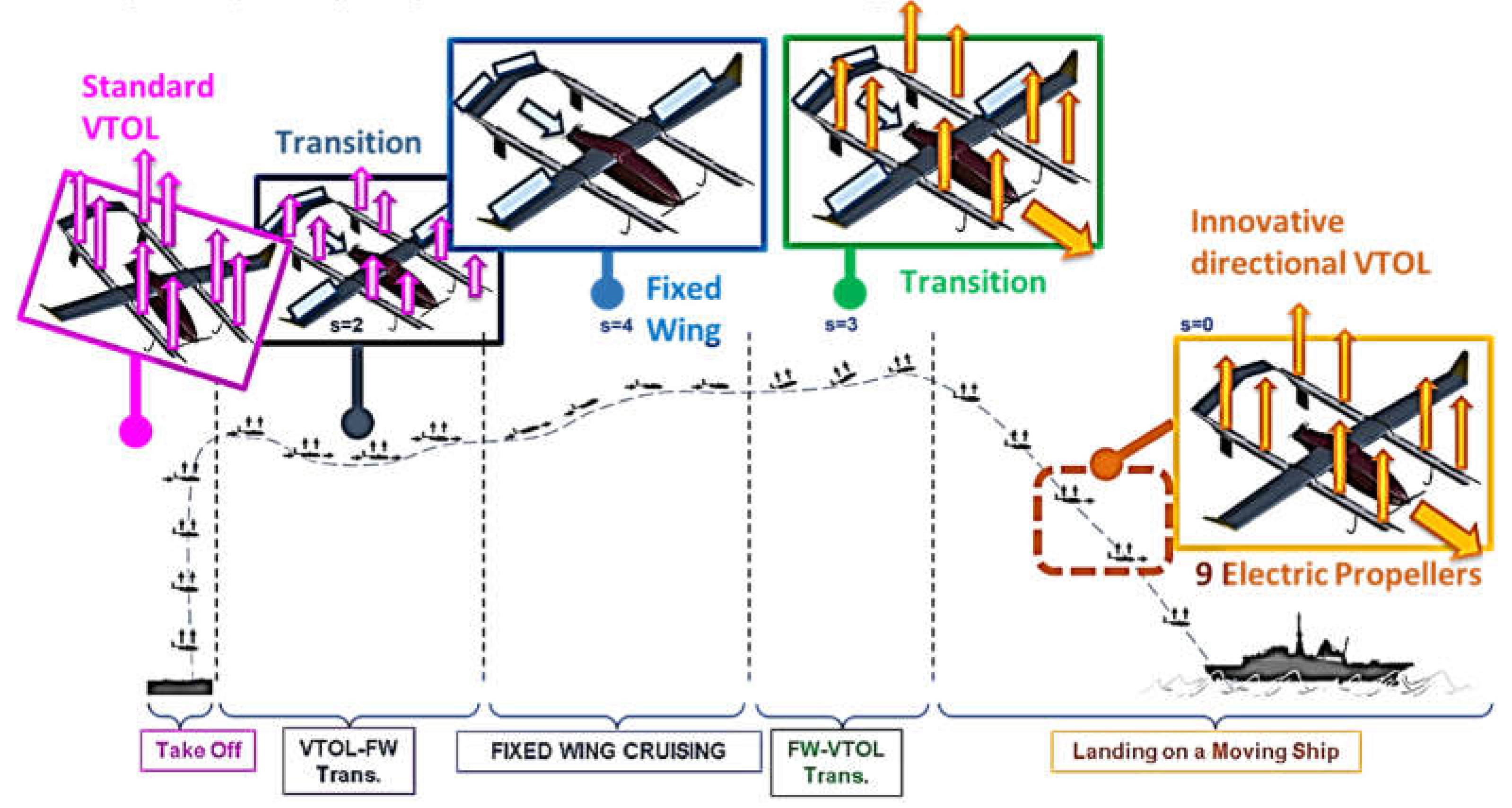
Figure 4.
Definition of heading and course angles.
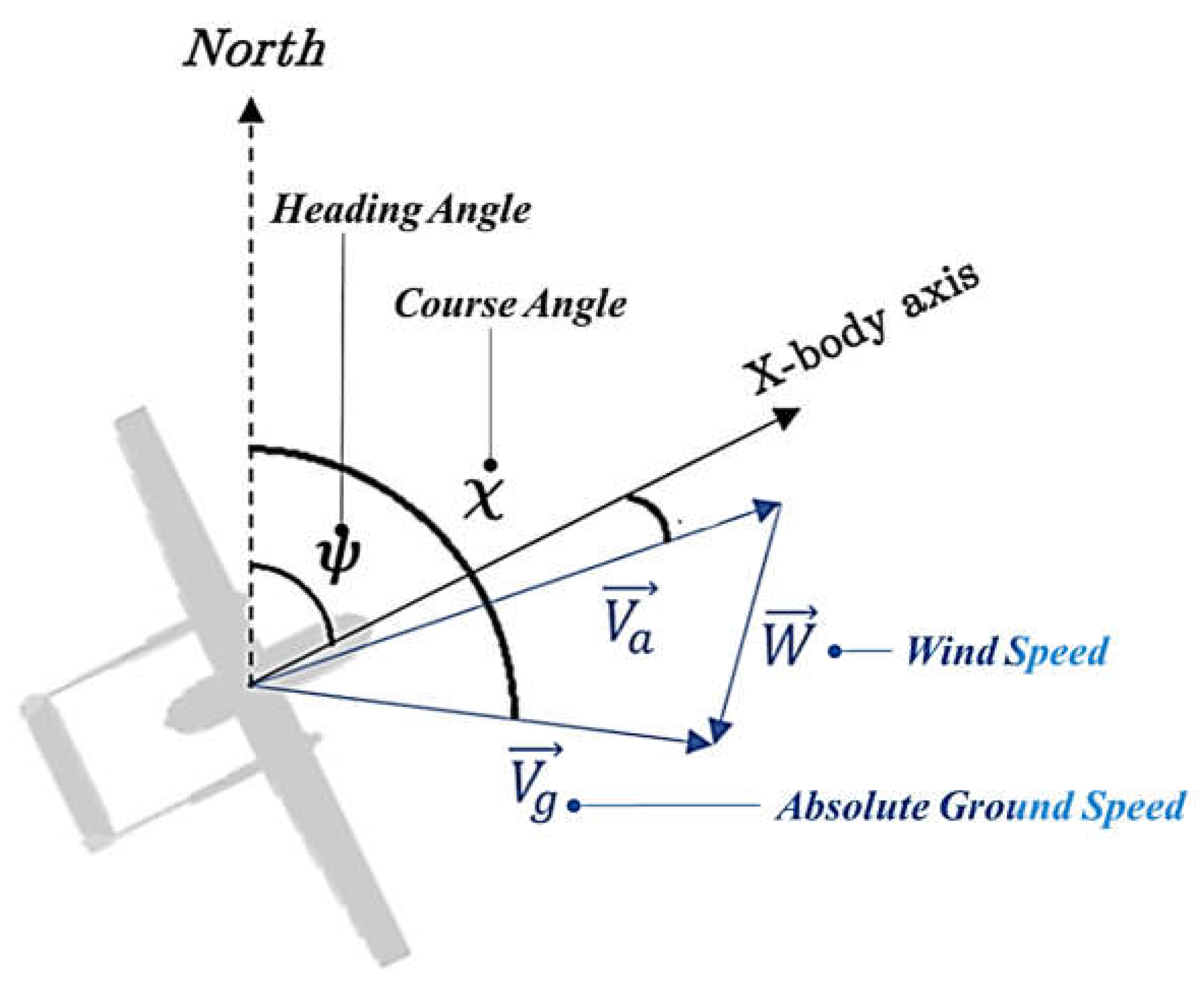
Figure 5.
a/b. Definition of conventional heading control (GH) and the proposed course control (GC).
Figure 5.
a/b. Definition of conventional heading control (GH) and the proposed course control (GC).
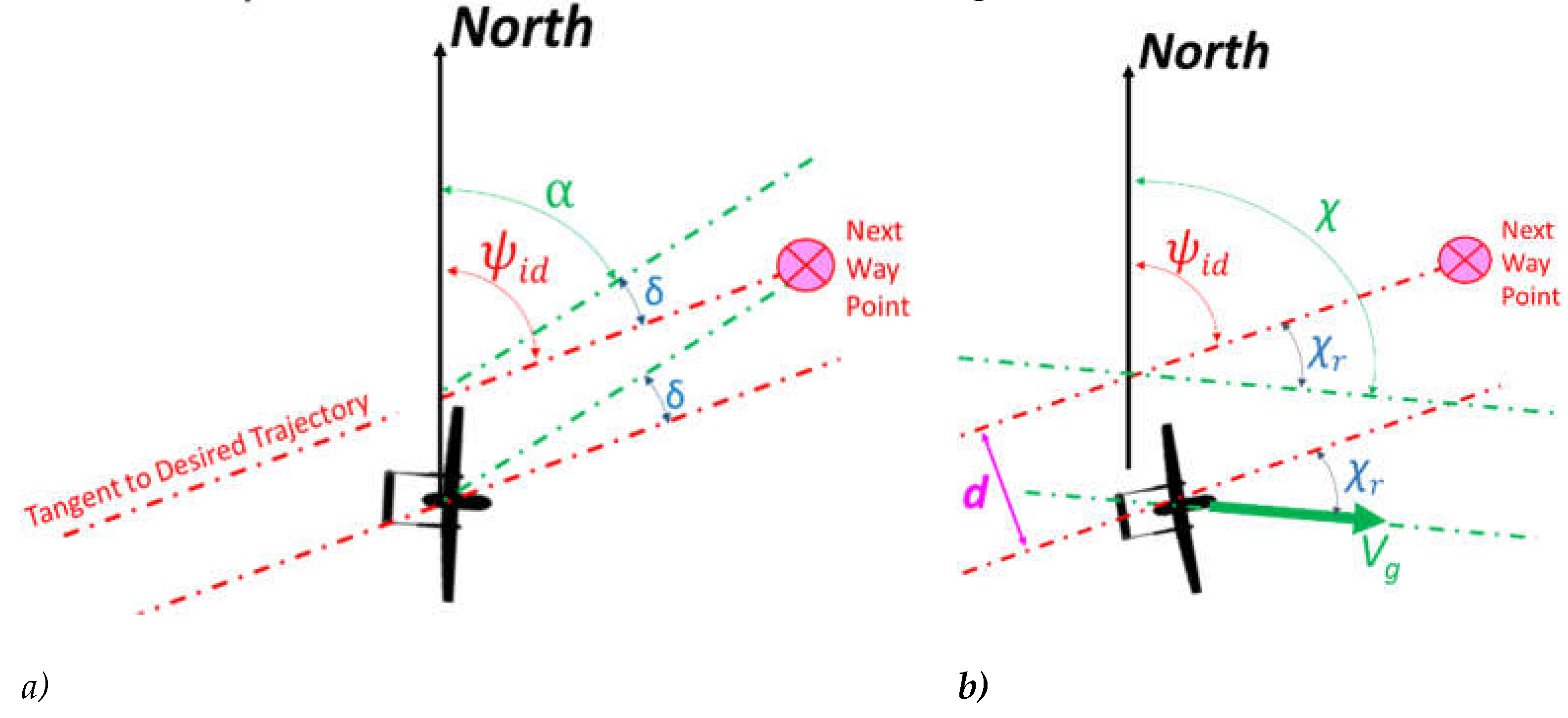
Figure 6.
Inner control loop (a) and simplified model used for the design of SMC(b).
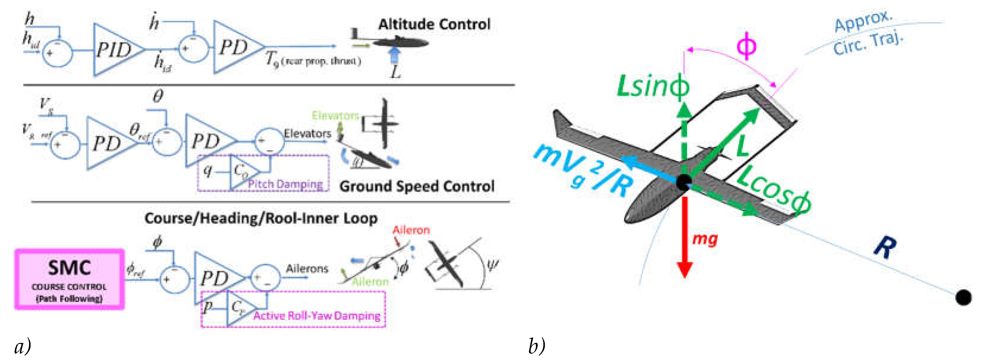
Figure 7.
Applied forces and reaction torques.
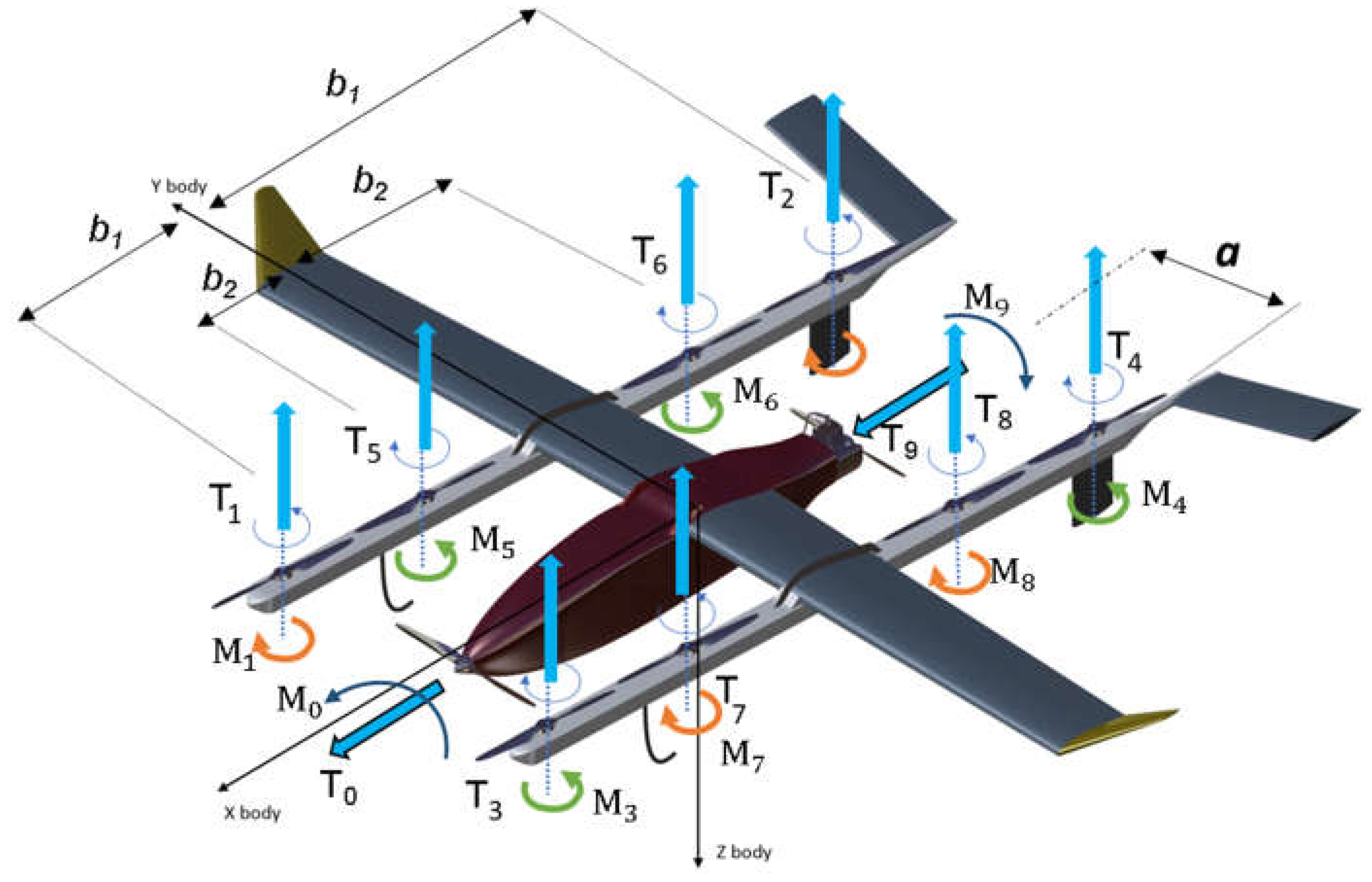
Figure 8.
Proposed directional control (kinematics).
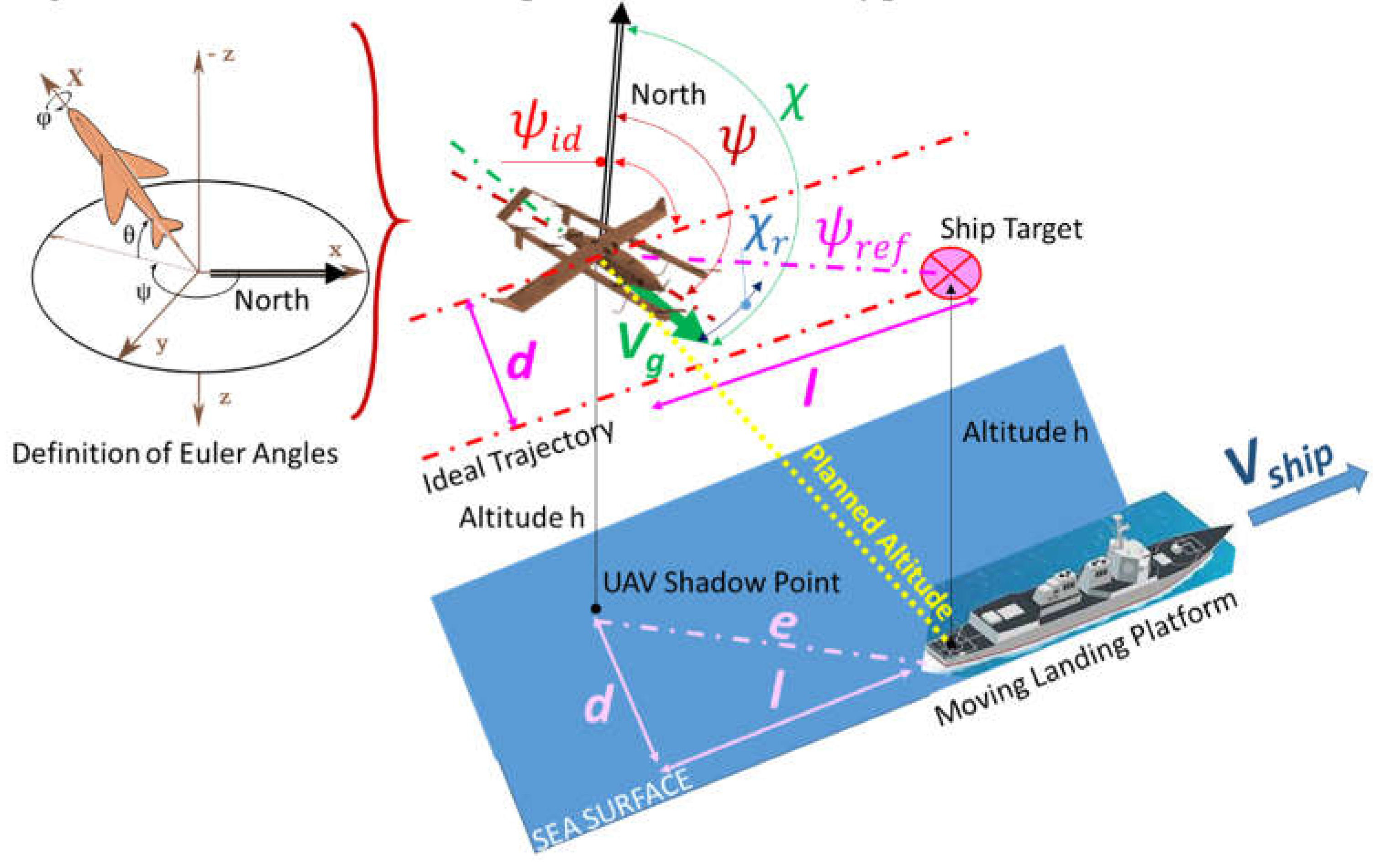
Figure 9.
Simplified structure of the proposed controller.
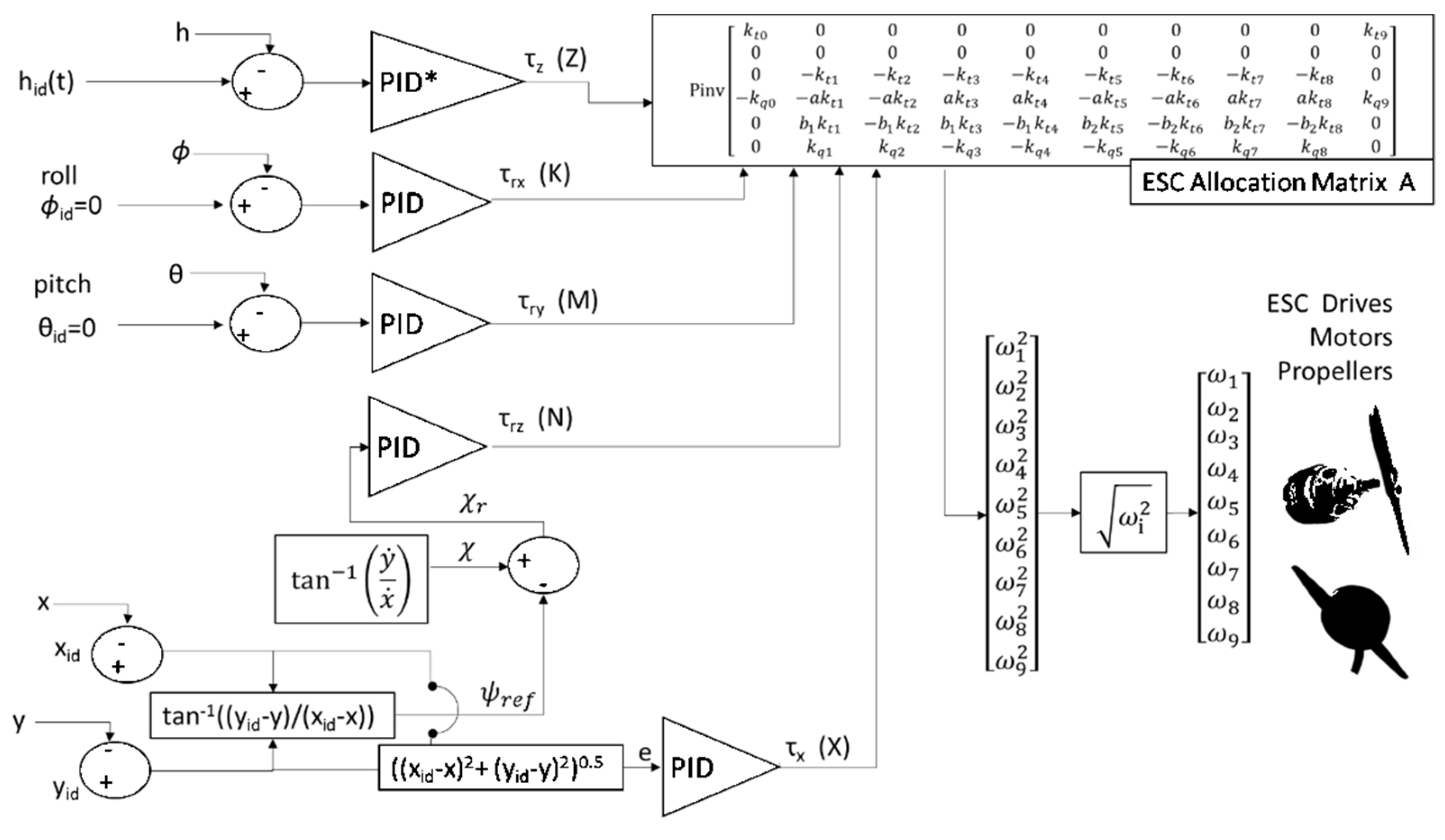
Figure 10a.
Performed Testing (simulation)campaigns.
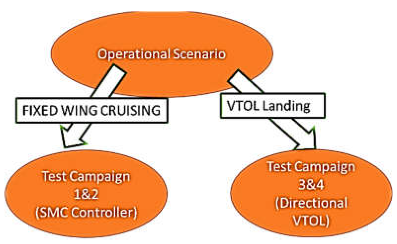
Figure 10b.
Test Campaigns performed to evaluate SMC controller in fixed wing mode.
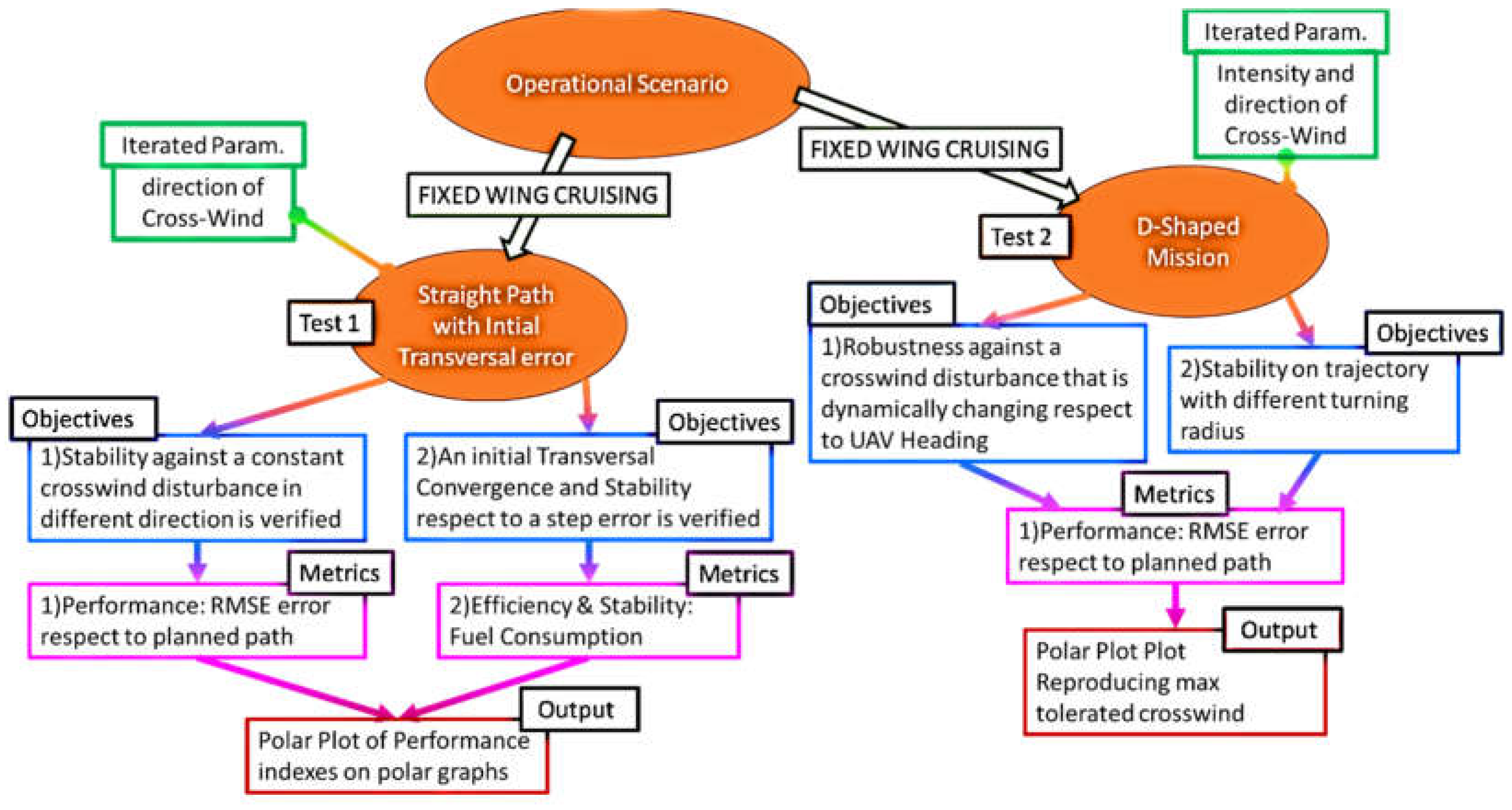
Figure 10c.
Test Campaigns performed to evaluate Directional VTOL during Landing operations.
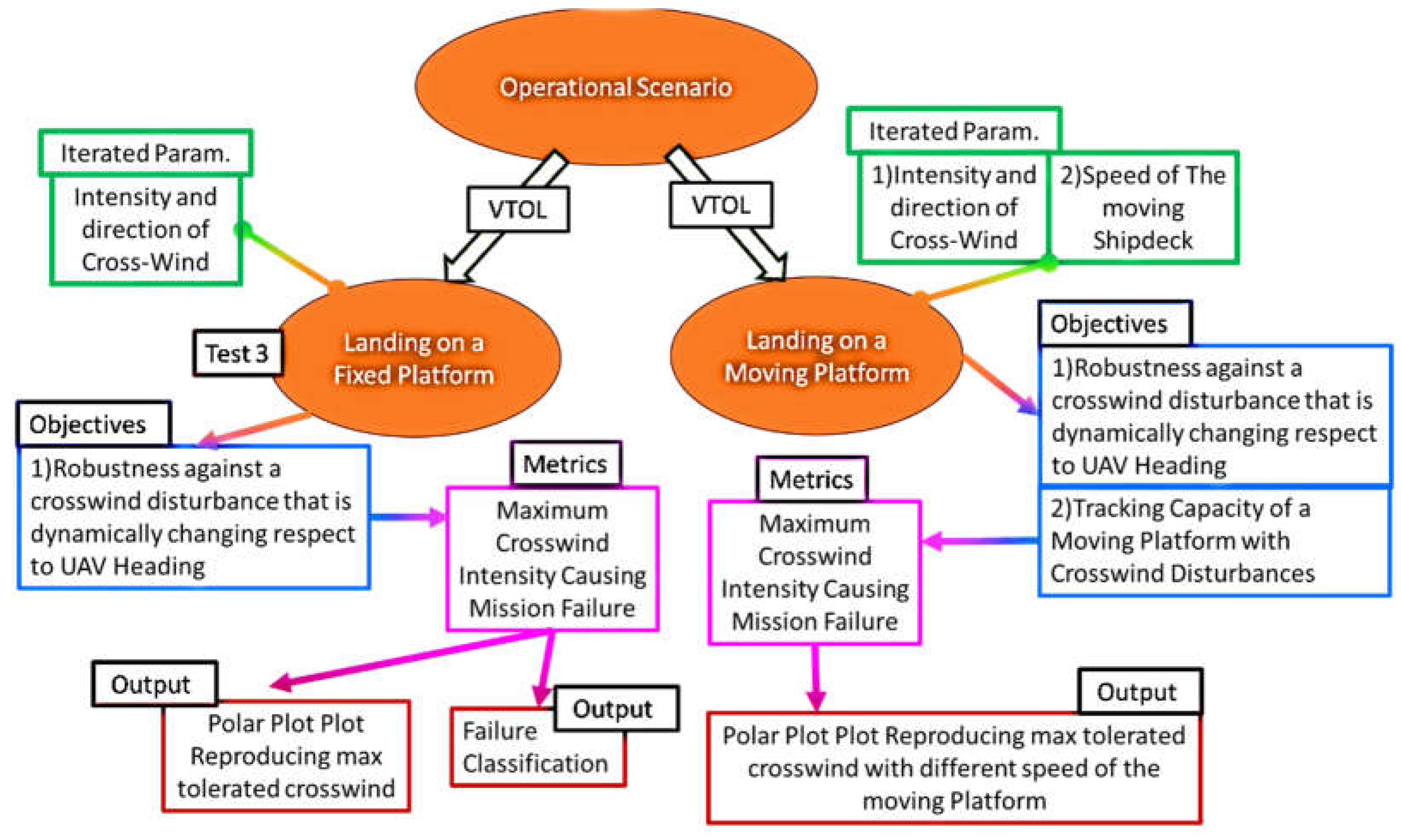
Figure 11a.
Straight mission profile with an initial transversal error.
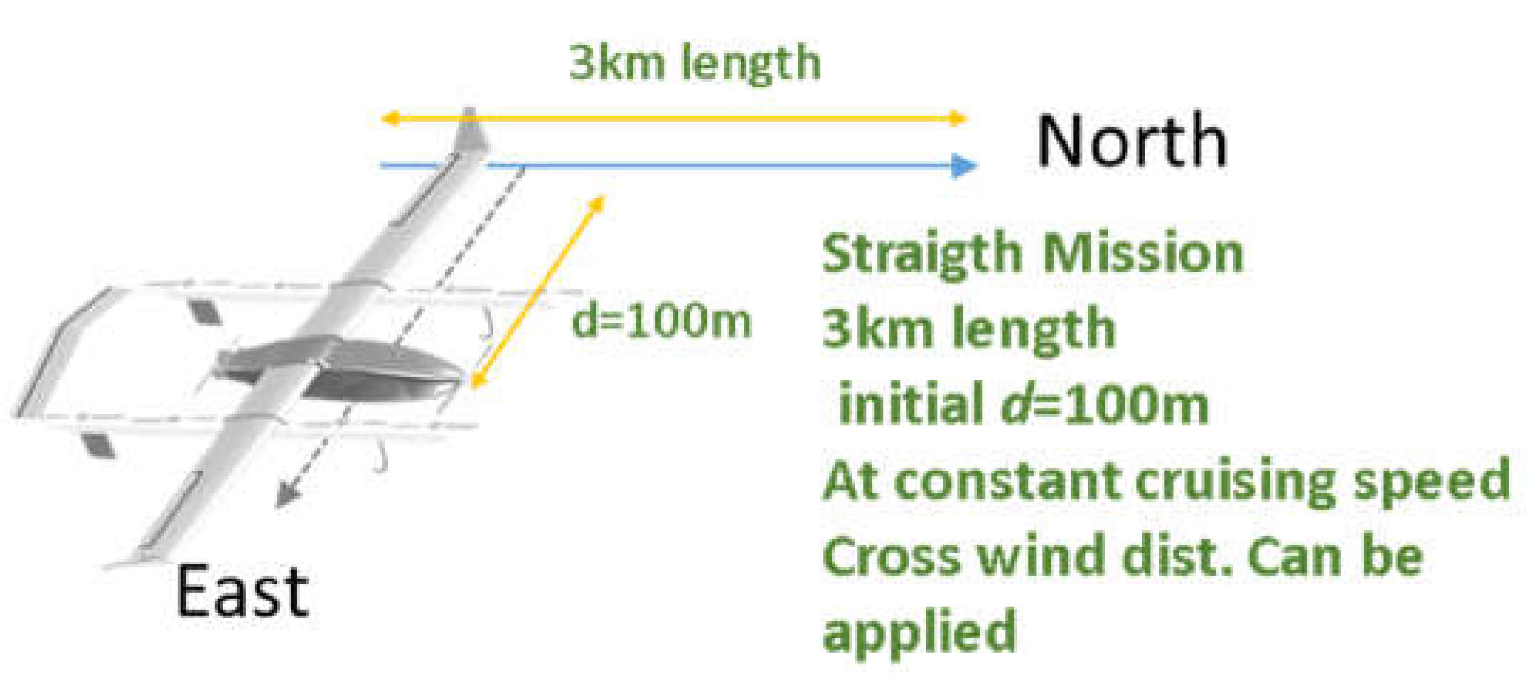
Figure 11b.
Polar Representation of trajectory RMSE of position errors and Fuel consumptions respect to the direction of a wind disturbance with constant amplitude (13m/s).
Figure 11b.
Polar Representation of trajectory RMSE of position errors and Fuel consumptions respect to the direction of a wind disturbance with constant amplitude (13m/s).
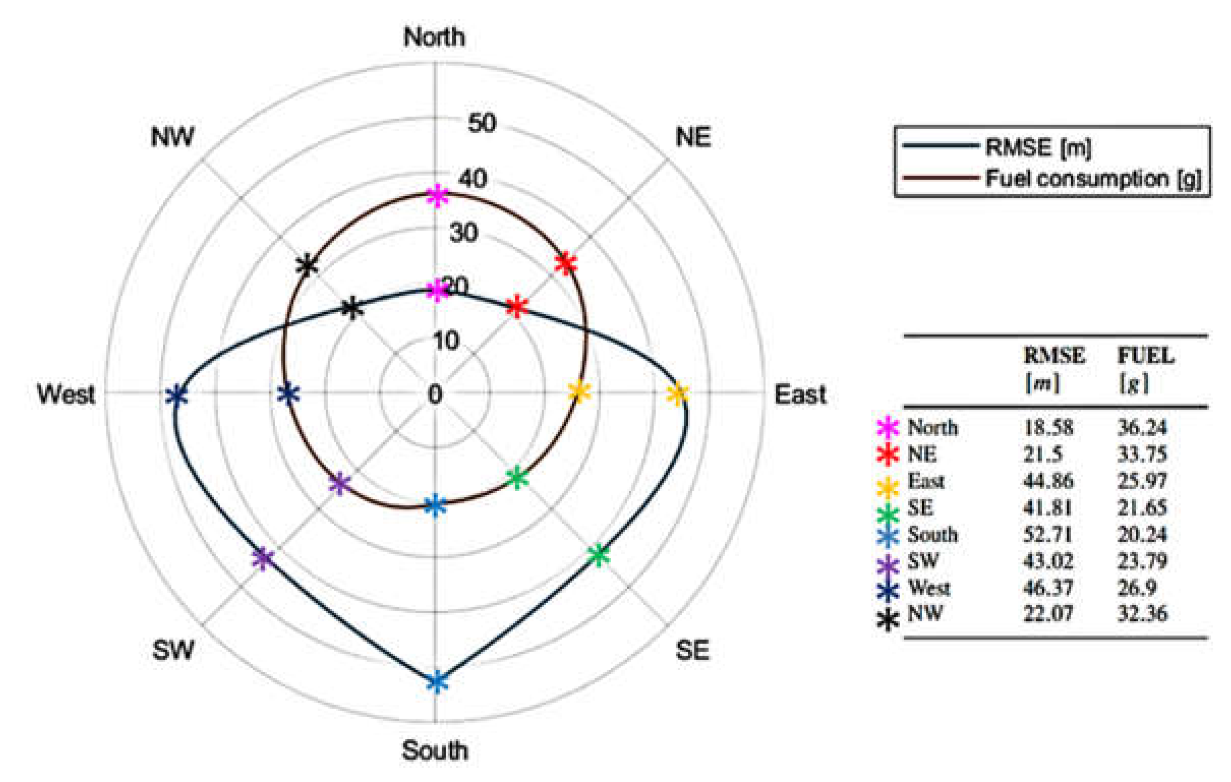
Figure 11c.
Comparison of calculated RMSE as a function of Crosswind direction and intensity for different path controllers.
Figure 11c.
Comparison of calculated RMSE as a function of Crosswind direction and intensity for different path controllers.
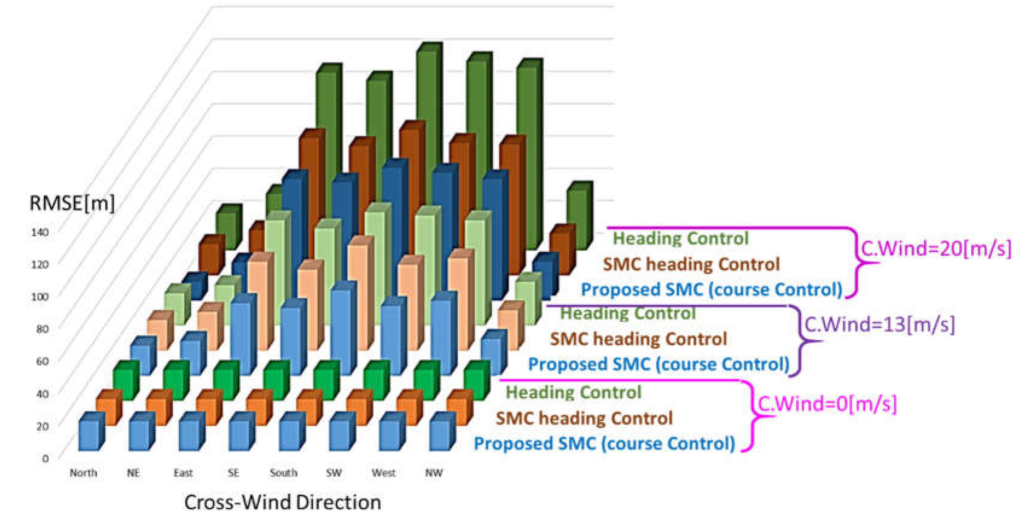
Figure 12.
Polar Representation of trajectory RMSE of position errors and Fuel consumptions respect to the direction of a wind disturbance with constant amplitude and direction (15m/s).
Figure 12.
Polar Representation of trajectory RMSE of position errors and Fuel consumptions respect to the direction of a wind disturbance with constant amplitude and direction (15m/s).

Figure 13.
Comparison ore regulated heading and course angles with different controllers, geometric heading control (left) and SMC Course Control (right).
Figure 13.
Comparison ore regulated heading and course angles with different controllers, geometric heading control (left) and SMC Course Control (right).
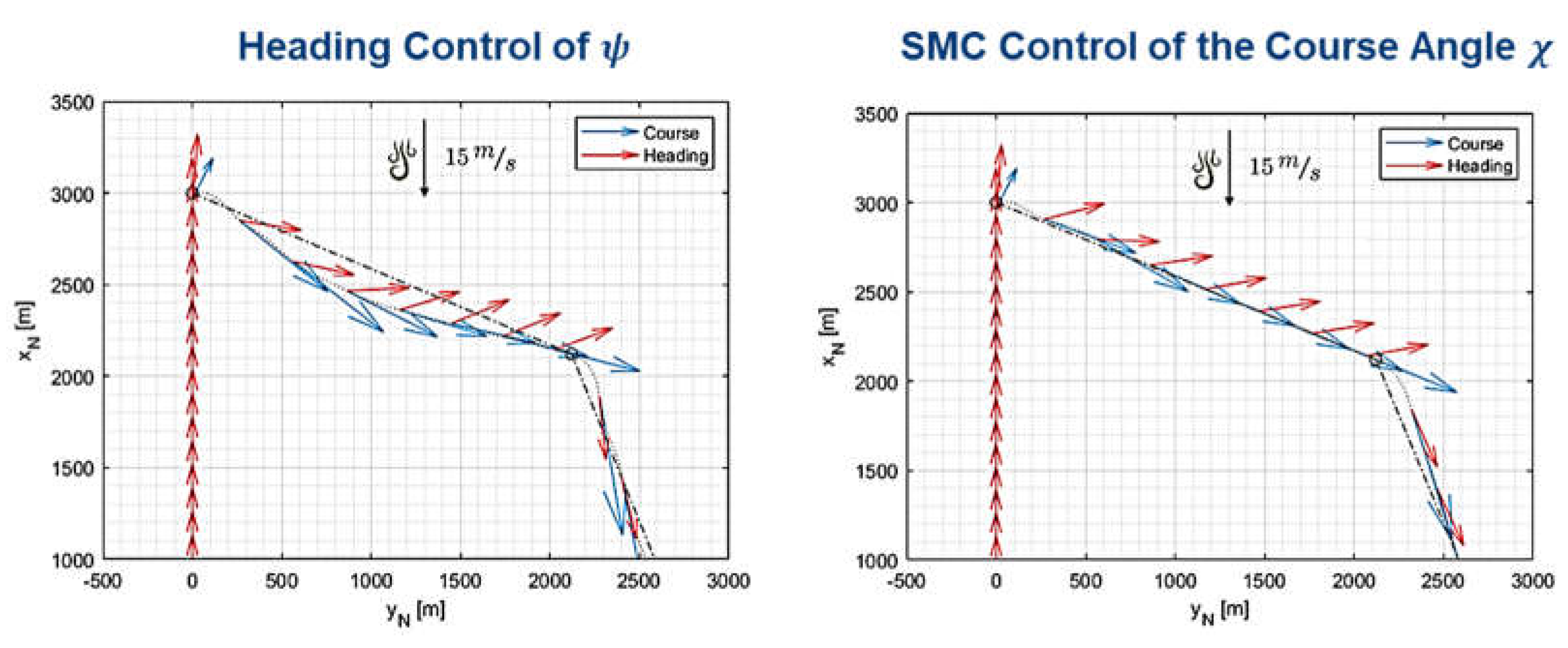
Figure 14.
Polar plot of the maximum wind disturbance that the UAV can reject without failing the D-shaped mission respect to its direction.
Figure 14.
Polar plot of the maximum wind disturbance that the UAV can reject without failing the D-shaped mission respect to its direction.
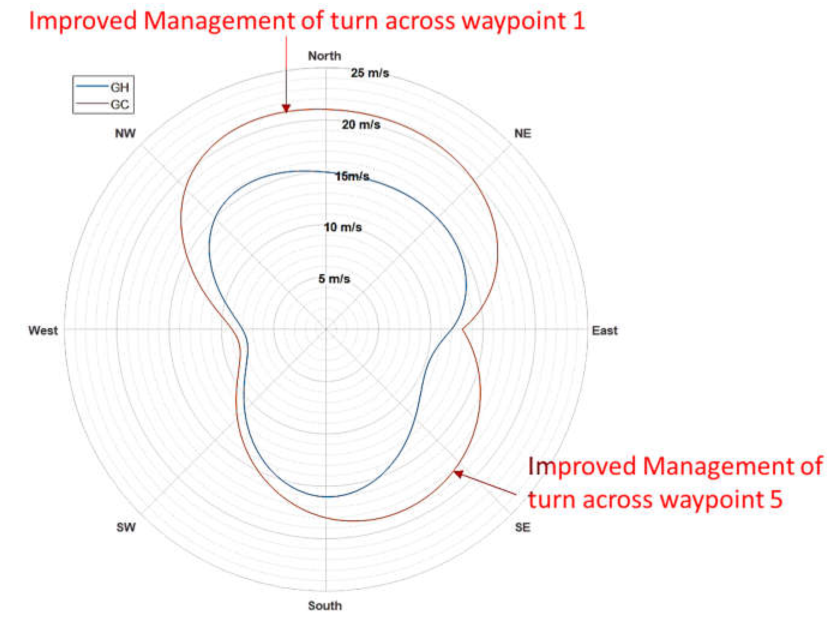
Figure 15.
Landing of on a moving platform.
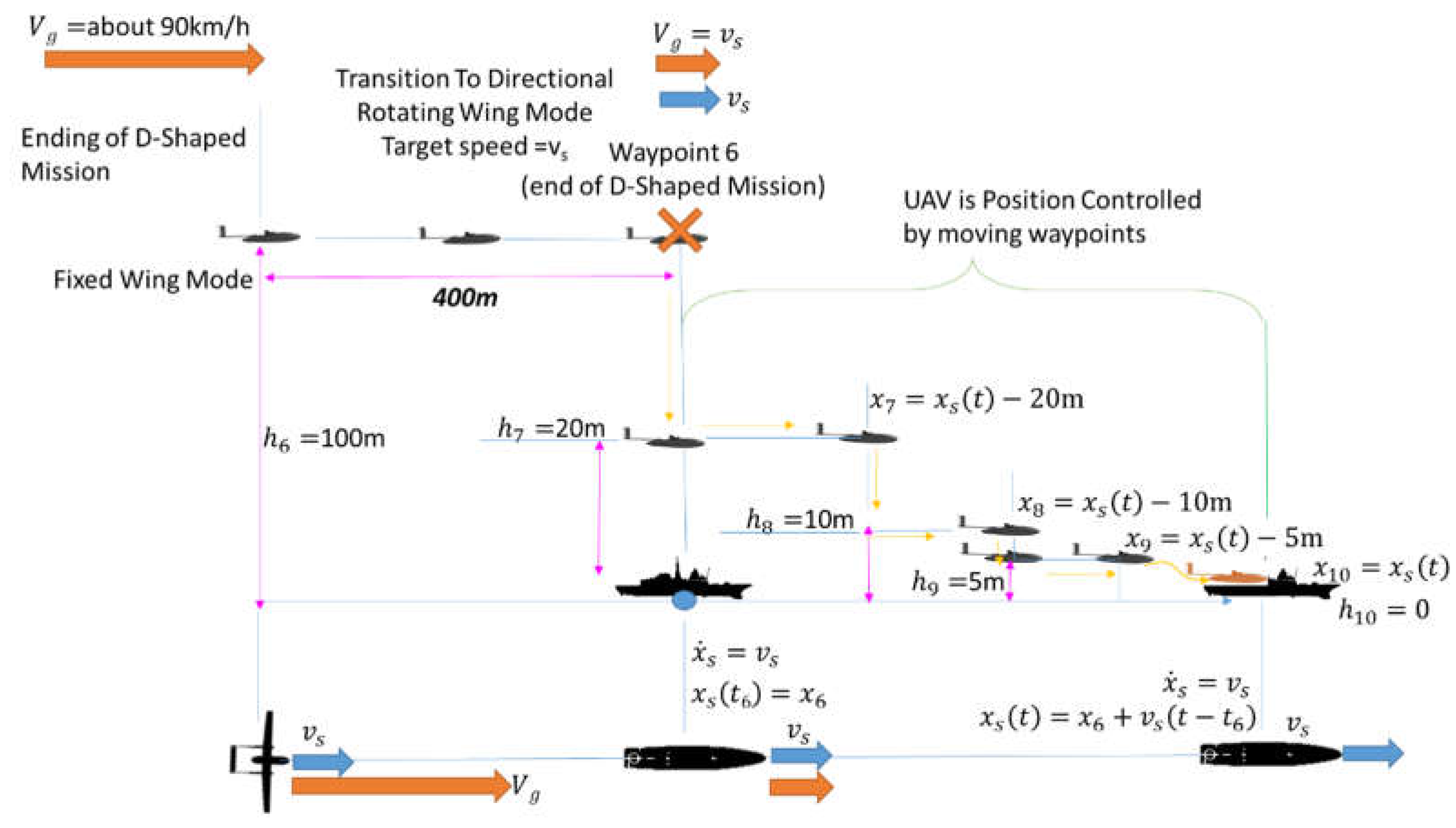
Figure 16.
Landing of on a moving platform with a fixed ship(a) or moving one(b).
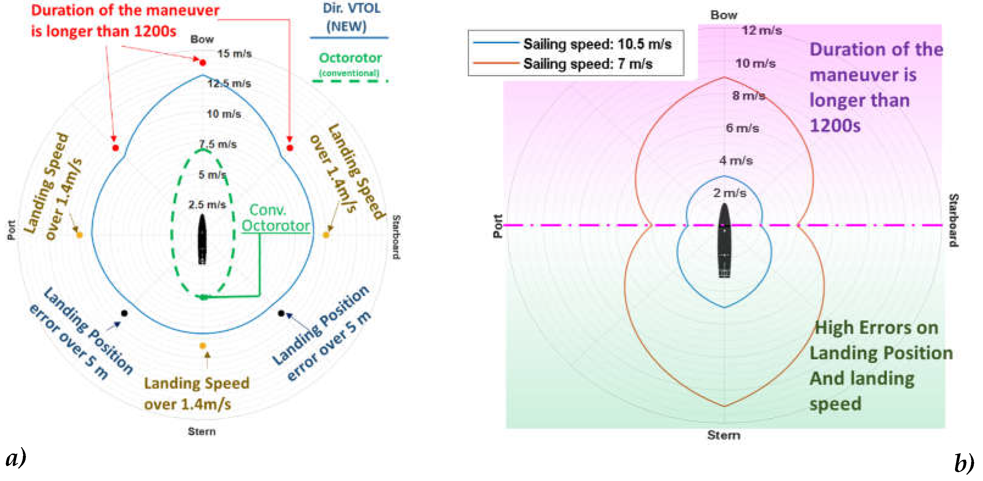
Figure 17.
Maximum Tolerated Crosswind in Hovering (a), time needed by Directional VTOL to reach a stable behavior against crosswind (b).
Figure 17.
Maximum Tolerated Crosswind in Hovering (a), time needed by Directional VTOL to reach a stable behavior against crosswind (b).
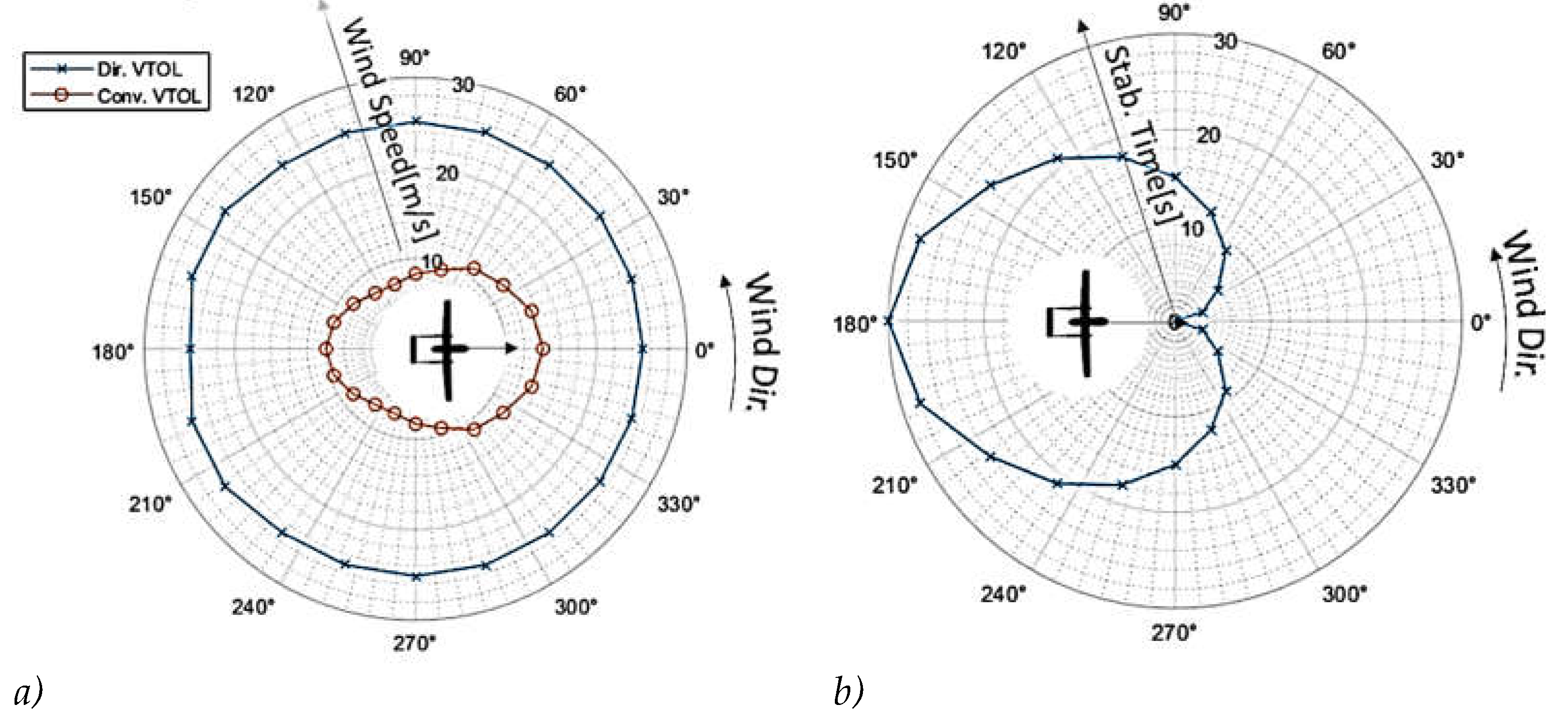
Table 1.
Main features of the investigated UAV[3].
Table 1.
Main features of the investigated UAV[3].
| PARAMETER | VALUE | |
| Wingspan [m] | 3.6 | |
| UAV Weight [kg] | 43.23 | |
| UAV Typ. Operational Speed [m/s] | 24 | |
| Vert.Props. | Max Thrust [kgf] | 13.3 (Max Thrust Tested) |
| Max Power [W] | 3200 (Datasheet) | |
| Installed Storage Size [Ah] | 3.25 (x8) | |
| ICE Long. Prop. | Max Thrust [kgf] | 6 (only ICE)/ 12.5(ICE+electrical boost) |
| Max Power [W] | 1515 (only ICE) | |
| ICE Power [W] | 1500@7000rpm (1800@9000rpm) | |
| ICE Motor | 2 Stroke Engine 29cc | |
| Elect.Long. Prop. | Max Thrust [kgf] | 12.2 (Max Thrust Tested) |
| Max Power [W] | 3744 (Datasheet) | |
| Installed Storage Size [Ah] | 23 | |
Table 2.
Comparison of expected performances of propellers from datasheet and corresponding values recorded during experimental tests (referred to null advance speed tests).
Table 2.
Comparison of expected performances of propellers from datasheet and corresponding values recorded during experimental tests (referred to null advance speed tests).
| Prop .Speed (vertical prop.) | Thrust (expected) | Thrust meas. on ground (200m alt.) |
| 2400[rpm] | 1.35[kgf] | 1.66(1.62) [kgf] |
| 4000[rpm] | 3.84[kgf] | 4.31(4.21) [kgf] |
| 5000[rpm] | 6.12[kgf] | 7.20(7.03) [kgf] |
| 5800[rpm] | 8.33[kgf] | 9.8(9.58) [kgf] |
| 6300[rpm] | 9.9[kgf] | 11.37(11.1) [kgf] |
| 6700[rpm] | 11.25[kgf] | 13.3(13)[kgf] |
| Prop .Speed (long prop.) | Thrust (expected) | Thrust meas. on ground (200m alt.) |
| 2450[rpm] | 1.26[kgf] | 1.71(1.67) [kgf] |
| 3900[rpm] | 3.67[kgf] | 4.56(4.45) [kgf] |
| 5000[rpm] | 6.36[kgf] | 7.26(7.09) [kgf] |
| 5650[rpm] | 8.32[kgf] | 9.72(9.49) [kgf] |
| 6100[rpm] | 9.85[kgf] | 11.22(10.95) [kgf] |
Disclaimer/Publisher’s Note: The statements, opinions and data contained in all publications are solely those of the individual author(s) and contributor(s) and not of MDPI and/or the editor(s). MDPI and/or the editor(s) disclaim responsibility for any injury to people or property resulting from any ideas, methods, instructions or products referred to in the content. |
© 2023 by the authors. Licensee MDPI, Basel, Switzerland. This article is an open access article distributed under the terms and conditions of the Creative Commons Attribution (CC BY) license (http://creativecommons.org/licenses/by/4.0/).
Copyright: This open access article is published under a Creative Commons CC BY 4.0 license, which permit the free download, distribution, and reuse, provided that the author and preprint are cited in any reuse.


