

Submitted:
24 October 2026
Posted:
26 October 2026
You are already at the latest version
Abstract
To address image degradation caused by dust/fog scattering and non-uniform illumination in mine surveillance footage, this paper proposes an improved dark channel prior method based on the HSV brightness component. The method constructs a dark channel using the V component of the HSV color space via morphological erosion, estimates atmospheric light through random sampling and lower-bound constraints, and refines and fuses the transmission map using multi-scale guided filtering; Gamma correction is applied after recovering the V component to enhance brightness in dark areas. Experimental images were obtained from the Gaojialiang Coal Mine; scenes with varying degrees of degradation were selected for comparative evaluation, and multiple YOLO models were used to assess the impact of the enhancement process on personnel detection. Averaged across six representative mine scenes, the proposed method achieved a mean gradient of 8.606, a mean edge density of 14.072%, and a mean NIQE of 3.279. Compared to the original images, edge density increased from 10.551% to 14.072%, and the NIQE score dropped from 4.175 to 3.279. Personnel detection case studies demonstrated that the enhancement process improved detection results in dusty and foggy scenes. The results indicate that the proposed method enhances the visibility of object contours and local details in the tested mine scenes, achieves favorable no-reference image quality assessment scores, and reduces computational complexity, thereby offering a valuable reference for image processing in mine visual surveillance.
Keywords:
underground mine images
; dust haze
; non-uniform illumination
; HSV value component
; trans-mission estimation
; image enhancement
1. Introduction
Vision-based tasks such as personnel detection and anomaly monitoring rely on high-quality underground surveillance images. However, dust scattering reduces image contrast and blurs object boundaries, while uneven artificial illumination causes underexposure, local highlights, and halo artifacts. As a result, underground mine images are often affected by coupled dust-haze and illumination degradation rather than a single distortion. This composite degradation poses a major challenge to reliable image enhancement and subsequent visual analysis.
Figure 1.
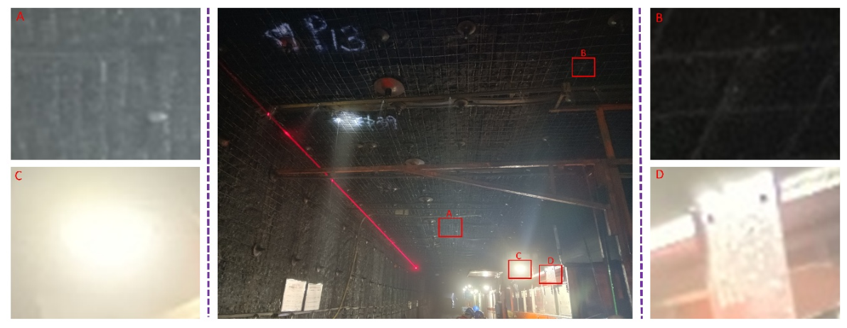
Real-world image captured by an underground industrial camera in a coal mine roadway (4080×3060). Magnified regions show four typical degradations: dust-induced light scattering causing contrast loss and blurred contours (A); low illumination leading to texture loss (B); high-intensity point lights producing halos via dust scattering (C); and overexposure from direct light and surface reflection (D).
Figure 1.
Real-world image captured by an underground industrial camera in a coal mine roadway (4080×3060). Magnified regions show four typical degradations: dust-induced light scattering causing contrast loss and blurred contours (A); low illumination leading to texture loss (B); high-intensity point lights producing halos via dust scattering (C); and overexposure from direct light and surface reflection (D).
Existing deep learning-based image enhancement and restoration methods primarily employ three training paradigms—paired supervised, unsupervised, and self-supervised learning—based on the nature of the supervisory signals [1,2,3,4]. Regarding model architecture, Transformers and diffusion models have been introduced to image restoration to improve the modeling of long-range dependencies and the representation of complex degradation features [5,6,7,8,9]. While paired supervised learning relies on strict pairings of clear and degraded images, unsupervised and self-supervised approaches relax these pairing requirements but still necessitate specific degraded samples and reliable priors. In underground coal mines, conditions such as dust and non-uniform illumination make it impossible to acquire clear, paired images. Furthermore, significant variations in lighting layouts and dust concentrations across different mine sites lead to a shift between the training and target domains; this degrades model performance and limits generalization capabilities, making it difficult to directly meet the demands of image processing in complex, real-world mining environments.
Apart from deep learning-based approaches, existing methods primarily fall into two categories: traditional enhancement techniques and physics-prior-based methods [10,11,12,13,14,15,16,17,18,19,20,21]. Traditional enhancement methods often result in color shifts and localized over-enhancement, making them ill-suited for dusty and foggy underground conditions [10,11,12,13,14,15,16]. While physics-prior-based methods possess clear physical significance, they are largely designed for outdoor imagery and are difficult to apply directly to mining environments; furthermore, their performance relies heavily on the accurate estimation of physical parameters [17,18,19,20,21]. To address this issue, to the best of our knowledge, no public benchmark dataset is currently available for images acquired in complex underground environments. We therefore constructed a dataset consisting of real-world underground images collected from the Gaojialiang Coal Mine and mine safety monitoring systems. This dataset includes industrial camera images (4080 × 3060 resolution) and working-face surveillance footage (1920 × 1080 resolution), capturing typical degradation scenarios caused by dust, haze, and complex lighting conditions. Based on an analysis of these images, we propose an HSV-DCP-based enhancement method for mine imagery; our primary contributions are as follows:
- To tackle the problem of coupled multiple degradation factors in complex mine environments, the applicability of different enhancement methods is analyzed, and key parameters are identified via parameter sensitivity experiments. This provides a basis for the engineering optimization of the algorithm in real mine scenarios.
- A dark channel is constructed based on the value component in the HSV color space. A random atmospheric light sampling strategy and multi scale guided filtering are introduced to perform joint optimization of the transmittance map, followed by gamma correction. This design improves the algorithm’s adaptability to scenes with non uniform dust fog and complex illumination conditions.
- Extensive image quality assessment across various complex mine scenarios and validation with multiple object detection models on the enhanced results demonstrate that the proposed method can improve the detection performance of mine personnel targets while boosting the visual quality of mine images.
2. Related Work
2.1. Traditional and Physical Prior-Based Methods
They are characterized by simple implementation and relatively high computational efficiency, and can effectively enhance local contrast [10,11,12,13,14,15,16]. However, in low-illumination regions, they tend to simultaneously amplify noise and cause local over-enhancement. Retinex theory [13] recovers information in dark regions by separating illumination and reflectance components. Typical methods include single-scale Retinex (SSR) [14], multi-scale Retinex (MSR) [15], and MSR with color restoration (MSRCR) [16]. These approaches have been applied to the enhancement of mine and low-light scenes. However, their performance is highly sensitive to scale and gain parameters, and they tend to produce halos and color shifts in non-uniform high-intensity illumination areas. Homomorphic filtering enhances the visibility of local structures by separating illumination and reflectance components in the frequency domain. However, it struggles to characterize the scattering process induced by dust haze. Physics-based dehazing methods typically rely on the atmospheric scattering model [17], with representative approaches including the Dark Channel Prior (DCP) and the Color Attenuation Prior (CAP) [18,19,20,21]. These methods estimate transmittance or scene depth based on the color distribution and statistical characteristics of images to achieve dehazing. While they do not require large-scale training data and offer broader applicability, their underlying priors are generally formulated based on natural lighting and the statistical properties of outdoor images; consequently, under conditions of localized non-uniform illumination and coal dust scattering in mines, they can lead to parameter estimation errors—resulting in color shifts and significant image darkening—which compromise the quality of the restored image.
2.2. Deep Learning-Based Image Enhancement Methods
Compared to fixed image priors, deep learning enables the learning of texture features and non-linear recovery relationships from training samples, offering a data-driven approach to addressing complex image degradation [22,23,24]. While DehazeNet [25] and MSCNN [27] recover scene radiance via transmission estimation, errors in intermediate parameter estimation propagate to the final results; AOD-Net [26] mitigates error accumulation from staged estimation by reparameterizing and jointly estimating components of the atmospheric scattering model, yet it remains constrained by the underlying physical model. CycleDehaze [28] employs unpaired learning to relax data registration requirements but still relies on datasets of hazy and clear images. Light-DehazeNet [29] focuses on reducing computational costs, and generative adversarial dehazing methods [30] prioritize matching image distributions; however, their training stability depends on high-quality datasets, making them unsuitable for mine environments.
Transformer-based methods have transformed feature interaction patterns. Restormer [3] utilizes an efficient attention mechanism for high-resolution image restoration; Retinexformer [5] introduces illumination guidance to enhance feature modeling in low-light regions; and DehazeFormer [7] adapts normalization and spatial information aggregation mechanisms specifically for dehazing tasks. Although these methods improve illumination modeling and dehazing architectures, they generally target single degradation scenarios and fail to address the multi-degradation conditions found in mines. PromptIR [8] enables unified processing for dehazing, deraining, and denoising via degradation prompts, but using a single model for diverse tasks prevents the simultaneous recovery of multiple degradation types in mine images. FoundIR [9] leverages a large-scale dataset of real paired images and a diffusion-based restoration framework; however, the stochastic nature of iterative diffusion sampling risks compromising the structural fidelity and physical consistency of mine images.
Most existing methods are designed for specific types of outdoor image degradation; consequently, they struggle to simultaneously achieve dust/haze removal, non-uniform illumination correction, and local glare suppression within the complex, multi-factor environment of a mine. In contrast, unified restoration methods addressing multiple types of degradation typically treat issues such as haze, rain, and noise as distinct tasks, employing prompt learning or task-specific branches to facilitate task switching. However, in mine imagery, various forms of degradation often spatially overlap and coexist—with a single region simultaneously affected by factors like dust scattering, low illumination, local overexposure, and noise—making it difficult for existing methods to effectively characterize these coupled degradation relationships.
2.3. Mine Image Enhancement Methods
In recent years, research on mine image enhancement has progressively evolved from single-task low-light correction and dehazing toward joint restoration of multiple degradations. Early methods improved illumination in underground mines through illumination–reflectance decomposition and multi-scale guided filtering [31,32]. These approaches entail relatively low data dependency but are primarily focused on adjusting illumination distribution, with insufficient handling of dust haze. Subsequently, deep learning-based networks have achieved stepwise decoupling of illumination adjustment and noise removal at the feature level, and this core idea has been widely adopted in mine vision-related studies [33]. More recently, the research focus has shifted from single-task enhancement to joint low-light and dehazing processing, aiming to simultaneously address insufficient illumination and haze-induced blurring in underground images [34,35,36,37]. These efforts indicate that joint restoration can better adapt to complex underground degradations than single-task models.
To further evaluate the applicability of existing methods in real mining environments, we select four traditional enhancement methods (Retinex [13], MSRCR [16], CAP [19], and DCP [18]) and four representative state-of-the-art approaches (AOD-Net [26], MixDehazeNet [22], DehazeSNN [21], and HistoFusionNet [24] for comparative experiments on two typical real-world mine scenes, as shown in Figure 2. From a subjective perspective, current image enhancement methods still struggle to effectively accommodate the composite degradation scenarios encountered in real mine images; thus, it is necessary to progressively pursue research on composite degradation enhancement models.
3. Theoretical Model
3.1. Atmospheric Scattering Model Theory
Dark channel prior [18] is an important theory in the field of image defog, the basis of which can be traced back to the atmospheric scattering theory proposed by McCartney [17] The atmospheric scattering model is used to describe the process of light propagation in media such as dust and haze, and its core idea is the interaction between electromagnetic waves and atmospheric particles. The model can be expressed as follows:
where I(x) denotes a foggy image; J(x)t(x) is the direct attenuation term, which represents the light intensity of the fogless image J(x) attenuated by the transmittance t(x), where t(x) = e−βd(x)has a negative exponential relationship with the scene depth d (x), reflecting the proportion of light that is not scattered, β is the atmospheric scattering coefficient, which is determined by the characteristics of particles, and Rayleigh scattering and Mie scattering correspond to different β calculations; A(1 − t(x)) is an atmospheric light superposition term, which means that atmospheric light A is superimposed on the observation image due to scattering. Atmospheric light A usually takes the maximum RGB value of the brightest area in the natural image, representing the global light intensity.
I(x) = J(x)t(x) + A(1 − t(x))
3.2. A Priori Theory of Dark Channels
According to the prior theory of dark channels, in the non-sky region of natural fog-free images, there is at least one color channel whose minimum value is close to zero in the local window. The specific expression is shown in Formula (2):
In the formula: Ω(x) (window size of 15*15) [18] represents the local window centered on pixel x, and Jc represents the pixel values of the clear image in the three color channels of R, G, and B. The formula takes the minimum value of the three RGB channels of each pixel in the window, and then takes the minimum value in the window range, so as to realize the minimum value filtering of the dark channel.
Equation (3) is obtained by dividing the atmospheric light value A on both sides of Equation (1) at the same time, and performing two minimum value operations:
In the formula: the atmospheric light value calculation expression , that is, the maximum value extracted from the corresponding position of I(x) for the top 0.1% pixels of brightness in the dark channel map. Knowing A, the transmittance can be estimated:
In order to retain a certain amount of fog and enhance the depth of the scene, the adjustment factor ω(ω∈(0,1), ω=0.95)[18] is introduced. The solution formula for the transmittance is:
The fog-free image J(x) can be deduced inversely by finding) and A. Experiments show that when t(x) is too small, J(x) will be too large. Therefore, a threshold of t0(t0 = 0.1 ) [18] is introduced to limit the calculation deviation caused by a specific scene, so that when t(x) is not lower than this value. The final fog-free image J(x) is calculated by:
Owing to the use of filtering windows, the transmittance map corresponding to the dark channel exhibits block effects. The Soft Matting method is applied to refine . Although it achieves excellent performance, this approach has high computational complexity and is not applicable to practical scenarios. Subsequently, He proposed an optimization strategy based on Guided Filtering, which effectively improves computational efficiency.
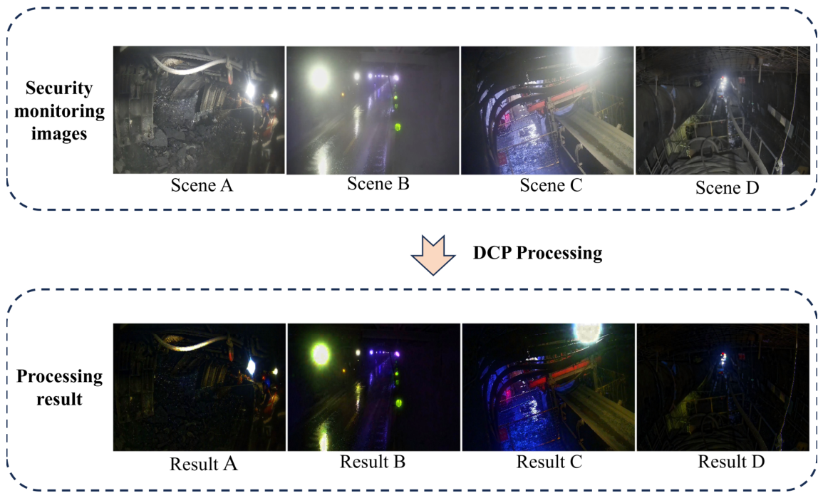
The practical performance of DCP was evaluated on a real-world security monitoring image dataset. As illustrated in the figure, the DCP-processed images consistently suffer from severe over-darkening and significant color distortion, which necessitates the development of a new optimization model.
Figure 3.
Visual comparison of real-world underground high-definition (HD) security monitoring images (with a resolution of 1920×1080) and their DCP (Dark Channel Prior) processing results. (A) Working face with dust-induced scattering and uneven illumination. (B) Roadway with heavy dust haze accompanied by severe glare. (C) Roadway with strong highlights and uneven illumination. (D) Roadway with dim lighting and a small number of strong light sources.
Figure 3.
Visual comparison of real-world underground high-definition (HD) security monitoring images (with a resolution of 1920×1080) and their DCP (Dark Channel Prior) processing results. (A) Working face with dust-induced scattering and uneven illumination. (B) Roadway with heavy dust haze accompanied by severe glare. (C) Roadway with strong highlights and uneven illumination. (D) Roadway with dim lighting and a small number of strong light sources.
3.3. Proposed HSV-Based Mine Image Enhancement Model
The proposed method mainly consists of four stages: HSV luminance separation and morphological dark-channel construction, random-sampling-based atmospheric light estimation and initial transmittance calculation, multi-scale transmittance optimization, as well as physical-model-driven V-channel restoration and luminance correction. The complete framework of the method is illustrated in Figure 4.
In this study, a global correction improvement algorithm is proposed. The algorithm is based on the HSV color space for dark channel calculation. In order to keep the hue H and saturation S channels unchanged by the color information of the original image when generating the dark channel, the algorithm only extracts its luminance V channel for processing, avoiding the mutual interference of the color space. Meanwhile, for the problem that the computational efficiency of the dark channel calculation method based on the minimax filter decreases when dealing with large-size images or using a large-size filter window, it is proposed to use morphological etching operation as a new calculation method. Let V be the maximum of the three RGB channels. Grayscale erosion with a flat square structuring element produces a local-minimum map in the V domain. The V-domain local minimum is generally greater than or equal to the classical RGB dark channel and must be distinguished from it. The theoretical model of the dark channel calculation step in the new algorithm is defined as follows:
where: ⊖ denotes the morphological erosion operation. V represents the value channel, and se refers to the square structural element with a side length of Ωse(x).
In the atmospheric light estimation stage, the He algorithm requires sorting the top 0.1% brightest pixels in the dark channel image and selecting the maximum value from them as the atmospheric light. The sorting operation incurs high time complexity, which reduces the computational efficiency of the algorithm. To address this issue, this paper proposes an atmospheric light estimation algorithm based on random sampling.First, uniform random sampling is performed on the dark channel pixels at a 1% sampling ratio, avoiding the computational overhead of processing the entire image. The 99th percentile of the sampled data is identified as the threshold. All pixels in the original dark channel with values greater than or equal to this threshold are selected, and the pixel with the maximum intensity in the value (V) channel among these candidates is chosen as the estimated atmospheric light value. The theoretical model is defined as follows:
where: denotes the pixel value of the sampled dark channel, V(y) denotes the pixel value in the dark channel, y∼Uniform(0,1) denotes that the pixel index obeys a Uniform distribution, that is, the pixel representation is randomly selected with equal probability, N denotes the total number of pixels, α is the scale coefficient (α=0.01 in this study), τ denotes the 99th percentile of , |{s ∈ |s ≤ v}| denotes the number of elements in s less than or equal to v, inf denotes the determination of the lower bound, denotes the final atmospheric light value, mix denotes the maximum value.
A multi-scale guided filtering method is proposed, whereby the transmission map is filtered using small, medium, and large radii, and the respective smoothed results are fused according to specific weighting ratios. The theoretical formulation for multi-scale transmission optimization is given as follows:
where denotes the initially estimated transmission map, and V(x) is the V channel in the HSV color space, which is employed as the guidance image. GF(·) represents the guided filtering operation, while ri and ε denote the filtering radius and regularization parameter, respectively.
In Eq. (10), βrepresents the weighting proportions of the transmission maps at different scales. The multi-scale approach can more comprehensively ensure that the transmission map achieves both effective smoothing and adequate detail preservation.
Based on the optimized transmission map, the final output image can be recovered. The image restoration formula adopted in this study is as follows:
where denotes the atmospheric-light estimate obtained by random sampling, and represents the lower bound of atmospheric light determined via parameter experiments. JV(x) represents the recovered output image of the V channel. In view of the special characteristics of the downhole, in order to prevent the calculation from generating abnormal values and avoid the output image from being too dark or oversaturated, it is necessary to carry out global correction on the results. The specific steps are: firstly, the output image is globally normalized, and then the Gamma correction is performed with the following formula:
where: is the output map to be corrected after normalization of the recovered output map of the V-channel; denotes the final V-channel output map after Gamma correction. Finally, the corrected V-channel output map is transferred back to RGB color space by combining the original H and S components. As shown in Figure 5, γ = 0.3 over-enhances brightness, amplifying noise and grayish haze, whereas γ = 0.7 and 1.0 fail to recover dark-region details adequately. γ = 0.5 achieves the best balance among shadow visibility, overall contrast, and highlight suppression, and is thus adopted.
The complete algorithm process of this paper is systematically summarized and consolidated into Table 1. This table provides a comprehensive representation of the entire workflow, clearly detailing the execution sequence and data flow from the beginning to the end.
4. Experimental Setup and Parameter Analysis
4.1. Analysis of Morphological Dark-Channel and Atmospheric Light Parameters
The dark channel prior for image dehazing involves two key procedures: dark-channel computation and atmospheric-light estimation. Let the input image size be H × W, the total number of pixels be N = HW, the local neighborhood size be k × k, and the number of randomly sampled pixels be M. A conventional minimum filter based on direct neighborhood search compares k² elements within the neighborhood of each pixel, resulting in a time complexity of O(Nk²). If complete sorting is performed within each neighborhood, the time complexity increases to O(Nk² log k²). For a square structuring element, morphological erosion can be decomposed into horizontal and vertical one-dimensional operations, reducing its theoretical time complexity to O(Nk). With a fast morphological implementation, the complexity can further approach O(N). Since both methods require the storage of a dark-channel map with the same dimensions as the input image, their space complexity is O(N). To verify the above complexity analysis, comparative experiments were conducted under the same hardware and software environment. All test images had a resolution of 4080×3060 pixels, and the neighborhood size was uniformly set to 50×50 to ensure that the measured runtime differences arose primarily from the different algorithmic implementations. The runtime results are presented in Table 2, demonstrating the computational efficiency advantage of morphological erosion in dark-channel computation
Conventional atmospheric-light estimation requires sorting all N dark-channel pixels, resulting in a time complexity of O(N log N) and an additional space complexity of O(N). The random-sampling-and-thresholding strategy adopted in this study accesses only M sampled pixels, resulting in time and additional space complexities of O(M), where M≪N. HSV conversion, transmission estimation, guided filtering, Gamma correction, and color-space reconstruction all scale linearly with the number of pixels. Therefore, when the neighborhood size and sampling ratio are fixed, the overall time and space complexities of the proposed implementation increase approximately linearly with the number of image pixels. To verify the aforementioned complexity analysis, the original image was scaled to five different sizes—456×342, 912×684, 1824×1368, 2736×2052, and 3648×2736—and the execution times for atmospheric light estimation using global sorting and random sampling were calculated.
At 3648 × 2736 pixels, atmospheric-light estimation time decreases from 0.49164 s with global sorting to 0.00482 s with random sampling, yielding an approximately 102-fold speedup for this component.
Nevertheless, it is also observed in experiments that underground scenarios inevitably contain regions with extremely low illumination. In such regions, the initial atmospheric-light value obtained through random sampling tends to be relatively low. When this value is excessively low, the estimation of transmission will be further affected, resulting in problems such as over-enhancement, color shift, and distortion in bright regions within the restored image. To address this issue, based on the random-sampling-based estimation, this paper further introduces a lower-bound constraint for atmospheric light. The final corrected atmospheric-light value is defined as , where maxhas the same meaning as in Eq. (6), indicating that the atmospheric light value is not less than the set .
To determine the optimal lower bound, we conducted a parameter analysis, and the enhancement results with different values are shown in Figure 6. As illustrated, when is set to a relatively small value (e.g., 0.1 and 0.2), severe local glare appears in the bright regions, accompanied by color distortion and the loss of structural details. Conversely, when is set too large (e.g., 0.4 and 0.5), the enhancement is insufficient, and the restored image remains overall dark, failing to reveal details in low-contrast regions. When , the algorithm achieves the best balance. It effectively suppresses over-enhancement and glare in bright areas while maintaining good contrast and structural fidelity in dark regions. Therefore, through comprehensive comparison, is selected as the optimal parameter in this paper.
4.2. Experimental Analysis of Dust-Haze Removal Parameters
The experimental image is Scene A in Figure 2 of the original dataset, captured using an industrial camera at Gaojialiang Coal Mine. With a resolution of 4080 × 3060 pixels, it exhibits typical degradation in underground heading roadways, including intense local highlights and dense haze, and is used as the test image for quantitative parameter sensitivity analysis. A parameter adaptation study is therefore conducted to examine the performance of DCP parameter settings originally developed for outdoor images under underground degradation conditions. The resulting parameter settings provide a reference for the selected scene, and their applicability to other illumination and haze conditions requires validation using additional images.
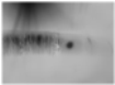
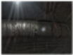
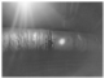
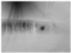
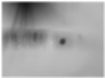
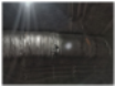
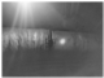
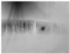
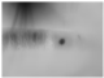
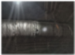
According to Equation (6), the algorithm proposed by He et al. [18] constructs the dark channel by first taking the minimum across the RGB channels and then applying a local minimum filter. The top 0.1% of pixels with the highest dark-channel values are selected, and atmospheric light A is estimated from the maximum intensity among the corresponding pixels in the input image. The initial transmission is then estimated and refined. Two important adjustment parameters are used: ω controls the dehazing strength and residual haze by modifying the initial transmission, while t0 imposes a lower bound on transmission during reconstruction to limit error amplification at low transmission values. The baseline experiment adopts the original parameter settings (rz = 15, ω = 0.95, t0 = 0.1) [18] , where rz denotes the side length of the dark-channel neighborhood, corresponding to an initial neighborhood of 15 × 15 pixels [18]. Guided filtering is used to replace soft matting for transmission refinement, and its neighborhood radius rk also influences the restoration result. Here, rz and rk control the spatial scales of dark-channel estimation and transmission refinement, respectively, whereas ω adjusts the dehazing strength and t0 constrains the reconstruction gain at low transmission values; their distinct roles therefore require separate sensitivity analysis. A controlled experiment is conducted by varying one parameter at a time, with input pixel values normalized consistently. The influence of the dark-channel neighborhood side length rz is examined first, and the corresponding results are presented in Table 3.

Table 3.
Runtime of atmospheric-light estimation at different image sizes.
| Image size | Pixel count (MP) | Global sorting (s) | Random sampling (s) |
| 456 × 342 | 0.156 | 0.00725 | 0.00010 |
| 912 × 684 | 0.624 | 0.02281 | 0.00022 |
| 1824 × 1368 | 2.495 | 0.09067 | 0.00086 |
| 2736 × 2052 | 5.614 | 0.20741 | 0.00237 |
| 3648 × 2736 | 9.980 | 0.49164 | 0.00482 |
Table 3.
Influence of Different Minimum Filter Radii on Image Restoration Performance.
| Parameters | Calibration Calculation Chart | ||||
|
rz=3 Ac=0.95 t0=0.1 rk=200 |
|
||||
| (a) Dark channel map | (b)Coarse transmittance map | (c) Optimized transmittance map | (d) Output map | ||
|
rz=15 Ac=0.95 t0=0.1 rk=200 |
|
||||
| (e) Dark channel map | (f) Coarse transmittance map | (g) Optimized transmittance map | (h) Output map | ||
|
rz=30 Ac=0.95 t0=0.1 rk=200 |
|
||||
| (i) Dark channel map | (j) Coarse transmittance map | (k) Optimized transmittance map | (l) Output map | ||
It can be observed from the three output maps (d), (h), and (l) in Table 1 that the overall brightness of the output image is gradually increased with the increase of the radius of the minimum value filter, while the defogging effect is gradually weakened. From the dark channel map, a larger radius of filtering leads to a larger area of dark squares, and some of the brighter pixels are blocked, resulting in the overall darkness of the dark channel. According to Eq. (5), the calculated transmittance is on the high side; because the atmospheric light valueAc is set as a fixed value in the experiment, combined with Eq. (6), the final output image is on the low side of the overall brightness, which is manifested as a darker image and the effect of defogging is not. It is worth noting that the atmospheric light value Ac is not fixed, but is calculated dynamically according to the actual image, and if Ac is small due to blocking, it will further affect the defogging results.
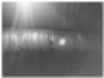
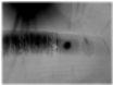
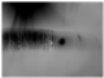
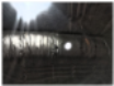
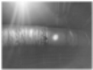
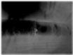
In order to deeply investigate the nature of atmospheric light value Ac on the effect of defogging and its mechanism of action, this study adds a control variable experiment, which artificially sets Ac to two sets of low value parameters, 0.7 and 0.5, respectively, and the rest of the parameters remain unchanged. The experimental results are shown in Table 4, (d), (h) the atmospheric light value in the output map shows a negative correlation with the output image brightness, when Ac, the transmittance map is underestimated due to the model constraints calculation, which leads to an abnormal elevation of the overall brightness of the image after defogging. However, this brightness enhancement is accompanied by a significant cost, with the image as a whole showing deterioration in color fidelity, reduced visual comfort, and strong halos in the bright regions. This experimental phenomenon triggers new thoughts on the calculation of atmospheric light values in complex downhole conditions.
Table 4.
Influence of Different Atmospheric Light Values on Image Restoration Performance.
| Parameters | Calibration Calculation Chart | |||
|
rz=3 Ac=0.7 t0=0.1 rk=200 |
|
|||
| (a) Dark channel map | (b) Coarse transmittance map | (c) Optimized transmittance map | (d) Output map | |
|
rz=3 Ac=0.5 t0=0.1 rk=200 |
|
|||
| (e) Dark channel map | (f) Coarse transmittance map | (g) Optimized transmittance map | (h) Output map | |
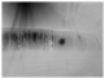
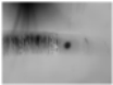
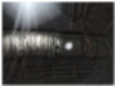
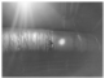
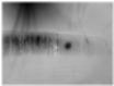
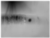
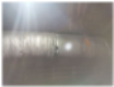
According to the preceding analysis, the calculation of the transmittance map not only affects the brightness of the output image but also directly determines the degree of defogging. To further verify this relationship, another set of control-variable experiments was designed. The lower limit of the transmittance map, t0 , was constrained and artificially raised to 0.5 and 0.9, respectively, while the remaining parameters were kept unchanged. This setting allows the influence of t0 on both defogging strength and brightness to be examined under otherwise identical conditions. The experimental results show that an excessively high lower limit of transmittance leads to insufficient image recovery, as evidenced by obvious residual haze and reduced overall contrast. This occurs because a large t0 restricts the attenuation of the transmittance term, thereby weakening the removal of scattering effects. In contrast, a moderate lower transmittance limit can effectively enhance the defogging effect. Meanwhile, a larger lower limit t0 is accompanied by an improvement in the overall brightness of the image, indicating that t0 regulates both the residual haze and the luminance level of the restored result. Therefore, the selection of t0 should balance defogging strength against brightness and potential over-enhancement. The detailed parameters used in the experiment and the calculation results are shown in Table 5.
In summary, the choice of the minimum filter radius not only directly determines the degree of detail retention in the dark channel map, but also indirectly affects the accurate extraction of atmospheric light values. A smaller filter radius can more accurately reflect the distribution of dark pixels in the local area, which helps to capture the image details; while a larger filter radius will mask the real dark channel features, resulting in a biased estimation of the atmospheric light value. As a key parameter in the defogging algorithm, the accuracy of the atmospheric light value directly affects the calculation of the transmittance map. If the atmospheric light value is overestimated, the transmittance map will be overall low, resulting in insufficient brightness and defogging of the output image; on the contrary, if the atmospheric light value is low, the transmittance map will be high, and the output image will be overly bright and the defogging effect will be weakened. The lower limit of the transmittance map further affects the brightness of the final fog-free image and the degree of defogging. Therefore, in the process of parameter selection, it is necessary to consider the filter radius, atmospheric light value and the lower limit of the transmittance and other factors, weighing the fogging intensity and the image, so as to avoid image distortion or insufficient fogging due to improper setting of a single parameter.
4.3. Analysis of Multiscale Transmittance Parameters
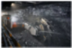
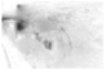
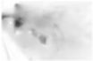
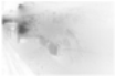
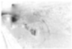
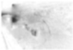
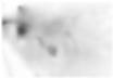
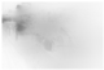
As shown in Table 6, the guided-filter scale rk controls the spatial range over which the transmission map is smoothed [20] , whereas the regularization parameter ε controls the sensitivity of the filter to local intensity variations. When ε is increased to 0.1, the transmission map becomes excessively smooth and some edges and fine structures are suppressed. In contrast, ε = 0.001 reduces local transmission fluctuations while retaining the principal structural boundaries; therefore, ε = 0.001 is used in the subsequent experiments.
The above results indicate that a single filtering scale cannot simultaneously achieve local-detail preservation and large-range transmittance continuity. To address this issue, three filter radii r = 15, 60, and 200 are adopted in this paper, corresponding to small, medium, and large spatial scales, respectively. Specifically, the small scale is mainly utilized to preserve local edges and detailed information, the medium scale balances local structures and regional smoothness, and the large scale improves the continuity of transmittance over a large spatial range. Through comprehensive comparison of transmittance outputs from different scales, obvious complementarity can be observed among the three scales. Accordingly, weighted fusion is further performed on these multi-scale results instead of adopting the filtered output from a single scale.
Considering that dust scattering and non-uniform illumination in underground mine images generally exhibit slow variations over extensive regions, larger weights are assigned to the large-scale transmittance map during fusion to enhance global spatial continuity. Meanwhile, medium- and small-scale components are retained to prevent edges and local textures from being over-smoothed. Combined with the multi-scale comparison results in Table 6 and the practical restoration performance on typical mine images, the fusion weights for the three scales are experimentally set to β = [0.7,0.2.0.1] with corresponding radii r = [200,60,15]. The final multi-scale fused transmittance map is illustrated in Figure 6. It can be seen that compared with single-scale filtering, the fused transmittance map maintains favorable preservation of major structural boundaries while retaining overall smoothness, which provides more stable transmittance estimation for subsequent image restoration.
5. Image Enhancement and Downstream Task Performance Evaluation
5.1. Effectiveness Evaluation
To evaluate the proposed method under underground mining imaging conditions, six actual mine scenes with distinct degradation characteristics were selected from the collected dataset, as summarized in Figure 8. These scenes represent typical underground visual monitoring conditions, including low illumination, spatially non-uniform lighting, strong artificial light interference, haze induced by dust, and mixed degradation. The comparative methods encompass conventional enhancement techniques (Retinex, MSRCR, CAP, and DCP) and deep learning–based approaches (MixDehazeNet, DehazeSNN, and HistoFusionNet).
As shown in Figure 8, the responses of the comparative methods to the complex illumination degradation present in underground scenes vary considerably. Retinex and MSRCR improve visibility in low-illumination regions, yet evident local contrast enhancement is observed in certain scenes containing intense artificial light sources. CAP and DCP alleviate partial dust–haze interference, but underexposure persists in some low-illumination areas. The learning-based methods achieve effective image restoration under certain circumstances; however, their performance fluctuates when severe non-uniform illumination coexists with dense dust haze. In contrast, the method proposed herein consistently yields a more balanced restoration of scene visibility and structural detail across all test scenes.
Three complementary no-reference metrics, namely Average Gradient, Edge Density((Number of Canny edge pixels / Total number of image pixels) × 100%), and the Natural Image Quality Evaluator (NIQE), were employed for objective evaluation. Average Gradient reflects local intensity variations and the visibility of image details. A higher value generally indicates richer texture and clearer local details, although an excessively high value may also be associated with noise amplification or over-enhancement. Edge Density is defined as the percentage of Canny edge pixels relative to the total number of image pixels and is used to measure the amount of distinguishable structural edge information. NIQE evaluates image quality based on natural scene statistics, with a lower value indicating a smaller statistical deviation from natural images. Since these three metrics characterize different aspects of image quality, including detail, structural information, and naturalness, they were jointly considered in the evaluation.
Table 7 reports the average results obtained by different methods over six representative underground mine scenes. MSRCR achieves the highest Average Gradient of 16.061, indicating strong enhancement of local intensity variations and contrast. However, relatively pronounced local contrast enhancement can also be observed in several scenes in Figure 7; therefore, Average Gradient alone is insufficient for assessing overall image quality. The proposed method obtains an Average Gradient of 8.606, while achieving the highest Edge Density of 14.072% and the lowest NIQE score of 3.279 among all compared methods. Compared with the input images, Edge Density increases from 10.551% to 14.072%, corresponding to an improvement of approximately 33.4%, while NIQE decreases from 4.175 to 3.279, corresponding to a reduction of approximately 21.5%. These results indicate that more structural edges are preserved and revealed after enhancement, while the natural-scene statistical characteristics of the images are also improved. Together with the visual comparisons in Figure 7, the results show that the proposed method improves the visibility of object contours and local details under complex underground illumination and dust-haze conditions while maintaining good image naturalness.
5.2. Effectiveness Evaluation of Intelligent Mine Monitoring
To evaluate the impact of image enhancement on intelligent mine monitoring tasks, person detection and pose estimation tests were conducted using YOLOv8s, YOLOv8n, YOLO11s, and YOLO11n under light fog and dense fog scenarios, as shown in Figure 8.
In the lightly foggy scene shown in Figure 8A, YOLOv8s detects the actual miner but also incorrectly identifies the suspended component in the upper-left region as a person, indicating that light fog and complex illumination can interfere with model performance. Image enhancement eliminates this false detection. YOLOv8n misses the miner in the original image but successfully detects the target after enhancement, suggesting that enhanced image features facilitate target recognition. In the enhanced image, YOLO11s detects the actual miner but also misidentifies the ground region on the right as another person. YOLO11n successfully detects the miner both before and after enhancement. These results indicate that, under light fog, image enhancement can correct some missed and false detections, although the enhanced features may also introduce new false detections.
In the dense-fog scene shown in Figure 8B, YOLOv8s, YOLOv8n, and YOLO11s detect the miner in the original image, although the skeleton keypoints predicted by YOLOv8n are misaligned, and YOLO11n produces a missed detection. After enhancement, the confidence scores of YOLOv8s and YOLO11s increase from 0.50 and 0.52 to 0.80 and 0.74, respectively. YOLO11n also changes from a missed detection to a successful detection. In contrast, YOLOv8n changes from incorrect skeleton localization in the original image to a missed detection after enhancement, indicating that YOLOv8n has relatively limited adaptability to image enhancement in this dense-fog scene.
Overall, image enhancement improves the person-detection performance of most models in both lightly and densely foggy scenes, with a more evident improvement under dense fog. However, enhancement may also introduce false detections. Therefore, additional decision rules or temporal consistency constraints should be incorporated in subsequent applications to reduce the impact of such errors.
6. Conclusions
This study presents a scene-oriented adaptation of the classical dark channel prior for underground mine images affected by dust haze and non-uniform illumination. Dark-channel estimation is performed in the V component of HSV space, together with a revised atmospheric-light sampling strategy and multiscale guided-filter refinement and fusion of transmission. These modifications separate luminance processing from chrominance and combine local structural information with regional transmission continuity, addressing the coexistence of poorly illuminated areas and intense local light sources. The revised atmospheric-light estimation procedure reduces its component-level computational cost. Representative personnel-detection comparisons further suggest that enhancement can improve target visibility in some degraded scenes, but the observed benefit depends on the scene and detector. The current evaluation is limited to selected mine scenes and primarily uses no-reference image-quality measures. Future work will investigate adaptive parameter selection and evaluate enhancement and personnel detection on larger annotated mine datasets and continuous video sequences, with particular attention to temporal consistency and deployment efficiency.
Author Contributions
Conceptualization, Y.-Q.W.; Methodology, Y.-L.L.; Validation, Y.-Q.W.; Resources, Y.-L.L.; Data curation, T.-Q. and Z.-W.C.; Writing—original draft, Y.-Q.W.; Writing—review and editing, Y.-Q.W. and Z.-W.C.; Supervision, Y.-L.L.; Funding acquisition, Y.-L.L. All authors have read and agreed to the published version of the manuscript.
Funding
This study was financed by the Heilongjiang Provincial Natural Science Foundation of China (Grant No. JQ2025E012).
Data Availability Statement
The original contributions presented in this study are included in the article. Further inquiries can be directed to the author Yueqing Wang (E-mail: xiaoqingw778@gmail.com).
Conflicts of Interest
The authors declare no conflicts of interest.
References
- Zhang, Y.; Zhang, J.; Guo, X. Kindling the darkness: A practical low-light image enhancer. In Proceedings of the 27th ACM International Conference on Multimedia, Nice, France, 21–25 October 2019; pp. 1632–1640. [Google Scholar] [CrossRef]
- Jiang, Y.; Gong, X.; Liu, D.; Cheng, Y.; Fang, C.; Shen, X.; Yang, J.; Zhou, P.; Wang, Z. EnlightenGAN: Deep light enhancement without paired supervision. IEEE Trans. Image Process. 2021, 30, 2340–2349. [Google Scholar] [CrossRef] [PubMed]
- Zamir, S.W.; Arora, A.; Khan, S.; Hayat, M.; Khan, F.S.; Yang, M.-H. Restormer: Efficient transformer for high-resolution image restoration. In Proceedings of the IEEE/CVF Conference on Computer Vision and Pattern Recognition (CVPR), New Orleans, LA, USA, 18–24 June 2022; pp. 5728–5739. [Google Scholar] [CrossRef]
- Liu, R.; Ma, L.; Zhang, J.; Fan, X.; Luo, Z. Retinex-inspired unrolling with cooperative prior architecture search for low-light image enhancement. In Proceedings of the IEEE/CVF Conference on Computer Vision and Pattern Recognition (CVPR), Nashville, TN, USA, 20–25 June 2021; pp. 10556–10565. [Google Scholar] [CrossRef]
- Cai, Y.; Bian, H.; Lin, J.; Wang, H.; Timofte, R.; Zhang, Y. Retinexformer: One-stage Retinex-based transformer for low-light image enhancement. In Proceedings of the IEEE/CVF International Conference on Computer Vision (ICCV), Paris, France, 1–6 October 2023; pp. 12470–12479. [Google Scholar] [CrossRef]
- Yi, X.; Xu, H.; Zhang, H.; Tang, L.; Ma, J. Diff-Retinex: Rethinking low-light image enhancement with a generative diffusion model. In Proceedings of the IEEE/CVF International Conference on Computer Vision (ICCV), Paris, France, 1–6 October 2023; pp. 12268–12277. [Google Scholar] [CrossRef]
- Song, Y.; He, Z.; Qian, H.; Du, X. Vision transformers for single image dehazing. IEEE Trans. Image Process. 2023, 32, 1927–1941. [Google Scholar] [CrossRef] [PubMed]
- Potlapalli, V.; Zamir, S.W.; Khan, S.; Khan, F.S. PromptIR: Prompting for all-in-one image restoration. Adv. Neural Inf. Process. Syst. 2023, 36, 71275–71293. [Google Scholar] [CrossRef]
- Li, H.; Chen, X.; Dong, J.; et al. Foundir: Unleashing million-scale training data to advance foundation models for image restoration[C]//2025 IEEE/CVF International Conference on Computer Vision (ICCV). IEEE 2025, 12626–12636. [Google Scholar] [CrossRef]
- Meng, G.; Wang, Y.; Duan, J.; Xiang, S.; Pan, C. Efficient image dehazing with boundary constraint and contextual regularization. In Proceedings of the IEEE International Conference on Computer Vision (ICCV), 2013; pp. 617–624. [Google Scholar] [CrossRef]
- Mohammed, I.M.; Isa, N.A.M. Contrast limited adaptive local histogram equalization method for poor contrast image enhancement. IEEE Access 2025, 13, 62600–62632. [Google Scholar] [CrossRef]
- Agrawal, S.; Panda, R.; Mishro, P.K.; Abraham, A. A novel joint histogram equalization based image contrast enhancement. J. King Saud University–Computer Inf. Sci. 2022, 34, 1172–1182. [Google Scholar] [CrossRef]
- Land, E.H.; McCann, J.J. Lightness and Retinex theory. J. Opt. Soc. Am. 1971, 61, 1–11. [Google Scholar] [CrossRef] [PubMed]
- Jobson, D.J.; Rahman, Z.; Woodell, G.A. Properties and performance of a center/surround Retinex. IEEE Trans. Image Process. 1997, 6, 451–462. [Google Scholar] [CrossRef] [PubMed]
- Jobson, D.J.; Rahman, Z.; Woodell, G.A. A multiscale Retinex for bridging the gap between color images and the human observation of scenes. IEEE Trans. Image Process. 1997, 6, 965–976. [Google Scholar] [CrossRef] [PubMed]
- Rahman, Z.; Jobson, D.J.; Woodell, G.A. Retinex processing for automatic image enhancement. J. Electron. Imaging 2004, 13, 100–110. [Google Scholar] [CrossRef]
- McCartney, E.J. Optics of the Atmosphere: Scattering by Molecules and Particles; John Wiley & Sons: New York, NY, USA, 1976. [Google Scholar]
- He, K.; Sun, J.; Tang, X. Single image haze removal using dark channel prior. IEEE Trans. Pattern Anal. Mach. Intell. 2011, 33, 2341–2353. [Google Scholar] [CrossRef] [PubMed]
- Zhu, Q.; Mai, J.; Shao, L. A fast single image haze removal algorithm using color attenuation prior. IEEE Trans. Image Process. 2015, 24, 3522–3533. [Google Scholar] [CrossRef] [PubMed]
- He, K.; Sun, J.; Tang, X. Guided image filtering. IEEE Trans. Pattern Anal. Mach. Intell. 2013, 35, 1397–1409. [Google Scholar] [CrossRef] [PubMed]
- Berman, D.; Treibitz, T.; Avidan, S. Non-local image dehazing. In Proceedings of the IEEE Conference on Computer Vision and Pattern Recognition (CVPR), 2016; pp. 1674–1682. [Google Scholar] [CrossRef]
- Lu, L.; Xiong, Q.; Xu, B.; Chu, D. MixDehazeNet: Mix structure block for image dehazing network. In Proceedings of the 2024 International Joint Conference on Neural Networks (IJCNN), 2024; pp. 1–10. [Google Scholar] [CrossRef]
- Li, H.; Liu, H.; Liu, M.; Xiao, Y.; Li, P.; Zan, G. U-Net-like spiking neural networks for single image dehazing. In Proceedings of the 2025 International Joint Conference on Neural Networks (IJCNN), 2025; pp. 1–9. [Google Scholar] [CrossRef]
- Heydari, M.; Dong, W.; Shirani, S.; Chen, J.; Zhou, H. HistoFusionNet: Histogram-guided fusion and frequency-adaptive refinement for nighttime image dehazing. In Proceedings of the IEEE/CVF Conference on Computer Vision and Pattern Recognition (CVPR) Workshops, 2026; pp. 1914–1924. [Google Scholar]
- Cai, B.; Xu, X.; Jia, K.; Qing, C.; Tao, D. DehazeNet: An end-to-end system for single image haze removal. IEEE Trans. Image Process. 2016, 25, 5187–5198. [Google Scholar] [CrossRef] [PubMed]
- Li, B.; Peng, X.; Wang, Z.; Xu, J.; Feng, D. AOD-Net: All-in-one dehazing network. In Proceedings of the IEEE International Conference on Computer Vision (ICCV), 2017; pp. 4770–4778. [Google Scholar] [CrossRef]
- Ren, W.; Liu, S.; Zhang, H.; Pan, J.; Cao, X.; Yang, M.-H. Single image dehazing via multi-scale convolutional neural networks. In Computer Vision–ECCV 2016; Springer International Publishing: Cham, Switzerland, 2016; pp. 154–169. [Google Scholar] [CrossRef]
- Engin, D.; Genç, A.; Ekenel, H.K. Cycle-Dehaze: Enhanced CycleGAN for single image dehazing. In Proceedings of the IEEE/CVF Conference on Computer Vision and Pattern Recognition Workshops (CVPRW), 2018; pp. 938–946. [Google Scholar] [CrossRef]
- Ullah, H.; Muhammad, K.; Irfan, M.; Anwar, S.; Sajjad, M.; Imran, A.S.; de Albuquerque, V.H.C. Light-DehazeNet: A novel lightweight CNN architecture for single image dehazing. IEEE Trans. Image Process. 2021, 30, 8968–8982. [Google Scholar] [CrossRef] [PubMed]
- Zhu, H.; Peng, X.; Chandrasekhar, V.; Li, L.; Lim, J.-H. DehazeGAN: When image dehazing meets differential programming. In Proceedings of the Twenty-Seventh International Joint Conference on Artificial Intelligence (IJCAI), 2018; pp. 1234–1240. [Google Scholar] [CrossRef] [PubMed]
- Tian, F.; Wang, M.; Liu, X. Low-light mine image enhancement algorithm based on improved Retinex. Appl. Sci. 2024, 14, 2213. [Google Scholar] [CrossRef]
- Wu, C.; Wang, D.; Huang, K.; Wu, L. Enhancement of mine images through reflectance estimation of V channel using Retinex theory. Processes 2024, 12, 1067. [Google Scholar] [CrossRef]
- Guo, C.; Li, C.; Guo, J.; Loy, C.C.; Hou, J.; Kwong, S.; Cong, R. Zero-reference deep curve estimation for low-light image enhancement. In Proceedings of the IEEE/CVF Conference on Computer Vision and Pattern Recognition (CVPR), 2020; pp. 1780–1789. [Google Scholar] [CrossRef]
- Du, Q.; Zhang, S.; Wang, Z.; Liang, J.; Yang, S. A hybrid zero-reference and dehazing network for joint low-light underground image enhancement. Sci. Rep. 2025, 15, 10135. [Google Scholar] [CrossRef] [PubMed]
- Li, Y.; Tian, J.; Chen, Y.; Wang, H.; Yan, H.; Peng, Y.; Wang, T. Rw-Dm: Retinex and wavelet-based diffusion model for low-light image enhancement in underground coal mines. Complex Intell. Syst. 2025, 11, 327. [Google Scholar] [CrossRef]
- Fan, Y.; Mao, S.; Li, M.; Yang, B.; Yang, Y. Adaptive multi-channel dehazing for enhanced visibility in underground coal mine images. PLoS ONE 2025, 20, e0334251. [Google Scholar] [CrossRef] [PubMed]
- Su, C.; Xiang, D.B.; Zhao, L.L.; Meng, J.Q.; Lu, J. An image dehazing algorithm for underground coal mine environments based on dual-channel prior and adaptive contrast enhancement. IET Image Process. 2026, 20, e70321. [Google Scholar] [CrossRef]
Figure 2.
Visual comparison of different enhancement methods on real-world underground mine images captured by industrial cameras (4080 × 3060). (A) Roadway scene with dust-induced scattering and non-uniform illumination. (B) Mining scene under low illumination and strong artificial lighting.
Figure 2.
Visual comparison of different enhancement methods on real-world underground mine images captured by industrial cameras (4080 × 3060). (A) Roadway scene with dust-induced scattering and non-uniform illumination. (B) Mining scene under low illumination and strong artificial lighting.
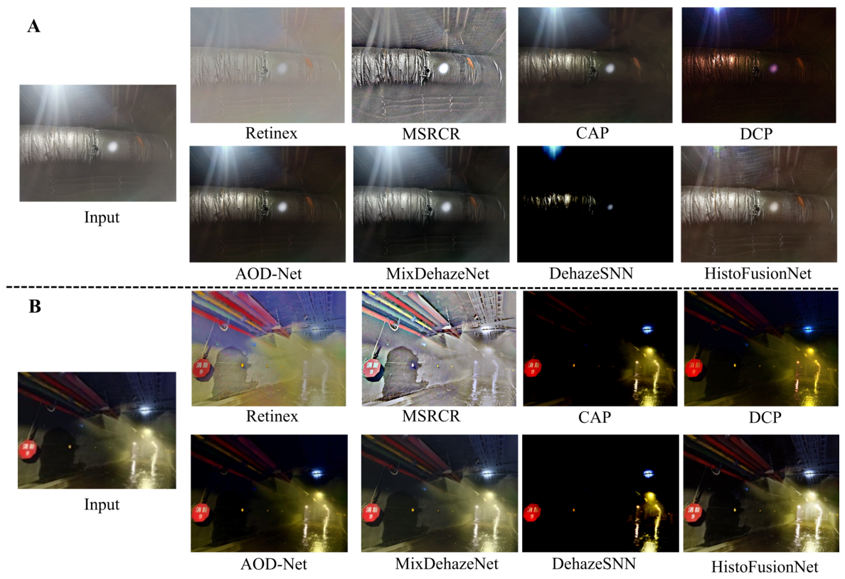
Figure 4.
Overall framework of the proposed HSV-DCP global correction method for underground mine image enhancement. The main processing stages are: (1) HSV color-space conversion with preservation of the H and S components; (2) morphological erosion of the V channel to construct the dark channel; (3) atmospheric-light estimation using random sampling and threshold constraint; (4) coarse transmission estimation and multi-scale guided-filter refinement; and (5) V-channel recovery, Gamma correction.
Figure 4.
Overall framework of the proposed HSV-DCP global correction method for underground mine image enhancement. The main processing stages are: (1) HSV color-space conversion with preservation of the H and S components; (2) morphological erosion of the V channel to construct the dark channel; (3) atmospheric-light estimation using random sampling and threshold constraint; (4) coarse transmission estimation and multi-scale guided-filter refinement; and (5) V-channel recovery, Gamma correction.
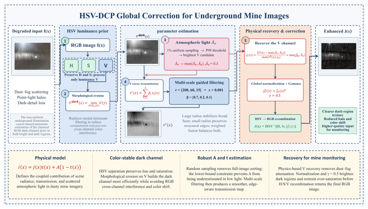
Figure 5.
Restoration results of the proposed method with different gamma values for the scene in Figure 2A and Figure 3 Scene B: (a) γ = 0.3, (b) γ = 0.5, (c) γ = 0.7, and (d) γ = 1. The parameter γcontrols the brightness and contrast of the output, with (c) yielding the best visual balance.
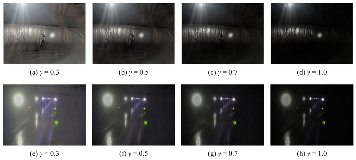
Figure 6.
Influence of the atmospheric light lower-bound parameter on enhancement. (a) Input image with dark and low-contrast regions; (b) Enhancement results with different values. An underestimated value (e.g., 0.1, 0.2) leads to local glare and loss of structural details, while an overestimated value (e.g., 0.4, 0.5) results in insufficient enhancement. achieves the best visual balance.
Figure 6.
Influence of the atmospheric light lower-bound parameter on enhancement. (a) Input image with dark and low-contrast regions; (b) Enhancement results with different values. An underestimated value (e.g., 0.1, 0.2) leads to local glare and loss of structural details, while an overestimated value (e.g., 0.4, 0.5) results in insufficient enhancement. achieves the best visual balance.
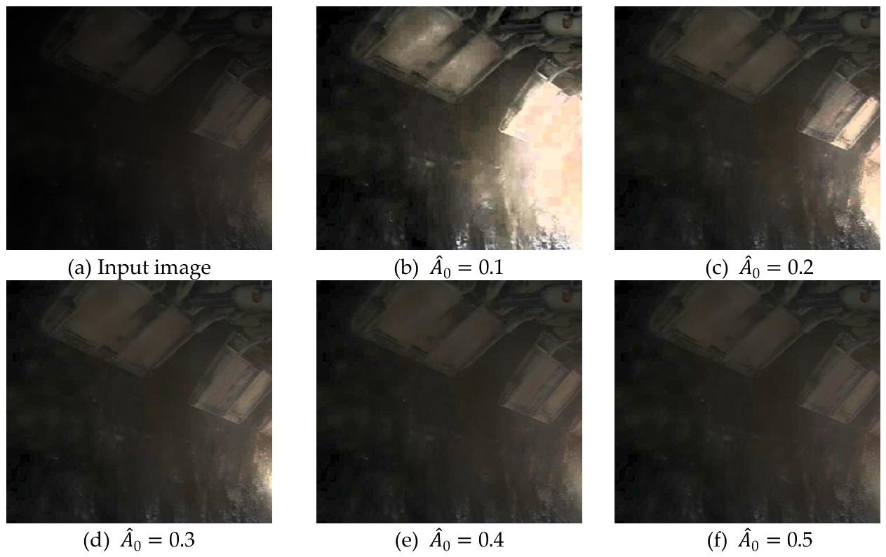
Figure 7.
Multi-scale transmission map obtained by guided-filter refinement and weighted fusion. Transmission maps at large, medium, and small scales r = [200,60,15] are fused with weights β = [0.7,0.2.0.1] under ε=0.001, providing improved spatial smoothness while preserving major structural boundaries.
Figure 7.
Multi-scale transmission map obtained by guided-filter refinement and weighted fusion. Transmission maps at large, medium, and small scales r = [200,60,15] are fused with weights β = [0.7,0.2.0.1] under ε=0.001, providing improved spatial smoothness while preserving major structural boundaries.
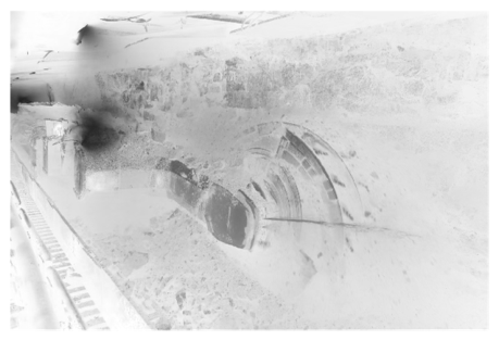
Figure 8.
Visual comparison of different image enhancement and dehazing methods across representative underground mine scenes with complex illumination and dust haze. The compared methods include Retinex, MSRCR, CAP, DCP, MixDehazeNet, DehazeSNN, HistoFusionNet, and the proposed method.
Figure 8.
Visual comparison of different image enhancement and dehazing methods across representative underground mine scenes with complex illumination and dust haze. The compared methods include Retinex, MSRCR, CAP, DCP, MixDehazeNet, DehazeSNN, HistoFusionNet, and the proposed method.
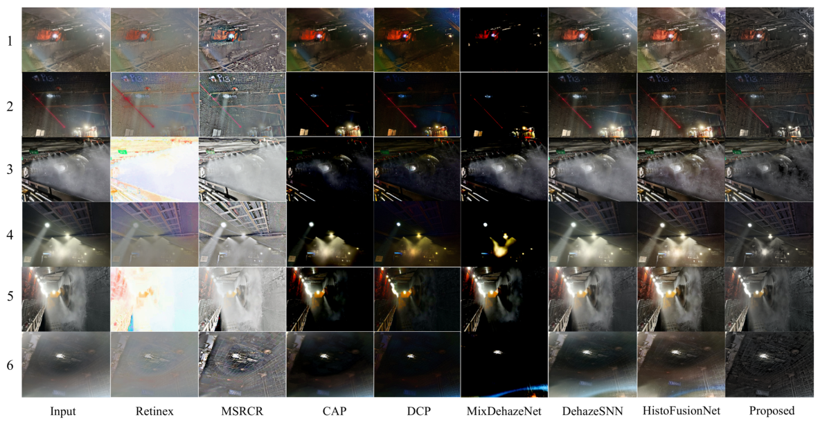
Figure 8.
Comparison of person detection performance on original and enhanced mine images under different dust-fog conditions using four YOLO models. (A) Foggy working-face scene; (B) dense-fog working-face scene.
Figure 8.
Comparison of person detection performance on original and enhanced mine images under different dust-fog conditions using four YOLO models. (A) Foggy working-face scene; (B) dense-fog working-face scene.
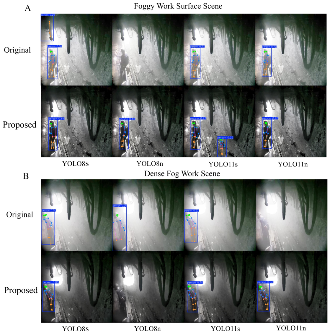
Table 1.
Overall Procedure of the Proposed Underground Mine Image Enhancement Method.
| Algorithm 1: Proposed Underground Mine Image Enhancement Method | |
| Input: degraded RGB image I(x); erosion window s; filtering radii r; fusion weights β; regularization parameter ε. | |
| Output: enhanced image J. | |
| 1 | Convert I from RGB to HSV color space and extract the value component V; |
| 2 | Compute the eroded value map Vₑ ← Erode(V, s); |
| 3 | Estimate the atmospheric-light parameter A and the initial transmission map t̃; |
| 4 | for i = 1, 2, 3 do |
| 5 | |
| 6 | end |
| 7 | Fuse the multi-scale transmission maps: ᵢ; |
| 8 | Recover the scene radiance J using the refined transmission map tr(x) |
| 9 | Apply adaptive illumination correction to J to obtain the final enhanced image J(x) |
| 10 | return Jout. |
Table 2.
Comparison of Dark Channel Maps Obtained by Different Algorithms.
| Calculate the time required/S | dark Channel Map |
|
22.86 |
 (a) Traditional Dark Channel Prior [18] |
|
0.0702 |
 (b) Dark-channel of morphological corrosion |
Table 5.
Influence of Different Minimum Transmission Values on Image Restoration Performance.
| parameters | Calibration Calculation Chart | |||
|
rz=3 Ac=0.95 t0=0.5 rk=200 |
|
|||
| (a) Dark channel map | (b) Coarse transmittance map | (c) Optimized transmittance map | (d) Output map | |
|
rz=3 Ac=0.95 t0=0.9 rk=200 |
|
|||
| (e) Dark channel map | (f) Coarse transmittance map | (g) Optimized transmittance map | (h) Output map | |
Table 6.
Comparative Analysis of Transmission Maps at Multi-Scale.
| parameters | Calibration Calculation Chart | |||
|
ε=0.001 |
|
|||
| (a)Working surface diagram | (b) rk=15 | (c) rk=60 | (d) rk=200 | |
|
ε=0.1 |
|
|||
| (e) Coarse transmittance map | (f) rk=15 | (g) rk=60 | (h) rk=200 | |
Table 7.
Average no-reference metric results for six underground scenes.
| Method | Average Gradient | Edge Density (%) | NIQE |
| Input | 5.614 | 10.551 | 4.175 |
| Retinex | 5.105 | 11.230 | 3.940 |
| MSRCR | 16.061 | 13.544 | 4.076 |
| CAP | 5.484 | 6.456 | 7.144 |
| DCP | 6.786 | 8.373 | 4.263 |
| MixDehazeNet | 3.204 | 4.066 | 11.509 |
| DehazeSNN | 6.556 | 10.510 | 4.634 |
| HistoFusionNet | 10.518 | 11.669 | 6.940 |
| Proposed | 8.606 | 14.072 | 3.279 |
Disclaimer/Publisher’s Note: The statements, opinions and data contained in all publications are solely those of the individual author(s) and contributor(s) and not of MDPI and/or the editor(s). MDPI and/or the editor(s) disclaim responsibility for any injury to people or property resulting from any ideas, methods, instructions or products referred to in the content. |
© 2026 by the authors. Licensee MDPI, Basel, Switzerland. This article is an open access article distributed under the terms and conditions of the Creative Commons Attribution (CC BY) license (http://creativecommons.org/licenses/by/4.0/).
Copyright: This open access article is published under a Creative Commons CC BY 4.0 license, which permit the free download, distribution, and reuse, provided that the author and preprint are cited in any reuse.