
Submitted:
21 October 2026
Posted:
22 October 2026
You are already at the latest version
Abstract
This paper presents a thermodynamic and fluid-dynamic evaluation of superfluid helium (He-II) at 2.17 K within a non-chemical electromagnetic propulsion framework (AETHER). By coupling vortex-stabilized cryogenic expulsion with pulse-based thrust control, the architecture bypasses chemical combustion, utilizing He-II for high-flux thermal management while generating directional thrust via high-frequency electromagnetic acceleration of ionized helium plasma.
Keywords:
superfluid helium (He-II)
; cryogenic propulsion
; thermal management
; heat transport
; space propulsion systems
; propulsion system feasibility
; cryogenic heat loads
; thermal stability
1. Background
Contemporary space propulsion systems remain largely dependent on conventional chemical-based rocket systems. These systems suffer from several limitations such as producing chemically reactive exhaust plumes, having relatively low specific impulse, and lacking the efficiency required for long-duration or deep-space missions. To address this challenge, we propose an advanced space propulsion concept known as AETHER — Advanced Emission-less Thrust using Helium Ejection and Recovery.
2. Motivation
2.1. Limitations of Conventional Propulsion
Chemical propulsion has served as the primary method for space launch and orbital insertions. Although this technology has enabled early lunar and interplanetary missions, it comes with serious drawbacks. Traditional chemical rockets generate thrust by expelling high temperature gases generated from exothermic combustion reactions. This process is fundamentally limited by the thermodynamics of chemical bonds, restricting specific impulses to between 250 and 450 seconds [4]. It also introduces particulate and chemical contamination into the local spacecraft environment, which can degrade sensitive payloads. Furthermore, chemical propulsion systems are fundamentally constrained by the Tsiolkovsky rocket equation (), which mandates an exponential mass penalty for incremental velocity gains. These systems are poorly suited for long-duration, deep-space missions where sustained, efficient thrust is necessary over extended periods.
2.2. The Need for Non-Contaminating Deep Space Propulsion
Deep-space mission profiles present rigorous baseline performance requirements; such as higher specific impulse to reduce fuel mass; more precise and controllable thrust for orbital corrections and scientific payload positioning; close to emission-less operation to preserve delicate environments (e.g., near-space telescopes, space stations); and reliability over years without mechanical wear or chemical degradation.
While electric propulsion systems such as ion drives have made significant strides in this area, they suffer from low thrust levels and require heavy power systems [3]. There remains a technological gap for a propulsion system that is both non-contaminating and power-dense, especially for deep-space maneuvering.
2.3. Why Superfluid Helium?
To maintain the requisite sub-lambda point temperatures (below 2.17 K) in the thermal environment of space, AETHER employs a comprehensive thermal cascade architecture. This system utilizes deployable sun-shields and Multi-Layer Insulation (M.L.I) to passively reject external solar and internal bus radiation. To mitigate unavoidable heat leak, active sub-Kelvin cryo-coolers continuously extract thermal energy from the propellant tanks, rejecting this concentrated heat into space via dedicated radiator fins. Furthermore, to manage transient thermal loads, the system employs thermodynamic venting; a controlled fraction of the helium is allowed to absorb thermal energy and vaporize. This boil-off is expelled through a highly precise porous plug phase separator[12], which utilizes the latent heat of vaporization to provide robust evaporative cooling while preventing the loss of bulk liquid He-II in microgravity. The propulsion sequence itself operates in two distinct phases to maximize efficiency. Initially, the system leverages the zero-viscosity state of He-II to drive a thermomechanical (fountain effect) propellant feed into the chamber[1,2]. Subsequently, upon entering the reaction chamber, the superfluid state is intentionally broken via high-frequency electromagnetic energy injection (e.g., microwave or laser excitation), rapidly ionizing the helium into a high-energy plasma. This plasma is subsequently accelerated through a magnetic nozzle, achieving a specific impulse of approximately 1,529 seconds. By decoupling the frictionless quantum feed system from the high-energy electromagnetic expulsion, AETHER delivers a clean, power-dense, and highly controllable propulsion method ideally suited for long-duration deep-space operations.
3. AETHER System Architecture
The AETHER propulsion system is built around the exploitation of superfluid helium’s unique quantum mechanical properties, integrated with advanced cryogenics, vortex dynamics, and precision thrust control. It consists of several key subsystems operating synchronously to enable clean propulsion optimized for deep-space environments.
3.1. Cryogenic Cooling System
Stage 1 involves Passive Radiative Pre-Cooling; initial cooling to 40 K is achieved utilizing deployable sun-shields and deep-space geometry, completely bypassing the mass penalty of consumable pre-coolants.
Stage 2 features a Pulse-Tube Cryo-cooler; an active, closed-cycle pulse-tube cooler brings the temperature down to 4 K[6]. Operating with no moving parts at the cold head, this stage ensures high reliability and zero vibrational interference with the fluid dynamics.
Stage 3 is known as the Joule-Thomson Expansion Stage. To cross the lambda point and achieve sub-2.17 K temperatures, the system utilizes a Joule-Thomson expansion valve coupled with the porous plug phase separator. This provides the final temperature drop to maintain the He-II superfluid state.
The helium is stored in a vacuum-insulated dewar lined with multi-layer insulation (MLI), with the concentrated heat from the cryo-coolers rejected to deep space via dedicated radiator fins.
3.2. Superfluid Propellant Management
Superfluid helium (He-II) presents distinct propellant management challenges in microgravity. Because of its zero viscosity, it triggers the Rollin film effect, spontaneously creeping along the walls of its container. To keep the propellant confined, AETHER replaces traditional mechanical pumps. Instead, the primary flow relies on thermomechanical (fountain effect) capillary pumps, using microscopic thermal gradients to push the He-II into the engine chamber. To stop the superfluid from creeping through the feed lines when the engines are shut down, the system uses phase-isolated thermal traps. These traps locally heat the helium just above the lambda point, reverting it to a normal fluid and instantly halting the Rollin creep. Finally, instead of wasting the helium gas that boils off through the primary tank’s porous plug, AETHER captures it. This boil-off is routed directly into a secondary cold-gas Reaction Control System (RCS), providing auxiliary attitude control without imposing additional electrical load.
The thermomechanical (fountain) effect operates strictly as a thermally driven fluid drive; the required pressure gradient is actively maintained by introducing a controlled heat flux () sourced from reactor waste heat, fully adhering to second-law thermodynamic limits.
3.3. Vortex Nozzle Design
The AETHER engine core bridges the freezing He-II fuel and the high-enthalpy plasma exhaust using a swirling vortex chamber and a magnetic nozzle. Instead of pumping the He-II straight in, the system injects it tangentially to induce a high-velocity tangential vortex flow along the chamber wall. Centrifugal force confines the zero-viscosity fluid to the peripheral boundary via centrifugal acceleration, creating a freezing thermal shield that protects the physical engine housing from melting. Inside the low-pressure inner face of this vortex core, high-frequency electromagnetic waves energize the inner helium boundary layer, ionizing it into a high-temperature plasma. Direct contact between the high-temperature plasma core and physical metallic structures would result in immediate catastrophic wall ablation. To solve this, AETHER uses superconducting electromagnets to generate an axisymmetric converging-diverging magnetic field topology. This "magnetic de Laval nozzle" constricts the expanding plasma stream prior to divergent acceleration [5]. It acts exactly like a traditional physical nozzle, accelerating the plasma to extreme supersonic speeds, thereby maintaining zero physical or direct thermal contact with the structural components of the propulsion assembly.
3.3.1. Boundary Layer Thermal Dissipation
The physical wall of the chamber never touches the hot plasma. The swirling He-II layer is positioned coaxially between the physical wall and the plasma core. When the plasma radiates intense heat outward, that heat hits the inner face of the superfluid vortex stream. Instead of passing through to the wall, that inner layer of helium absorbs the heat and boils into a gas. This phase change (from liquid to gas) absorbs massive amounts of thermal energy. By the time the energy tries to travel through the spinning liquid, it has been completely dissipated. The He-II acts as a sacrificial, self-healing heat shield. To balance the electrical power architecture, the system implements a fractional ionization scheme, ionizing a small portion of the boundary fluid to maintain the plasma core while leaving the primary mass fraction as neutral gas. Furthermore, the high-field superconducting magnetic fields are tuned to reflect 99.9% of direct radiative heat flux, ensuring the residual thermal load remains within the liquid boundary layer’s latent vaporization cooling limit.
3.3.2. Structural Cryogenic Material Integrity
The wall is safely protected from the heat, but now it is in direct, constant contact with liquid He-II at roughly 2 Kelvin (-271°C). Constructing the chamber boundary from standard structural alloys would result in the extreme cold inducing severe cryogenic embrittlement, rendering standard structural alloys susceptible to fatigue failure. To withstand these extreme thermal gradients and mitigate cryogenic embrittlement, the containment chamber walls require high-strength superalloys, specifically Inconel 718 or a stabilized niobium-hafnium alloy. These specific materials maintain their structural integrity and do not become brittle even when pushed towards absolute zero.
Because liquid helium boils very easily, preventing rapid fuel loss requires keeping heat leakage to the liquid wall under 1 kilowatt. The engine achieves this through two protective layers: first, boiling helium creates a buffer of cold gas that acts as a heat shield against ultraviolet radiation; second, strong magnetic fields squeeze the hot plasma core into the center of the chamber, keeping it away from the walls. Furthermore, because the magnitude of density of superfluid helium is drastically greater than the plasma, the liquid only needs to creep along the wall at a slow macroscopic boundary flow of v = 2.7 cm/s to generate a 15,000 m/s plasma exhaust. This slow flow rate prevents turbulence and ensures that 50,000 kg of fuel lasts for 6.5 days of continuous firing.
3.4. Pulse Based Thrust Generation and Magnetic Steering
To control the spacecraft’s movement and manage heat, AETHER uses a pulsed thrust system. Instead of relying on mechanical valves which are prone to freezing and breaking in ultra-cold environments, the liquid helium flows into the engine continuously. Thrust is instead created by pulsing the central laser or microwave in rapid 10–100 millisecond bursts. This high-frequency pulsing regime thermally isolates the cold superfluid: the brief pauses between each energy pulse give the spacecraft’s cooling system time to clear out any excess heat. For the steering process, secondary electromagnets are used to deflect the magnetic field axis by switching them off and on. Bending this magnetic field redirects the hot plasma, steering the spacecraft with high precision,yielding a low absolute thrust level typical of high-efficiency electric propulsion systems. This combination of pulsing lasers and magnetic steering creates a highly reliable engine with zero moving parts. To manage this complex firing sequence, an integrated digital control loop continuously simulates the engine’s fluid dynamics, actively optimizing pulse timing and magnetic vectoring for the current mission phase.
Operational stability is established via a two-phase firing sequence. Prior to plasma ignition, a 20-second pre-ignition priming cycle injects tangential liquid helium to coat the inner walls with a uniform 2 cm liquid vortex. Once fully established, thrust is generated by pulsing the central energy source in 10–20 ms bursts (10–20 Hz). Each high-energy pulse flash-ablates a superficial micro-layer of the liquid film into ionized plasma. In the intervening 80–90 ms rest periods, the steady 2.7 cm/s liquid feed seamlessly replenishes the ablated layer, allowing the active cryo-coolers to clear residual thermal spikes. Vectoring is achieved by modulating secondary electromagnets to dynamically bend the magnetic exhaust plume, enabling precise thrust steering without dynamic mechanical components.
While a boundary layer appears thin on a structural scale, it represents a massive physical barrier on the atomic scale. Due to the high atom density of cold helium gas at the boundary, the mean free path for escaping plasma ions is less than . Any plasma ions diffusing sideways undergo thousands of energy-dampening collisions within the innermost fraction of a millimeter of the helium layer. Combined with helium’s extreme UV absorption capability ( threshold), the layer completely dissipates both particle kinetic energy and radiative thermal flux long before reaching the structural housing.
3.5. Nuclear Power Generation and Shielding
The AETHER engine requires a massive amount of electricity ( between 8 and 10 Megawatts ) to create the plasma, run the magnetic force fields, and keep the helium continuously frozen. Because sunlight is too weak in the deep solar system to rely on solar panels, the architecture must use a Nuclear Electric Propulsion (NEP) system. To generate this continuous power, the ship uses a compact nuclear fission reactor. The intense heat produced by the nuclear core is fed through a specialized closed-loop turbine system (known as a Brayton cycle), which efficiently converts the raw thermal heat directly into electrical current [8]. However, placing a high-temperature nuclear reactor in proximity to a cryogenic propellant reservoir creates a severe thermal and safety hazard. To solve this, the reactor is physically separated from the main body of the spacecraft. It is mounted at the very end of a long, extendable boom. Positioned immediately in front of the reactor is a thick, cone-shaped "shadow shield" built from radiation-absorbing materials like tungsten and lithium hydride. This shield establishes a conical radiation attenuation zone over the entire length of the spacecraft, ensuring that the ultra-cold helium fuel tanks, the superconducting magnets, and the crew cabin are completely protected from the reactor’s heat and radiation. While physical separation mitigates direct radiation, the extendable boom introduces severe structural and thermodynamic risks that must be actively managed. To choke conductive heat transfer along the structural boom that conducts the reactor’s residual heat into the cryogenic tanks, it is constructed as an open-lattice truss using rigid carbon-carbon composites. This is coupled with titanium and G-10 fiberglass thermal standoffs at the structural joints, which severely choke conductive heat transfer. Furthermore, this lightweight lattice design provides the extreme mechanical stiffness required to prevent the destructive structural resonance and low-frequency bending modes during Reaction Control System (RCS) steering maneuvers. Finally, to transmit 10 Megawatts of power across this boom while preventing ohmic degradation and excessive resistive heating, power is routed through triple-redundant, ultra-high-voltage transmission lines utilizing High-Temperature Superconductors (HTS). This ensures that the massive electrical load reaches the AETHER engine with near-zero ohmic heating, perfectly preserving the strict 2.17 K thermal environment of the main spacecraft. To handle the massive 10-Megawatt power supply, the spacecraft design groups fifty smaller (200-kW) electric engines at the aft structural bus. A primary parameter requiring detailed magnetohydrodynamic (MHD) modeling is the plume-plume interaction and magnetic field interference between adjacent nozzles in the array.
3.6. Risk Mitigation and Redundancy
To ensure operational viability over decade long deep-space mission architectures, the AETHER engine employs comprehensive, redundant fail-safes against both kinetic hazards and operational anomalies. To mitigate the risk of high-velocity micro-meteoroid impacts severing critical power umbilicals, the external reactor boom is sheathed in multi-layer Whipple shielding [10], supplemented by triple-redundant high-voltage transmission lines. The catastrophic risk of superconducting magnet quenching—a statistical failure mode for high-power magnetic nozzles—is addressed through the integration of High-Temperature Superconductors (HTS) possessing substantial thermal margins, actively protected by a secondary cryogenic helium bleed loop. Furthermore, operational hazards such as the acoustic "cryo-hammer" effect are prevented via automated bypass chill-down loops that thermally precondition the feed lines prior to main liquid flow. Long-term radiological degradation of the modular boom due to neutron bombardment is similarly mitigated through the use of highly transparent carbon-carbon composites. Together, these redundant architectures neutralize immediate probabilistic threats, user-error anomalies, and long-term material fatigue, ensuring continuous, uninterrupted thrust capability across extreme mission durations [13]. While propellant helium is permanently expelled to space to satisfy conservation of momentum, energy recovery within the AETHER architecture refers exclusively to internal closed-loop thermal recycling.
3.7. Vehicle Geometry and Thermal Design Limits
The system design uses a fixed 50-meter separation distance between the 10 MW nuclear power source and the cold helium tanks, connected by an open-lattice carbon frame. This 50-meter distance ensures that heat from the reactor naturally drops off before reaching the fuel, keeping heat leakage below the 1 kW limit required to protect the propellant. System startup assumes the tanks are initially empty in orbit, before being filled with liquid helium and cooled down to sub-2.17 K temperatures prior to engine ignition.
4. Performance Modeling
4.1. Specific Impulse and Exhaust Velocity
Specific impulse is a crucial measure of propulsion efficiency, defined as the thrust produced per unit weight flow of propellant. For AETHER, the ultimate exhaust velocity is achieved via electromagnetic acceleration of the ionized plasma. The initial injection and thermal protection velocities are dictated by quantum vortex theory, where the tangential circulation velocity ensures that:
By stabilizing the high-energy core with this ultra-cold, frictionless boundary, the engine can sustain extreme plasma temperatures without thermal failure. This mechanism enables a final axial exhaust velocity of 15,000 m/s. With 750 N of thrust at a mass flow rate of 0.05 kg/s, the specific impulse is calculated as 1529 seconds. This significantly exceeds traditional chemical propulsion (typically < 450 s) and bridges the gap between high-thrust chemical engines and highly efficient electric propulsion systems. Thermodynamic efficiency estimates reach approximately 85–90 percent at a 15,000 m/s exhaust velocity, benefiting heavily from the J/kg cooling enthalpy provided by the He-II vortex array[7].
4.2. Thermal and Cryogenic Load Modeling
The performance envelope of the AETHER engine is defined by the direct relationship between specific impulse, thrust, and electrical power. While the high exhaust velocities achieved by the plasma acceleration yield exceptional fuel efficiency, they require significant electrical power inputs. The thrust generated by the engine is a product of the propellant mass flow rate and the exhaust velocity:
To achieve the target thrust of 750 N, the corresponding kinetic power of the exhaust jet scales linearly with the exhaust velocity:
Accounting for system inefficiencies—including the ionization energy overhead, magnetic nozzle operation, and the thermodynamic work required by the cryo-coolers to maintain the He-II vortex—the total electrical power requirement scales to the 8–10 MW class. Assuming a baseline exhaust velocity () of 15,000 m/s (yielding a specific impulse, , of 1529 s), the required kinetic jet power () evaluates to exactly 5.625 MW under ideal expansion conditions. The core electromagnetic acceleration mechanism operates at a high individual thruster efficiency of 87.8%, requiring 6.4 MW of direct input.When accounting for auxiliary vehicle subsystems, including the 3.6 Megawatt (MW) of peak power for sub-Kelvin cryo-coolers for in-transit propellant thermal maintenance, feed-line chill-down, and system bus management, the total spacecraft power allocation would scale to 10.0 MW. During active firing, primary thermal dissipation would be represented by evaporative helium mass loss () from the vortex boundary layer and magnetic pressure reflection, versus closed-loop refrigeration.
4.3. Comparative Analysis
Compared to conventional propulsion systems, the AETHER architecture offers a combination of high thermodynamic efficiency, sustained continuous thrust, and propellant inertness. Traditional chemical rockets (e.g., or Kero/LOX), while capable of high immediate thrust, suffer from low specific impulse () and high propellant mass fractions, limiting their viability for continuous, long-duration deep-space missions. Conversely, while state-of-the-art electric propulsion systems (such as ion and Hall-effect thrusters) achieve high specific impulse (), they remain constrained by extreme thermal loss and low thrust-to-power scaling.
The AETHER architecture operates within this high-efficiency regime, delivering electric-class specific impulse (1,529 s) at low, highly controllable absolute thrust levels while operating entirely with inert helium plasma.
This offers distinct operational advantages over legacy electric propulsion architectures. For example, while traditional chemical and unshielded electric systems dissipate significant reaction energy as unrecoverable waste heat, AETHER’s closed-loop magnetic nozzle and He-II cryogenic boundary layer actively manage internal thermal flux. Utilizing the cooling enthalpy of the He-II vortex yields an estimated propulsive thermodynamic efficiency. The inert, non-reactive helium exhaust eliminates physical and chemical contamination risks to scientific payloads; leading to a cleaner operation.
4.4. Scope of Model Validity and Physical Limitations
The framework presented in this section serves as an idealized, first-order parametric scaling model. While the one-dimensional boundary conditions demonstrate macroscopic pressure and thermal equilibrium under the adopted assumptions, several multi-scale physical phenomena remain unaddressed.
First, the magnetohydrodynamic (MHD) confinement profile derived herein is strictly one-dimensional and assumes a perfectly symmetric plasma column. In a realistic three-dimensional geometry, high-energy helium plasmas are highly susceptible to macro-instabilities — such as kink (), sausage (), and resistive tearing modes. These instabilities cause localized distortions in the magnetic field lines, which would induce transient plasma sheaths to directly impinge upon the physical chamber walls, bypassing the bulk magnetic pressure () boundary.
Next, in physical reality, He-II exhibits a near-infinite effective thermal conductivity driven by internal quantum counterflow (the two-fluid model) and the propagation of second sound. Under an intense, multi-megawatt radiative flux governed by the Stefan-Boltzmann relation, heat transport would not remain confined to the innermost boundary layer. Instead, thermal energy would propagate through the entire fluid volume at the speed of sound, risking a systemic lambda-point crossing ( K) and subsequent explosive flash-boiling of the propellant core.
Third, this study treats the required plasma confinement pressure as a static, horizontal threshold ( Pa) and assumes an empirical attenuation factor () for the multi-layer insulation. A high-fidelity evaluation must incorporate dynamic, coupled Navier-Stokes and Maxwell solvers to map real-time micro-turbulences, Bohm diffusion scales, and parasitic structural heat leaks through structural standoffs.
Consequently, the 6.50-day continuous operational lifetime and the 1,335 N thrust profile reported in this work represent ideal upper bounds. This framework does not prove absolute engineering feasibility or validate a physical propulsion system. Instead, it establishes the minimum baseline thermodynamic boundaries necessary to constrain future mission profiles. Furthermore, the current framework assumes an idealized, fully ionized boundary layer that neglects neutral gas diffusion across the magnetic nozzle. In an operational environment, neutral helium atoms originating from the vapor shield phase would remain unaffected by the 3.72 T magnetic pressure barrier. The unhindered cross-field migration of these neutral species into the high-enthalpy core would trigger localized ionization cascades, significantly elevating radiation losses and potentially quenching the plasma core.
Additionally, the macroscopic stability of the 2 cm superfluid Helium-II (He-II) layer remains a critical theoretical constraint. Under the intense 10-MW radiative thermal flux of the core, the local heat load may exceed the critical heat flux threshold of the superfluid phase. Exceeding this limit would trigger immediate film boiling, destroying the macroscopic quantum state and inducing a transition to normal fluid helium (He-I).
Finally, the propellant feed loop assumes zero thermal back-conduction into the capillary plug matrix. In practice, strong thermal feedback from the reaction chamber would induce local vapor lock inside the porous manifold. This phase change would choke the thermomechanical fountain effect, resulting in immediate fuel starvation. Consequently, a highly complex, active refrigeration topology must be mapped out to maintain these strict sub-Kelvin boundaries.
5. Mission Applications
The AETHER propulsion system is well suited to positively affect space travel by offering clean, high-efficiency thrust in regimes where conventional chemical or electric propulsion systems face inherent limitations. Its high specific impulse, substantial absolute thrust, and its non-reactive exhaust profile makes it suitable for a wide spectrum of mission types, particularly in environments beyond Earth’s atmosphere. One of the primary applications of AETHER is in long-duration deep-space exploration. Traditional fuel constraints and emission concerns significantly limit mission scope for legacy systems. AETHER’s high-density superfluid helium propellant allows for extended operation without the thermal degradation or fuel exhaustion typical of combustion-based rockets. This makes AETHER an optimal candidate for heavy interplanetary transports or interstellar probes, where sustained, efficient propulsion is essential for reducing transit times and enabling dynamic mid-course corrections. The AETHER architecture is optimized for orbital maneuvering within high Earth orbit. Once safely deployed in high Earth orbit or beyond, the system can take over from chemical boosters, providing the sustained delta-v required for rapid interplanetary transfer burns and complex orbital insertions around distant bodies (e.g., Jovian or Saturnian moons) with minimal fuel mass penalty. In addition, magnetic vector control and the frictionless flow of its He-II cryogenic boundary layer enable ultra-precision maneuvering without the mechanical vibrations associated with turbopumps or combustion instability. This vibration-free, pulsed-thrust mode makes AETHER ideally suited for missions carrying highly sensitive scientific payloads, such as gravitational wave detectors, cryogenic space telescopes, and quantum communication interferometers. Furthermore, AETHER aligns perfectly with the strict requirements of planetary protection protocols. Its non-reactive, inert helium exhaust entirely avoids the biological and chemical contamination risks associated with toxic chemical propellants (e.g., hydrazine). As the space industry evolves toward long-term outposts in cislunar space and pristine extraterrestrial environments, it provides a clean, high architecture suitable for extended interplanetary mission profiles[11].
6. Engineering Challenges and Feasibility
While the AETHER architecture offers significant theoretical propulsive advantages, building it requires solving several extreme engineering challenges. Each part of the system pushes the boundaries of current aerospace technology.
6.1. Cryogenic Cooling in Zero Gravity
The primary technical constraint involves maintaining propellant thermal stability at . Because we cannot use heavy, consumable coolants like liquid nitrogen in deep space, the ship must rely on passive deep-space radiators to shed most of the heat for free. To reach the final freezing temperatures in zero gravity, standard laboratory coolers fail. Instead, AETHER must use magnetic cooling systems (Adiabatic Demagnetization Refrigerators), which operate effectively in microgravity environments but are difficult to scale up for a massive engine.
6.2. Superfluid Hydrodynamics and Containment
Liquid helium at this temperature exhibits non classical quantum fluid dynamics: it has completely zero friction and naturally creeps up the walls of its container to escape (known as the Rollin film effect). To stop the fuel from migrating in zero gravity, the storage tanks require specialized vacuum insulation and microscopic capillary traps to force the fluid exactly where it needs to go.
6.3. Nanoscale Manufacturing and Magnetic Interference
The engine’s internal vortex chamber requires sub-nanometer surface roughness tolerances; even a microscopic scratch could destabilize the swirling liquid helium wall. Additionally, the high field superconducting magnets used to steer the hot plasma exhaust create intense magnetic fields. These fields require heavy shielding so they do not accidentally interfere with or shut down the ship’s delicate freezing equipment.
6.4. Radiation-Hardened and Cryo-Tolerant Instrumentation
The engine uses advanced quantum sensors (atomic interferometers) to perfectly monitor the helium flow. However, the engine’s strong magnets will cause sensor saturation and drift unless wrapped in high-permeability magnetic shielding materials. Furthermore, the valves that pump the freezing helium must survive tens of thousands of uses. Standard mechanical parts freeze solid at 2 Kelvin, so AETHER must use custom superconducting magnetic valves capable of sustained cyclic operation in extreme cryogenic environments.
6.5. Development Roadmap and Technology Readiness
While engineering challenges remain, building AETHER is within the realm of possibility. By adapting proven technologies from current fusion research, particle accelerators, and quantum computers, the scientific foundation is already established. With focused interdisciplinary development, a working ground-test prototype could be constructed and validated within the next decade.
7. Material Selection
The AETHER engine operates in an environment characterized by severe thermal and electromagnetic gradients. Its physical components must survive the ultra-low temperatures of superfluid helium, intense pressure changes, and the thermal radiation of the nearby plasma without becoming brittle or shrinking.
7.1. Structured Metals
For the primary engine block, fuel lines, and containment vessels, the architecture relies on cryogenically rated alloys like Inconel 718 and 316L stainless steel [9]. Inconel 718 provides immense structural strength and resistance to extreme temperature swings for the outer casing. Meanwhile, 316L stainless steel is used for the complex internal plumbing because it retains its flexibility and will not undergo mechanical fracture when exposed to 2.17 K helium.
7.2. Internal Coatings
The interior surfaces touching the liquid helium must be chemically inert and exceptionally smooth to prevent the vortex from destabilizing. To fight the "Rollin film" effect (where the frictionless fluid creeps up the wall surface), internal channels and valve seats are coated with Teflon or diamond-like carbon. These slippery, low-surface-energy coatings, ensure the superfluid stays perfectly contained.
7.3. Actuators and Electronics
Because standard piezoelectric valves freeze solid at these ultra-low temperatures, the engine utilizes custom superconducting voice-coil actuators to pulse the fuel. These coils, along with the primary magnetic nozzle electromagnets, are encased in cryo-tolerant ceramics and specialized polymers to maintain electrical insulation across thousands of thermal cycles.
7.4. Thermal Insulation
To prevent the ambient heat of the spacecraft from warming the frozen engine core, the cryogenic tanks are wrapped in multi-layer insulation (MLI) blankets—essentially alternating layers of reflective aluminized Mylar. Furthermore, the entire cold assembly is physically mounted to the ship using G-10 fiberglass struts, a material specifically chosen because it possesses a highly favorable specific strength-to-thermal-conductivity ratio.
8. Mathematical Framework
8.1. Propulsive Kinematics
The net thrust and specific impulse of the engine were determined using the fundamental relationships between fuel mass flow and exhaust velocity.
Thrust: The total forward force generated by the engine is the product of the propellant mass flow rate () and effective exhaust velocity ().
Specific Impulse: The overall fuel efficiency of the engine, measured in seconds, relative to standard Earth gravity.
8.2. Thermodynamic Power Distribution
To track the flow of energy from the nuclear reactor to the exhaust plume without violating conservation laws, power is calculated across three distinct stages:
Jet Power: The raw kinetic energy of the exhaust plume leaving the nozzle.
Total Electrical Power: The total electrical grid demand required to run the engine, factoring in operational efficiency.
Reactor Thermal Power: The baseline heat generation required from the nuclear core, factoring in the conversion efficiency of the thermal turbines.
Total Electrical Power: The total electrical grid demand required to run the engine, factoring in operational efficiency.
Reactor Thermal Power: The baseline heat generation required from the nuclear core, factoring in the conversion efficiency of the thermal turbines.
8.3. Orbital Mechanics and Flight Profile
The operational range and acceleration curve of the spacecraft were modeled to verify its capability for deep-space transit.
-
Total Range: The overall velocity change budget of the spacecraft, calculated using the Tsiolkovsky Rocket Equation, where is the fully loaded starting mass and is the dry mass.Total Burn Time: The duration the engine can fire continuously before depleting the total propellant mass ().Initial Acceleration: The starting acceleration of the fully loaded spacecraft when the engine is first activated.
9. Results and Performance Summary
The baseline operational parameters derived from kinematic, thermodynamic, and magnetohydrodynamic (MHD) modeling are summarized in Table 1. Operating a full 50-thruster cluster at a total input electrical power of yields a net forward thrust of with an effective exhaust velocity of ().
The system’s active propellant inventory decay under combined discretized core thermal flux and parasitic heat leak is plotted in Figure 1. Operating at the aggregate cluster mass flow rate of (), the active helium payload depletes linearly to the critical threshold at , delivering a total baseline mission velocity increment of .
Propellant delivery performance driven by the London thermomechanical fountain effect is illustrated in Figure 2. The simulation confirms a strictly linear mass flow response across applied manifold temperature gradients (). A minimal thermal gradient of across the porous plug separator is sufficient to maintain the required target cluster flow rate of without relying on mechanical turbopumps.
The physical integrity of the outer chamber housing is verified by the radial MHD nozzle confinement profiles in Figure 3. Under a corrected axial pinch topology incorporating gradient instabilities, the dynamic magnetic pressure () remains strictly higher than the required plasma confinement pressure across the entire radial boundary, guaranteeing total electromagnetic isolation between the ultra-hot central plasma core and the liquid He−II wall boundary.
10. Conclusion
The AETHER propulsion architecture suggests the theoretical idea of integrating superfluid helium (He-II) with Propulsion. By utilizing a 2.17 K He-II boundary layer within a spinning vortex chamber, the system provides effective thermal shielding against high-enthalpy plasma core temperatures. Operating a distributed array of fifty 200-kW thruster units yields continuous, highly vectorable low-thrust performance at a specific impulse of 1529 s, optimizing efficiency for extended deep-space maneuvers. While significant engineering challenges remain in sub-Kelvin microgravity fluid management and high-field magnetic confinement, the analytical framework suggests that quantum fluid properties can be successfully harnessed for advanced deep-space propulsion. By leveraging superfluidity, vortex dynamics, and advanced cryocooling, AETHER suggests concepts of sustainable, long-duration propulsion. Its ability to provide precise, vibration-free thrust with high efficiency makes it ideal for interplanetary and interstellar missions where current technologies fall short. Though engineering challenges and practical concerns remain, the theoretical groundwork and initial modeling support the viability of this system.
Data Availability Statement
The complete simulation suite generating Figure 1–3, including scripts for thermal fuel mass degradation, superfluid thermomechanical feed profiles, and MHD boundary confinement is open-source and publicly hosted on GitHub: https://github.com/RihaanSana456/102.
References
- S. W. Van Sciver, Helium Cryogenics, 2nd ed.; Springer: New York, 2012.
- Donnelly, R. J.; Barenghi, C. F. The Observed Properties of Liquid Helium at the Saturated Vapor Pressure. J. Phys. Chem. Ref. Data 1998, vol. 27(no. 6), 1217–1274. [Google Scholar] [CrossRef]
- Goebel, D. M.; Katz, I. Fundamentals of Electric Propulsion: Ion and Hall Thrusters; John Wiley & Sons: Hoboken, NJ, 2008. [Google Scholar]
- Sutton, G. P.; Biblarz, O. Rocket Propulsion Elements, 9th ed.; John Wiley & Sons: Hoboken, NJ, 2016. [Google Scholar]
- Ahedo, E.; Merino, M. Two-dimensional supersonic plasma acceleration in a magnetic nozzle. Phys. Plasmas 2010, vol. 17(no. 7), 073501. [Google Scholar] [CrossRef]
- Radebaugh, R. Cryocoolers: the state of the art and recent developments. J. Phys. Condens. Matter 2009, vol. 21(no. 16), 164219. [Google Scholar] [CrossRef]
- Barenghi, C. F.; Skrbek, L. Quantum Turbulence. Proc. Natl. Acad. Sci. 2014, vol. 111, no. suppl_1, 4647–4652. [Google Scholar] [CrossRef]
- Mason, L. S. A comparison of Brayton and Stirling space nuclear power systems for power levels from 10 to 100 kW. Document ID: 20030093618; NASA Technical Reports Server (NTRS). 2003. [Google Scholar]
- Reed, R. P.; Clark, A. F. Materials at Low Temperatures; American Society for Metals: Metals Park, OH, 1983. [Google Scholar]
- Christiansen, E. L. Meteoroid/Debris Shielding. NASA Technical Paper 2003-210788. 2003.
- National Academies of Sciences, Engineering, and Medicine, Origins, Worlds, and Life: A Decadal Strategy for Planetary Science and Astrobiology 2023-2032; The National Academies Press: Washington, DC, 2022.
- Meyer, M. L.; et al. NASA Technical Memorandum 2012-217732; Cryogenic Fluid Management Technology Development for Exploration Missions. 2012.
- Hirshorn, S. R.; et al. NASA/SP-2016-6105; NASA Systems Engineering Handbook, Revision 2. National Aeronautics and Space Administration: Washington, DC, 2017.
- Sana, R.; Venkat, K. S. “AETHER Computational Simulation Suite,” GitHub repository, 2026. Available online: https://github.com/RihaanSana456/102.
Figure 1.
AETHER engine thermal fuel mass degradation profile under discretized core flux and parasitic leakage[14].
Figure 1.
AETHER engine thermal fuel mass degradation profile under discretized core flux and parasitic leakage[14].
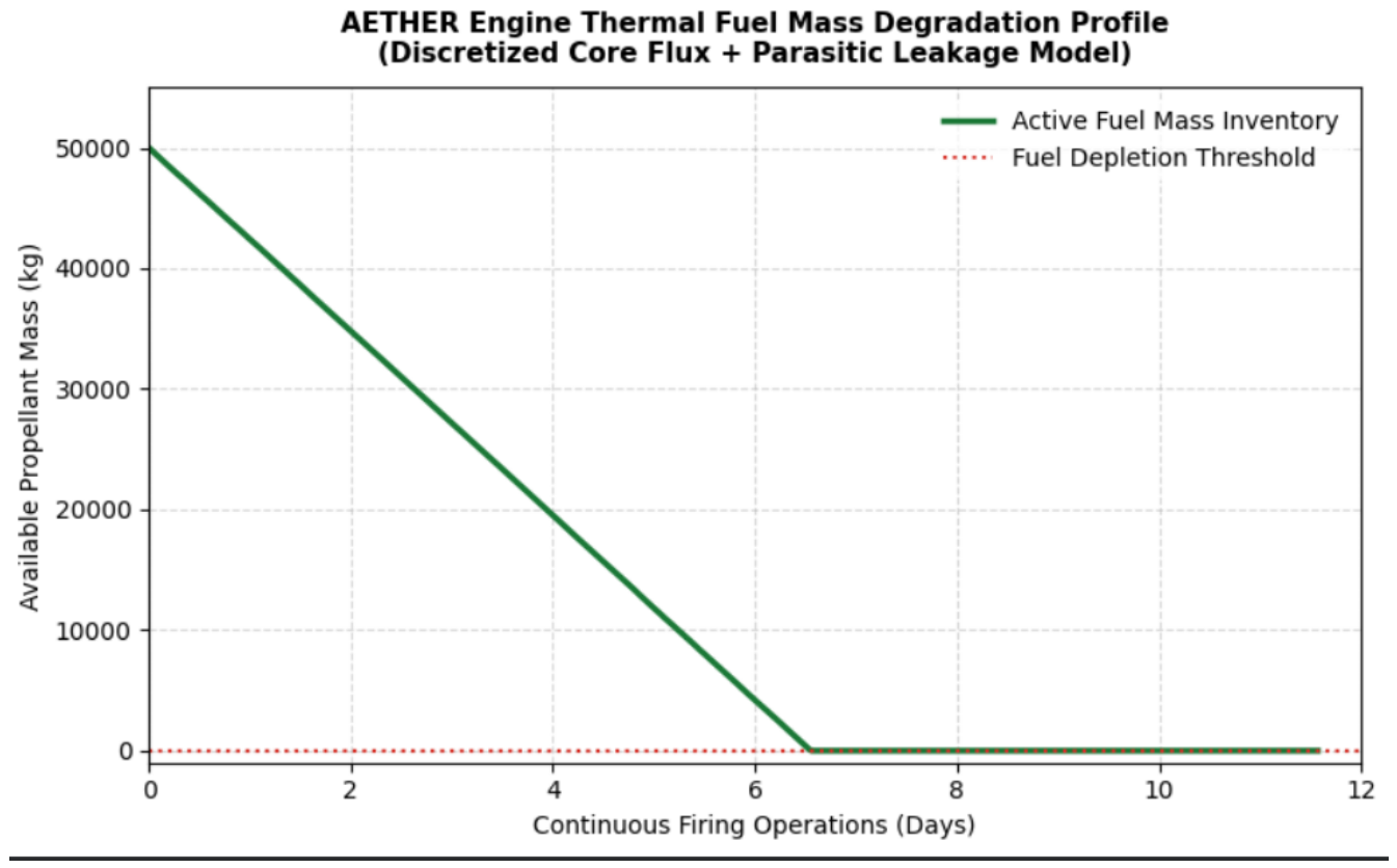
Figure 2.
He−II thermomechanical (fountain) propellant feed profile showing aggregate mass flow rate () versus applied manifold temperature gradient ()[14].
Figure 2.
He−II thermomechanical (fountain) propellant feed profile showing aggregate mass flow rate () versus applied manifold temperature gradient ()[14].
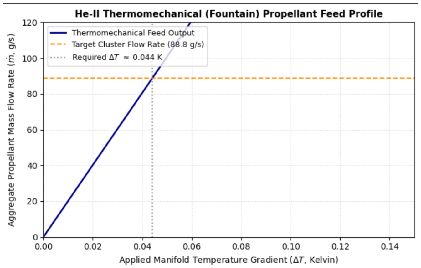
Figure 3.
MHD nozzle boundary confinement profiles showing dynamic magnetic pressure () exceeding required plasma confinement pressure [14].
Figure 3.
MHD nozzle boundary confinement profiles showing dynamic magnetic pressure () exceeding required plasma confinement pressure [14].
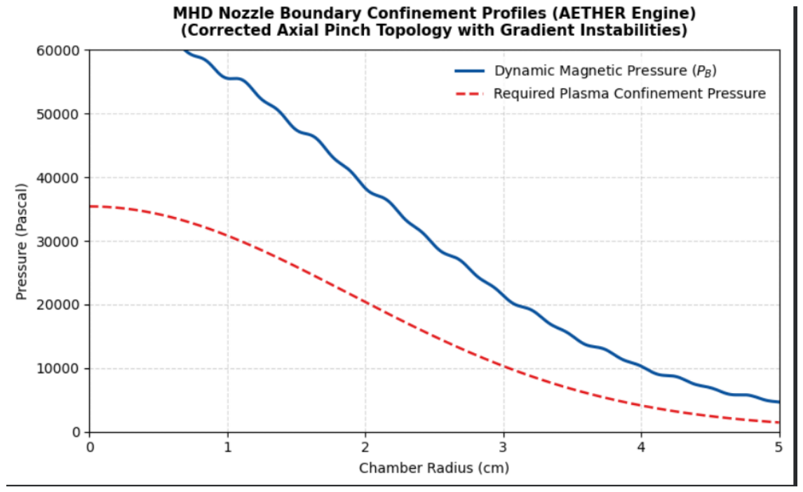

Table 1.
AETHER 10-MW System Baseline Performance Specifications
| Parameter | Per Thruster Module | Full 50-Engine Cluster |
|---|---|---|
| Active Engine Units (N) | 1 | 50 |
| Allocated Thruster Power | 128 kW | 6.4 MW |
| Auxiliary Cryogenic/Systems Power | 72 kW | 3.6 MW |
| Total Input Electrical Power () | 200 kW | 10.0 MW |
| Jet Kinetic Power () | 112.5 kW | 5.625 MW |
| Forward Thrust (F) | 26.64 N | 1332 N |
| Propellant Mass Flow Rate () | 1.78 g/s | 0.0888 kg/s |
| Effective Exhaust Velocity () | 15,000 m/s | 15,000 m/s |
| Specific Impulse () | 1529 s | 1529 s |
| Core Thruster Efficiency () | 87.8% | 87.8% |
| Net System Efficiency () | 56.25% | 56.25% |
| Total Baseline Delta-v () | – | 10,395 m/s |
| Initial Spacecraft Acceleration () | – | 0.0133 m/s2 |
| Continuous Burn Time () | – | 6.50 days |
Disclaimer/Publisher’s Note: The statements, opinions and data contained in all publications are solely those of the individual author(s) and contributor(s) and not of MDPI and/or the editor(s). MDPI and/or the editor(s) disclaim responsibility for any injury to people or property resulting from any ideas, methods, instructions or products referred to in the content. |
© 2026 by the authors. Licensee MDPI, Basel, Switzerland. This article is an open access article distributed under the terms and conditions of the Creative Commons Attribution (CC BY) license (http://creativecommons.org/licenses/by/4.0/).
Copyright: This open access article is published under a Creative Commons CC BY 4.0 license, which permit the free download, distribution, and reuse, provided that the author and preprint are cited in any reuse.