

Submitted:
20 October 2026
Posted:
22 October 2026
You are already at the latest version
Abstract
Longwall top-coal caving (LTCC) can increase recovery from thick seams; however, its performance in overseas mines does not establish transferability to Indian coal measures. This critical integrative review combines peer-reviewed LTCC research, published and technical evidence from the Godavari Valley Coalfield (GVCF), and the statutory and safety evidence needed for controlled implementation in India. The synthesis evaluates top-coal failure and draw, first top-coal caving distance (FTCD), seam and stone-band variability, roof behaviour, in-situ stress, roadway orientation, support response, gas, spontaneous heating, and commissioning controls. Available measurements indicate a broadly north-east–south-west maximum horizontal stress direction in parts of the GVCF, with material local variation; Adriyala experience further indicates that roadway orientation can alter guttering, convergence, and reinforcement demand. Earlier GVCF screening produced divergent cavability and recovery estimates under Chinese and CSIRO-derived approaches, demonstrating model-form uncertainty rather than proving feasibility. The paper therefore proposes a staged evidence-to-decision framework linking regional screening, block qualification, three-dimensional characterisation, calibrated continuum–discontinuum modelling, multi-hazard assessment, an instrumented pilot, and independent review before expansion. LTCC is assessed as conditionally promising for selected GVCF blocks, but not demonstrated at coalfield scale. The principal limitation is the absence of an Indian LTCC production panel for calibration and the heterogeneous accessibility and quality of regional data.
Keywords:
cavability
; first top-coal caving distance
; Godavari Valley Coalfield
; in-situ stress
; longwall top-coal caving
; safety assurance
; thick coal seams
Research Significance
This paper makes three contributions relevant beyond India: it separates regional screening from block-specific proof, treats cavability, roof response, support demand, gas, fire, and draw control as a coupled system, and converts technical predictions into auditable commissioning hold points. The proposed framework is intended to support evidence-based method transfer where direct domestic operating experience is absent.
Introduction
India’s rising energy and industrial requirements, the progressive depletion of shallow deposits amenable to opencast extraction, and the environmental and land constraints associated with increasing stripping ratios strengthen the long-term case for productive underground coal mining. A substantial part of the remaining resource occurs at depths or in geological settings for which underground extraction is the practicable option. Within this resource, thick seams are particularly important but difficult to recover efficiently: seam thickness may exceed the cutting range of conventional equipment, while stone bands, seam splitting, weak coal, strong roof units, and spontaneous-heating liability can sharply narrow the range of workable methods[1,44].
Thick coal seams therefore represent both a strategic resource opportunity and a coupled geotechnical–operational problem. Conventional bord-and-pillar and single-pass longwall systems commonly recover only part of a seam where mining height exceeds the practical cutting range. Multi-slice extraction can improve recovery, but exposes successive slices to redistributed stress, fractured strata, ventilation complexity, and fire risk. Indian trials of multi-slice longwall, blasting gallery, sublevel caving, and hydraulic methods established technical possibilities; however, their uneven continuity also showed that the extraction of coal is not, by itself, evidence of a safe, productive, and scalable mining system. Recovery, ground control, spontaneous heating, equipment reliability, and the quality of geological and operating data must be considered together[1,2,3,4,44].
Against this background, longwall top-coal caving (LTCC) offers a potentially attractive single-lift route for selected thick seams. It combines a conventional longwall cut in the lower part of the seam with controlled drawing of the overlying coal through rear openings in specially designed shields. The upper coal is fractured by mining-induced stress and gravity, sometimes assisted by hydraulic fracturing or pre-splitting, and is loaded on a rear-armoured face conveyor[5,6,7,8,9,10]. This arrangement can extend recovery beyond the shearer cutting height without the repeated development and inter-slice interaction inherent in multi-slice working. However, its apparent simplicity is misleading because cutting, caving, support response, ventilation, and draw control operate as an interdependent system.
International applications demonstrate a broad LTCC operating envelope but do not establish its transferability to Indian coal measures. The boundary between a caveable coal mass and an unstable or poorly recoverable mass is strongly site-dependent. Hard or poorly jointed top coal may bridge above the caving openings, weak or highly fractured coal may cave prematurely, thick strong roof units may overhang and impose high static or dynamic loads, and uncontrolled drawing may increase dilution, residual coal, gas release, and spontaneous heating exposure[11,12,13,14,15,16,17,18]. The first top-coal caving distance (FTCD), fragmentation and flow of top coal, roof breakage sequence, shield–strata interaction, and recognition of the coal–rock interface consequently require block-specific predictions and field validation.
Therefore, the central question is not whether LTCC has worked elsewhere, but what evidence is required to establish whether it can operate safely and productively in a specific block of the Godavari Valley Coalfield (GVCF). The authors’ research programme progressed from an initial Indian feasibility study[43], through a review of thick-seam technologies44 and a synthesis of critical LTCC implementation issues[45], to numerical development and validation of an FTCD-based techno-economic model46. The latter reported an internal rate of return of 30.24% for LTCC compared with 18% for single-pass longwall under stated assumptions, including 70% top-coal recovery, 85% operating performance, 20% cost escalation, and a two-grade reduction in coal quality46. These results identify conditional potential rather than a universal business case: recovery, dilution, caving behaviour, and operating performance must be established through mine-specific investigation and a controlled pilot.
This article integrates the cavability and FTCD findings with GVCF evidence on stress orientation, coal fabric, geological structure, and massive sandstone roofs, and then connects the geotechnical assessment to the safety assurance required for regulatory permission, commissioning, and conditional expansion. It reviews the principal controls and their interfaces with ventilation, gas, fire, water, machinery, and emergency response, and proposes a staged evidence-to-permission framework. Therefore, the contribution is a critical synthesis and implementation pathway—not a claim that LTCC feasibility has already been demonstrated across the GVCF.
Scope and Method
A critical integrative-review design was adopted because the evidence comprises numerical and physical modelling, laboratory studies, mine observations, conference papers, government instruments, and technical reports that cannot be combined through meta-analysis. The source set was developed from the authors’ earlier LTCC studies and updated by backward and forward citation tracing of key cavability, top-coal-flow, roof-control, gas, and stress-orientation papers. Priority was given to peer-reviewed studies that reported geological setting, model assumptions, field measurements, or validation; GVCF technical evidence was retained where it provided otherwise unavailable stress, structural, or roadway-performance data. Generic descriptions without a traceable method or site context were used only for background.
Evidence was coded into four interacting domains: (i) seam properties and discontinuities; (ii) immediate- and main-roof behaviour; (iii) in-situ and mining-induced stress; and (iv) structure and environmental hazards. Findings were compared by mechanism, scale, evidential basis, and transferability to the GVCF, and then translated into a design consequence, verification method, and decision criterion (Figure 1). The regulatory synthesis used the Coal Mines Regulations, 2017, the Occupational Safety, Health and Working Conditions Code, 2020, the draft coal-mine regulations published in 2026, and relevant DGMS guidance. Legal provisions are reported as a dated implementation context, not as a substitute for project-specific legal review or statutory permission.
Figure 1.
Site-specific LTCC feasibility framework integrating seam, roof/floor, stress, and structural evidence with design and risk controls.
Figure 1.
Site-specific LTCC feasibility framework integrating seam, roof/floor, stress, and structural evidence with design and risk controls.
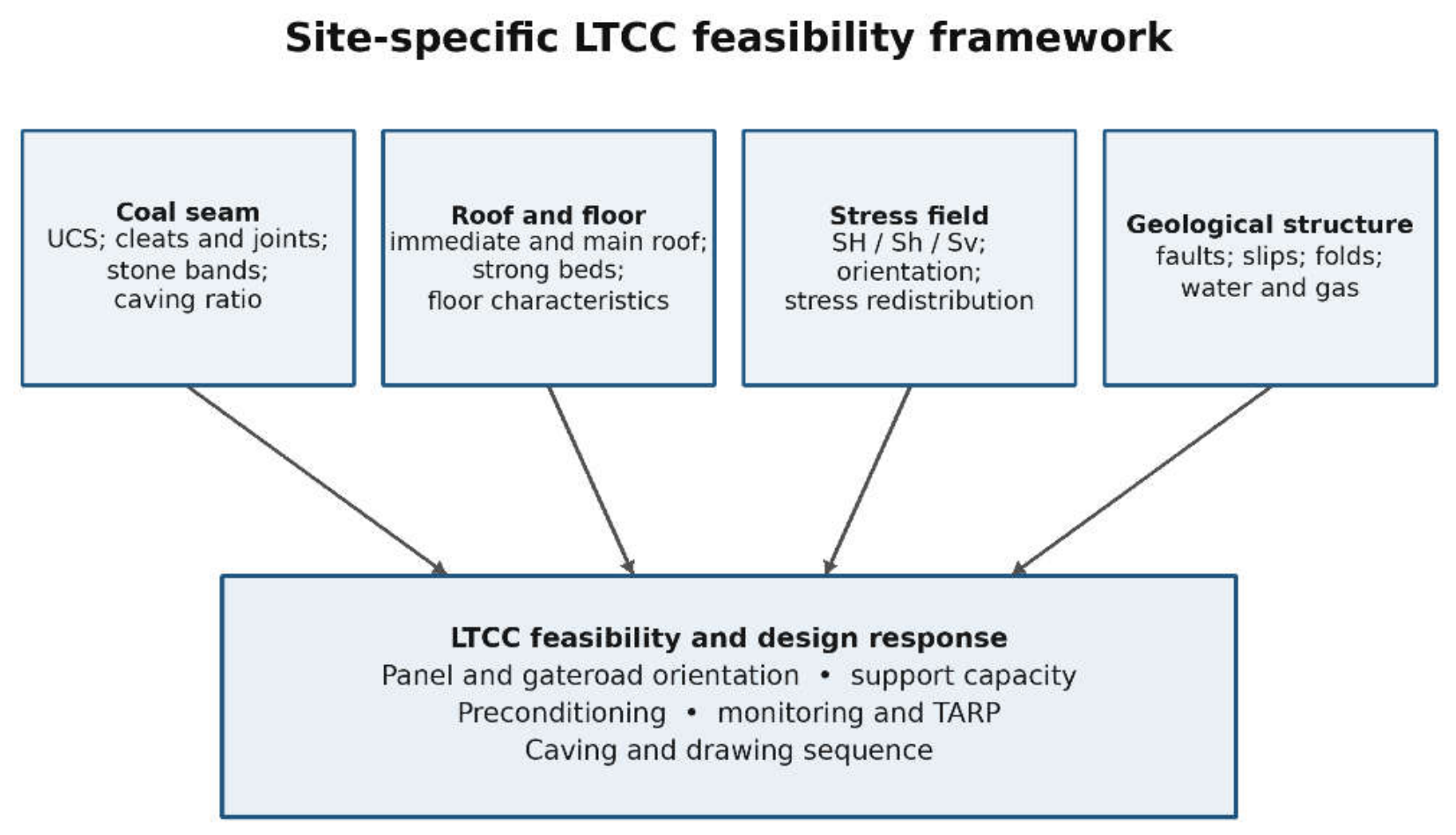

Table 1.
Geotechnical controls, LTCC response, and required verification.
| Domain |
Potential LTCC effect |
Minimum verification |
|---|---|---|
| Coal strength and fabric |
Controls stress-induced failure, fragment size, bridging, and premature caving. |
Oriented core; UCS/tensile strength; cleat/joint spacing, persistence, roughness, and infill. |
| Top-coal thickness and bands |
Controls caving ratio, flow path, residual coal, and dilution. |
3-D seam model; geophysical logs; band strength and thickness; draw modelling. |
| Immediate/main roof |
Delayed caving or large cantilever can increase shield load, convergence, and dynamic risk. |
Bed-by-bed core log, strength, joints, caveability, and support–strata interaction models. |
| Stress field |
Affects roadway damage, top-coal fracture, and abutment loading. |
Hydrofracturing/overcoring, stress mapping, and uncertainty and sensitivity analyses. |
| Faults and slips |
Cause local stress, permeability, and seam geometry changes. |
3-D structural model, probe drilling, and exclusion/crossing plans. |
| Gas, fire and water |
May constrain draw, ventilation, and preconditioning. |
Gas content/permeability; spontaneous-heating indices; hydrogeological model; TARP |
The evidence base was heterogeneous. Some GVCF stress results are obtained from direct hydrofracturing, whereas others are inferred from geotechnical mapping or numerical back analysis. Several mine reports are unpublished and cannot be independently reproduced in the public literature. No Indian LTCC production panels provide direct calibration. Accordingly, the review treats regional trends as screening evidence and does not extrapolate them as panel-design values.
LTCC Mechanism and Geotechnical Requirements
Top-Coal Failure and Draw
Following undercutting, the top coal must pass through progressive damage, fragmentation, and gravity flow. Front abutment stress initiates or extends fractures; shield movement changes confinement; and the caving opening provides a draw point. Recovery depends on the size distribution and mobility of fragments, the caving-to-cutting-height ratio, opening sequence and timing, and the onset of roof-rock dilution[5,6,7,8,9,25,26,27,28]. A high intact uniaxial compressive strength (UCS) does not preclude caving, because bedding, cleats, joints, persistence, and infill determine rock-mass behaviour. Conversely, low UCS does not guarantee controllable flow if weak bands smear, large blocks bridge the opening, or premature caving affects the face.
Therefore, most cavability schemes combine coal strength, discontinuity spacing and orientation, top-coal thickness, roof characteristics, depth or stress, and operational geometry[5,6,17]. For GVCF applications, laboratory UCS and indirect tensile tests should be coupled with oriented-core logging, fracture frequency, roughness, persistence, and infill, and representative bulk-density and moisture measurements. A single borehole average is inadequate where seams split, merge, or contain stone bands.
Figure 4.
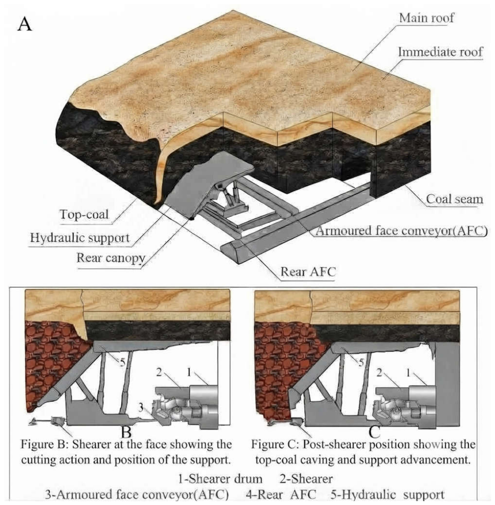
Schematic mechanism of longwall top coal caving (LTCC), showing lower-seam cutting and controlled drawing of fragmented top coal.
Figure 4.
Schematic mechanism of longwall top coal caving (LTCC), showing lower-seam cutting and controlled drawing of fragmented top coal.
Progressive Failure, Fragmentation and Drawing
Top-coal failure is progressive rather than instantaneous. Front abutment loading first promotes closure, slip, compressive yielding, and shear damage along existing discontinuities. After the face passes, undercutting and shield advance reduce confinement, allowing dilation, bedding separation, tensile cracking, block rotation, and gravity-driven movement towards the rear caving opening. Numerical studies place the peak front abutment load only a few metres ahead of some investigated faces, but the broader disturbed zone varies substantially with depth, material model, seam geometry and boundary conditions; these distances are therefore case outputs, not transferable design constants.[19,26,51,52]
Fracture generation alone is insufficient: fragments must pass through the caving window without stable arching, delayed release, or unacceptable roof-rock dilution. The draw sequence and opening duration govern the evolving boundary between moving and stationary coal or waste. Hard stone bands may behave as short beams, interrupt the failure zone and produce coarse blocks; their thickness, position, continuity and strength should be represented explicitly rather than averaged into a single seam property.[8,53,54]
Where natural mining-induced damage is inadequate, hydraulic fracturing, water infusion, or controlled pre-splitting may be considered. Treatment should target a distributed fracture network and must be verified by borehole imaging, injection records, and observed caving response. Its possible effects on methane and water pathways, roof stability, shield loading and roadway integrity require assessment before use.[11,12,52]
Caving Ratio and Seam Variability
The ratio of top-coal thickness to cutting height influences both fragmentation and the space available for movement. Ratios of approximately [1,2,3] are common in many applications, although higher values occur in ultra-thick seams5. Increasing the ratio can raise the recoverable inventory per metre of face advance, but it also lengthens the flow path and may increase residual coal and dilution. Seam rolls, splits, and stone bands should therefore be modelled in three dimensions. Panel-scale production forecasts should report clean-coal recovery, dilution, and residual-coal distribution separately rather than quoting a single extraction percentage.
Immediate and Main Roof
An effective LTCC roof must perform two apparently conflicting functions. The immediate roof should cave without excessive delay and help transfer the load to the top coal, whereas the main roof should not form a large, uncontrolled cantilever behind the supports. Thick strong sandstone or conglomerate beds can increase the weighting interval, shield loading, face convergence, spalling, and air-blast potential[29,30,31,32,33]. Therefore, bed thickness, strength, and distance above the seam are as important as a generic lithological label.
Where a hard roof or hard top coal is identified, preconditioning may include hydraulic fracturing, water infusion, or carefully designed blasting[11,12,32]. Such measures require proof of fracture extent, control of interaction with aquifers and gas pathways, and confirmation that induced fractures do not compromise gate-road stability. Support selection must be based on dynamic as well as static load demand and should be checked through support–strata interaction modelling[34].
Stress Field and Orientation
Excavation redistributes the pre-mining stress field and creates front, side, and rear abutment zones. Maximum horizontal stress can concentrate across roadways oriented unfavourably to it, causing cutter roof, guttering, bed separation, and asymmetric deformation. Roadways driven near-parallel to the maximum horizontal stress commonly experience lower concentration at the heading, although local structure, anisotropy, and mining sequence can modify this relation[21,22,35,36]. LTCC adds a second requirement: panel orientation must also support controlled coal fracture and roof caving. Therefore, orientation is an optimisation problem, not a universal rule (Figure 2).
Godavari Valley Coalfield: Geological and Geotechnical Setting
Basin Architecture and Coal Measures
The Pranhita–Godavari Gondwana basin trends broadly north-northwest to south-southeast and extend for about 350 km through Telangana and Andhra Pradesh; its northern continuation is commonly termed the Wardha Valley Coalfield. Gondwana strata rest unconformably on Precambrian rocks. The principal Lower Gondwana units are the Talchir, Barakar, Barren Measures, and Kamthi formations. Coal-bearing Barakar and lower Kamthi successions contain interbedded sandstone, shale, clay, and coal, with marked lateral changes in bed thickness and seam splitting[37,38,39,40]. These variations matter directly to LTCC because a thick sandstone close to the seam can govern first and periodic weighting, while clay or shale bands may affect both caving and dilution.
Cleats, Joints, Faults and Slips
Regional mapping indicates that face cleats commonly trend NE–SW and butt cleats NW–SE, with local departures. Equivalent seams may show broadly comparable cleat patterns, but local verification remains necessary[41]. Cleat orientation affects cutting, spalling, and fragment geometry. A face parallel to a dominant cleat may promote large slab release, while a face at another angle may produce smaller fragments but different roof-break behaviour. The optimum cannot be inferred from coal cleats alone because roof joints and the stress field must be considered jointly.
Roof-joint density and orientation influence roof stability and the direction in which a main-roof break propagates. Faults and slip planes introduce abrupt changes in stress, permeability, seam elevation, and roof competence. At GDK-10A, reported slip trend was approximately N85°W, with downthrow generally towards N25°E and dips of 60–70°. Such observations are valuable for screening, but panel design requires three-dimensional structural interpretation, uncertainty envelopes around fault position, and crossing or exclusion strategy.
In-Situ Stress Evidence
Direct and indirect measurements across the GVCF show a broadly NE–SW maximum horizontal stress and NW–SE minimum horizontal stress, but the azimuth and magnitude vary between sites (Table 2). Hydrofracturing at the Adriyala block produced 17 successful tests over depths of 77–522 m. The reported mean fracture azimuth was N24°E ± 14°. Stress–depth relations were Sh = 2.05 + 0.0092(z – 77), SH = 3.13 + 0.0142(z – 77), and Sv = 0.0216z, with stress in MPa and depth z in metres23. These relations are site-derived regressions, not coalfield-wide design equations.
Geotechnical mapping at VK-7, Goleti-1, GDK-11A, GDK-10A, and Padmavathi Khani similarly indicates stress-related roadway anisotropy. The practical significance is illustrated by the Adriyala gate-road development: cut-throughs initially oriented approximately 60–70° to the major horizontal stress experienced severe guttering and convergence; after reorientation to approximately 15–20°, conditions improved. Additional cable bolting and increased support density were used where operational requirements forced an unfavourable orientation. This is valuable observational evidence of orientation sensitivity, although it was not a controlled LTCC trial.
Integrated LTCC Feasibility Assessment for GVCF
Regional Screening Versus Block Qualification
The available evidence supports regional screening but not a blanket finding that the GVCF is suitable for LTCC. Thick seams and established longwall infrastructure are positive indicators. Potential constraints include massive sandstone roofs, seam splitting, stone bands, stress anisotropy, structural disturbance, methane, spontaneous heating, and water-bearing strata. A block should proceed to detailed assessment only where seam continuity, top-coal thickness, and infrastructure provide a plausible production case and no fatal geological or environmental constraint is evident.
Historical GVCF Cavability Screening
An earlier first-pass assessment examined LTCC for the thick III seam in the Ramagundam–Adriyala area, reported at approximately 8–10 m thickness, 8–10° dip, and 300–400 m depth. Under the assumed inputs, the Chinese cavability index indicated “good” to “very good” conditions and about 70–80% recovery, whereas a CSIRO relationship derived from COSFLOW parametric modelling indicated “moderate to good” cavability and about 56–67% recovery. This divergence is evidence of model-form uncertainty. Neither approach was calibrated against an Indian LTCC panel, and both are sensitive to coal strength, fracture characterization, top-coal thickness, stone bands and depth.[18,43]
Therefore, the historical indices are retained only as screening tools. They do not resolve discontinuity persistence and orientation, three-dimensional stone-band geometry, stress direction, FTCD, fragment-size distribution, or dilution. Contemporary qualification should report sensitivity ranges and compare empirical classifications with calibrated continuum–discontinuum and physical models rather than presenting one deterministic recovery value.[5,6,7,18,43]
Minimum Geotechnical Characterization
A qualified block requires oriented coring through the seam, floor, and sufficient overburden to capture the immediate and main roof; geophysical logging; structural interpretation; laboratory and rock-mass properties; hydrofracturing or overcoring for stress magnitude and orientation; permeability and gas measurements; and baseline microseismic and convergence observations where access exists. Borehole spacing should respond to geological variability rather than a fixed regional rule. The data should populate a geotechnical model that records both the best estimate and uncertainty.
Modelling and Design Verification
Numerical analysis should test extraction height, caving ratio, panel width, face orientation, gate-road position, support capacity, roof break, and multi-seam interaction. Continuum models are useful for stress and roadway response, whereas discontinuum or bonded-particle approaches are better suited to fracture and granular flow[6,7,26,27]. Physical modelling can provide an independent check on draw and dilution. Model calibration must use GVCF observations from development or conventional longwall panels; importing material parameters from foreign LTCC mines without sensitivity analysis would create false precision.
Pilot-Panel and Monitoring Logic
If modelling supports conditional feasibility, a pilot should be designed as an instrumented experiment rather than an early production commitment. It should include shield-leg pressure, convergence, extensometry, microseismic monitoring, gas and temperature trends, airflow and pressure, coal-quality sampling, and draw-point records. Trigger-action-response plans should define thresholds for delayed caving, abnormal shield loading, convergence, gas, carbon monoxide, spontaneous-heating indicators, water, and seismic events. The pilot should contain explicit stopping rules and an independent technical review before replication.
Safety and Regulatory Pathway for Indian Implementation
Permission and Legal-Status Boundary
LTCC cannot be initiated merely because a technical study indicates favourable economics. The Coal Mines Regulations, 2017 contain the established permission framework for extraction by a system other than bord-and-pillar, while the Occupational Safety, Health, and Working Conditions Code, 2020 took effect on 21 November 2025 and draft subordinate coal-mine regulations were published in 2026. Because saving, transition, and subordinate-law arrangements must be applied to the facts and date of a project, any submission should include a dated legal-status note and obtain all permissions required by the competent authority. The framework proposed here is technical guidance, not legal advice or regulatory approval.
Mine-Specific Permission Dossier
A credible permission dossier should connect every major uncertainty to evidence and a control owner. At minimum, it should contain the three-dimensional geological model; oriented discontinuity and stress data; cavability and FTCD assessment; support-rating and support–strata interaction studies; subsidence and multi-seam analysis; ventilation-network and peak-gas-emission models; spontaneous-heating and inertisation design; water-hazard assessment; equipment approval and functional-safety documentation; emergency arrangements; and a mine-specific risk assessment. The strata control and monitoring plan (SCAMP), support plan, operating code, trigger-action-response plans (TARPs), and training and management-of-change process should use one reconciled set of limits. Conflicting thresholds across studies or procedures are themselves an unsafe condition.
Commissioning as a Controlled Scientific Trial
The first panel segment should be declared a commissioning zone. Cutting may begin only after baseline measurements and proof testing of ventilation, communications, gas monitors, trips, support-pressure monitoring, emergency stops, conveyors, sprays, and data logging. Top-coal drawing should commence at a formal hold point after observed top-coal damage and roof response are reviewed against the predicted FTCD. First caving and main-roof weighting require enhanced instrumentation, restricted personnel exposure, remote observation where practicable, and explicit withdrawal criteria. A predicted FTCD should be treated as a hypothesis to be validated, not as an instruction to open caving windows automatically.
Integrated Critical Controls
LTCC must be operated as a coupled strata–gas–fire–dust–machinery system. A support or draw decision can change the goaf permeability, methane release, oxygen ingress, residual-coal distribution, and dust. The principal critical controls are summarised in Table 4. Powered supports require verified capacity, setting pressure, yield behaviour, alignment, and limits on adjacent unavailable shields. The draw code should define the opening sequence, duration, separation from the shearer, and dilution stop criteria. Entry beneath an open caving window or behind the support canopy should be prohibited. Large-block hang-ups require an isolated, engineered remote procedure; manual barring or blasting from the line of release is unacceptable.
Ventilation should be designed for credible peak emission and goaf leakage rather than average production. Current DGMS guidance specifies minimum air-quantity considerations for continuous miners and longwall panels; however, larger statutory, permission, and scientific-study values should govern50. Fixed and portable monitoring should cover the tailgate/face return, immediate panel return, and other high-risk locations. Alarm, stop, trip, withdrawal, and restart values must be derived from the operative law, equipment approvals, and permission; illustrative values in a model bye-law must never be copied into an operating document without reconciliation.
Residual top coal creates a persistent spontaneous-heating concern. Recovery and dilution should be reconciled from cut tonnes, drawn tonnes, survey, and seam geometry. Monitoring should use baseline-corrected trends in CO, CO2, O2, and CH4, supplemented by indices appropriate to the seam. Nitrogen inertisation capacity, injection locations, pressure balancing, stoppage rules, and emergency sealing should be established before production. A fire TARP should respond to trends and rates of change rather than relying on a single universal CO concentration.
Hold Points, Management of Change and Expansion
The pathway in Figure 3 contains decision gates at which the project may stop, acquire more evidence, or redesign. Red triggers—such as uncontrolled caving, excessive shield loading or closure, ventilation below minimum, methane or fire escalation, abnormal water inflow, failed critical monitoring, unavailable escapeway, or loss of communications—require suspension and defined restart authority. Changes to cutting height, caving ratio, panel geometry, draw sequence, support set points, ventilation, drainage, inertisation, software, or sensor thresholds require formal management-of-change review and, where they depart from permission, prior regulatory acceptance. Expansion beyond the pilot should depend on an independent review of recovery, dilution, support response, gas and fire behaviour, incidents, model calibration, and economic sensitivity—not on output alone.
Discussion
The strongest conclusion from the GVCF evidence is that orientation and caving cannot be treated independently. Aligning gate roads favourably to SH can reduce development damage, but face orientation also influences coal spalling, roof-joint activation, stress transfer, and panel sequence. A multi-criteria orientation study should therefore compare alternatives for development stability, retreat loading, structural crossing, ventilation, drainage, and surface constraints. The result may be a compromise supported by higher reinforcement in localised unfavourable headings.
Second, the massive sandstone problem must be quantified rather than described. “Hard roof” should be converted into bed thickness, UCS, tensile strength, modulus, joint spacing, distance from seam, and likely span at break. The risk is not limited to delayed caving; sudden failure can produce dynamic shield loading, wind blast, and rapid gas displacement. Preconditioning should be evaluated only after its effect on water and gas pathways has been modelled and monitored.
Third, a cavability rating is a screening tool, not a design approval. Published classification systems assign different weights to coal UCS, discontinuities, thickness, roof, and stress[5,17]. Their transferability to Indian coal measures is uncertain. A GVCF-specific criterion should be calibrated using laboratory fragmentation, instrumented longwall roof response, and ultimately, pilot LTCC observations. Until such calibration exists, classifications should be reported with sensitivity ranges and uncertainty levels.
Finally, geotechnical feasibility is necessary but not sufficient. LTCC leaves residual coal in a caved, ventilated environment and can increase gas release and spontaneous-heating exposure. Draw control also determines dilution and coal quality. The final investment and statutory decision must integrate geotechnical, ventilation, gas, fire, water, equipment, emergency-response, economic, and environmental studies. Table 3 summarises the evidence-to-decision pathway.
Indian sublevel-caving experience at East Katras offers a caution relevant to LTCC transfer: demonstrating that thick coal can be caved is not equivalent to demonstrating sustained system performance. Roof behaviour, recovery discipline, residual-coal management, equipment reliability, and fire control must remain stable over the operating life of a panel. Accordingly, the proposed pilot is evaluated against coupled safety and production indicators rather than output alone.[43,44]
The integrated framework also clarifies the novelty of the present contribution. Earlier work established the Indian LTCC problem, reviewed alternative thick-seam methods, identified critical LTCC aspects, and modelled FTCD-linked recovery and economics[43,44,45,46]. The present synthesis advances this programme by defining how these scientific results should be converted into a permission dossier, validated at commissioning hold points, controlled through multi-hazard TARPs, and reviewed before expansion. This separation between prediction, permission, and validation is essential: a technically plausible model is not equivalent to an approved operating system.
Limitations and Research Priorities
This review is limited by heterogeneous data, incomplete public access to mine reports, differences in measurement methods, and the absence of an Indian LTCC trial. The proposed regulatory pathway is interpretive and must be reconciled with the law and permission conditions in force at the time of application. Some regional statements are based on a small number of sites and should not be used as design values. Future work should establish a digital GVCF geotechnical database with traceable borehole, laboratory, structural, and stress records; compare cavability indices against discontinuum modelling; quantify the mechanical effect of stone bands; develop hard-roof preconditioning criteria; integrate methane and spontaneous-heating models with draw strategy; and test automated coal–rock interface recognition under Indian conditions[42]. A monitored pilot should publish both successful and adverse observations so that later designs are evidence-based.
Conclusions
LTCC is conditionally promising for selected thick-seam blocks in the GVCF, but current evidence supports screening and pilot design—not coalfield-wide adoption. The absence of an Indian LTCC production panel is a decisive calibration gap.
Top-coal recovery depends on a progressive shear-to-tensile damage process followed by controllable granular flow. Coal strength alone is an inadequate cavability descriptor; discontinuity persistence and orientation, stone bands, caving ratio, stress, roof behaviour, and draw sequence must be evaluated together.
The broadly north-east–south-west maximum horizontal stress observed at several GVCF sites is useful regional evidence, but local measurements and structural interpretation must govern the panel and roadway orientation. Site-derived stress–depth equations and reported peak-abutment distances should not be generalised as design constants for underground coal mines.
A defensible implementation pathway comprises regional screening, block qualification, three-dimensional geological and geotechnical characterisation, calibrated multi-method modelling, support and multi-hazard verification, and an instrumented commissioning zone controlled by TARPs and explicit stop–review–restart authority.
Regulatory permission should be supported by one reconciled evidence chain linking the geotechnical model, SCAMP, support plan, ventilation and gas studies, spontaneous-heating and inertisation arrangements, water assessment, equipment approvals, emergency plan, and training. Expansion should follow only after an independent review confirms acceptable safety performance, recovery, and dilution, and after the models are recalibrated against commissioning observations.
Supplementary Materials
The following supporting information can be downloaded at the website of this paper posted on Preprints.org.
Author Contributions
N.B.: conceptualisation, evidence synthesis, field-context interpretation, and original draft. N.B.: geotechnical interpretation, critical review, and manuscript refinement. Both authors approved the manuscript.
Acknowledgments
The authors acknowledge the organisations and researchers whose published studies and technical reports informed this review. This analysis was part of the doctoral work of the first author.
Conflicts of Interest
The author declares no conflict of interest.
References
- Kumar, R.; Singh, A. K.; Mishra, A. K.; Singh, R. Underground mining of thick coal seams. Int. J. Min. Sci. Technol. 2015, 25, 885–896. [Google Scholar] [CrossRef]
- Sinha, P. K.; Verma, R. K.; Jain, D. K. Research and development efforts in thick seam mining: present and future scenario. In Proceedings of the International Symposium on Thick Seam Mining; Dhanbad, Singh, T. N., Dhar, B. B., Eds.; CMRI; pp. 471–492.
- Das, T. K.; Singh, T. N. Hydraulic mining at Gopalichak Colliery of Jharia Coalfield. J. Mines Met. Fuels 1995, 43, 7–16. [Google Scholar]
- Dash, A. K.; Bhattacharjee, R. M. Role of convergence behaviour for superior recovery of thick coal seams in underground mines by blasting gallery. J. Mines Met. Fuels 2016, 64, 109–116. [Google Scholar]
- Le, T. D.; Mitra, R.; Oh, J.; Hebblewhite, B. A review of cavability evaluation in longwall top coal caving. Int. J. Min. Sci. Technol. 2017, 27, 907–915. [Google Scholar] [CrossRef]
- Le, T. D.; Zhang, C.; Oh, J.; Mitra, R.; Hebblewhite, B. A new cavability assessment for longwall top coal caving from discontinuum numerical analysis. Int. J. Rock Mech. Min. Sci. 2019, 115, 11–20. [Google Scholar] [CrossRef]
- Le, T. D.; Oh, J.; Hebblewhite, B.; Zhang, C.; Mitra, R. A discontinuum modelling approach for investigation of longwall top coal caving mechanisms. Int. J. Rock Mech. Min. Sci. 2018, 106, 84–95. [Google Scholar] [CrossRef]
- Wang, J.; Yang, S.; Li, Y.; Wei, L.; Liu, H. Caving mechanisms of loose top coal in longwall top-coal caving mining. Int. J. Rock Mech. Min. Sci. 2014, 71, 160–170. [Google Scholar] [CrossRef]
- Wang, J.; Zhang, J.; Song, Z.; Li, Z. Three-dimensional experimental study of loose top-coal drawing law for longwall top-coal caving. J. Rock Mech. Geotech. Eng. 2015, 7, 318–326. [Google Scholar] [CrossRef]
- Wang, J.; Yu, B.; Kang, H.; et al. Key technologies and equipment for a fully mechanized top-coal caving operation with a large mining height at ultra-thick coal seams. Int. J. Coal Sci. Technol. 2015, 2, 97–161. [Google Scholar] [CrossRef]
- Huang, B.; Wang, Y.; Cao, S. Cavability control by hydraulic fracturing for top coal caving in hard thick coal seams. Int. J. Rock Mech. Min. Sci. 2015, 74, 45–57. [Google Scholar] [CrossRef]
- Huang, B.; Cheng, Q.; Zhao, X.; Kang, C. Hydraulic fracturing of hard top coal and roof for controlling gas during the initial mining stages in LTCC: a case study. J. Geophys. Eng. 2018, 15, 2492–2506. [Google Scholar] [CrossRef]
- Bai, Q.; Tu, S.; Wang, F.; Zhang, C. Field and numerical investigations of gateroad system failure induced by hard roofs in a LTCC face. Int. J. Coal Geol. 2017, 173, 176–199. [Google Scholar] [CrossRef]
- Si, G.; Jamnikar, S.; Lazar, J.; et al. Monitoring and modelling of gas dynamics in multi-level LTCC of ultra-thick seams, Part I. Int. J. Coal Geol. 2015, 144–145, 98–110. [Google Scholar] [CrossRef]
- Si, G.; Shi, J.-Q.; Durucan, S.; et al. Monitoring and modelling of gas dynamics in multi-level LTCC of ultra-thick seams, Part II. Int. J. Coal Geol. 2015, 144–145, 58–70. [Google Scholar] [CrossRef]
- Bai, Q.; Tu, S. A general review on longwall mining-induced fractures in near-face regions. Geofluids 2019, 2019, 3089292. [Google Scholar] [CrossRef]
- Vakili, A.; Hebblewhite, B. K. A new cavability assessment criterion for longwall top coal caving. Int. J. Rock Mech. Min. Sci. 2010, 47, 1317–1329. [Google Scholar] [CrossRef]
- Khanal, M.; Adhikary, D.; Balusu, R. Prefeasibility study—geotechnical studies for introducing longwall top coal caving in Indian mines. J. Min. Sci. 2015, 51, 719–732. [Google Scholar] [CrossRef]
- Yasitli, N. E.; Unver, B. 3D numerical modeling of longwall mining with top-coal caving. Int. J. Rock Mech. Min. Sci. 2005, 42, 219–235. [Google Scholar] [CrossRef]
- Unver, B.; Yasitli, N. E. Modelling of strata movement with special reference to caving mechanism in thick-seam coal mining. Int. J. Coal Geol. 2006, 66, 227–252. [Google Scholar] [CrossRef]
- Kushwaha, A.; Singh, S. K.; Muralimohan, G.; Sheorey, P. R. Effect of in-situ horizontal stresses on roadway stability. J. Mines Met. Fuels 2003, 51, 134–142. [Google Scholar]
- Mucho, T. P.; Mark, C. Determining horizontal stress direction using the stress mapping technique. In Proceedings of the 13th Conference on Ground Control in Mining, West Virginia University, 1994; pp. 277–289. [Google Scholar]
- MeSy India Pvt Ltd. Adriyala Longwall Block 202.00: Stress and Permeability Testing in Boreholes, Test Site 1205 at SCCL near Ramagundam, India. Technical Report SCCL01/07. 2008; pp. 1–57.
- Rao, A. M.; Sharma, D. N. Stress orientation in the Godavari Gondwana Graben, India. J. Rock Mech. Tunn. Technol. 2014, 20, 109–119. [Google Scholar]
- Zhang, N.; Liu, C.; Pei, M. Effects of caving–mining ratio on coal and gangue flows and cyclically caved coal in super-thick seams. Int. J. Min. Sci. Technol. 2015, 25, 145–150. [Google Scholar] [CrossRef]
- Xie, H.; Chen, Z.; Wang, J. Three-dimensional numerical analysis of deformation and failure during top coal caving. Int. J. Rock Mech. Min. Sci. 1999, 36, 651–658. [Google Scholar] [CrossRef]
- Potyondy, D. O.; Cundall, P. A. A bonded-particle model for rock. Int. J. Rock Mech. Min. Sci. 2004, 41, 1329–1364. [Google Scholar] [CrossRef]
- Zhang, Q.; Yue, J.; Liu, C.; Feng, C.; Li, H. Study of automated top-coal caving in extra-thick seams using the continuum–discontinuum element method. Int. J. Rock Mech. Min. Sci. 2019, 122, 104033. [Google Scholar] [CrossRef]
- Trueman, R.; Lyman, G.; Cocker, A. Longwall roof control through a fundamental understanding of shield–strata interaction. Int. J. Rock Mech. Min. Sci. 2009, 46, 371–380. [Google Scholar] [CrossRef]
- Jeffrey, R. G.; Mills, K. W. Hydraulic fracturing applied to inducing longwall coal-mine goaf falls. In Proceedings of the 4th North American Rock Mechanics Symposium, Seattle, 2000; pp. 423–430. [Google Scholar]
- Mills, K. W.; Jeffrey, R. G.; Hayes, P. Applications of hydraulic fracturing to control caving events in coal mines—the Moonee experience. In Proceedings of the 3rd Underground Coal Operators’ Conference, Wollongong, 2003. [Google Scholar]
- Yu, B.; Zhao, J.; Xiao, H. Case study on overburden fracturing during LTCC using microseismic monitoring. Rock Mech. Rock Eng. 2017, 50, 507–511. [Google Scholar] [CrossRef]
- Prusek, S.; Rajwa, S.; Wrana, A.; Krzemień, A. Assessment of roof fall risk in longwall coal mines. Int. J. Min. Reclam. Environ. 2017, 31, 558–574. [Google Scholar] [CrossRef]
- Verma, A. K.; Deb, D. Numerical analysis of an interaction between hydraulic-powered support and surrounding rock strata. Int. J. Geomech. 2013, 13, 181–192. [Google Scholar] [CrossRef]
- Fabjanczyk, M. W. Directional drivage influences and application of mechanistic mapping techniques. In Geology in Longwall Mining; McNally, G. H., Ward, C. R., Eds.; Sydney, 1992; p. 137. [Google Scholar]
- Sharma, D. N.; Shivanarayana, U.; Pankaj, K. Stress mapping in preferred orientation of galleries in underground coal mines. J. Rock Mech. Tunn. Technol. 2006, 12, 147–155. [Google Scholar]
- Raja Rao, C. S. Coalfields of India, Vol. II: Coal Resources of Tamil Nadu, Andhra Pradesh, Orissa and Maharashtra. In Bulletin Series A; Geological Survey of India, 1982. [Google Scholar]
- Ramanamurty, B. V.; Parthasarathy, E. V. R. On the evolution of the Godavari Gondwana Graben based on LANDSAT imagery interpretation. J. Geol. Soc. India 1988, 32, 417–425. [Google Scholar] [CrossRef]
- Bhagavan, S. V. B. K.; Raghu, V.; Rao, N. A. Tectonic and lineament mapping of Godavari Valley Coalfields using remote sensing. Int. Arch. Photogramm. Remote Sens. Spat. Inf. Sci. 2002, XXXIV, 477–481. [Google Scholar]
- Shanmukha Rao, M.; Uday Bhaskar, G. Geological and geotechnical characterisation using geophysical logs—an example from Adriyala Longwall Project. ASEG Ext. Abstr. 2015, 1, 1–5. [Google Scholar] [CrossRef]
- Sharma, D. N. A study of coal cleat pattern in Godavari Valley Coalfield. Indian J. Geol. 1996, 68, 185–192. [Google Scholar]
- Zhang, G.; Wang, Z.; Zhao, L. Recognition of rock–coal interface in top coal caving through tail-beam vibrations using stacked sparse autoencoders. J. Vibroeng. 2016, 18, 4261–4275. [Google Scholar] [CrossRef]
- Balasubrahmanyam, N.; Budi, G. A study into the feasibility of application of longwall top coal caving (LTCC) method in Indian geo-mining conditions. In Proceedings of the International Conference on Deep Excavation, Energy Resources and Production (DEEP16), IIT Kharagpur, India, 24–26 January 2017; Paper No. 109. [Google Scholar]
- Balasubrahmanyam, N.; Budi, G. A critical review of Indian underground thick coal seam mining technologies and future prospects. Int. Res. J. Eng. Technol. 2021, 8, 1748–1763. [Google Scholar]
- Balasubrahmanyam, N.; Budi, G. Critical aspects of longwall top coal caving method for application in Indian geomining conditions. In Proceedings of Geotechnical Challenges in Mining, Tunneling and Underground Infrastructures; Verma, A. K., et al., Eds.; Springer: Singapore, 2022; pp. 77–96. [Google Scholar] [CrossRef]
- Balasubrahmanyam, N.; Budi, G. Techno-economic feasibility of the longwall top coal caving method based on the FTCD index: a parametric case study in India. Energies 2021, 14, 6115. [Google Scholar] [CrossRef]
- Government of India, Coal Mines Regulations; Gazette of India, Ministry of Labour and Employment: New Delhi, 2017.
- Government of India, Occupational Safety, Health and Working Conditions Code, 2020 (37 of 2020), brought into force with effect from. 21 November 2025.
- Ministry of Labour and Employment, Draft Occupational Safety, Health and Working Conditions (Coal Mines) Regulations, 2026, G.S.R. 67(E), Gazette of India. Gazette of India, 28 January 2026.
- Directorate General of Mines Safety. Guidelines on minimum air quantity required for continuous-miner and longwall panels in coal mines. DGMS (Tech.)(S&T) Circ. 02 2025 2025. [Google Scholar]
- Alehossein, H.; Poulsen, B. A. Stress analysis of longwall top coal caving. Int. J. Rock Mech. Min. Sci. 2010, 47, 30–41. [Google Scholar] [CrossRef]
- Wang, Z.; Tang, Y.; Gong, H. Longwall top-coal caving mechanism and cavability optimization with hydraulic fracturing. Energies 2021, 14, 4832. [Google Scholar] [CrossRef]
- Wang, J.; Yang, S.; Wei, W.; et al. Drawing mechanisms for top coal in longwall top coal caving: a review of two decades of literature. Int. J. Coal Sci. Technol. 2021, 8, 1171–1196. [Google Scholar] [CrossRef]
- Bai, Q.; Tu, S.; Wang, F.; Zhang, C. Characterizing top-coal cavability with hard stone bands: insights from laboratory physical modelling. Rock Mech. Rock Eng. 2019, 52, 1505–1521. [Google Scholar] [CrossRef]
Figure 2.
Conceptual influence of roadway orientation on major horizontal stress. This is a design screening principle, and the local structure and mining sequence may modify the response.
Figure 2.
Conceptual influence of roadway orientation on major horizontal stress. This is a design screening principle, and the local structure and mining sequence may modify the response.
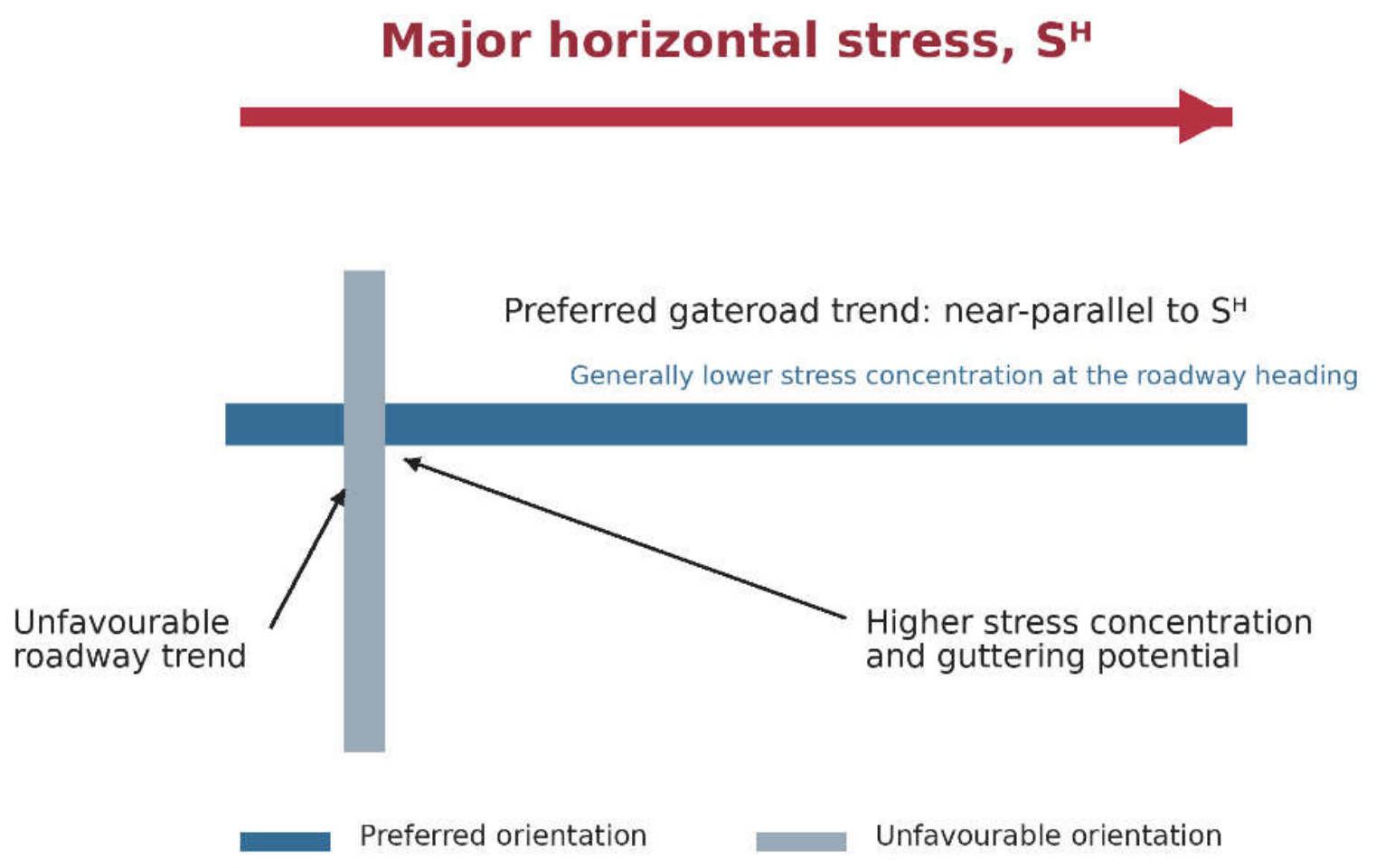
Figure 3.
Proposed evidence-to-permission pathway for the controlled introduction of LTCC in India. Each stage is a hold point rather than an automatic progression.
Figure 3.
Proposed evidence-to-permission pathway for the controlled introduction of LTCC in India. Each stage is a hold point rather than an automatic progression.
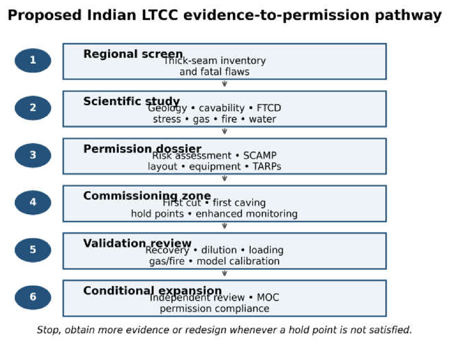
Table 2.
Representative stress-orientation evidence reported from the GVCF.
| Site/seam |
Depth (m) |
SH direction |
Sh direction |
Magnitude (MPa) |
Evidence |
|---|---|---|---|---|---|
| VK-7, Queen |
250 |
N55°E |
N35°W |
Not reported |
Geotechnical mapping |
| Padmavathi Khani, King |
380 |
N45°E |
N45°W |
SH 7.15; Sh 3.68 |
Mapping and numerical estimation |
| Goleti-1, Middle |
230 |
N5°E |
N85°W |
Not reported |
Geotechnical mapping |
| GDK-11A, I |
260 |
N35°W |
N65°E |
SH 4.60; Sh 2.60 |
Mine study |
| GDK-10A, I |
300 |
N5–15°E |
N75–85°W |
Not reported |
Geotechnical mapping |
| Adriyala block |
77–522 |
Mean N24°E ± 14° |
Orthogonal principal direction |
Depth-dependent regressions |
17 hydrofracturing tests |
Note: The symbols follow those used in the cited reports. The values are site-specific and should not be extrapolated as coalfield-wide design parameters.
Table 4.
Minimum integrated critical-control framework for an Indian LTCC pilot.
| Hazard/control |
Leading evidence or indicator |
Required preventive control |
Stop/review condition |
|---|---|---|---|
| Top-coal and roof caving |
FTCD, shield loads, convergence, microseismicity, and caving observations. |
Commissioning hold point, validated draw sequence, hard-roof plan, and remote observation. |
Delayed/uncontrolled caving, abnormal air displacement, and excessive load or closure. |
| Powered supports |
Setting/yield pressure, alignment, adjacent-support differential, and unavailable shields. |
Verified capacity, pressure monitoring, prompt advance, and maintenance and exclusion zones. |
Approved load/closure limit exceeded or unavailable support limit breached. |
| Methane and ventilation |
Face/return CH4, airflow, pressure, drainage flow, and concentration. |
Peak-emission design; drainage; fixed/portable monitoring; trips; and stable circuit. |
Alarm/trip threshold, ventilation below minimum, reversal, or critical sensor failure. |
| Spontaneous heating |
CO/CO2/O2/CH4 trends; temperature; and residual-coal reconciliation. |
Draw control, leakage management, nitrogen inertisation, stoppage, and sealing plans. |
Unexplained sustained adverse trends or red fire-TARP conditions. |
| Dust and ignition |
Dust exposure, spray pressure/flow, deposited coal dust, and electrical protection |
Water sprays, dust suppression, and explosion protection; approved equipment and interlocks. |
Systemic spray failure, hazardous accumulation, or protection/interlock failure. |
| Water and structure |
Inflow, pore pressure, probe holes, and mapped fault proximity. |
Hydrogeological model, drainage/pumping reserve, barriers, probe drilling and crossing plan. |
Unexpected inflow, threatened escapeway, or unverified geological feature. |
| Emergency readiness |
Communications, tracking, escapeways, drills, and self-rescuer competence. |
Two egress routes, tested alarms/stops, rescue familiarisation, and scenario exercises. |
Loss of communication/egress or unresolved critical drill deficiency. |
Note: Numerical thresholds must be fixed by applicable law, DGMS permission, scientific study, and OEM limits; the most stringent competent requirement governs.
Table 3.
Staged evidence-to-decision framework for LTCC in the GVCF.
| Stage |
Principal question |
Required output |
Decision |
|---|---|---|---|
| 1. Regional screen |
Is a thick-seam block strategically and geologically plausible |
Seam inventory, constraints map, and fatal-flaw register. |
Reject or qualify for block studies. |
| 2. Block characterization |
Are geometry, rock mass, stress, and hazards sufficiently defined? |
3-D model with uncertainty: geotechnical and hazard domains. |
Acquire more data or proceed with the design. |
| 3. Design analysis |
Can the coal cave and roof, roads, and supports remain controlled? |
Alternative layouts; cavability, draw, support, and multi-hazard analyses. |
Reject, treat/modify, or proceed to pilot. |
| 4. Instrumented pilot |
Do the measured responses remain within the defined limits? |
Monitoring dataset; calibrated models; TARP performance; and incident record. |
Stop, redesign, repeat, or validate. |
| 5. Replication review |
Is the performance repeatable and scalable? |
Independent review of recovery, dilution, safety, cost, and uncertainty. |
Approve limited replication or discontinue the study. |
Disclaimer/Publisher’s Note: The statements, opinions and data contained in all publications are solely those of the individual author(s) and contributor(s) and not of MDPI and/or the editor(s). MDPI and/or the editor(s) disclaim responsibility for any injury to people or property resulting from any ideas, methods, instructions or products referred to in the content. |
© 2026 by the authors. Licensee MDPI, Basel, Switzerland. This article is an open access article distributed under the terms and conditions of the Creative Commons Attribution (CC BY) license (http://creativecommons.org/licenses/by/4.0/).
Copyright: This open access article is published under a Creative Commons CC BY 4.0 license, which permit the free download, distribution, and reuse, provided that the author and preprint are cited in any reuse.