

Submitted:
21 September 2026
Posted:
22 September 2026
You are already at the latest version
Abstract
Small fixed-wing unmanned aerial vehicles are almost always driven by exposed propellers, whose slipstream washes the airframe. This paper discloses an alternative in which a multi-bladed micro electric ducted fan is embedded in the centreline body of a delta wing, with a row of guide vanes behind the rotor and the exhaust discharged behind the airframe, so that no rotating component is exposed to the external flow. Two variants with 13-bladed, high-solidity rotors of 68 mm and 46 mm tip diameter, driven at 30,000 revolutions per minute by a 6300 KV motor, are defined and assessed by computational fluid dynamics against the same airframe fitted with an APC 10x7 puller propeller, after independent validation of the airframe and propeller models. At 10 degrees angle of attack both embedded variants produce a net propulsive force at their design speeds of 30 m/s and 10 m/s, and velocity vectors confirm that the guide vanes remove the rotor swirl. The 46 mm variant retains the lift coefficient of the clean wing, 0.574 against 0.570, while the larger 68 mm duct reduces it to 0.427 but raises the lift-to-drag ratio from 9.8 with the puller propeller to 10.4. A 3D-printed prototype of the engine was built and run, and its rotor was tested on a thrust stand.
Keywords:
electric ducted fan
; embedded propulsion
; delta wing
; UAV propulsion
; CFD
; guide vanes
1. Introduction
Small fixed-wing unmanned aerial vehicles are propelled almost exclusively by exposed propellers, mounted in either a puller or pusher arrangement. This layout is simple and efficient, but it imposes the propulsor on the external aerodynamics of the aircraft: the slipstream washes the wing and fuselage, the rotating blades add frontal area and installation drag, and the exposed disc is vulnerable to ground strikes and to blade tip noise radiating without any surrounding structure.
This paper proposes an alternative propulsion layout for this class of vehicle, in which the propulsor is embedded in the airframe. A multi-bladed micro fan, driven by a high-KV brushless electric motor, operates inside a duct built into the centreline body of the wing. A downstream straightener removes the residual swirl imparted by the rotor and discharges an axial jet through a rear nozzle. No rotating component is exposed to the freestream, and the exhaust is discharged behind the airframe rather than over it.
The objective of this work is to disclose and substantiate the concept rather than to optimise it. The propulsor geometry is defined, integrated into a delta-wing airframe, and evaluated by computational fluid dynamics. The same airframe is then simulated with a conventional APC 10x7 puller propeller, so that the two propulsion arrangements are compared on identical geometry. A 3D-printed prototype of the engine was built and run to confirm that the arrangement is physically realisable.
2. Propulsor Design
The propulsor and its installation in the airframe are shown in Figure 1 for the larger of two variants. The fan, its straightener and the drive are enclosed in a duct that runs along the centreline of the delta wing, so that no rotating component is exposed to the external flow.
Two variants were designed, with rotor tip diameters of 68 mm and 46 mm. The rotor diameter sets both the available thrust and how much of the duct can be contained within the wing. The 68 mm variant propels the wing at 30 m/s, with the lower part of its duct below the wing; the 46 mm variant is sized for flight at 10 m/s, and its duct is contained within the centre body of the wing. Both are described and computed in this paper. The dimensions given here define first prototypes; they have not been optimised, and are reported to establish the configuration rather than to represent a final design.
The 46 mm variant is shown in Figure 2, both as a self-contained propulsor, with the rotor and spinner at the inlet of the duct, and installed in the same airframe.
2.1. Duct
The duct is a cylindrical passage aligned with the aircraft axis and built into the centreline body of the wing. With the 68 mm rotor, most of the duct lies within the wing, its upper wall blended into the wing surface, and only its lower part stands below the wing lower surface; the passage extends aft of the wing centre body before discharging through the nozzle. With the 46 mm rotor, the duct is buried in the thickened forward part of the centre body. Towards the rear its upper wall forms a slender fairing along the centreline of the upper surface (Figure 2b), and the nozzle discharges at the trailing edge, with the lower surface extending aft beneath the jet. Viewed from behind, the duct lies within the profile of the raised centre body (Figure 2c). In both variants the rotor sits at the inlet, followed downstream by the guide vanes, which hold the motor mount on the duct axis. For the 68 mm variant the duct has an inner diameter of 74.8 mm at the exit, the guide-vane ring has an outer diameter of 81.4 mm, and the exit lies 0.37 m downstream of the vane ring.
2.2. Rotor
Both rotors have 13 blades on a central hub (Figure 3) and use the SD7003 section (Selig et al., 1989) along their full length, with the same twist distribution, falling from 80 degrees at the root to 43 degrees at the tip. Each blade is defined at four radial stations from a root station at 10 mm radius (Table 1). The 46 mm rotor has half the chord of the 68 mm rotor at every station, over a shorter span: the chord increases from 24 mm to 40 mm on the larger rotor and from 12 mm to 20 mm on the smaller. The blades were defined using the QBlade blade design module (Marten et al., 2013); only the geometry is taken from that tool.
The design model leaves the blade tips unevenly shaped. In the manufactured and computed geometry the tips were therefore trimmed to a uniform radius, 34 mm for the larger rotor and 23 mm for the smaller, as required for a rotor running inside a cylindrical duct, giving tip diameters of 68 mm and 46 mm. Both rotors have a very high solidity. The local solidity, the ratio of total blade chord to circumference, falls from above 3 at mid-span to 2.4 at the tip on the 68 mm rotor, and from about 2.3 to 1.8 on the 46 mm rotor, and the blades overlap in projection over most of the span. Both rotors are designed to run at 30,000 revolutions per minute.
2.3. Flow Straightener
A stationary row of five guide vanes downstream of the rotor removes the swirl from the fan exit flow, so that the momentum leaving the nozzle is predominantly axial and contributes directly to thrust. The vanes are flat radial plates aligned with the duct axis, joining the motor mount at the hub to the duct wall (Figure 4); they therefore both straighten the flow and carry the motor.
2.4. Drive System
The fan is driven by a 3650 brushless motor (36 mm diameter, 50 mm long) rated at 6300 KV, of the type used in high-performance radio-controlled cars, where the same combination of small diameter and very high shaft speed is demanded. The high KV rating is required to reach the design rotational speed of 30,000 revolutions per minute from the limited voltage available on board. The motor is supplied through a 100 A electronic speed controller from a four-cell, 14.8 V, 1500 mAh lithium-polymer battery rated at a discharge rate of 120C, so that the high current the motor draws at full speed can be delivered.
2.5. Airframe Integration
The airframe is a delta wing of 0.6 m span with a W-shaped trailing edge and a raised centreline body (Figure 5). The leading edge runs 0.54 m from the apex to each tip, and the tips lie 0.44 m aft of the apex, giving a leading-edge sweep of approximately 56 degrees. Forces are reduced to coefficients using a reference area of 0.112 m², the planform area of the wing computed from the CAD model, with a freestream dynamic pressure of 513.9 Pa at 30 m/s.
The comparison configuration is shown in Figure 6. The identical delta wing carries an APC 10x7 propeller in a puller arrangement, mounted on a nose spinner ahead of the apex, with no duct. No other geometric change is made between the two cases, so that differences in the computed external flow field are attributable to the propulsion arrangement. The configuration is drawn at 10 degrees angle of attack, the incidence at which the powered cases are computed.
The APC 10x7 was selected because it is widely used in this size class and because independently measured performance data and full blade geometry are publicly available for it (Brandt and Selig, 2011); the blade geometry used to build the computational model is given in Appendix A.
3. Statement of Novelty
The contribution of this work is claimed as follows:
- A propulsion arrangement for small fixed-wing UAVs in which a multi-bladed micro fan, its downstream straightener and its drive are enclosed in a duct embedded, wholly or in part, in the centreline body of the wing, so that no rotating component is exposed to the external flow and the exhaust is discharged behind the airframe.
- The specific duct, rotor and straightener geometry defined in Section 2, sized for a high-KV electric drive operating from a low-voltage on-board supply.
- The integration of that propulsor into a delta-wing airframe, with the inlet, internal routing and nozzle arrangement described in Section 2.5.
- The demonstration, by computational fluid dynamics on a single airframe, that the embedded arrangement confines the influence of the propulsor to an exhaust plume behind the airframe, whereas the slipstream of a conventional puller propeller passes over the wing.
4. Numerical Method
The computations were carried out in ANSYS Fluent using the steady, pressure-based solver with the k-ω SST turbulence model (Menter, 1994). Each rotor is enclosed in a rotating subdomain, treated with a moving reference frame and connected to the stationary mesh through interfaces. The powered configurations are meshed with approximately 8 million cells, with the first-layer height fixed at 1 x 10^-5 m by the study in Appendix B. The air density is 1.142 kg/m³ throughout.
All configurations are solved with identical numerical settings, so that the comparison between them is not contaminated by differences in the numerical treatment.
Rotation is handled by enclosing each rotor in a cylindrical rotating subdomain within the stationary background mesh. For the puller configuration the rotating domain is 60 millimetres wide in the axial direction, sized to contain the propeller disc with clearance ahead of and behind the blades so that the interface sits in a region of comparatively uniform flow.
Mesh resolution was fixed in advance by two sensitivity studies, one for the airframe and one for the propeller, reported in full in Appendix B. The airframe study establishes that the computed lift is insensitive to near-wall resolution and fixes the first-layer height at 1 x 10^-5 m; the propeller study establishes that the computed thrust is stable to within 1.5 per cent over the range of meshes tested. Both are treated as sensitivity checks rather than as formal demonstrations of grid independence, for the reasons given there.
5. Validation
Two independent validation exercises were carried out before the powered configurations were computed: one for the airframe and one for the propeller. Each isolates a different part of the numerical model, and both use published experimental data. Tabulated values are given in Appendix C.
5.1. Delta Wing
The airframe model was validated against wind-tunnel measurements of the MULDICON delta wing (Haider et al., 2023). Lift was computed at five angles of attack between 10 and 30 degrees at a freestream velocity of 30 metres per second, and compared against the measured lift curve.
Figure 7.
Lift curve of the delta wing: computed against measured. The shaded region marks the range in which the computation departs from the experiment.
Figure 7.
Lift curve of the delta wing: computed against measured. The shaded region marks the range in which the computation departs from the experiment.
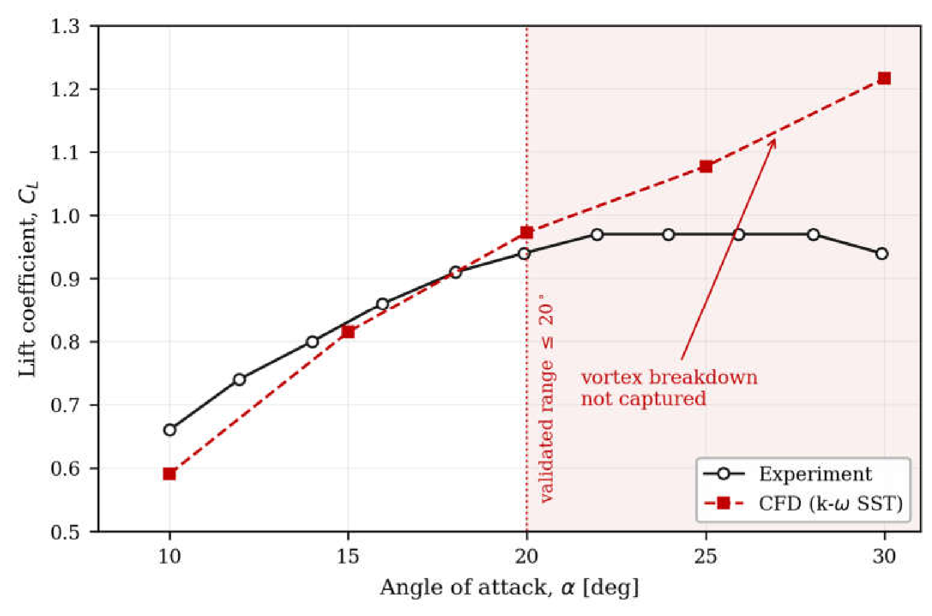
Agreement is close over the lower half of the range, to within 1.9 per cent at 15 degrees and 3.4 per cent at 20 degrees. Above 20 degrees the two curves separate. The measurement shows the lift coefficient reaching a plateau near 0.97 between 22 and 28 degrees and then falling, the signature of vortex breakdown progressing forward over the wing. The steady computation reproduces none of this: it continues to predict a rising, near-linear lift curve, reaching 1.216 at 30 degrees against a measured 0.940, an error of 29.4 per cent. This behaviour is expected of a steady Reynolds-averaged formulation, which cannot represent the unsteady breakdown of the leading-edge vortex.
The consequence for the present study is a bound on its validity rather than a defect in the model. All powered configurations reported in Section 6 are computed at 10 degrees angle of attack, well within the range in which the airframe model agrees with measurement to within 3.4 per cent. No conclusion is drawn at higher incidence.
5.2. Isolated Propeller
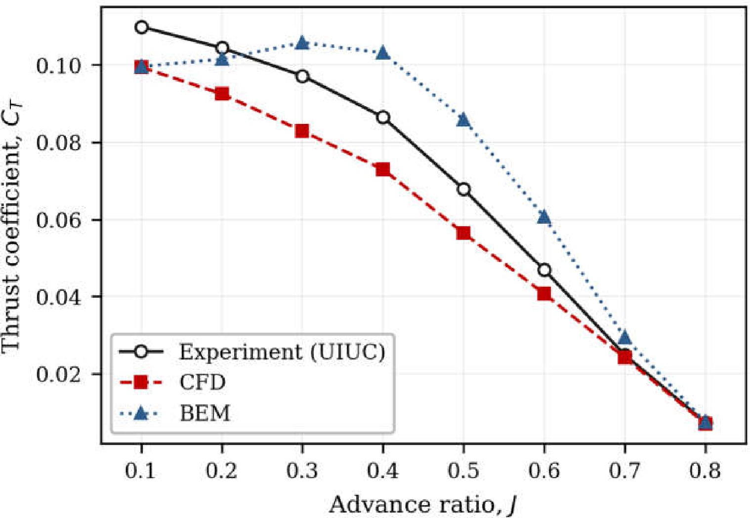
The propeller model was validated separately against measured performance of the APC 10x7 at 6500 revolutions per minute (Brandt and Selig, 2011), across advance ratios from 0.1 to 0.8. A blade element momentum solution of the same propeller is included as a second reference.
The computation reproduces the shape of the thrust curve across the whole range, including the rapid fall towards zero thrust near an advance ratio of 0.8. It under-predicts the thrust coefficient at every point, however, by a mean of 12.0 per cent between advance ratios of 0.1 and 0.7. The offset is one-sided and varies smoothly with advance ratio, which is characteristic of a small discrepancy in the blade geometry rather than of a deficiency in the turbulence treatment; a uniform error in the built pitch angle would produce exactly this signature. The blade element solution errs in the opposite direction over most of the range, so the two methods bracket the measurement, with the computational result the closer of the two.
The 12 per cent under-prediction is carried forward explicitly. Absolute thrust values reported for the puller configuration in Section 6.2 should be read as conservative by approximately that margin. The comparison between propulsion arrangements is unaffected, since both are computed with the same numerical settings on the same airframe.
Figure 8.
Thrust coefficient of the isolated APC 10x7 at 6500 RPM against advance ratio.
6. Results
6.1. Clean Delta Wing
At 10 degrees angle of attack and 30 m/s the clean wing carries 32.8 N of lift at 3.22 N of drag, giving a lift coefficient of 0.570, a drag coefficient of 0.0560 and a lift-to-drag ratio of 10.2 on the mesh adopted in Appendix B. This is the baseline against which the powered configurations are compared in Table 2.
6.2. Delta Wing with APC 10x7 Puller Propeller
The puller configuration of Figure 6 was computed at 10 degrees angle of attack with a freestream velocity of 30 metres per second and the propeller rotating at 10000 revolutions per minute. Figure 9 shows the resulting static pressure distribution on the upper surface.
The surface pressure spans approximately +395 to -1630 pascals, corresponding to pressure coefficients of +0.8 and -3.2 respectively against a freestream dynamic pressure of 514 pascals. The strongest suction is confined to a narrow band along the leading edge, marking the footprint of the leading-edge vortex, and persists from the apex to well aft along the span. Over the greater part of the upper surface the pressure sits in a moderate suction range between roughly -200 and -600 pascals, with the level rising towards the trailing edge and towards the raised centreline body.
In this configuration the wing carries 32.6 N of lift at 3.33 N of drag, a lift-to-drag ratio of 9.8.
The propeller develops 3.58 N of thrust at an advance ratio of 0.71, a thrust coefficient of 0.027. This is above the isolated-propeller value at the same advance ratio (Figure 8), consistent with the reduced inflow ahead of the airframe.
6.3. Delta Wing with the Embedded 68 mm Fan
The embedded configuration of Figure 1 was computed at 10 degrees angle of attack and a freestream velocity of 30 metres per second, with the rotor turning at 30,000 revolutions per minute. Figure 10 shows the streamwise velocity on the vertical plane of symmetry through the duct.
The rotor accelerates the flow from the freestream value of 30 metres per second to a jet that reaches 131 metres per second within the duct, with the highest velocities in the outer part of the passage swept by the blade tips. Downstream of the rotor the motor mount and guide vanes occupy the upper half of the passage in this plane, and the flow leaving them is strongly non-uniform: high-speed streams form along the upper wall and near the axis, while regions of low and locally reversed velocity appear behind the rotor hub and along the lower wall further aft. These are sources of internal loss that the present, unoptimised geometry does not address. The jet leaves the nozzle as a coherent plume that decays gradually downstream.
Outside the duct the flow remains close to the freestream value, apart from a mild acceleration into the inlet. The influence of the propulsor on the external flow is confined to the exhaust plume, which is discharged behind the airframe rather than over its surface. This is the behaviour the embedded arrangement is intended to produce. In the puller configuration of Section 6.2, by contrast, the propeller slipstream necessarily passes over the wing.
The action of the guide vanes is shown by the velocity vectors on the same plane (Figure 11). Immediately behind the rotor the vectors point in many directions, marking the swirl imparted by the blades. Downstream of the guide vanes they realign with the duct axis across the passage, and the jet that leaves the nozzle is axial: the vanes remove the swirl as intended.
The rotor develops 5.14 N of thrust inside the duct. This exceeds the combined drag of the wing, duct and guide vanes, so the configuration produces a net propulsive force at this operating point. The duct, guide vanes and motor mount add drag of their own, and for an unoptimised first prototype they are the obvious target for the next design iteration.
At 30 m/s, with the embedded 68 mm fan the wing carries 24.6 N of lift at 2.36 N of drag, against 32.6 N and 3.33 N with the puller propeller (Table 2). Both components fall, lift by 25 per cent and drag by 29 per cent: the lift coefficient falls from 0.566 to 0.427, the drag coefficient from 0.0579 to 0.0410, and the lift-to-drag ratio rises from 9.8 to 10.4.
The reduction follows from the installation. Accommodating the 68 mm duct removes part of the lifting surface of the wing centre body, and with it part of both the lift and the drag of the wing. The puller configuration retains the full wing, and its lift coefficient of 0.566 matches the clean-wing value of 0.570 at the same condition (Section 6.1), against 0.427 for the embedded fan. The 46 mm variant of Section 6.4, whose duct displaces far less of the wing surface, recovers the clean-wing lift coefficient.
The flow over the wing also differs between the two cases. In the puller configuration the propeller slipstream, faster than the freestream and highly unsteady, passes over the wing. The embedded fan discharges its exhaust behind the airframe, and the wing sees only the freestream.
6.4. Delta Wing with the Embedded 46 mm Fan
The 46 mm variant was computed at 10 degrees angle of attack and its design flight speed of 10 metres per second, with the rotor turning at 30,000 revolutions per minute. Figure 12 shows the streamwise velocity on the plane of symmetry through the duct.
As in the larger variant, the rotor accelerates the flow most strongly in the outer part of the passage, here to a peak of 61 metres per second, and regions of low and locally reversed velocity form behind the rotor hub and along the upper wall. In this variant the motor mount and guide vanes appear in the lower half of the passage. Downstream of it the flow recovers into a more uniform jet of roughly 30 to 40 metres per second that fills the duct before discharging at the trailing edge.
Outside the wing the flow remains at the freestream value apart from a mild acceleration into the inlet, and the exhaust again leaves behind the airframe. Unlike the 68 mm variant, the duct adds no protrusion below the wing.
At 10 m/s the freestream dynamic pressure is 57.1 Pa. The rotor develops 0.947 N of thrust inside the duct, more than twice the 0.43 N drag of the wing. The drag of the duct and guide vanes is smaller than the remaining 0.52 N, so, as with the larger variant, the configuration produces a net propulsive force at its design speed. The wing carries 3.67 N of lift.
In coefficient form the result confirms the expectation of Section 6.3. The lift coefficient is 0.574, against 0.570 for the clean wing and 0.566 with the puller propeller: with the smaller duct the wing recovers its full lifting capability. The drag coefficient is 0.0672, against 0.0579 with the puller and 0.0410 with the 68 mm fan, the higher value being consistent with the lower Reynolds number at 10 m/s, which raises the skin-friction coefficient. The lift-to-drag ratio is 8.5.
7. Bench Demonstrator
A prototype of the 68 mm variant and its drive was manufactured to confirm the physical feasibility of the arrangement (Figure 13). The rotor of Section 2.2 was 3D-printed in PLA and mounted directly on the motor shaft behind a spinner (Figure 13a). For the thrust measurements it was run without its duct on a commercial thrust stand (Figure 13b), at three rotational speeds in an elevated ambient temperature, for which an air density of 1.100 kilograms per cubic metre was used in the reduction.
The complete engine, with the duct and guide vanes also printed in PLA, was then assembled (Figure 13c) and run as a self-contained unit, with its battery and speed controller mounted on the outside of the duct (Figure 13d).
Figure 14.
Measured static thrust of the unducted rotor against rotational speed, with a quadratic fit.
Figure 14.
Measured static thrust of the unducted rotor against rotational speed, with a quadratic fit.
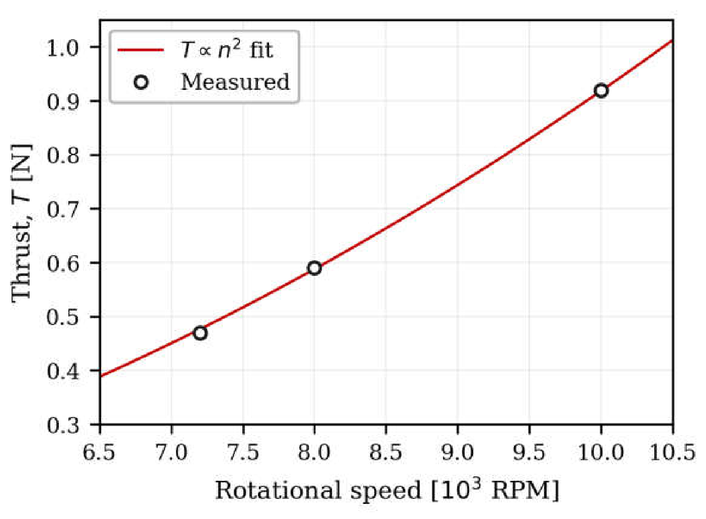
Thrust rises from 0.47 to 0.92 newtons between 7200 and 10000 revolutions per minute and follows the expected quadratic dependence on rotational speed closely: the measured ratio of thrust between the highest and lowest speeds is 1.957, against 1.929 predicted by the square of the speed ratio. The thrust coefficient, based on the 68 mm tip diameter, is correspondingly constant to within 2 per cent across the three points, at approximately 1.4.
A thrust coefficient of this magnitude, several times that of a conventional propeller, reflects the very high solidity of the rotor (Section 2.2), which behaves as an axial fan stage rather than as a propeller.
Torque and electrical power were not measured, so no efficiency or figure of merit is reported, and the complete ducted engine was run without a thrust measurement. The demonstrator establishes that the rotor operates stably under electrical load and delivers thrust consistent with its geometry, and that the complete engine can be built and run. Quantitative performance of the installed propulsor in this paper rests on the computational results of Section 6.

Table 3.
Bench measurements of the unducted rotor, 68 mm tip diameter. Density 1.100 kg/m³.
| Speed [RPM] | Thrust [N] | C_T | Tip speed [m/s] |
|---|---|---|---|
| 7200 | 0.47 | 1.39 | 25.6 |
| 8000 | 0.59 | 1.41 | 28.5 |
| 10000 | 0.92 | 1.41 | 35.6 |
8. Discussion
The two variants bracket a trade between thrust and lift. The 68 mm rotor develops enough thrust to propel the wing at 30 m/s, but its duct removes part of the lifting centre body and the lift coefficient falls by a quarter. The 46 mm rotor leaves the lift coefficient of the wing unchanged, but develops less thrust and is suited to slower flight. The rotor diameter is therefore set by the mission: the larger fan where speed matters, the smaller one where the full lifting capability of the wing must be preserved.
The comparison is made on the basis of the external flow field rather than on propulsive efficiency. The claim advanced here is that embedding the propulsor removes its influence on the aerodynamics of the airframe; whether the embedded arrangement is more or less efficient than an exposed propeller at a given power setting is a separate question, and one that cannot be settled without the thrust and torque measurements identified in Section 9.
9. Conclusions and Further Work
- An embedded micro electric ducted fan propulsion arrangement for small fixed-wing UAVs has been defined in two variants, with rotor tip diameters of 68 mm and 46 mm, and their geometry given in full.
- The airframe and propeller models were validated independently against published measurements. The delta wing agrees to within 3.4 per cent up to 20 degrees angle of attack, beyond which the steady formulation does not capture vortex breakdown; the isolated propeller reproduces the thrust curve with a consistent 12 per cent under-prediction.
- The embedded configuration was computed at 10 degrees angle of attack, 30 m/s and 30,000 RPM. The rotor develops 5.14 N of thrust inside the duct, more than the combined drag of the wing, duct and guide vanes, and the influence of the propulsor on the external flow is confined to the exhaust plume discharged behind the airframe. Against the puller configuration, wing lift and drag are both lower and the lift-to-drag ratio rises from 9.8 to 10.4.
- The 46 mm variant, whose duct is contained within the centre body of the wing, was computed at its design speed of 10 m/s. Its rotor thrust exceeds the combined drag of the wing, duct and guide vanes, and the wing recovers the clean-wing lift coefficient, 0.574 against 0.570.
- Five flat guide vanes downstream of the rotor remove the swirl, and the jet leaves the nozzle axially.
- A 3D-printed prototype of the complete engine was built and run, and its rotor, tested on a thrust stand, delivered thrust following the expected quadratic dependence on rotational speed.
Further work is required to close the experimental side of the study. The immediate priority is torque and electrical power measurement alongside thrust, so that efficiency and figure of merit can be reported, followed by testing of the fan inside its duct, validation of the computed duct flow against internal pressure and velocity measurements, and a structural assessment of the rotor at the design speed. Resolution of the 12 per cent thrust offset identified in Section 5.2, by direct measurement of the printed blade geometry, would also strengthen the propeller comparison.
Data Availability
The data supporting this study are available from the author on reasonable request.
Conflicts of Interest
The author declares no competing interests.
Appendix A. APC 10x7 Blade Geometry
The blade geometry used to construct the computational model of the APC 10x7 is reproduced below. The blade uses a NACA 4412 section outboard of 0.15 R and a Clark Y section at the root, with a tip radius of 0.127 metres.
Figure A1.
APC 10x7 chord ratio and twist distribution against radial station.

The chord distribution peaks at 0.202 R near the 40 per cent station and tapers to 0.040 R at the tip. Twist falls monotonically outboard of the 20 per cent station, from 45.8 degrees to 11.5 degrees at the tip, with the inboard rise between 0.15 R and 0.20 R reflecting the transition into the root fillet. The mean chord is 0.0186 metres, giving a blade aspect ratio of 5.80.
Table A1.
APC 10x7 blade geometry. Radial station, chord ratio and twist angle.
| r/R | c/R | β [deg] | r/R | c/R | β [deg] |
|---|---|---|---|---|---|
| 0.15 | 0.138 | 37.86 | 0.60 | 0.174 | 20.88 |
| 0.20 | 0.154 | 45.82 | 0.65 | 0.161 | 19.36 |
| 0.25 | 0.175 | 44.19 | 0.70 | 0.145 | 17.98 |
| 0.30 | 0.190 | 38.35 | 0.75 | 0.129 | 16.74 |
| 0.35 | 0.198 | 33.64 | 0.80 | 0.112 | 15.79 |
| 0.40 | 0.202 | 29.90 | 0.85 | 0.096 | 14.64 |
| 0.45 | 0.200 | 27.02 | 0.90 | 0.081 | 13.86 |
| 0.50 | 0.195 | 24.67 | 0.95 | 0.061 | 12.72 |
| 0.55 | 0.186 | 22.62 | 1.00 | 0.040 | 11.53 |
Appendix B. Mesh Sensitivity Studies
Mesh resolution for both the airframe and the propeller domain was fixed before any powered configuration was computed. The two studies are reported here in full.
B.1 Near-Wall Sensitivity, Delta Wing
Because the delta wing carries a leading-edge vortex system whose strength depends on the state of the boundary layer at separation, the sensitivity of the computed loads to near-wall resolution was examined first. Four meshes of identical topology and cell count were generated, differing only in the height of the first cell adjacent to the wall, and each was solved at 10 degrees angle of attack.
Figure B1.
Sensitivity of the delta-wing loads to first-layer height at 10 degrees angle of attack. Left: lift coefficient. Right: drag coefficient. Dashed lines mark the experimental values.
Figure B1.
Sensitivity of the delta-wing loads to first-layer height at 10 degrees angle of attack. Left: lift coefficient. Right: drag coefficient. Dashed lines mark the experimental values.
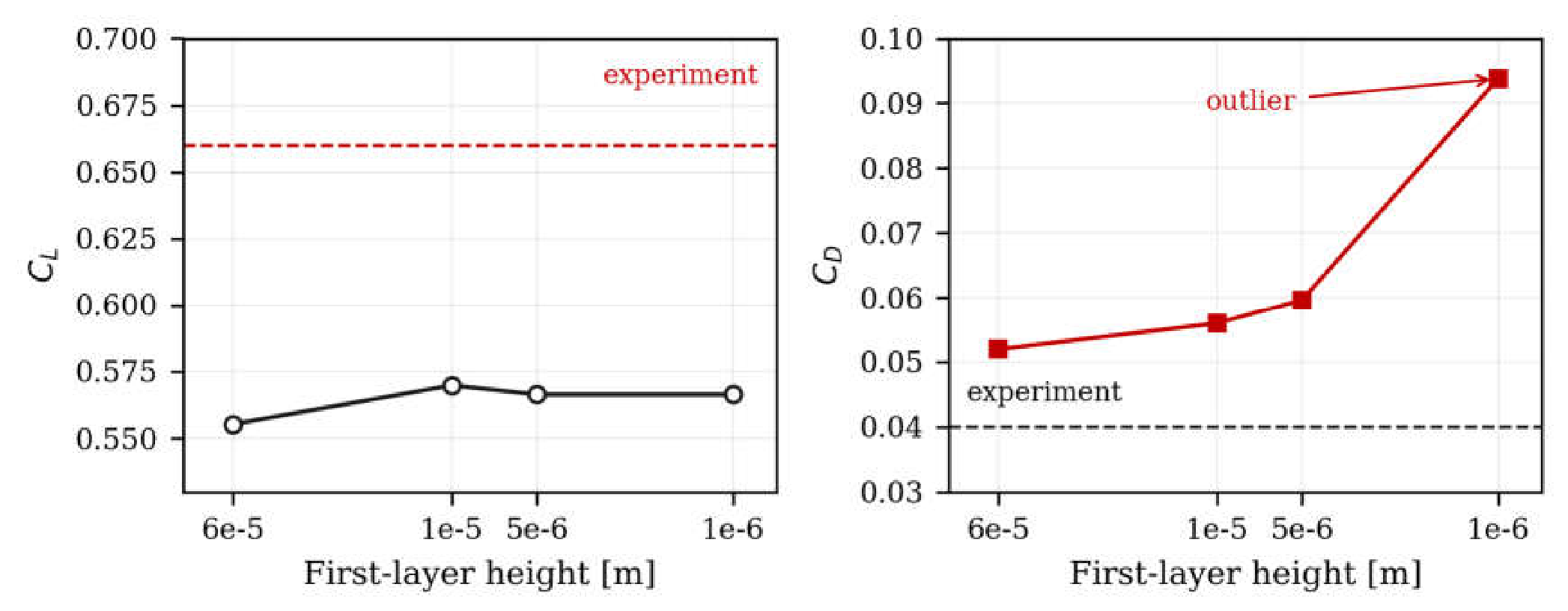
The two coefficients behave differently. Lift is essentially insensitive, varying between 0.555 and 0.570 across a sixty-fold change in first-layer height, a spread of 2.6 per cent; the pressure field that generates lift is therefore resolved on all four meshes. Drag is not insensitive. It rises monotonically from 0.052 to 0.094 as the first cell is refined, and the finest case at 1 micrometre departs sharply from the trend of the other three. That case is treated as an outlier and excluded from further use; the 1 x 10^-5 m mesh is adopted for all delta-wing computations as the coarsest resolution at which the lift coefficient has stopped changing.
This study varies wall-normal resolution alone and is reported as a near-wall sensitivity check, not as a demonstration of grid independence in the Richardson sense, since the mesh topology and total cell count were held constant throughout.
Table B1.
Delta-wing loads against first-layer height at 10 degrees angle of attack.
| First layer [m] | C_L | C_D | Note |
|---|---|---|---|
| 6 × 10⁻⁵ | 0.555 | 0.0519 | — |
| 1 × 10⁻⁵ | 0.570 | 0.0560 | adopted |
| 5 × 10⁻⁶ | 0.566 | 0.0596 | — |
| 1 × 10⁻⁶ | 0.566 | 0.0938 | outlier, excluded |
B.2 Grid Sensitivity, Isolated Propeller
An equivalent check was carried out for the propeller domain. Three meshes of 3.9, 4.3 and 5.5 million cells were solved at an advance ratio of 0.4 and 6500 revolutions per minute.
Figure B2.
Thrust coefficient of the isolated APC 10x7 at J = 0.4 against representative cell size. Labels give the
total cell count.
Figure B2.
Thrust coefficient of the isolated APC 10x7 at J = 0.4 against representative cell size. Labels give the
total cell count.
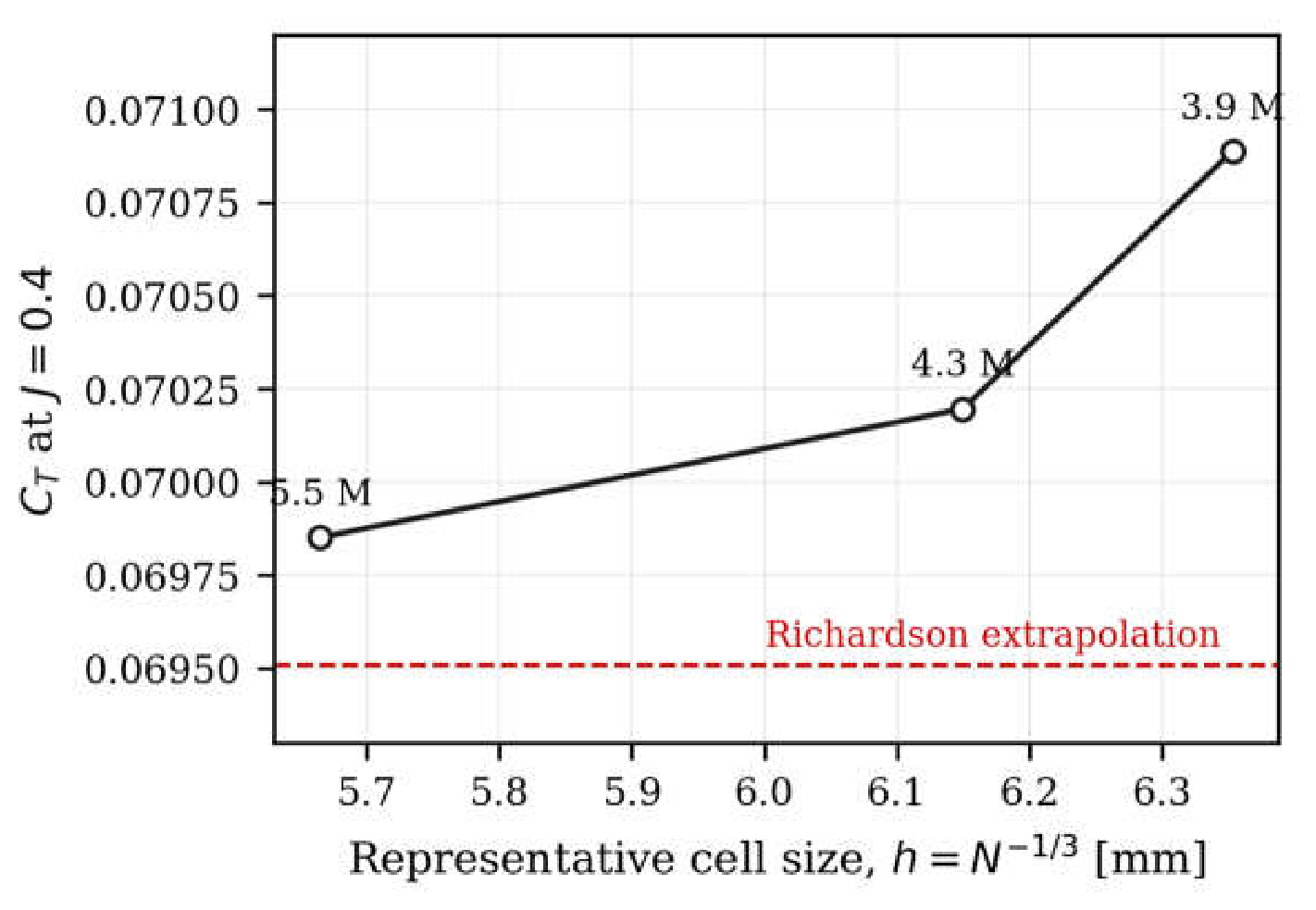
The thrust coefficient varies by 1.5 per cent over the full range of meshes tested, from 0.0709 on the coarsest to 0.0699 on the finest, and the trend is monotonic. Richardson extrapolation of the three points gives a limiting value of 0.0695, which lies 0.5 per cent below the finest solution.
The refinement ratios between successive meshes are 1.03 and 1.09, well below the value of 1.3 recommended for a formal grid convergence index (Celik et al., 2008). The result is therefore reported as a mesh sensitivity check demonstrating that the computed thrust is stable to within 1.5 per cent over the range examined, and no order of accuracy or grid convergence index is claimed from it.
Table B2.
Isolated propeller thrust against mesh density at J = 0.4, 6500 RPM.
| Cells [millions] | h = N⁻¹ᐟ³ [mm] | Thrust [N] | C_T |
|---|---|---|---|
| 3.9 | 6.36 | 4.10 | 0.070888 |
| 4.3 | 6.16 | 4.06 | 0.070196 |
| 5.5 | 5.69 | 4.04 | 0.069851 |
| extrapolated | 0 | — | 0.069508 |
Appendix C. Tabulated Validation Data
Table C1.
Computed and measured lift coefficient of the delta wing. Measured values are interpolated onto the computed angles of attack.
Table C1.
Computed and measured lift coefficient of the delta wing. Measured values are interpolated onto the computed angles of attack.
| α [deg] | C_L computed | C_L measured | Error [%] |
|---|---|---|---|
| 10 | 0.591 | 0.660 | −10.5 |
| 15 | 0.815 | 0.831 | −1.9 |
| 20 | 0.973 | 0.941 | +3.4 |
| 25 | 1.077 | 0.970 | +11.1 |
| 30 | 1.216 | 0.940 | +29.4 |
Table C2.
Computed and measured thrust coefficient of the isolated APC 10x7 at 6500 RPM, with the blade element momentum solution for reference.
Table C2.
Computed and measured thrust coefficient of the isolated APC 10x7 at 6500 RPM, with the blade element momentum solution for reference.
| J | C_T computed | C_T measured | C_T (BEM) | CFD error [%] | BEM error [%] |
|---|---|---|---|---|---|
| 0.1 | 0.0994 | 0.1099 | 0.0996 | −9.5 | −9.4 |
| 0.2 | 0.0925 | 0.1044 | 0.1015 | −11.4 | −2.8 |
| 0.3 | 0.0829 | 0.0972 | 0.1058 | −14.7 | +8.9 |
| 0.4 | 0.0730 | 0.0865 | 0.1031 | −15.7 | +19.2 |
| 0.5 | 0.0565 | 0.0679 | 0.0859 | −16.8 | +26.5 |
| 0.6 | 0.0407 | 0.0469 | 0.0607 | −13.1 | +29.4 |
| 0.7 | 0.0242 | 0.0249 | 0.0294 | −3.0 | +18.1 |
| 0.8 | 0.0072 | 0.0075 | 0.0076 | −3.8 | +1.3 |
References
- Brandt, J.B.; Selig, M.S. Propeller performance data at low Reynolds numbers. 49th AIAA Aerospace Sciences Meeting, AIAA Paper 2011-1255. Orlando, FL, 2011. [Google Scholar]
- Celik, I.B.; Ghia, U.; Roache, P.J.; Freitas, C.J.; Coleman, H.; Raad, P.E. Procedure for estimation and reporting of uncertainty due to discretization in CFD applications. J. Fluids Eng. 2008, 130(7), 078001. [Google Scholar] [CrossRef]
- Haider, B.; Mansor, S.; Mat, S.; Nasir, N. Flow characterization of low sweep MULDICON wing at low speed. Aircr. Eng. Aerosp. Technol. 2023, 95(7), 1081–1091. [Google Scholar] [CrossRef]
- Marten, D.; Wendler, J.; Pechlivanoglou, G.; Nayeri, C.N.; Paschereit, C.O. QBLADE: an open source tool for design and simulation of horizontal and vertical axis wind turbines. Int. J. Emerg. Technol. Adv. Eng. 2013, 3(3), 264–269. [Google Scholar]
- Menter, F.R. Two-equation eddy-viscosity turbulence models for engineering applications. AIAA J. 1994, 32(8), 1598–1605. [Google Scholar] [CrossRef]
- Selig, M.S.; Donovan, J.F.; Fraser, D.B. Selig, M.S., Donovan, J.F. and Fraser, D.B. (1989) Airfoils at Low Speeds. Soartech 8. H.A. Stokely, Virginia Beach.
Figure 1.
The embedded micro electric ducted fan installed in the delta-wing airframe, 68 mm variant. The 13-bladed rotor (red) is visible at the duct inlet.
Figure 1.
The embedded micro electric ducted fan installed in the delta-wing airframe, 68 mm variant. The 13-bladed rotor (red) is visible at the duct inlet.
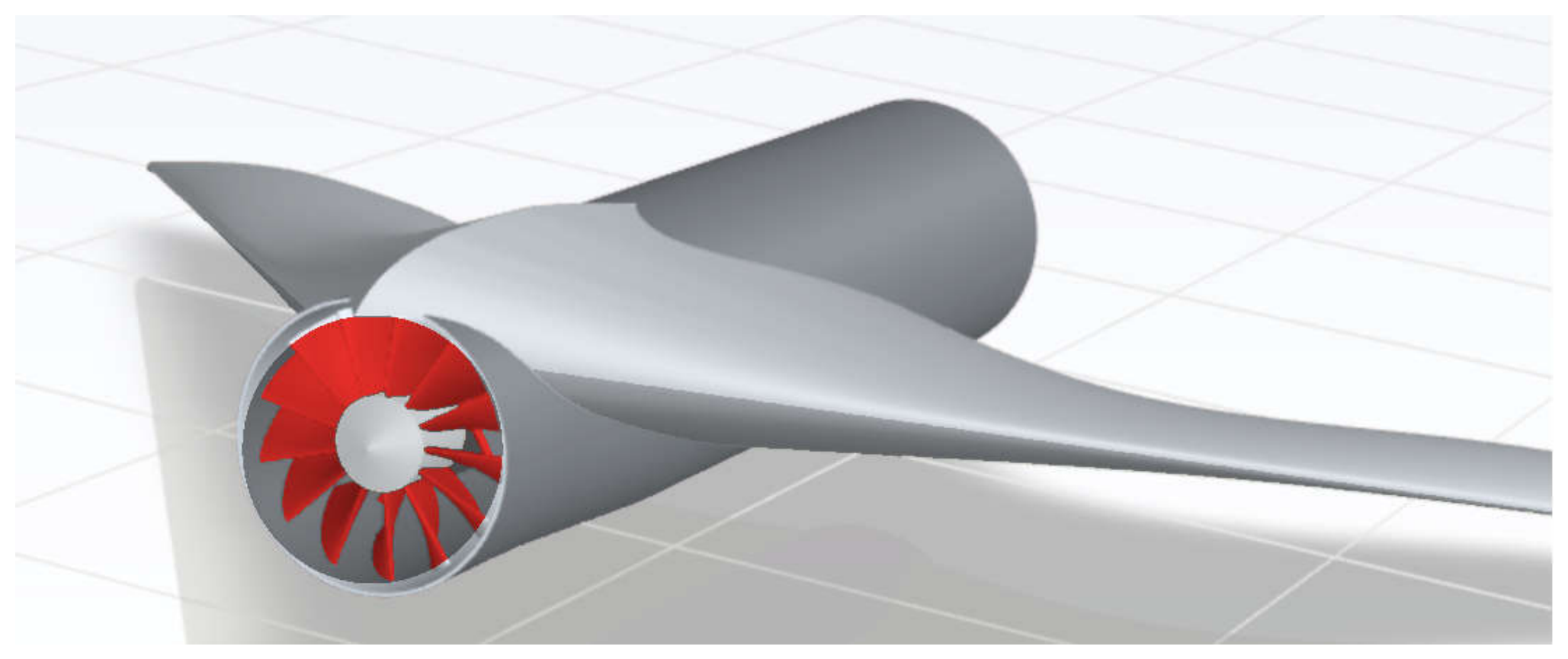
Figure 2.
The 46 mm variant: (a) duct, rotor and spinner without the wing; (b) installed in the airframe, viewed from above and behind; (c) installed, viewed from directly behind.
Figure 2.
The 46 mm variant: (a) duct, rotor and spinner without the wing; (b) installed in the airframe, viewed from above and behind; (c) installed, viewed from directly behind.
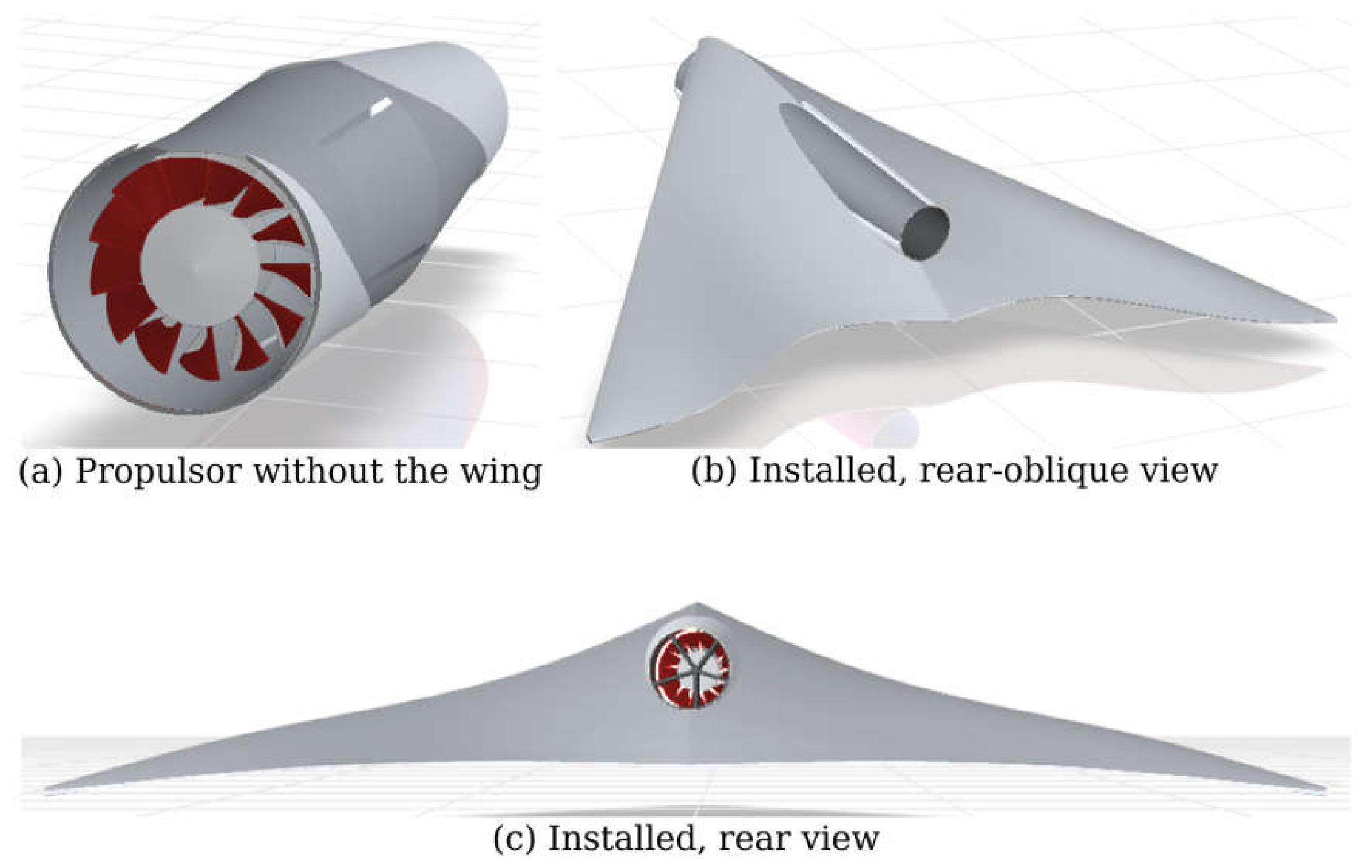
Figure 3.
The two 13-bladed rotors as built, with tips trimmed to uniform radii of 34 mm and 23 mm.
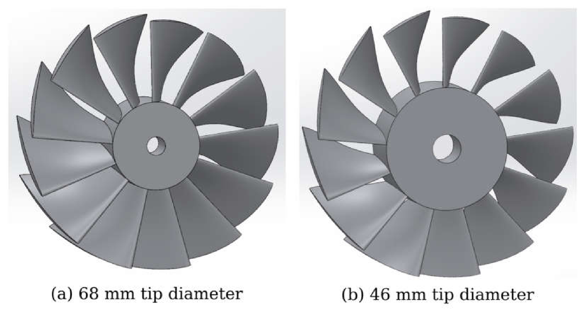
Figure 4.
The guide-vane ring: five flat radial vanes joining the motor mount to the duct wall.
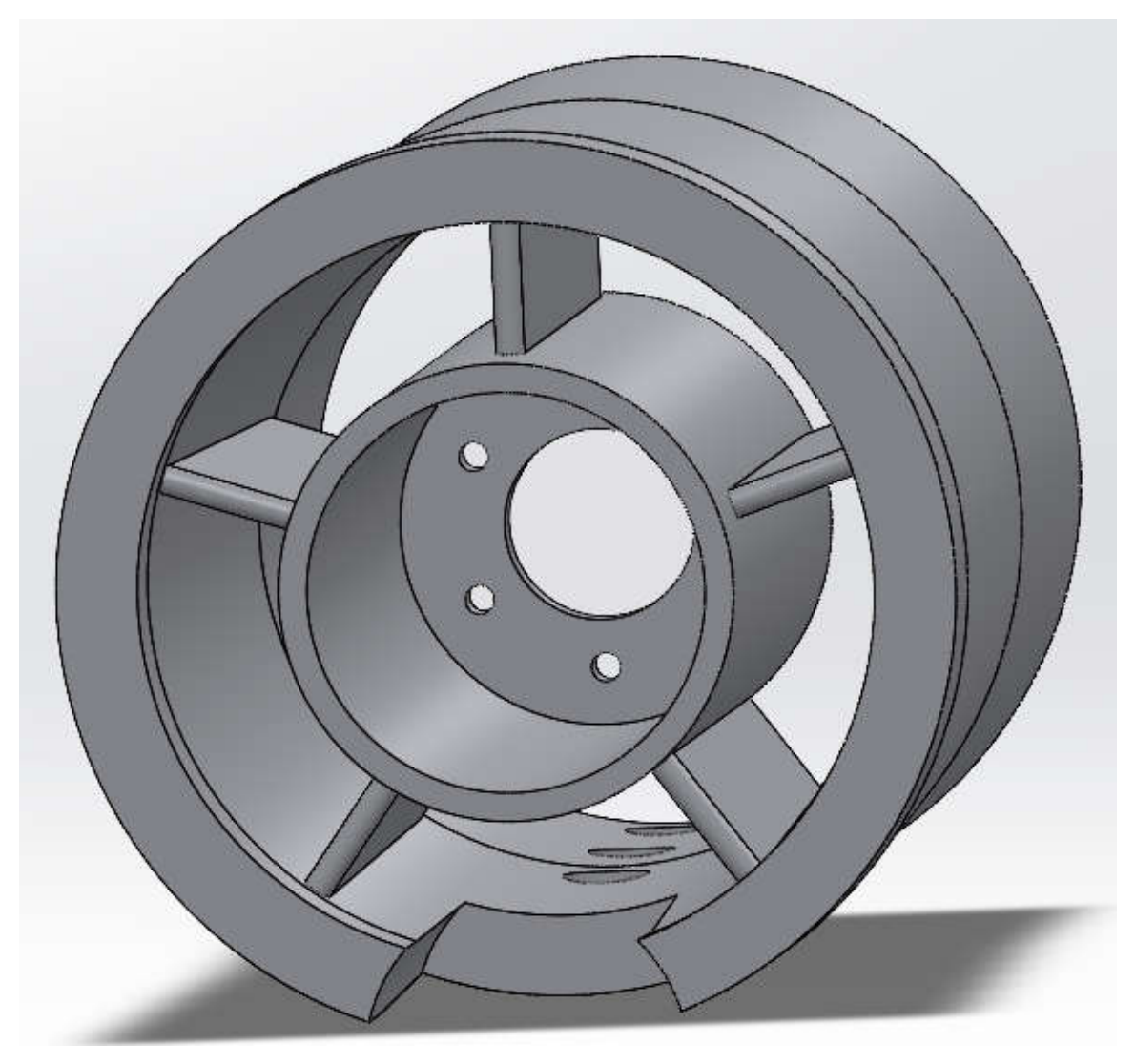
Figure 5.
Principal dimensions of the delta-wing airframe, planform view.
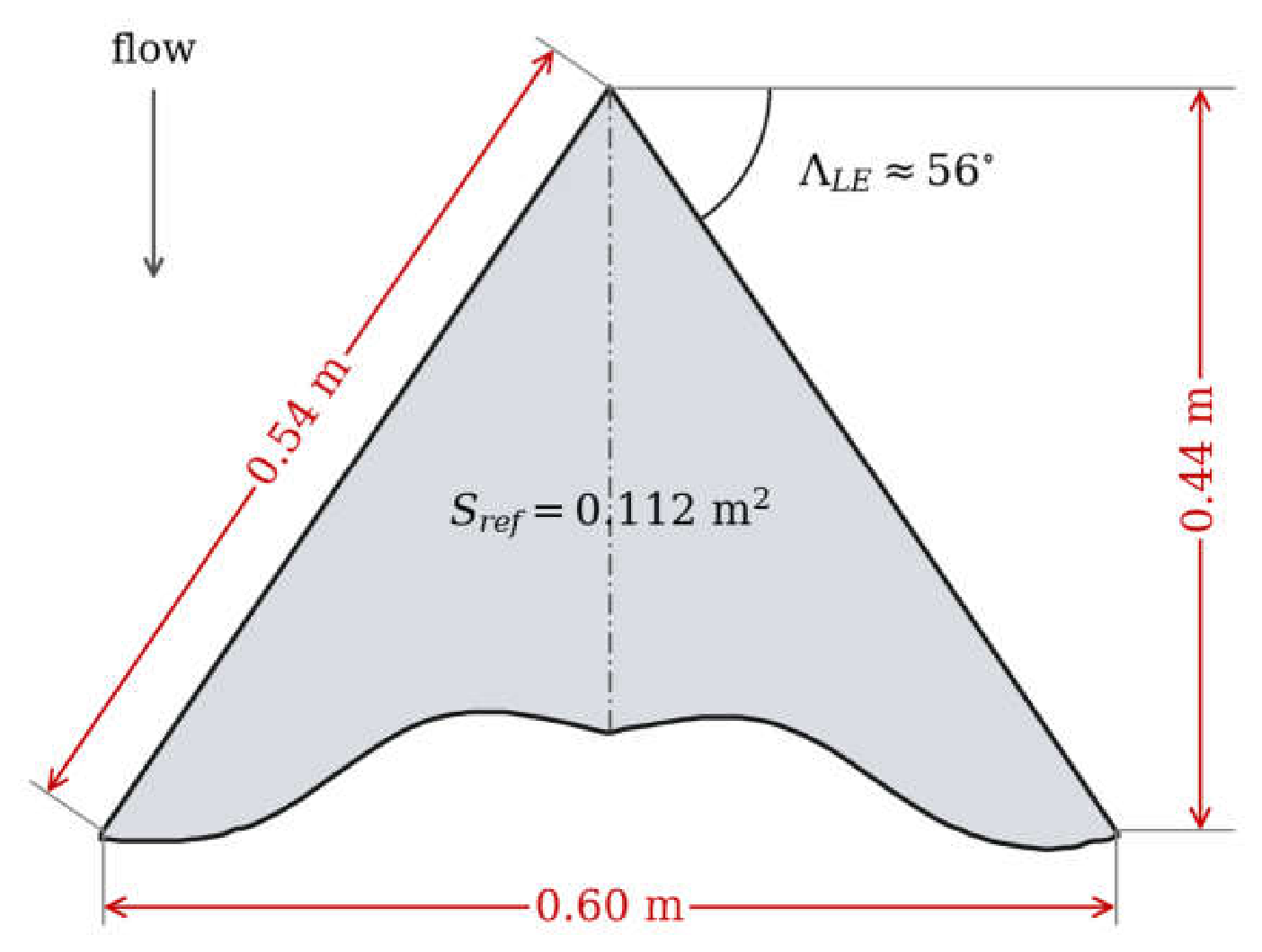
Figure 6.
Delta-wing airframe with the APC 10x7 propeller in the puller arrangement, shown at 10 degrees angle of attack.
Figure 6.
Delta-wing airframe with the APC 10x7 propeller in the puller arrangement, shown at 10 degrees angle of attack.
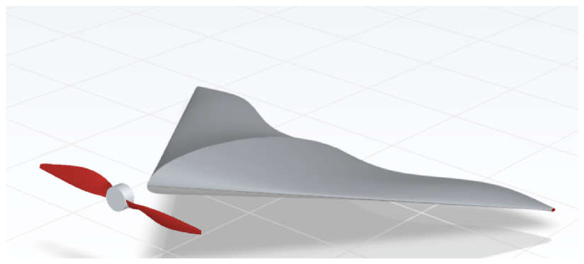
Figure 9.
Upper-surface static pressure with the APC 10x7 puller propeller operating. 10 degrees angle of attack, 30 m/s freestream, 10000 RPM.
Figure 9.
Upper-surface static pressure with the APC 10x7 puller propeller operating. 10 degrees angle of attack, 30 m/s freestream, 10000 RPM.
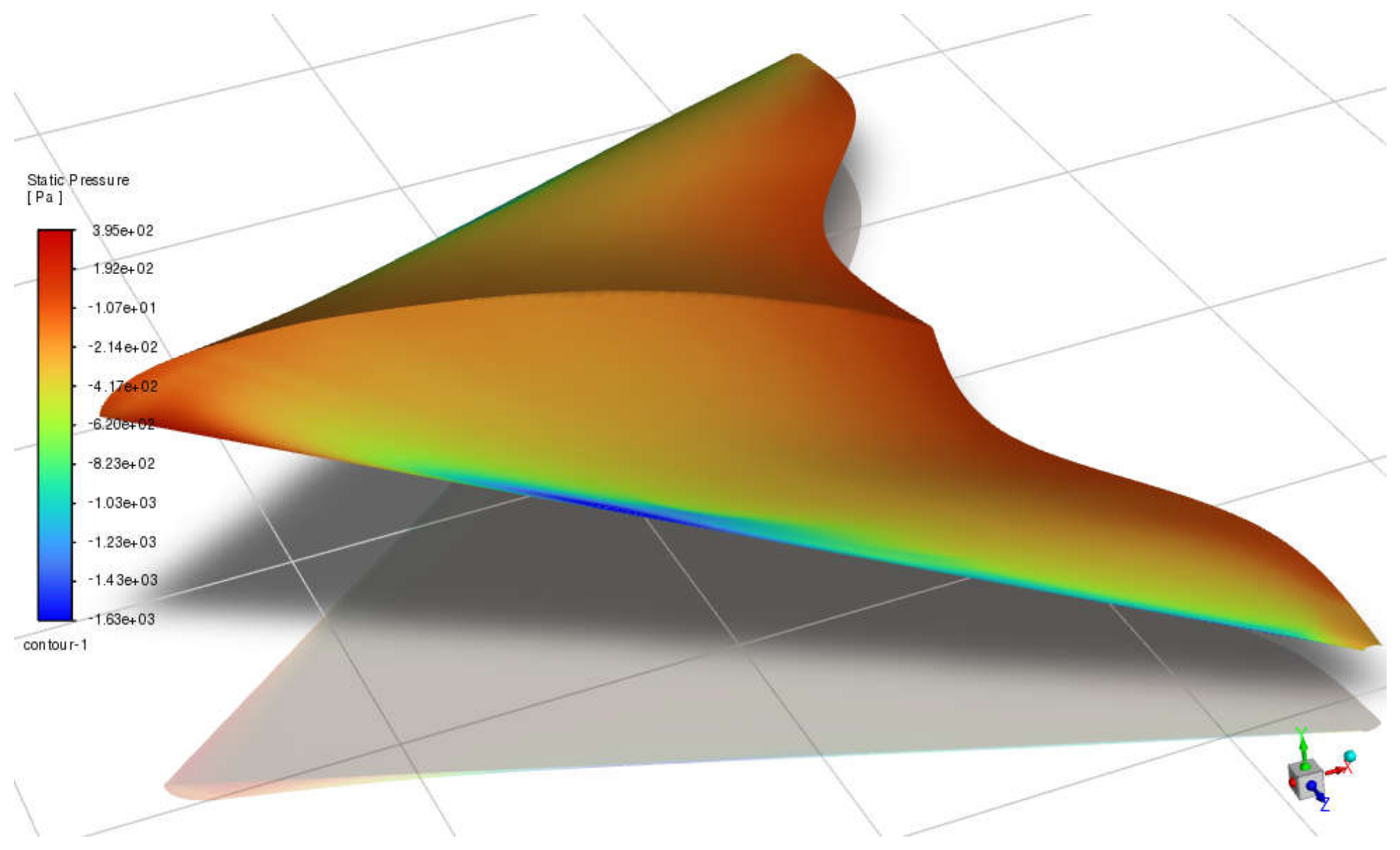
Figure 10.
Streamwise velocity on the plane of symmetry through the duct. 30 m/s freestream, 30,000 RPM.
Figure 10.
Streamwise velocity on the plane of symmetry through the duct. 30 m/s freestream, 30,000 RPM.
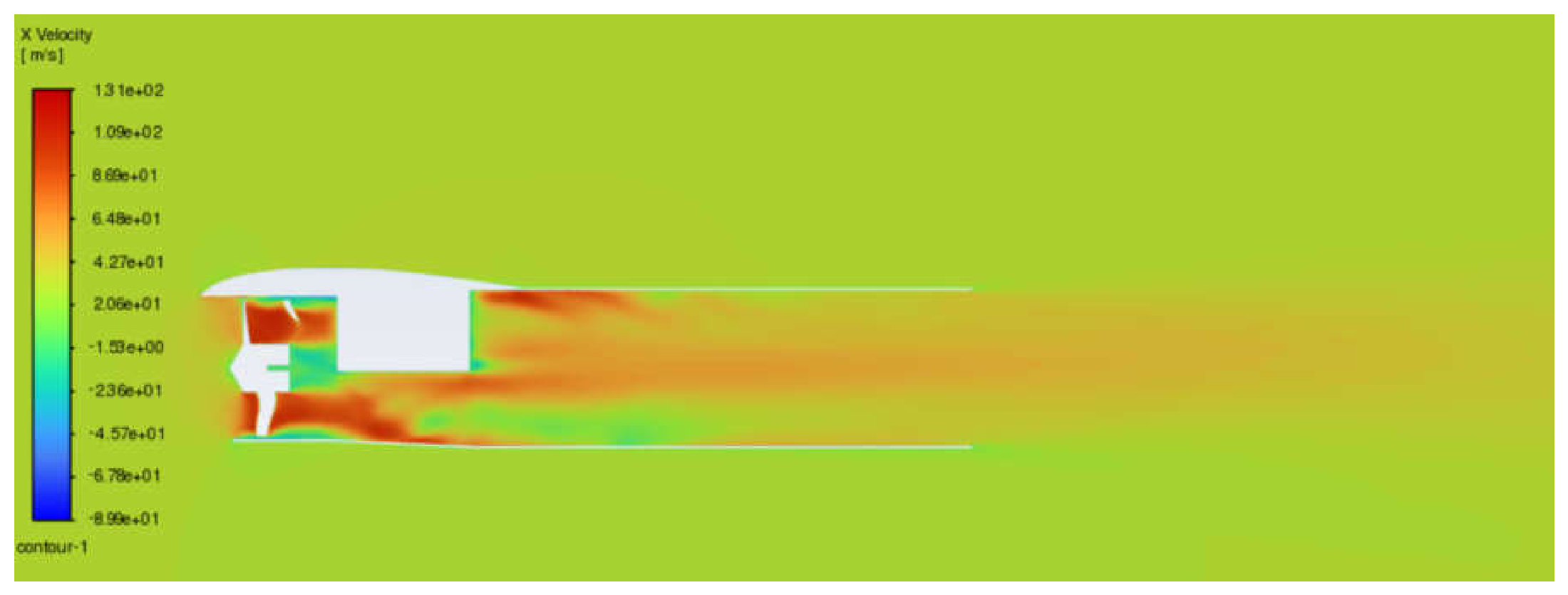
Figure 11.
Velocity vectors on the plane of symmetry through the duct of the 68 mm variant, showing the swirl behind the rotor and its removal by the guide vanes.
Figure 11.
Velocity vectors on the plane of symmetry through the duct of the 68 mm variant, showing the swirl behind the rotor and its removal by the guide vanes.
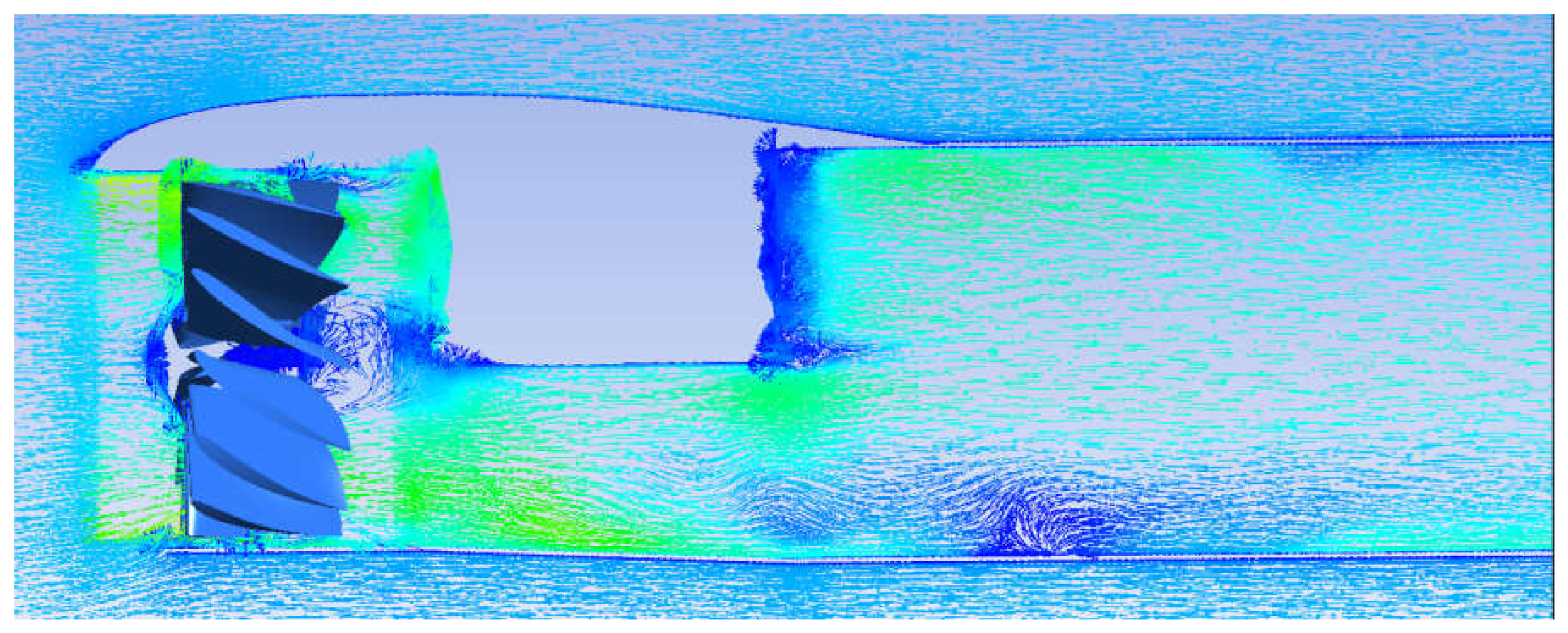
Figure 12.
Streamwise velocity on the plane of symmetry through the duct of the 46 mm variant. 10 m/s freestream, 30,000 RPM.
Figure 12.
Streamwise velocity on the plane of symmetry through the duct of the 46 mm variant. 10 m/s freestream, 30,000 RPM.
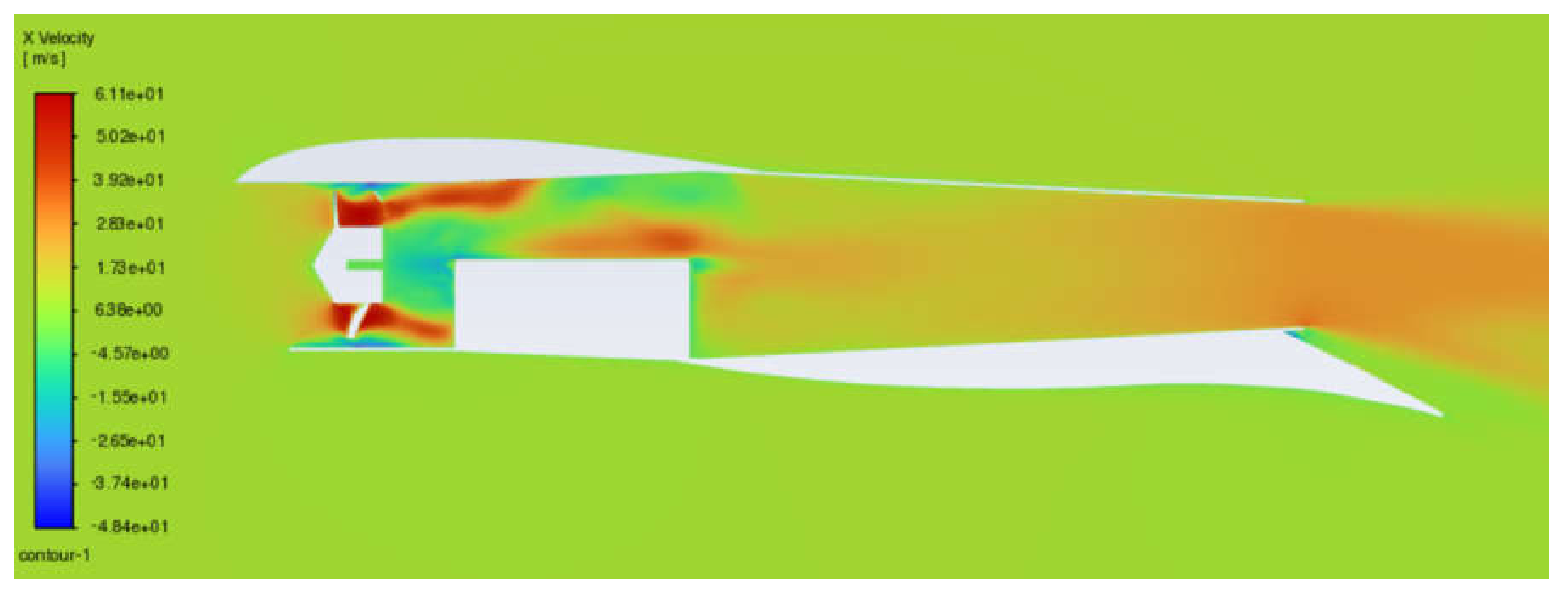
Figure 13.
The 3D-printed prototype of the 68 mm variant.
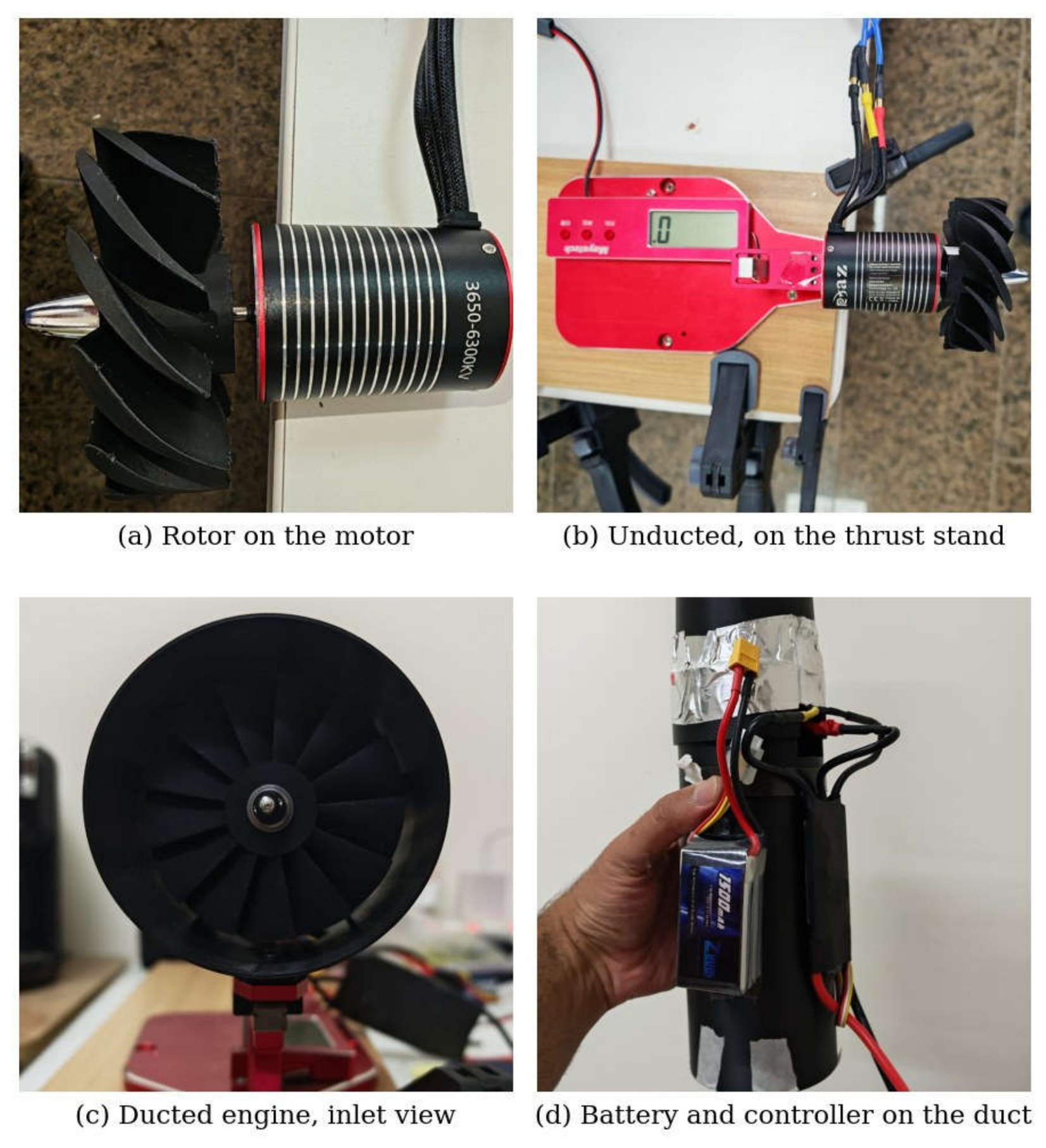
Table 1.
Rotor blade definition, SD7003 section throughout. Tips are trimmed to uniform radii of 0.034 m and 0.023 m.
Table 1.
Rotor blade definition, SD7003 section throughout. Tips are trimmed to uniform radii of 0.034 m and 0.023 m.
| Station | Twist [deg] | 68 mm: radius [m] | 68 mm: chord [m] | 46 mm: radius [m] | 46 mm: chord [m] |
|---|---|---|---|---|---|
| 1 | 80 | 0.010 | 0.024 | 0.010 | 0.012 |
| 2 | 70 | 0.019 | 0.032 | 0.014 | 0.016 |
| 3 | 55 | 0.027 | 0.040 | 0.019 | 0.020 |
| 4 | 43 | 0.036 | 0.040 | 0.023 | 0.020 |
Table 2.
Wing forces in the clean and powered configurations at 10 degrees angle of attack. Air density 1.142 kg/m³; coefficients are based on the same reference area of 0.112 m² in all cases.
Table 2.
Wing forces in the clean and powered configurations at 10 degrees angle of attack. Air density 1.142 kg/m³; coefficients are based on the same reference area of 0.112 m² in all cases.
| Quantity | Clean wing | Puller, APC 10x7 | Embedded fan, 68 mm | Embedded fan, 46 mm |
|---|---|---|---|---|
| Freestream velocity | 30 m/s | 30 m/s | 30 m/s | 10 m/s |
| Dynamic pressure | 513.9 Pa | 513.9 Pa | 513.9 Pa | 57.1 Pa |
| Rotational speed | — | 10,000 RPM | 30,000 RPM | 30,000 RPM |
| Propulsor thrust | — | 3.58 N | 5.14 N | 0.947 N |
| Wing lift | 32.8 N | 32.6 N | 24.6 N | 3.67 N |
| Wing drag | 3.22 N | 3.33 N | 2.36 N | 0.43 N |
| Lift coefficient, C_L | 0.570 | 0.566 | 0.427 | 0.574 |
| Drag coefficient, C_D | 0.0560 | 0.0579 | 0.0410 | 0.0672 |
| Lift-to-drag ratio | 10.2 | 9.8 | 10.4 | 8.5 |
Disclaimer/Publisher’s Note: The statements, opinions and data contained in all publications are solely those of the individual author(s) and contributor(s) and not of MDPI and/or the editor(s). MDPI and/or the editor(s) disclaim responsibility for any injury to people or property resulting from any ideas, methods, instructions or products referred to in the content. |
© 2026 by the author. Licensee MDPI, Basel, Switzerland. This article is an open access article distributed under the terms and conditions of the Creative Commons Attribution (CC BY) license.
Copyright: This open access article is published under a Creative Commons CC BY 4.0 license, which permit the free download, distribution, and reuse, provided that the author and preprint are cited in any reuse.