

Submitted:
17 September 2026
Posted:
17 September 2026
You are already at the latest version
Abstract
Fiber-reinforced polymer composites are attractive for load-bearing aeronautical structures, but their use near fire zones is limited by matrix pyrolysis and the loss of through-thickness integrity. Validating thermo-structural models requires temperature data from inside the laminate rather than at its boundaries. This paper reports in situ through-thickness monitoring of cross-ply carbon/epoxy (AS4/8552) laminates under one-sided flame exposure at approximately 1000 °C. Fiber Bragg Grating sensors were embedded during lay-up at 10, 50, 90 and 100 % of the thickness; temperature gratings were sheathed in 0.5 mm brass capillaries to decouple them from matrix strain, with bare gratings alongside to recover the mechanical component. Two configurations were tested: a 50-ply simply supported plate and a 30-ply plate clamped on four sides. Results are compared with a three-dimensional transient COMSOL model in which transverse conductivity and moduli switch at 673 K to represent degradation. The model reproduces the ordering, magnitude and strongly non-uniform spacing of the measured plateaus (520, 375, 290 and 290 °C), though it approaches steady state more slowly than the experiment. The simply supported plate degraded to roughly 70 % of its thickness without delamination, whereas restrained expansion in the clamped plate produced interlaminar cracking through the full thickness.
Keywords:
fire degradation
; structural health monitoring
; optic fiber sensors
; simulation
1. Introduction
Composite materials are designed to provide optimal properties for many structural applications; however, a barrier to the implementation of composites, especially in the aerospace industry, is their inherent combustibility and the associated risk of fire [1,2]. To mitigate these risks, there has been a recent industrial shift toward substituting traditional thermosetting matrices, such as epoxy, with high-performance thermoplastic matrices such as polyphenylene sulfide (PPS), since thermoplastic composites generally exhibit higher toughness, improved impact resistance, and lower moisture absorption. Furthermore, under fire conditions, thermoplastic matrices possess higher thermal decomposition temperatures, generate significant char yields, and are less susceptible to severe delamination cracking, thus retaining a superior fraction of their residual mechanical properties compared to their thermosetting counterparts [3,4,5].
Although most polymer composites are flammable, thermoplastics have long been known to show better tolerance to thermal shock than expected [6,7]. This thermal resistance is due to a combination of low thermal conductivity of the fibers, good structural integrity, and significantly, the endothermic decomposition of the matrix, which acts as a heat sink and slows down heat transmission through the laminate thickness [2,8,9]. However, the microscopic phenomena that occur within polymeric matrix composites during fire exposure are highly complex. As the matrix thermally decomposes, environmental scanning electron microscopy has revealed that microscopic pores begin to develop in the resin at temperatures around 180–200 ∘C. These heat-induced pores occur in the same temperature range where debonding of the face sheet is observed, suggesting that they act as primary crack initiation sites that drive macroscopic delamination and peeling failure [10,11].
Applications of composite materials in critical aeronautical fire zones (such as firewall boundaries near auxiliary power units) require compliance with strict certification standards, which require the ability to withstand standard flames exceeding 1100 ∘C for at least 15 minutes [12]. To satisfy these criteria, active and passive fire protection systems must be carefully designed. Traditional passive insulation schemes include the application of calcium silicate boards, vermiculite/perlite cementitious mortars, or reactive intumescent coatings that swell to form thick insulating char barriers [13,14,15]. More advanced solutions include multi-layer polymer-metal laminates that undergo controlled internal delamination and inflation during matrix gasification to dramatically lower thermal conductivity [16], or thin surface-bound glass-fiber veils impregnated with char-promoting ammonium polyphosphate to inhibit heat and mass transport of volatile gasses without degrading the mechanical properties of the core [11,17].
In order to achieve structural optimization and correct sizing in these extreme environments, it is necessary to accurately model matrix degradation and its subsequent influence on thermal and mechanical properties [2]. Although global certification standards typically focus on verifying the macro-level response of the entire structure under fire, understanding localized temperature gradients and load redistribution is crucial; under simultaneous thermal and mechanical loads, composites fail progressively [9]. In compression-loaded configurations, matrix softening (commencing above 100–150 ∘C) triggers localized plastic microbuckling and shear-induced kinking of the reinforcing plies [18,19,20]. Under tensile loading, failure is dominated by a progressive, time-dependent thermal softening of the fiber bundle itself [15]. The heating rate is highly non-uniform through the laminate thickness, often exceeding 1000 ∘C/ on the face exposed to fire while remaining below 20 ∘C/ on the cold face, and therefore, thermophysical properties (density, specific heat and thermal conductivity) vary dynamically, directly influencing structural deflection and time-to-failure [2,21].
To capture this non-linear behavior and validate advanced numerical or finite element models, experimental data must be obtained through the laminate thickness [22]. However, conventional temperature or strain sensors are highly invasive; their physical presence alters the local heat path and strain field, severely conditioning the measurements. In contrast, surface-based techniques such as infrared thermography or optical cameras are limited to boundary observations and cannot measure thermal diffusion or volumetric strain fields within the interior of the material [23].
Thus, to measure the strain field and temperature distribution inside the composite without compromising structural integrity, optical fiber sensors based on Bragg’s diffraction law are used. Fiber Bragg Grating (FBG) sensors, owing to their low weight, immunity to electromagnetic interference, and small geometric profile, can be embedded directly between individual plies inside a multi-ply laminate [24,25]. This enables precise, through-thickness monitoring of localized matrix degradation, thermal expansion, and mechanical deformation, providing the high-fidelity spatial-temporal data required to validate multi-dimensional numerical models of composites subjected to fire [1,19].
2. Methods
The specimens used in this investigation were manufactured using a high-performance aerospace-grade carbon fiber/epoxy system. The material system consists of unidirectional AS4 carbon fibers pre-impregnated with a 8552 amine-cured thermosetting epoxy matrix (AS4/8552), supplied by Hexcel Composites. To simulate localized thermal degradation and validate coupled thermo-mechanical models under controlled boundary conditions, flat 220x220 m laminate panels were fabricated, with a symmetric [0∘, 90∘, 0∘]S lay-up, and different thicknesses corresponding to 12, 20, 30 and 50 plies [1,16].
The prepreg plies were stacked and consolidated in a hot press according to the manufacturer’s recommended cure cycle to achieve a nominal fiber volume fraction of approximately 60% and a low void content below 1%.
2.1. Embedded Fiber Bragg Grating (FBG) Sensor Integration
To monitor volumetric thermal gradients and internal strain fields during fire exposure without introducing major structural defects, optical fiber sensors based on Bragg’s diffraction law were embedded directly into the laminates. Conventional sheathed thermocouples or electrical resistance strain gauges are highly invasive, introducing localized resin-rich pockets that act as crack-initiation sites and disrupt the 1D heat conduction path [18]. Conversely, Fiber Bragg Grating (FBG) sensors offer an exceptionally small geometric profile (typically 125 cladding diameter), low weight, and absolute immunity to electromagnetic interference (EMI), making them uniquely suited for in situ through-thickness telemetry in extreme environments [25].
During the hand lay-up stage, the optical fibers were carefully positioned between selected plies at predetermined through-thickness coordinates. To obtain decoupled, high-fidelity temperature measurements, specific FBG sensors were housed inside micro-capillary tubes. This configuration mechanically isolates the grating from the surrounding curing shrinkage and post-heating thermal expansion of the epoxy matrix, ensuring that the wavelength shift () is driven exclusively by thermal variations. Additional bare FBG sensors were embedded in close proximity to capture the combined thermo-mechanical strains, allowing for complete algebraic decoupling of the thermal and mechanical strain components.
2.2. Experimental Fire Testing Set-Up
To simulate the extreme thermal loading conditions representative of an in-service or post-impact aircraft cabin fire, the composite panels were subjected to one-sided radiant heating using a custom-designed bunsen burner open flame heater. The experimental setup positioned the exposed (front) face of the sample at a calibrated distance of 25 mm from the heater element, imposing a constant and uniform heat flux (25 to 75 /2) comparable to those used in ISO 5660 testing
The laminates were placed on a tripod, over an asbestos plate, allowing heat flux to flow through a small central area and minimizing boundary heat losses and ensuring a nearly adiabatic three dimensional heat conduction state in the central region of interest. The experimental set-up is shown in Figure 1, with the simply supported laminate and the flame exposed area enclosed by the asbestos plate.
The transient temperature profiles and internal strain shifts recorded by the embedded FBG sensors were captured continuously at a high sampling frequency (up to 100 Hz) using an optical sensing interrogator. As seen in Figure 2, installed sensors consist of both a temperature sensor and a deformation sensor. The temperature sensor is introduced in a 0.5 mm diameter brass tube with one end closed and the other sealed with silicone, to isolate thermal from mechanical strains. Mechanical strains can be deduced by subtracting the thermal strains from the total strains.
To turn wavelength shifts into strain or temperature changes, one nanometer deviation is equivalent to 97 ∘C or 813 ϵ, considering a linear relationship within the expected range.
Sensors are embedded at 10%, 50%, 90% and 100% in the thickness, always parallel to fiber direction, between 0∘ layers to minimize disturbance and ease adaptation during manufacturing process. A scheme of this configuration can be seen in Figure 3. In addition to the 4 FBG sensors, a thermocouple was placed at the top of the flame to verify its temperature, reaching values of around 1000 ∘C.
2.3. Simulation - FEM Model Details
The simulation was carried out by means of COMSOL®, a commercial multiphysics software which includes, among others, thermal-structural coupling. The plates are simply supported or fixed, with a 50mm square central area upon which the flame will be simulated.
The degradation of the material is taken into account above 400 ∘C, the point from which the resin modifies its properties, as shown in Table 1, and will be compared to the not degraded material.
Regarding the thermal boundary conditions, the heat flux in the flame area was imposed according to the convective heat flux equation (Eq. 1):
with . where:
- is the heat flux at the surface (heat transferred per unit area)
- h is the convective heat transfer coefficient, which depends on the fluid properties, flow conditions and geometry
- is the external temperature
- and T is the temperature of the object
On the flame area, the convective heat transfer coefficient is and the flame temperature is , which yields an initial heat flux of approximately 68 k/2. Convective flux has been considered throughout the upper face, with a convection coefficient and an ambient temperature . The remaining boundary conditions (the four lateral faces and the upper face, which is not affected by the flame) will be assumed to be thermally insulated. The mesh is built with tetrahedral elements, and it is finer in the central area to capture the thermal transverse gradients with higher accuracy.
3. Results and Discussion
The response of the laminates is governed by two coupled and competing phenomena: the progressive degradation of the epoxy matrix, which lowers the transverse conductivity and delays the advance of the thermal front, and the mechanically induced damage that develops when thermal expansion is restrained.
Throughout this section, sensor positions are quoted as a percentage of the laminate thickness measured from the flame-exposed face, so that 10 % denotes the sensor closest to the flame and 100 % the sensor at the unexposed surface. Times are referred to the instant of flame ignition.
3.1. Experimental Temperature Histories and Post-Test Condition
Figure 4 shows the through-thickness temperature histories recorded for the 50-ply, simply supported laminate. All four sensors rise steeply during the first ∼500 s and then settle onto stable plateaus of approximately 520, 375, 290 and 290 ∘C at 10, 50, 90 and 100 % of the thickness respectively. The flame was extinguished at s, after which all four channels decay towards ambient along a common curve, as expected once the internal gradient collapses.
Two features of Figure 4 are worth highlighting. First, the plateau spacing is strongly non-uniform: the drop across the first half of the thickness (∼145 K) is roughly twice that across the second half (∼85 K), and the last 10 % of the thickness sustains essentially no gradient at all. This "bowing" of the through-thickness profile is the signature of a low-conductivity layer confined to the hot side of the laminate, discussed later. Second, the plateaus are reached while the exposed face is well above the decomposition range of the 8552 matrix, i.e. a quasi-steady state is established across an already degraded hot region rather than across intact material.
A further test was performed on a 30-ply laminate clamped on all four sides by the aluminum frame shown in Figure 5 to raise the stress level sufficiently to cause delamination. Therefore, two variables were changed simultaneously with respect to the previous test: the in-plane restraint and the laminate thickness. The corresponding temperature histories are given in Figure 6. (Figure 6 gives the temperature histories from s onward. The first 75 s of the burner record cover ignition and final positioning of the specimen, over which the imposed flux is neither stable nor known, so those points are omitted. Stable exposure therefore begins at s). Because the laminate is 40 % thinner, the temperatures are considerably higher throughout: at s the 10 % and 50 % sensors read approximately 720 and 590 ∘C, and neither has reached a plateau when the record ends.
Figure 6 shows the 90 % channel dips and recovers at s, and from then on reads below the 100 % channel at the unexposed surface. A purely diffusive one-sided problem cannot invert those two stations, and the simulations do not reproduce it. An interlaminar crack passing the 90 % sensor would locally decouple it from the surrounding plies; alternatively, lateral conduction along the sensor sheath and into the aluminum frame reaches the unexposed face more directly than it reaches the interior. The perturbation is confined to a single channel and to the restrained configuration, which favors the first explanation, but the present instrumentation cannot discriminate between the two.
Figure 7 is a macrograph of the 30-ply restrained coupon after testing. Interlaminar and intralaminar cracks are present, and the degradation extends to the entire thickness to the unexposed face. By contrast, in the 50-ply simply supported coupon (Figure 8) the degraded region does not extend beyond approximately 70 % of the thickness, consistent with the 290 ∘C plateau recorded at the 90 % station, which lies below the decomposition range of the matrix.
3.2. Thermophysical Properties Scarcity and the Modeling Challenge
One of the primary challenges in validating multi-dimensional numerical models for composite degradation in fire is the severe scarcity of high-temperature thermophysical property databases in the existing literature [2,23,26]. Before the onset of pyrolysis, heat transfer through the laminate is dominated by the orthotropic properties of the intact composite, for which the thermal diffusivities reported differ by almost an order of magnitude between the fiber direction and the transverse direction ( vs. mm2/s) [6,27,28]. Once the matrix enters its decomposition range, typically 250–400 ∘C, it becomes a transient mixture of intact polymer, porous char and escaping volatiles, and the transverse conductivity falls sharply: values of order /() are reported for solid char versus /() in-plane for intact laminates [2,6,23,27].
Because temperature and conversion-dependent data for AS4/8552 are not readily available in the literature, degradation was phenomenologically represented in the present model, by switching the transverse conductivity and the transverse and through-thickness moduli at . This is a deliberate simplification and has two significant consequences in the results. First, no decomposition kinetics, mass loss, endothermic heat of decomposition or volatile transport are solved; the model is thermal and structural and the insulating effect of the char is captured only through the conductivity step. Second, the single threshold at 400 ∘C does not represent matrix softening near , which begins around 200 ∘C and is the mechanism relevant to the interlaminar failure. Therefore, the model should be expected to reproduce the temperature field better than the stress field.
3.3. Simulation Results
The transient thermal degradation process was simulated until the system reached a thermal steady-state condition. Numerical calculations were performed on a workstation equipped with an Intel Core i7 CPU and 4 GB of RAM, requiring a computation time of approximately 4 to 6 minutes to achieve convergence.
The evolution of temperature over time can be observed in Figure 9, for both materials with and without degradation in the case of a 30 plies laminate, where the four sensors reach 400 ∘C (temperature at which degradation takes place). Introducing the conductivity step redistributes the gradient in the manner expected of an insulating layer on the hot side: at s the 10 % station is approximately 30 K hotter in the degraded case, while the 50 % station is approximately 60 cooler. Heat that would otherwise be conducted inwards is retained near the exposed face, and the arrival of the thermal front at the interior stations is correspondingly delayed. However, all four stations exceed 400 ∘C within the simulated window, i.e. the entire thickness of the 30-ply laminate is predicted to degrade, as shown in the macrograph of Figure 7.
Figure 10 shows the computed temperature isosurfaces for the 50-ply laminate at . The isosurfaces are markedly elliptical, elongated along the 0∘ direction, because the in-plane conductivity along the fibers exceeds the transverse value by more than an order of magnitude. It follows that the heat transfer problem is not one-dimensional even in the center of the panel: with a 50 mm exposed zone in a 220 m plate, in-plane spreading is a first-order effect, and the through-thickness gradients reported here are those of a genuinely three-dimensional field. Figure 11 gives the y component of the stress tensor for the 30-ply restrained laminate. The influence of the restraint is confined to a band of approximately the width of the heated zone within which compressive stresses arise from constrained thermal expansion.
3.4. Comparison between Experimental and Numeric Model
Figure 12 compares the measured and computed histories for the 50-ply simply supported plate. The model reproduces the ordering of the four stations, the magnitude of the plateaus and the non-uniform spacing between them.
The model approaches its steady state more slowly than the experiment, so that the computed curves lag the measured ones over most of the transient even though the final plateaus agree. This points in the opposite direction to the insulating mechanisms emphasized above. The model, which already includes a large drop in transverse conductivity, transports heat inward too slowly rather than too quickly. Four candidate causes are consistent with the model as formulated:
- Neglected surface re-radiation and an assumed constant h. The imposed flux depends entirely on h and ; an underestimate of the effective flux during the early transient would produce exactly this lag [28].
- Overestimated insulating effect of the char. The step to 0.208 W/(m K) at 673.15 K may be too severe for a char layer that in reality shrinks, cracks and admits hot volatiles, all of which reopen conduction paths [29].
The post-test appearance of the coupon, shown in Figure 13, reproduces the elliptical geometry of the computed isosurfaces, providing an independent, if qualitative, check on the predicted in-plane anisotropy.
3.5. Boundary-Dependent Stress States: Simply Supported vs. Rigidly Restrained Configurations
Under extreme thermal gradients, the structural response and failure mechanisms of composite plates are fundamentally dictated by their mechanical boundary conditions. In accordance with thermo-structural mechanics, the total strain field () is a superposition of mechanically induced strains () and unconstrained thermal expansion () [26,35]:
In heated structures, it is strictly mechanical strains that generate stresses, while total strains drive macroscopic deflections [35]. This differentiation has critical physical implications depending on panel restraint:
- Simply Supported (SS) Configuration: In a simply supported plate with free boundary conditions, the in-plane thermal expansion is unrestricted. Consequently, total strains and thermal deflections increase freely while mechanically induced strains are minimized, meaning that induced thermal stresses remain extremely low [35]. Under these conditions, the dominant thermal phenomenon is matrix pyrolysis and char insulating behavior. Because stresses are restricted, interlaminar shear stresses do not reach the threshold required to trigger mechanical delamination cracking ahead of the char front [27].
- Rigidly Restrained (FF) Configuration: In contrast, when the panel ends are rigidly fixed, thermal expansion is completely constrained, forcing the thermal strains to be canceled by equal and opposite mechanical compressive strains, inducing severe membrane stresses. Combined with the steep non-uniform through-thickness temperature gradient, this stress state induces a highly destructive thermal moment () that drives out-of-plane bending and alters the failure envelope from Euler buckling to coupled bending-compressive kinking [19,35]. In this restrained state, the induced interlaminar shear forces easily exceed the shear strength of the matrix (which deteriorates rapidly as temperatures approach and exceed the glass transition temperature, ) [13]. This triggers macroscopic delaminations ahead of the char front [18,27].
Crucially, both matrix pyrolysis and mechanical delamination act as competitive heat transmission controllers. The development of physical delamination cracks acts as a discrete series of air gaps that dramatically decrease the effective transverse thermal conductivity of the laminate. This localized thermal barrier limits the maximum back-face temperatures and slows down overall heat transmission [26].
3.6. Microstructural Damage Kinetics and State of the Residue
The cracking visible in the macrographs is consistent with the microstructural damage sequence reported for pyrolysing thermoset matrices. Environmental scanning electron microscopy shows that pyrolysis begins with microscopic pores of the order of 5 m at 180–200 ∘C, which grow to 50–200 m and coalesce into an interconnected network that both vents volatiles and acts as a population of crack-initiation sites for ply debonding [10]. The fact that the onset of this process lies near 180 ∘C, well below the 400 ∘C threshold adopted in the FEM model, is another reason to expect the present model to predict temperatures more reliably than the onset of interlaminar damage [10].
The residue observed here is characteristic of a low-char-yield thermoset. The 8552 epoxy leaves little solid char (of the order of 18 % for thermosets [36]), so the degraded region shown consists largely of a high-void, resin-depleted fiber network with negligible fiber-matrix cohesion, and post-fire strength reductions exceeding 70 % are reported for such states [4,26,37]. This is the mechanistic origin of the interest in high-performance thermoplastic matrices noted in the Introduction: matrices such as PPS yield 46–51 % solid char and re-melt at 280 ∘C, sealing the fiber network and retaining a much larger fraction of the original properties [22]. In the present work, no thermoplastic specimens were tested and the comparison is offered only to place the residual condition observed here in context; extending the instrumentation and model to a PPS laminate is a natural continuation of this study [7].
3.7. Performance of the Embedded FBG Instrumentation
Embedded Fiber Bragg Grating (FBG) sensors provide an exceptionally low-weight alternative for measuring multi-ply physical gradients. To achieve highly accurate telemetry under thermal insult, the temperature sensor is isolated within a closed micro-capillary metallic tube to decouple thermal expansion from mechanical strain. This allows clean, decoupled thermal gradient measurements and provides the continuous spatial-temporal data required to capture the transient pyrolytic thermal front and validate multi-dimensional numerical models of composite structures subjected to fire [37,38].
Wavelength shifts were converted using 97 ∘C or 813 per nanometre, a linear sensitivity consistent with the room-temperature response of germanosilicate gratings [39]. Applied to readings above 500 ∘C this is an approximation, since the thermo-optic coefficient of silica increases appreciably with temperature [40,41]; the constant used here therefore tends to overestimate the temperature at the hot stations, and the values quoted at the 10 % station in Figure 6 should be read as upper bounds.
The temperature gratings are housed in 0.5 mm brass tubes, which mechanically decouple them from the matrix but are not negligible: in a 30-ply laminate the tube occupies of the order of 9 % of the thickness, and brass conducts at roughly 110 W/(m K), two orders of magnitude above the transverse laminate value. Each sheath therefore constitutes a conduction path running from the heated central zone towards the cooler edge, biasing the reading low; the effect is largest where the in-plane gradient is steepest.
Subject to these limitations, the sheathed FBG arrangement delivered continuous, four-station through-thickness temperature records at flame temperatures approaching 1000 ∘C, over test durations exceeding three hours, from sensors embedded during lay-up without any external penetration of the laminate. Neither sheathed thermocouple arrays, which introduce comparable or larger defects at every station, nor infrared thermography, which is restricted to the boundary, can provide equivalent volumetric data.
4. Conclusions
A satisfactory correlation was achieved between the transient finite element simulations and the experimental measurements. This agreement is particularly encouraging given the inherent challenges in characterizing temperature-dependent material properties above the glass transition temperature (), where high-temperature thermophysical data remain scarce in the existing literature, especially transverse thermal conductivities, specific heats, and decomposition kinetics.
Through-thickness heat transmission and structural integrity are governed by two competing coupled phenomena: the progressive pyrolytic degradation of the polymer matrix and the onset of heat-induced delaminations. The dominance of these mechanisms is highly sensitive to the mechanical boundary conditions of the composite panel:
- In the simply supported configuration, in-plane thermal expansion remains unrestricted. Consequently, thermally-induced membrane stresses are minimized below the threshold required to trigger mechanical delamination, leaving matrix pyrolysis and the development of an insulating char layer as the dominant thermal barrier controlling heat diffusion.
- In contrast, under rigidly fixed boundary conditions, constrained thermal expansion generates severe compressive membrane forces and bending thermal moments. These combined loads generate interlaminar shear stresses that exceed the shear strength of the softened matrix, triggering macroscopic delaminations ahead of the pyrolysis front.
Both phenomena play a critical role in the thermal response of the structure from the moment of their inception. The formation of the porous char layer and the development of delamination cracks act as localized thermal barriers by dramatically lowering the effective transverse thermal conductivity, thereby limiting the maximum back-face temperatures and delaying thermal saturation.
Finally, embedded sheathed FBG sensors have proven to be an exceptionally robust telemetry system for monitoring steep through-thickness thermal gradients. By isolating the FBG sensors within thin metallic capillary tubes to decouple thermal expansion from mechanical strain, this technique overcomes the limitations of both conventional sheathed thermocouples, which act as physical defects that weaken the laminate and surface-based thermography, which are inherently restricted to boundary observations and cannot resolve volumetric heat diffusion.
Author Contributions
Conceptualization, A.F.L.; methodology, A.F.L and A.L.M.; software, A.F.L.; validation, A.F.L., F.S.I. and A.L.M; formal analysis, F.S.I.; investigation, A.F.L, A.L.M and F.S.I.; resources, A.F.L.; data curation, A.L.M., D.R.V. and F.S.I.; writing—original draft preparation, F.S.I.; writing—review and editing, D.R.V. and F.S.I.; visualization, A.L.M. and F.S.I.; supervision, A.F.L.; project administration, A.F.L. All authors have read and agreed to the published version of the manuscript.
Funding
This research received no external funding
Data Availability Statement
Dataset available on request from the authors.
Acknowledgments
During the preparation of this manuscript, the authors used Gemini Notebook and Claude Sonnet 5 and Opus 5 for the purposes of writing and grammar. The authors have reviewed and edited the output and take full responsibility for the content of this publication.
Conflicts of Interest
The authors declare no conflicts of interest.
References
- Fernandez-Lopez, A.; Lozano Martín, A.; Güemes Gordo, A. Simulación y ensayos de materiales: degradación por fuego. In Proceedings of the ECCM16 - 16TH EUROPEAN CONFERENCE ON COMPOSITE MATERIALS, Seville, Spain, June 2014. [Google Scholar]
- Mouritz, A.P.; Gibson, A.G. Fire Properties of Polymer Composite Materials; Springer: Dordrecht, The Netherlands, 2006. [Google Scholar]
- Horrocks, A.R.; Price, D. Advances in Fire Retardant Materials; Elsevier, 2008. [Google Scholar]
- Vieille, B.; Coppalle, A. In situ interlaminar shear behavior of carbon fibers reinforced polymer composites exposed to severe thermal aggressions: PPS versus epoxy laminates. J. Thermoplast. Compos. Mater. 2025, 38, 857–877. [Google Scholar] [CrossRef]
- Vieille, B.; Ockier, A.; Philippe, D.; Davin, T.; Vacandare, J.; Barbe, F. Tensile behavior of angle ply carbon reinforced PPS laminates under severe thermal aggressions: Homogeneous and heterogeneous temperature conditions. Polym. Compos. 2024, 45. [Google Scholar] [CrossRef]
- Dodds, N.; Gibson, A.G.; Dewhurst, D.; Davies, J.M. Fire behaviour of composite laminates. Compos. Part A Appl. Sci. Manuf. 2000, 31, 689–702. [Google Scholar] [CrossRef]
- Vieille, B.; Vacandare, J.; Davin, T.; Barbe, F. Comparison of the in situ compressive behavior of carbon fibers woven ply laminates exposed to one-sided heat flux: Thermoplastic versus thermosetting composites. Polym. Compos. 2024, 45, 16511–16522. [Google Scholar] [CrossRef]
- Loh, T.W.; Nguyen, H.T.; Nguyen, K.T.Q. Prediction of temperature and structural properties of fibre-reinforced polymer laminates under simulated fire exposure using artificial neural networks. Compos. Part B Eng. 2024, 287, 111858. [Google Scholar] [CrossRef]
- Philippe, D.; Vieille, B.; Barbe, F. Modelling the gradual through thickness porosity formation and swelling during the thermal aggression of thermoplastic based laminates. Compos. Part B Eng. 2023, 266, 111026. [Google Scholar] [CrossRef]
- Goodrich, T.W.; Lattimer, B.Y. Fire decomposition effects on sandwich composite materials. Compos. Part A Appl. Sci. Manuf. 2012, 43, 803–813. [Google Scholar] [CrossRef]
- Madabhushi, A.; Pittman, C.U.; Lacy, T.E.; Kundu, S.; Priddy, M.W. A char removal protocol to visualize fiber cross-sections of carbon/epoxy composites subjected to flame. Polym. Compos. 2025, 46, 2149–2162. [Google Scholar] [CrossRef]
- Grange, N.; Chetehouna, K.; Gascoin, N.; Senave, S. Numerical investigation of the heat transfer in an aeronautical composite material under fire stress. Fire Saf. J. 2016, 80, 56–63. [Google Scholar] [CrossRef]
- Firmo, J.P.; Correia, J.R.; França, P. Fire behaviour of reinforced concrete beams strengthened with CFRP laminates: Protection systems with insulation of the anchorage zones. Compos. Part B Eng. 2012, 43, 1545–1556. [Google Scholar] [CrossRef]
- Correia, J.R.; Branco, F.A.; Ferreira, J.G. The effect of different passive fire protection systems on the fire reaction properties of GFRP pultruded profiles for civil construction. Compos. Part A Appl. Sci. Manuf. 2010, 41, 441–452. [Google Scholar] [CrossRef]
- Kandare, E.; Griffin, G.J.; Feih, S.; Gibson, A.G.; Lattimer, B.Y.; Mouritz, A.P. Fire structural modelling of fibre–polymer laminates protected with an intumescent coating. Compos. Part A Appl. Sci. Manuf. 2012, 43, 793–802. [Google Scholar] [CrossRef]
- Christke, S.; Gibson, A.G.; Grigoriou, K.; Mouritz, A.P. Multi-layer polymer metal laminates for the fire protection of lightweight structures. Mater. Des. 2016, 97, 349–356. [Google Scholar] [CrossRef]
- Kandare, E.; Luangtriratana, P.; Kandola, B.K. Fire reaction properties of flax/epoxy laminates and their balsa-core sandwich composites with or without fire protection. Compos. Part B Eng. 2014, 56, 602–610. [Google Scholar] [CrossRef]
- Ramroth, W.; Asaro, R.; Zhu, B.; Krysl, P. Finite element modelling of fire degraded FRP composite panels using a rate dependent constitutive model. Compos. Part A Appl. Sci. Manuf.;Spec. Issue Fire Behav. Compos. 2006, 37, 1015–1023. [Google Scholar] [CrossRef]
- Summers, P.T.; Lattimer, B.Y.; Case, S.; Feih, S. Predicting compression failure of composite laminates in fire. Compos. Part A Appl. Sci. Manuf. 2012, 43, 773–782. [Google Scholar] [CrossRef]
- Feih, S.; Mouritz, A. Tensile properties of carbon fibres and carbon fibre–polymer composites in fire. In Composites Part A: Applied Science and Manufacturing; Office of Naval Research (ONR): Composites in Fire, 2012; Volume 43, pp. 765–772. [Google Scholar] [CrossRef]
- Bai, Y.; Keller, T. Modeling of Strength Degradation for Fiber-reinforced Polymer Composites in Fire. J. Compos. Mater. 2009, 43, 2371–2385. [Google Scholar] [CrossRef]
- Vieille, B.; Coppalle, A.; Keller, C.; Garda, M.R.; Viel, Q.; Dargent, E. Correlation between post fire behavior and microstructure degradation of aeronautical polymer composites. Mater. Des. 2015, 74, 76–85. [Google Scholar] [CrossRef]
- Quang Dao, D.; Luche, J.; Richard, F.; Rogaume, T.; Bourhy-Weber, C.; Ruban, S. Determination of characteristic parameters for the thermal decomposition of epoxy resin/carbon fibre composites in cone calorimeter. Int. J. Hydrogen Energy 2013, 38, 8167–8178. [Google Scholar] [CrossRef]
- Abdykadyrov, A.; Tuleshov, A.; Smailov, N.; Dosbayev, Z.; Marxuly, S.; Tashtay, Y.; Yussupova, G.; Kystaubayev, N. Comparative Analysis and Optimization of Sensitivity Enhancement Methods for Fiber-Optic Strain Sensors in Structural Monitoring. Fibers 2026, 14. [Google Scholar] [CrossRef]
- Fernández-Medina, A.; Frövel, M.; López Heredero, R.; Belenguer, T.; de la Torre, A.; Moravec, C.; San Julián, R.; Gonzalo, A.; Cebollero, M.; Álvarez-Herrero, A. Embedded Fiber Bragg Grating Sensors for Monitoring Temperature and Thermo-Elastic Deformations in a Carbon Fiber Optical Bench. Sensors 2023, 23, 6499. [Google Scholar] [CrossRef] [PubMed]
- Summers, P.T.; Lattimer, B.Y.; Case, S.; Feih, S. Sensitivity of thermo-structural model for composite laminates in fire. Compos. Part A Appl. Sci. Manuf. 2012, 43, 783–792. [Google Scholar] [CrossRef]
- Mouritz, A.P.; Feih, S.; Kandare, E.; Mathys, Z.; Gibson, A.G.; Des Jardin, P.E.; Case, S.W.; Lattimer, B.Y. Review of fire structural modelling of polymer composites. Compos. Part A Appl. Sci. Manuf. 2009, 40, 1800–1814. [Google Scholar] [CrossRef]
- Lattimer, B.Y.; Ouellette, J. Properties of composite materials for thermal analysis involving fires. Compos. Part A Appl. Sci. Manuf.;Spec. Issue Fire Behav. Compos. 2006, 37, 1068–1081. [Google Scholar] [CrossRef]
- Henderson, J.B.; Wiebelt, J.A.; Tant, M.R. A model for the thermal response of polymer composite materials with experimental verification. J. Compos. Mater. 1985, 19, 579–595. [Google Scholar] [CrossRef]
- Lautenberger, C.; Fernandez-Pello, C. Generalized pyrolysis model for combustible solids. Fire Saf. J. 2009, 44, 819–839. [Google Scholar] [CrossRef]
- Gibson, A.G.; Wu, Y.S.; Chandler, H.W.; Wilcox, J.A.D.; Bettess, P. A model for the thermal performance of thick composite laminates in hydrocarbon fires. Rev. De l’Institut Français Du. Pétrole 1995, 50, 69–74. [Google Scholar] [CrossRef]
- Pitts, W.M.; Braun, E.; Peacock, R.D.; Mitler, H.E.; Johnsson, E.L.; Reneke, P.A.; Blevins, L.G. Temperature uncertainties for bare-bead and aspirated thermocouple measurements in fire environments; Thermal Measurements: The Foundation of Fire Standards; Number 1427 in ASTM Special Technical Publication; ASTM International: West Conshohocken, PA, 2003; pp. 3–15. [Google Scholar] [CrossRef]
- Beck, J.V. Thermocouple temperature disturbances in low conductivity materials. J. Heat Transf. 1962, 84, 124–132. [Google Scholar] [CrossRef]
- Bentley, R.E. (Ed.) Handbook of Temperature Measurement. In The Theory and Practice of Thermoelectric Thermometry; Springer: Singapore, 1998; Vol. 3. [Google Scholar]
- Sanad, A.M.; Rotter, J.M.; Usmani, A.S.; Gillie, M. A structural analysis of the first Cardington test. J. Constr. Steel Res. 2001, 57, 211–230. [Google Scholar] [CrossRef]
- Tranchard, P.; Samyn, F.; Duquesne, S.; Thomas, M.; Estèbe, B.; Montès, J.L.; Bourbigot, S. Fire Behaviour of Carbon Fibre Epoxy Composite for Aircraft: Novel Test Bench and Experimental Study. J. Fire Sci. 2015, 33, 247–266. [Google Scholar] [CrossRef]
- Zhou, C.; Chen, C.; Ye, Z.; Wu, Q.; Xiong, K. Multi-Directional Strain Measurement in Fiber-Reinforced Plastic Based on Birefringence of Embedded Fiber Bragg Grating. Sensors 2024, 24, 6190. [Google Scholar] [CrossRef] [PubMed]
- Yan, G.; Wan, B.; Huang, H.; Li, W. Damage and Failure Monitoring of Aerospace Insulation Layers Based on Embedded Fiber Bragg Grating Sensors. Polymers 2024, 16, 3543. [Google Scholar] [CrossRef] [PubMed]
- Flockhart, G.M.H.; Maier, R.R.J.; Barton, J.S.; MacPherson, W.N.; Jones, J.D.C.; Chisholm, K.E.; Zhang, L.; Bennion, I.; Read, I.; Foote, P.D. Quadratic Behavior of Fiber Bragg Grating Temperature Coefficients. Appl. Opt. 2004, 43, 2744–2751. [Google Scholar] [CrossRef] [PubMed]
- Mihailov, S.J. Fiber Bragg Grating Sensors for Harsh Environments. Sensors 2012, 12, 1898–1918. [Google Scholar] [CrossRef] [PubMed]
- Laffont, G.; Cotillard, R.; Ferdinand, P. Multiplexed Regenerated Fiber Bragg Gratings for High-Temperature Measurement. Meas. Sci. Technol. 2013, 24, 094010. [Google Scholar] [CrossRef]
Figure 1.
Experimental set-up of the composite material laminate exposed to fire.
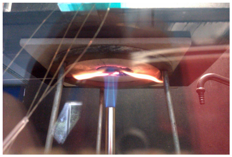
Figure 2.
Scheme of temperature and strain FBG sensor.
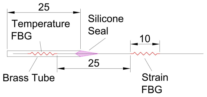
Figure 3.
Scheme of positioning of FBG sensors.
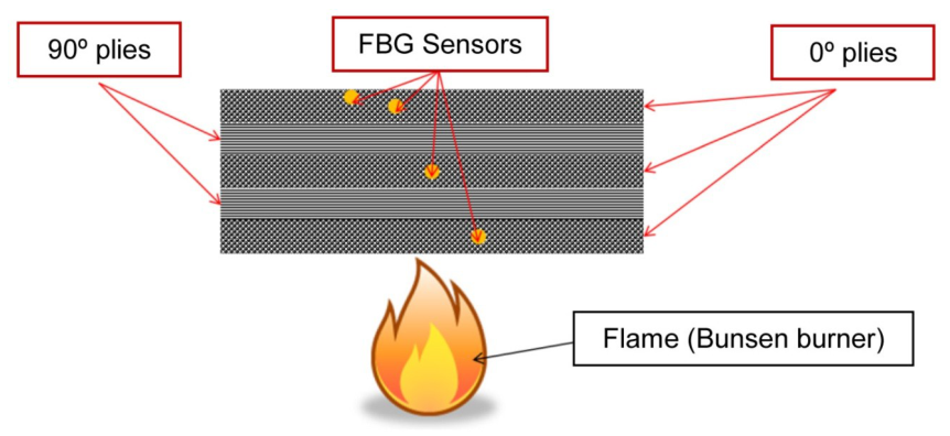
Figure 4.
Temperature versus time profile for the 50 plies laminate.
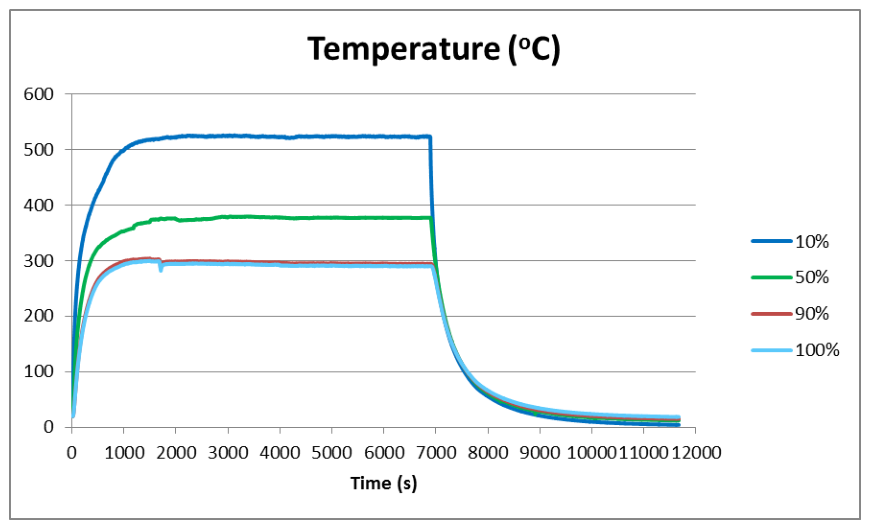
Figure 5.
Laminate with aluminum frame that simulates a four sides constraint.
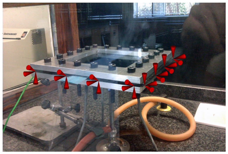
Figure 6.
Temperature versus time profile for the 30 plies laminate.
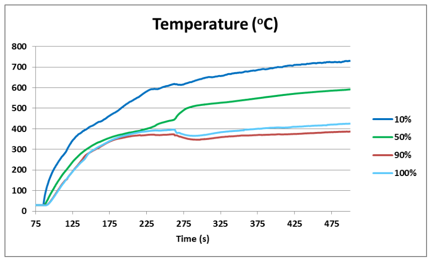
Figure 7.
Macrograph after fire test for the 30 plies, four sides fixed laminate.
Figure 8.
Macrograph after fire test for the 50 plies laminate.

Figure 9.
Temperature versus time simulated profile for the 30 plies, 4 sides fixed laminate. Continuous line corresponds to material with degradation condition, while dashed is for non-degraded.
Figure 9.
Temperature versus time simulated profile for the 30 plies, 4 sides fixed laminate. Continuous line corresponds to material with degradation condition, while dashed is for non-degraded.
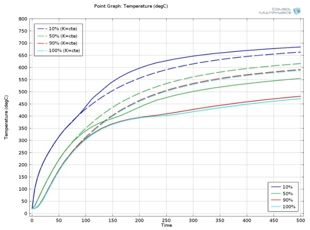
Figure 10.
Temperature isosurfaces for the 50 plies laminate.
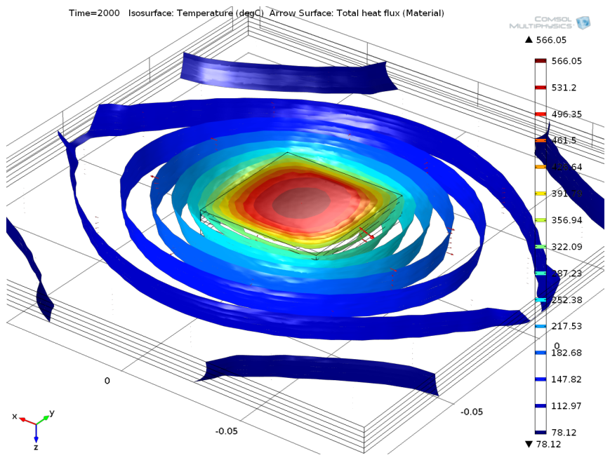
Figure 11.
Stress tensor, ‘y’ component, for the 30 plies, 4 sides fixed laminate.
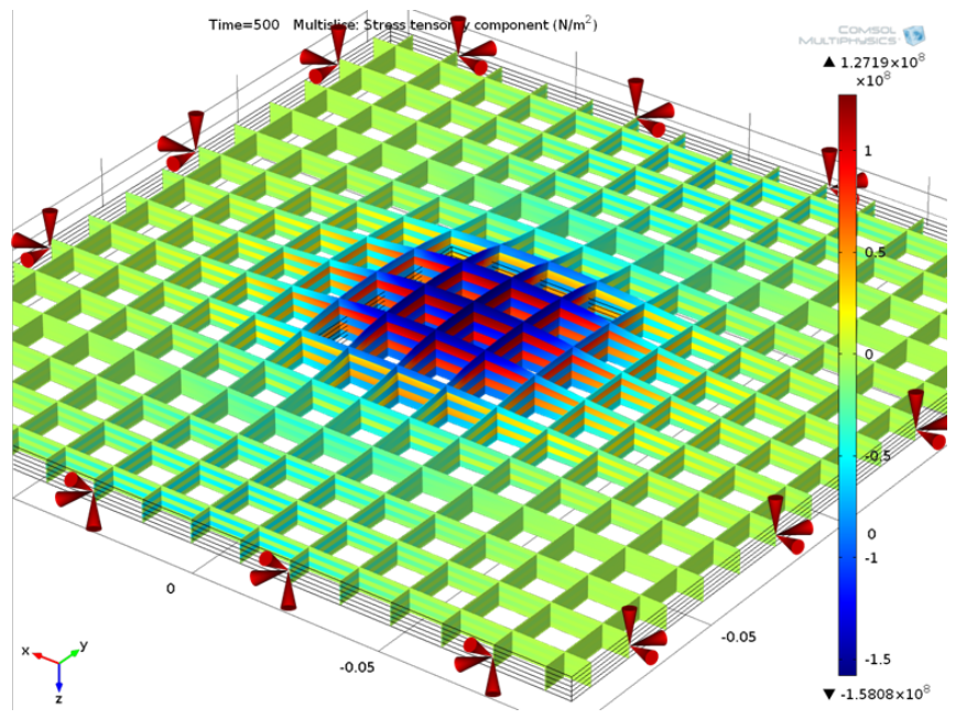
Figure 12.
Comparison between experimental (dashed) and numeric model (continuous), for the 50 plies plate.
Figure 12.
Comparison between experimental (dashed) and numeric model (continuous), for the 50 plies plate.
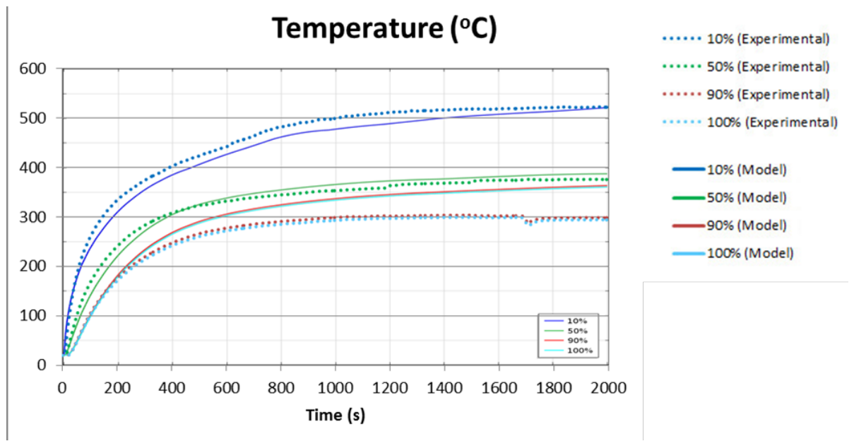
Figure 13.
Photo of the degraded specimen after the test.
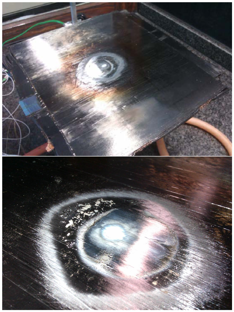

Table 1.
Relevant parameters used in the model.
| Property /Direction | X (0∘ ) | Y (90∘ ) | Z (through thickness) |
|---|---|---|---|
| C.T.E. () [ ϵ/] | -0.47 | 30 | 30 |
| Thermal Conductivity (K) [W/(mK)] | 5.5 | If T < 673.15 : 0.865 If T >= 673.15: ((2.83e-4)*(T-273)+0.0949) | If T < 673.15: 0.865 If T >= 673.15: ((2.83e-4)*(T-273)+0.0949) |
| Young’s Modulus (E) [GPa] | If T < 673.15: 130If T >= 673.15: 13 | If T < 673.15: 8 If T >= 673.15: 1 | If T < 673.15: 8 If T >= 673.15: 1 |
Disclaimer/Publisher’s Note: The statements, opinions and data contained in all publications are solely those of the individual author(s) and contributor(s) and not of MDPI and/or the editor(s). MDPI and/or the editor(s) disclaim responsibility for any injury to people or property resulting from any ideas, methods, instructions or products referred to in the content. |
© 2026 by the authors. Licensee MDPI, Basel, Switzerland. This article is an open access article distributed under the terms and conditions of the Creative Commons Attribution (CC BY) license (http://creativecommons.org/licenses/by/4.0/).
Copyright: This open access article is published under a Creative Commons CC BY 4.0 license, which permit the free download, distribution, and reuse, provided that the author and preprint are cited in any reuse.