

Submitted:
16 September 2026
Posted:
17 September 2026
You are already at the latest version
Abstract
Fifth metacarpal shaft fractures account for a large share of hand trauma and often re-quire operative internal fixation, yet conventional dorsal plates and cannulated screws present a stiffness mismatch with native bone and mechanically preclude active, piezo-electric coatings. This study presents the design, fabrication, and functional characteri-sation of a low-profile, 4D piezoelectric dorsal plate for the fifth metacarpal bone. A curved, 0.5 mm plate was modelled in SolidWorks and overlaid with a randomised De-launay lattice in Meshmixer, achieving 73.6% porosity and quasi-isotropic yield behav-iour via a 70% mesh-reduction strategy. Finite element analysis under a 300 N load, using MED610 biocompatible resin properties, confirmed structural integrity with a 4.083 mm peak deflection and no localised buckling. Implants were manufactured by masked stereolithography (Anycubic Photon Mono, 20 μm layers), achieving 98.75% average dimensional accuracy. A barium titanate precursor was synthesised via the propionate route and deposited through a three-cycle, low-temperature submersion process. FTIR confirmed molecular bonding between cations and the polymer matrix, while micros-copy verified a continuous, pore-preserving coating. Under cyclic compressive loading (1–2 N), the implant generated an alternating open-circuit voltage of 0.3–0.7 V. These results demonstrate an accessible stereolithography route to active, self-stimulating or-thopaedic hardware.
Keywords:
metacarpal implant
; 4D printing
; masked stereolithography
; Delaunay lattice
; barium titanate
; piezoelectric coating
; bone tissue scaffold
1. Introduction
Hand injuries represent one of the most frequent reasons for emergency room admissions worldwide, commonly resulting from direct trauma or falls onto an outstretched hand. Within hand anatomy, metacarpal fractures are the most prevalent, comprising between 18% and 44% of all hand-related skeletal injuries [1]. Among the five metacarpal bones, clinical data reveals that the fifth and smallest metacarpal bone is particularly fragile and statistically the most prone to fracture localisation across all patient age groups, accounting for 49% of all metacarpal fractures in patients under 16 years of age and escalating to 58% in adults over 16 [2]. While fractures located at the neck or base of the metacarpal are frequently managed using non-operative methods, fractures sustained along the bone shaft require operative internal fixation in 43.2% of cases [1]. This emphasises that injuries along the length of the fifth metacarpal bone shaft present a clear clinical requirement for specialised surgical remediation hardware.
Historically, open reduction and internal fixation (ORIF) of metacarpal shaft fractures has relied on surface-mounted dorsal plates for skeletal alignment, such as the Stryker Profyle 3D line [3]. Although effective at suppressing fracture non-unions and preventing excessive malunions, conventional plate profiles require extensive disruption of the enveloping soft tissue and aggressive periosteal stripping during surgical exposure, which severely impairs local vascularity and delays cortical bone regeneration [4]. Furthermore, standard metallic plates create a massive mechanical mismatch between the plate and the native bone (10-30 GPa), inducing the stress shielding effect that causes the underlying bone to atrophy and resorb due to lack of physiological loading, as that is taken over entirely by the implant [5]. Additionally, the prominent physical profile of legacy hardware generates chronic extensor tendon friction during normal finger movement, which may lead to painful tissue adhesions or tendon rupture [4].
To address these complications, contemporary orthopaedics leverage vat photopolymerization manufacturing methods to fabricate low-profile, patient-specific implants featuring compliant metamaterial architectures that closely resemble native bone stiffness without compromising primary yield strength [6,7,8]. Concurrently, integrating smart perovskite ceramics such as barium titanate (BaTiO3 / BTO) introduces 4D printing capabilities, allowing open porous networks to accelerate osseointegration through acute-angle cell clustering while converting physiological movement into electrical stimuli [9,10,11]. Because bone is naturally piezoelectric from its collagen structure, dynamic post-operative deflections trigger bioelectrical surface potentials that open voltage-gated calcium channels, actively promoting osteogenesis and rapid fracture bridging [12,13,14]. Applying a perovskite coating to a low-profile curved dorsal plating system bypasses limitations found in cannulated compression screws (CCS), such as aggressive thread friction and intense static torsional forces during insertion that may shear and delaminate the BTO thin films [15,16,17]. Functioning instead as an additional surface-level architecture positioned along the tension side of the metacarpal, the proposed plate avoids installation shear entirely while safely converting dynamic post-operative bending deflections into continuous electrical charge to enhance bone regeneration [18,19]. Building on this rationale, the present study designs, manufactures, and functionally validates a 4D smart dorsal plate for the fifth metacarpal bone. The implant combines a randomised, reduction-decimated Delaunay lattice — engineered for quasi-isotropic, bending-dominated yield behaviour rather than the layer-collapse failure typical of periodic unit cells — with a barium titanate coating applied through a low-temperature cyclic submersion process that promotes direct chemical bonding between Ba2+ cations and the polymer resin matrix. The two central contributions of this work are therefore (i) the constructive-technological design of the CAD/lattice implant geometry and its mechanical validation, and (ii) the chemical synthesis, deposition, and functional characterisation of the BTO piezoelectric coating on the printed scaffold.
2. Materials and Methods
2.1. Design and Fabrication of the CAD Metacarpal Implant
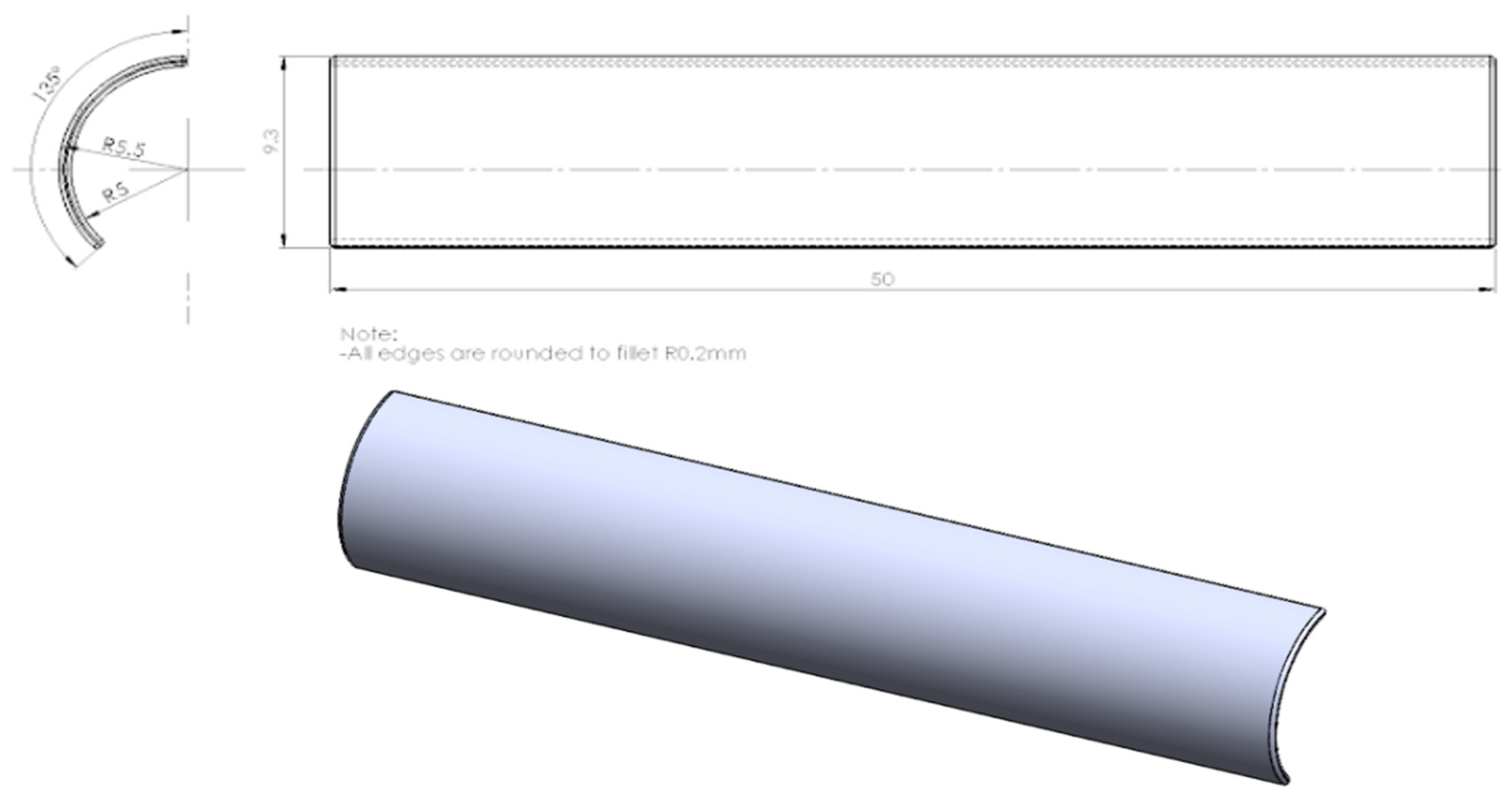
The base shape was created as a C-shaped cross-section extruded into a cylindrical sector mirroring the natural dorsal curvature of the fifth metacarpal, with sharp edges rounded to an R0.2 mm fillet to eliminate stress concentrators and smooth the tissue-contact surface. Sizing parameters were derived from clinical averages: an internal radius of 5 mm and an overall length compatible with the average 52.3 mm length of the Metacarpal-5 bone [2]. A minimal thickness of 0.5 mm was selected so that the plate sits functionally flush beneath the soft tissue, mitigating extensor tendon friction; this thin-wall precision is achievable owing to the high resolution of the MSLA printing process described in Section 2.3. The model was then partitioned into a central active zone, which would host the porous lattice scaffold, and two lateral technological zones intended for fastening hardware.
Figure 1.
(Bottom) The primordial CAD model of the metacarpal implant; (Top) Technical Drawing.
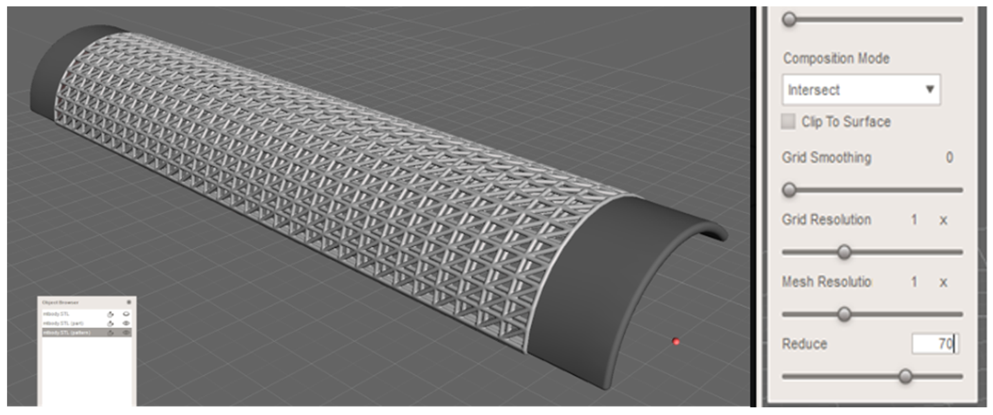
Conventional periodic lattices, such as cubic unit cells, are highly anisotropic: loaded parallel to their struts (α = 0°) they behave rigidly in a stretch-dominated mode, but a 15-30° change in load angle triggers strut bending and a sharp drop in yield strength [19] a serious limitation for hand hardware, which is routinely subjected to shear and off-axis loading. The Delaunay mesh instead behaves as a redundant, body-centred-cubic-like grid with struts oriented along both α = 0° and α = 45°, keeping most struts in tension or compression rather than bending across the loading range and giving a stretch-dominated response at any orientation [19]. Left unmodified, a fully periodic Delaunay mesh can still fail through sequential horizontal layer collapse, visible as cyclical stress dips once one load-bearing layer fails before the layer beneath begins carrying load [19]. This was addressed by manipulating the “Reduce” parameter in Meshmixer from 100% to 70%, deliberately breaking the aligned planes of the periodic triangulation.
Figure 2.
(Left) The finalised mesh model; (Right) Reduction coefficient set to 70% in the “Make Pattern” menu.
Figure 2.
(Left) The finalised mesh model; (Right) Reduction coefficient set to 70% in the “Make Pattern” menu.
2.2. Barium Titanate (BTO) Piezoelectric Coating
To prepare the BaTiO3 (BTO) coating solution, barium propionate and titanium (IV) isopropoxide were combined in a stoichiometric, equimolar ratio. The barium propionate solution was first synthesised through the propionate route at room temperature, using a mixture of barium acetate, methanol (CH3OH), propionic acid (CH3CH2COOH), and ammonia (NH4OH); propionic acid was chosen specifically for its low, 140 °C boiling point to simplify processing. The barium propionate solution was then mixed with a titanium (IV) isopropoxide solution (boiling point 232 °C), and the total concentration of the combined precursor mixture was adjusted to 0.2 M [11]. To achieve a uniform and dense distribution of the BTO precursor solution across the printed scaffolds, a cyclic submersion coating procedure was used, alternating liquid immersion with thermal evaporation and ambient thermal relaxation. The printed scaffold was submerged in the BTO solution for 3 minutes to allow the liquid to penetrate the Delaunay lattice and fully envelop the structural struts. After removal and drainage of excess liquid, the sample was placed on a ceramic plate and transferred into a drying oven at a constant 120 °C for an initial 25-minute heating phase, then allowed to rest at room temperature for ~5 minutes to prevent internal thermal stress from cracking the newly deposited layer before the next immersion. The second and third coating cycles were performed identically to the first, but with a shortened 15-minute thermal treatment, targeting micro-imperfections in the homogeneity of the preceding layer. This multi-stage, low-temperature procedure ensured sufficient thermal energy to fully consolidate the deposited BTO and evaporate volatile organic carriers or residual propionic acid, without inducing thermal degradation, warping, or plastic deformation of the underlying polymeric resin scaffold.
2.3. Characterisation Techniques
Dimensional fidelity of the printed scaffold was assessed with a high-resolution Optika optical microscope, comparing three nominal CAD dimensions the technological zone width (A) and the length (B) and height (C) of a Delaunay unit cell against the corresponding measurements on the printed part, the latter two averaged across multiple cells to exclude outliers. Accuracy per variable was calculated as one minus the relative deviation between the nominal and measured value, expressed as a percentage. Post-coating surface characterisation used the same optical microscope to compare a BTO-coated sample against an uncoated control, examining surface sheen, transparency, and cross-sectional strut and pore integrity. Chemical bonding of the deposited coating was assessed by FTIR, comparing the BTO-coated sample against the uncoated control across the full spectral range. The piezoelectric response of the coated implant was evaluated under low mechanical loading, appropriate to the strength of the water-soluble resin used. A controlled compressive force was applied periodically using a mechanical excitation setup at two amplitudes, 1 N and 2 N, and the open-circuit voltage generated by the BTO layer was recorded as a function of time using a data acquisition system, under ambient conditions.
3. Results
3.1. Dimensional Accuracy and Structural Fidelity of the Printed Scaffold
The printed implants showed strong dimensional agreement with the CAD model across all three measured variables (Table 1), yielding individual accuracies of 98.45% (A), 98.10% (B), and 99.90% (C), with an average accuracy of 98.75%. These values are consistent with the 98-99.5% dimensional accuracy typically reported in the literature for SLA/MSLA features above 0.5 mm.
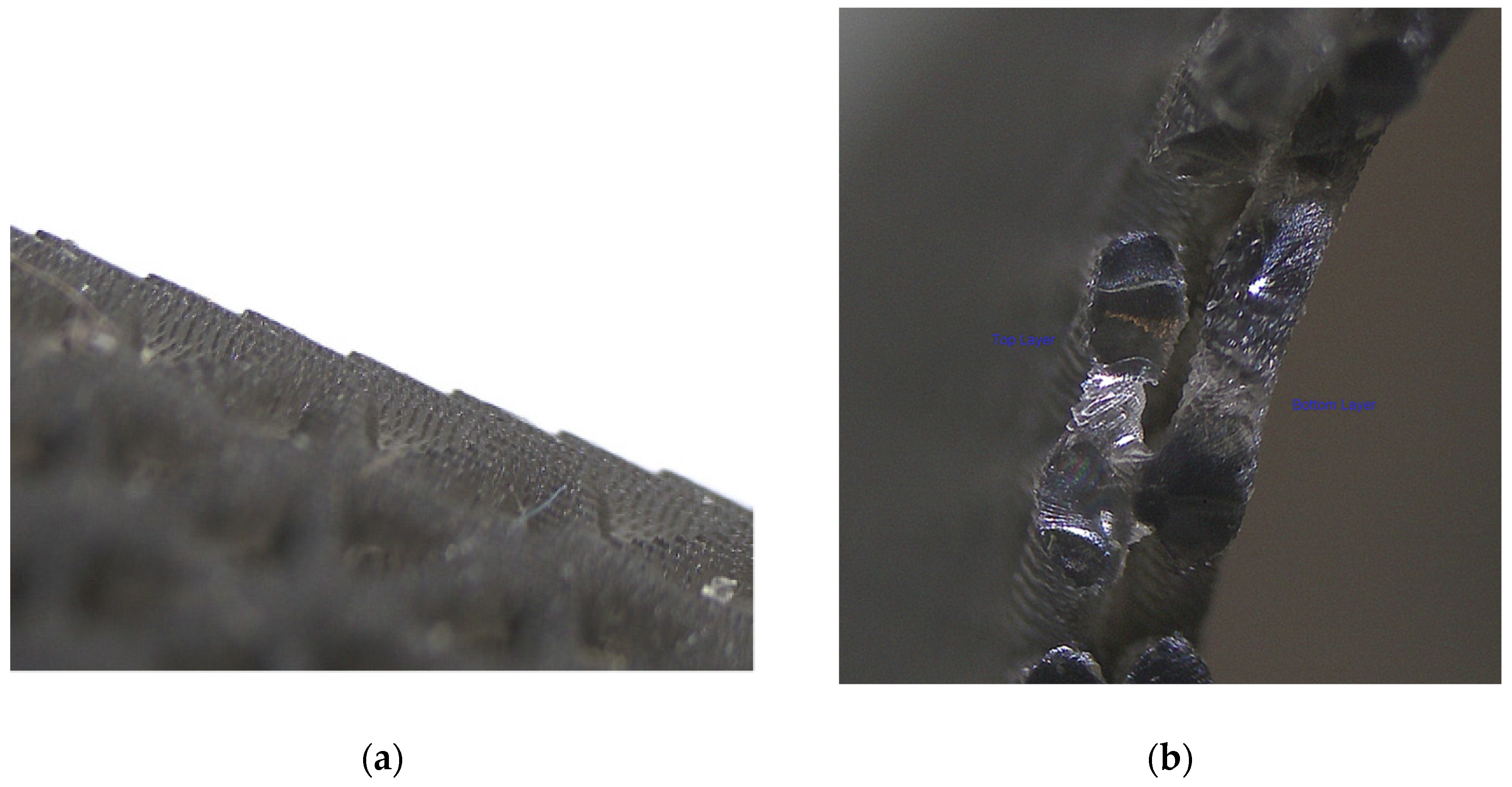
Optical microscopy of the apex of the implant’s curvature revealed a stepped, scale-like micro-topology, consistent with the intended breakup of periodicity from the 70% mesh reduction (Section 2.1), without introducing surface features large enough to further irritate surrounding tissue; these micro-scales later proved beneficial as anchoring sites for the BTO coating (Section 3.2). Cross-sectional imaging confirmed that the bi-layer scaffold architecture was cleanly reproduced, with no underdeveloped material or pore blockage
Figure 3.
(a) Scale edge formation on the apex of the dorsal plate; (b) Cross-section of the Delaunay scaffold.
Figure 3.
(a) Scale edge formation on the apex of the dorsal plate; (b) Cross-section of the Delaunay scaffold.
Crucial to achieving this open bi-layer fidelity was the complete evacuation of unreacted liquid resin during post-processing. Detached in the green state, the internal channels of the Delaunay lattice are highly susceptible to monomer entrapment [7]. Leveraging the hydrophilic nature of the water-soluble resin, agitated water immersion effectively stripped excess surface monomers without degrading the cured core, while targeted high-pressure air jetting cleared lingering resin from the orifices, preventing pore clogging and thermal sintering artefacts commonly encountered in powder-based fusion (PBF) and similar processes [7,21,22]. Subsequent uniform radiation inside a UV post-curing chamber for ~5 minutes on a rotating base completed the polymerisation of the residual monomer chains deep within the structure, maximising the cross-linking density of the Delaunay network to ensure the polymer could endure subsequent thermal cycles during chemical coating without plastic deformation or softening [6,23]. High-magnification cross-sectional examination confirmed that the overlapping strut layers remained fully distinct, maintaining open 0.25mm strut boundaries and unobstructed vertical drainage pathways essential for subsequent liquid coating penetration and tissue vascularisation [8,24].
3.2. Chemical Characterisation of the BTO Coating
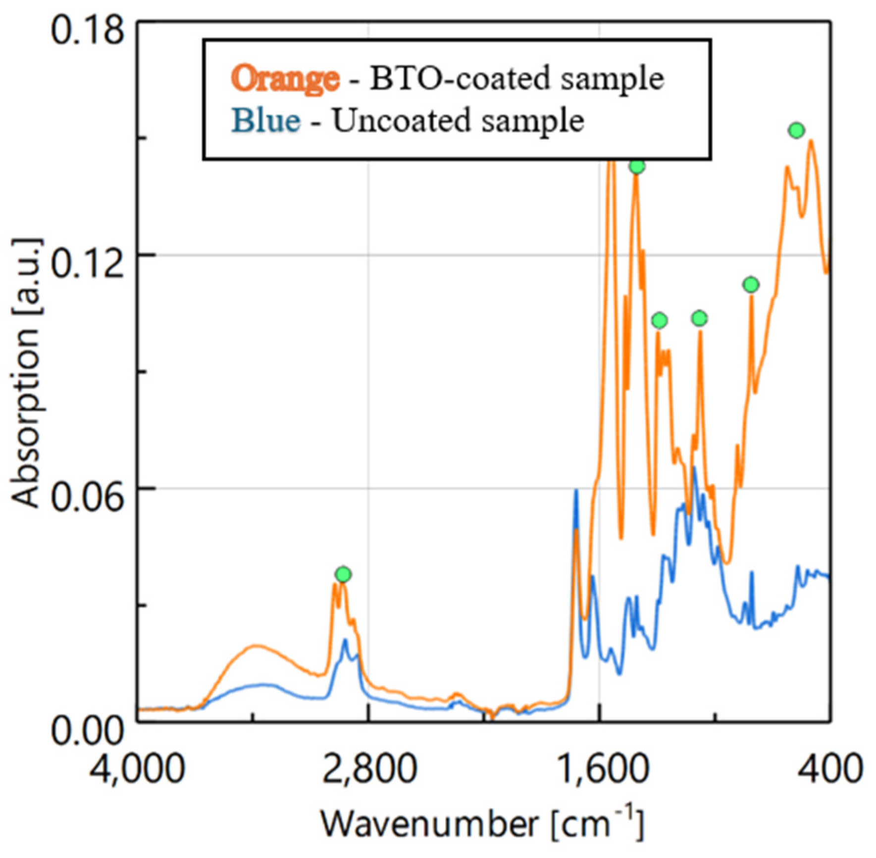
Fourier Transform Infrared (FTIR) spectroscopy was performed to map the molecular transformation from the starting reagents into the finalised BTO solution and to verify complete chemical conversion prior to deposition. The BTO solution was analysed against each individual precursor (barium and titanium). Both the barium precursor and the BTO solution share a characteristic aliphatic C-H stretch at ~2900 cm-1. Below 1800 cm-1, the weak carboxylate coordination band of the barium precursor evolves into a prominent carbonyl (C=O) peak in the BTO mixture, indicating the release of free, uncoordinated organic acid residues, while carbonate (CO32-) bands at ~1300 cm-1 and ~900 cm-1 confirm the formation of transient BaCO3 intermediate phases. Against the titanium precursor, the BTO solution shows a drastic compression in relative intensity of the alkoxide butoxy (-OC4H9) carrier bands between 1500 and 1000 cm-1, confirming that the isolated titanium centres successfully coordinated and condensed into the inorganic network, while the emergence of a lattice absorption band near ~500 cm-1 corresponds to condensed Ti-O and Ti-O6 bond stretching. A consolidated peak assignment is given in Table 2.
Figure 4.
FTIR analysis of the BTO-submerged cured polymeric resin scaffold with an unsubmerged variant.
Figure 4.
FTIR analysis of the BTO-submerged cured polymeric resin scaffold with an unsubmerged variant.
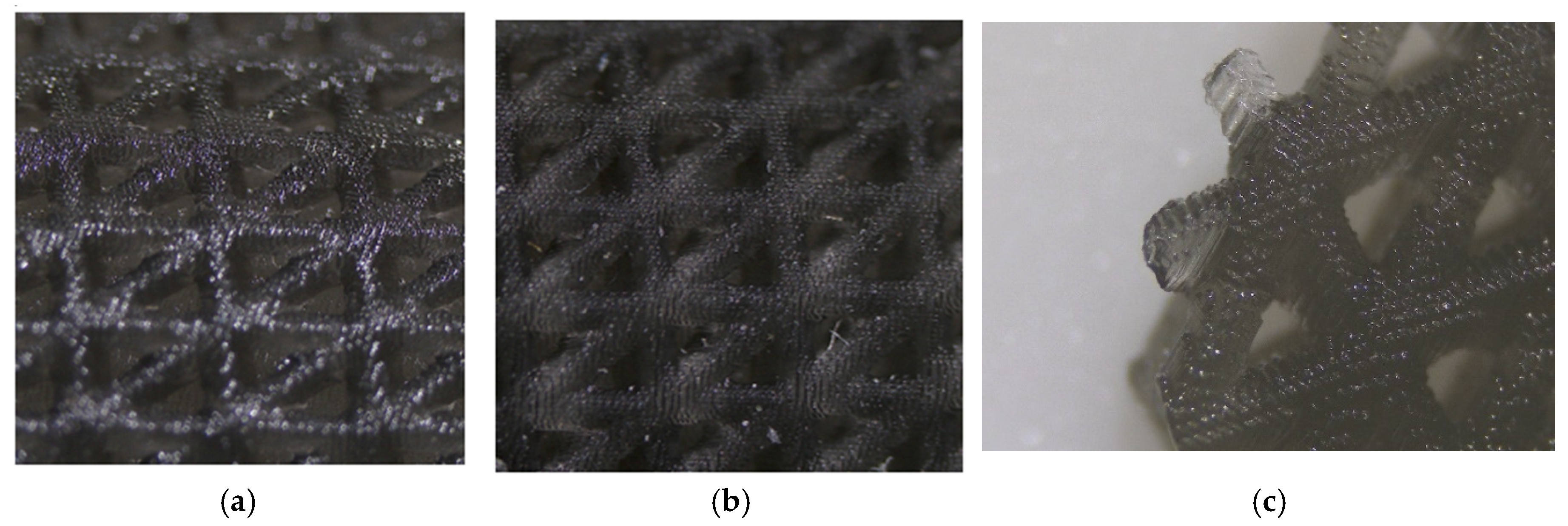
To verify the physical presence of the deposited material and assess the morphological changes induced by the coating cycle detailed above, the consolidated sample was brought for microscopic optical imaging. The primary objective of this procedure was to identify clear surface indicators that would confirm the presence of the inorganic BTO—signifying successful adhesion to the polymer scaffold base—while ensuring that the Delaunay micro-topology remained uncompromised. The coated sample was positioned under a high-resolution Optika microscope.
Under observation, the captured visual data provides clear proof of a successful surface coat and functionalisation. As shown above in Figure 5c, the primary indicator of a complete coating is a distinct, bright sheen that uniformly reflects across the top edges of the structural struts. While standard, uncoated water-soluble resin exhibits a diffuse, flat matte finish, the BTO-coated sample’s surfaces interact with the microscope’s light source to produce a highly reflective top layer. This confirms the formation of a dense, well-packed inorganic boundary layer created as the BTO solution was baked in during the sequential thermal treatment cycles. The purpose of inspecting the cross-sectional boundaries in a strut is to confirm the interface between the core polymeric material and the transparent overlaying coat. Figure 4.5 demonstrates that the 0.25-millimetre strut dimensions and internal cell pathways remain completely open and clear of blockages or film trappings. This supports the previously-discussed approach to thermal treatment—cyclic, 15-minute thermal consolidation phases—as having successfully solidified the BTO solution into a thin, uniform coating that envelops the contours of the struts, rather than filling in the pores between the micro-geometries, which are required to remain free and unclogged. This characterisation has provided the final geometric confirmation that the multi-stage coating procedures created a continuous, low-profile BTO interface while preserving the micro-topology of the original design.
Figure 5.
(a) Microscopic image of the Delaunay mesh on the BTO coated resin sample; (b) a non-coated sample; (c) Close-up image of the cross-section of the Delaunay mesh on the BTO coated resin sample.
Figure 5.
(a) Microscopic image of the Delaunay mesh on the BTO coated resin sample; (b) a non-coated sample; (c) Close-up image of the cross-section of the Delaunay mesh on the BTO coated resin sample.
3.3. Mechanical and Piezoelectric Performance
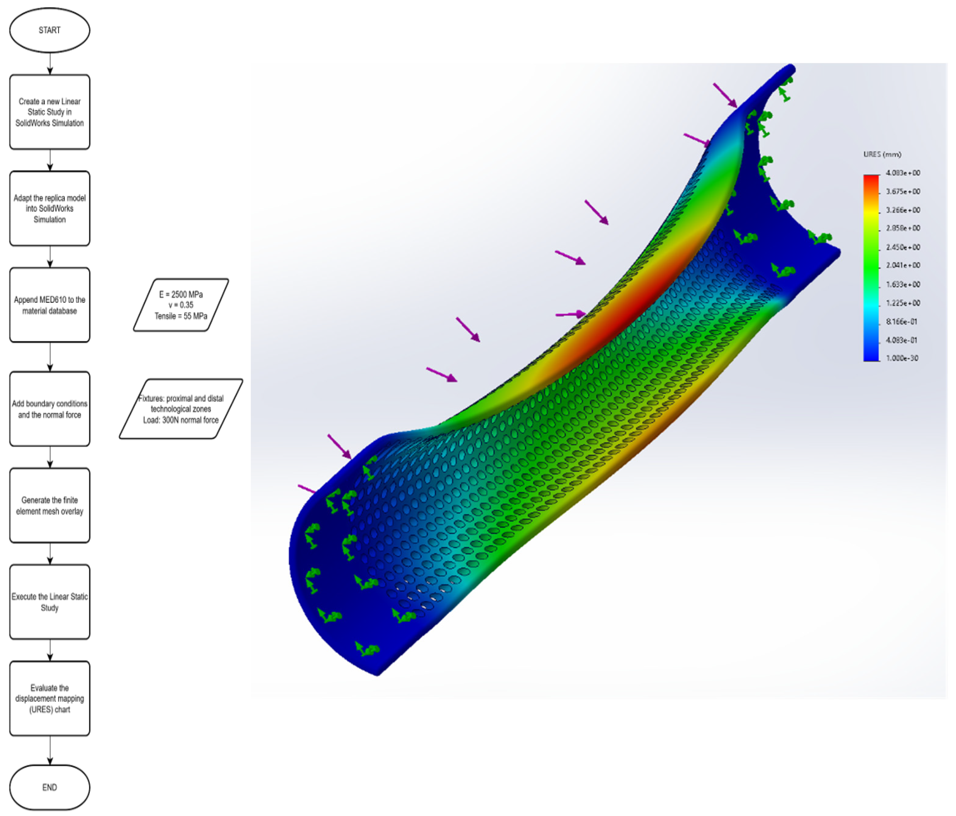
The FEA replica model (MED610 properties, 72.6% porosity) subjected to a 300 N normal force at the plate apex produced a smooth, controlled displacement gradient, transitioning from the rigid, anchored technological zones toward a peak elastic deflection (URES) of 4.083 mm at the centre of the span. No localised buckling or material collapse was observed, despite the more than 70% volumetric material reduction of the active zone, supporting the mechanical viability of the porous dorsal-plate geometry under a load representative of the average fracture force of the intact bone. The process flow diagram and the resulting interface may be seen below in Figure 6:
Figure 6.
(Left) Process flow diagram followed for generating the analysis; (Right) FEA analysis of the universal resulting displacement as a result of the normal force.
Figure 6.
(Left) Process flow diagram followed for generating the analysis; (Right) FEA analysis of the universal resulting displacement as a result of the normal force.
Under periodic compressive loading of the BTO-coated implant, two force regimes produced clearly distinguishable open-circuit voltage responses (Figure 7). At ~1 N (approximately 0-5 s of the recorded trace), the signal oscillated with peak amplitudes in the ~0.3-0.4 V range; when the applied force was increased to ~2 N (approximately 10-15 s), the peak amplitude rose to ~0.5-0.7 V.
Figure 7.
Time-dependent voltage response of the BaTiO3-coated implant under periodic mechanical excitation at 1 N and 2 N.
Figure 7.
Time-dependent voltage response of the BaTiO3-coated implant under periodic mechanical excitation at 1 N and 2 N.
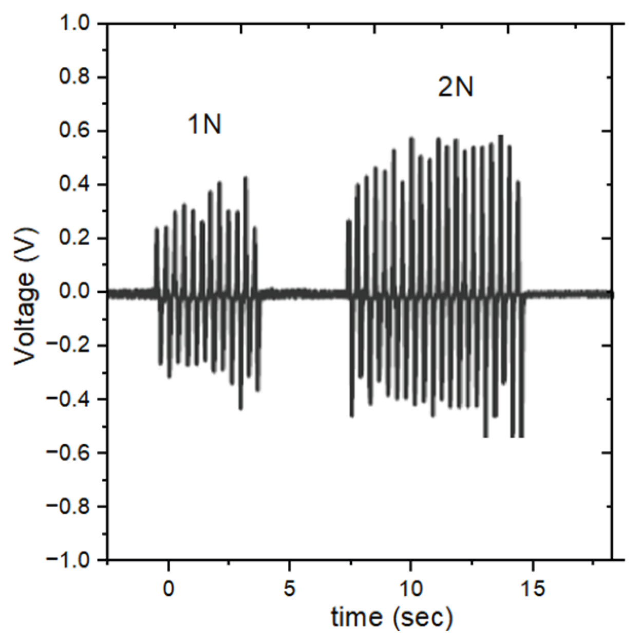
The signal was alternating (AC) in nature, with each compression-release cycle generating a positive and negative voltage peak consistent with polarisation reversal in the BTO layer. The stable, repeatable waveform and low signal noise indicated good mechanical coupling between the polymer matrix and the piezoelectric coating, and confirmed a clear, monotonic dependence of the generated voltage on the applied mechanical force.
4. Conclusions
This study demonstrates that a 4D smart, piezoelectric fifth-metacarpal implant can be designed and manufactured using accessible, consumer-grade stereolithography. Reformulating a curved dorsal-plate base with a 70%-reduced Delaunay lattice achieved a 73.6% porosity and a quasi-isotropic, bending-dominated mechanical response, validated by finite element analysis to withstand a representative 300 N fracture load with a peak deflection of 4.083 mm and no structural collapse. Prints reproduced the CAD geometry with 98.75% average dimensional accuracy. A barium titanate coating, applied via a three-cycle, low-temperature submersion process, was shown by FTIR and optical microscopy to form a chemically bonded, pore-preserving layer, and the coated implant generated a repeatable, force-dependent open-circuit voltage of 0.3-0.7 V under cyclic compressive loading, confirming genuine piezoelectric functionality. Together, these results support the feasibility of an accessible, additively manufactured route to active, self-stimulating orthopaedic hardware for hand trauma applications, while highlighting biocompatible-resin substitution and physiologically representative mechanical testing as the key next steps toward clinical translation.
Author Contributions
Conceptualisation, E.G. Tuns and M. Nasui; methodology, E.G. Tuns and M. Nasui; software, E.G. Tuns; validation, E.G. Tuns, M. Nasui and R. Pacurar; formal analysis, E.G. Tuns and M. Nasui; investigation, E.G. Tuns and M. Nasui; resources, E.G. Tuns and M. Nasui; data curation, E.G. Tuns and M. Nasui; writing—original draft preparation, E.G. Tuns; writing—review and editing, E.G. Tuns and M. Nasui; visualisation, E.G. Tuns and M. Nasui; supervision, R. Pacurar; project administration, R. Pacurar; funding acquisition, R. Pacurar. All authors have read and agreed to the published version of the manuscript.
Funding
This research received no external funding.
Data Availability Statement
The original contributions presented in this study are included in the article/supplementary material. Further inquiries can be directed to the corresponding author(s).
Acknowledgments
This research was supported by the ERASMUS+ Partnerships for cooperation and exchanges of practices (KA220) -“Biomedical Innovations through Digital Transformation of Additive Technologies and Knowledge Exchange—BIOMEDIX”—Project No. 2024-1-LV01-KA220-HED-000255929.
Conflicts of Interest
The authors declare no conflicts of interest.
Abbreviations
The following abbreviations are used in this manuscript:
| BTO | Barium Titanate |
| CCS | Cannulated Compression Screw |
| FEA | Finite Element Analysis |
| 4D | Four-Dimensional |
| CAD | Computer-Aided Design |
| FTIR | Fourier-Transform Infrared |
References
- Nemirov, D.; Kasper, A. A.; Sherman, M.; Siddiqui, H.; Ilyas, A. M.; Hozack, B. ‘Metacarpal Fracture Trends in Treatment: A Matched Cohort Analysis of 1022 Patients’. Arch. Bone Jt. Surg. 2025, vol. 13(no. 8), 489–496. [Google Scholar] [CrossRef] [PubMed]
- Deuschl, J.; Alfort, H.; Wilcke, M. ‘The Epidemiology of Metacarpal Fractures: A Descriptive Study Based on 18,802 Fractures From the Swedish Fracture Register’. J. Hand Surg. Glob. Online 2025, vol. 7(no. 4), 100725. [Google Scholar] [CrossRef] [PubMed]
- Sohn, R. C.; Jahng, K. H.; Curtiss, S. B.; Szabo, R. M. ‘Comparison of Metacarpal Plating Methods’. J. Hand Surg. 2008, vol. 33(no. 3), 316–321. [Google Scholar] [CrossRef] [PubMed]
- Matzon, J. L.; Kenniston, J.; Beredjiklian, P. K. ‘Hardware-Related Complications After Dorsal Plating for Displaced Distal Radius Fractures’. Orthopedics 2014, vol. 37(no. 11). [Google Scholar] [CrossRef] [PubMed]
- Nicoletti, D.; Knipe, H. ‘Stress shielding after fracture fixation’. In Radiopaedia.org, Radiopaedia.org; 2023. [Google Scholar] [CrossRef]
- Bukhari, S. M. Z. S.; Bukhari, M. A.; Hossain, M. ‘Vat Photopolymerization of Smart Polymers for Biomedical Applications’. ACS Appl. Polym. Mater. 2025, vol. 7(no. 18), 12117–12144. [Google Scholar] [CrossRef] [PubMed]
- ‘Design for Additive Manufacturing with PolyJet’. Stratasys. Available online: https://d2pye4zfc3qqup.cloudfront.net/wp-content/uploads/2020/08/18145504/Best-Practice-Design-for-Additive-Manufacturing-with-PolyJet.pdf.
- Zenobi, E.; et al. ‘Tailoring the Microarchitectures of 3D Printed Bone-like Scaffolds for Tissue Engineering Applications’. Bioengineering 2023, vol. 10(no. 5), 567. [Google Scholar] [CrossRef] [PubMed]
- Sahoo, R.; et al. ‘Designing of porous scaffolds for tissue engineering and regenerative medicine’. J. Mater. Chem. B 2026, vol. 14(no. 9), 2733–2773. [Google Scholar] [CrossRef] [PubMed]
- Shyeed, Md. A.; Ferdaus, J.; Hossain, M. F.; Hossain, M. A.; Hossain, K. R. ‘Polymer-Based Smart Material in 4D Printing Applications’. Smart Wearable Technol. 2025, vol. 2, A2. [Google Scholar] [CrossRef]
- Nasui, M.; et al. ‘New approach for oriented BaTiO3 thin films with piezoelectric properties through chemical synthesis’. J. Alloys Compd. 2025, vol. 1036, 182008. [Google Scholar] [CrossRef]
- Zhou, Z.; Qian, D.; Minary-Jolandan, M. ‘Molecular Mechanism of Polarization and Piezoelectric Effect in Super-Twisted Collagen’. ACS Biomater. Sci. Eng. 2016, vol. 2(no. 6), 929–936. [Google Scholar] [CrossRef] [PubMed]
- Jacob, J.; More, N.; Kalia, K.; Kapusetti, G. ‘Piezoelectric smart biomaterials for bone and cartilage tissue engineering’. Inflamm. Regen. 2018, vol. 38(no. 1), 2. [Google Scholar] [CrossRef] [PubMed]
- Ganeson, K.; May, C. Tan Xue; Abdullah, A. A. A.; Ramakrishna, S.; Vigneswari, S. ‘Advantages and Prospective Implications of Smart Materials in Tissue Engineering: Piezoelectric, Shape Memory, and Hydrogels’. Pharmaceutics 2023, vol. 15(no. 9), 2356. [Google Scholar] [CrossRef] [PubMed]
- AO Foundation. ‘Headless Compression Screw Insertion’, AO Surgery Reference: Adult Trauma, Basic Technique. Available online: https://surgeryreference.aofoundation.org/orthopedic-trauma/adult-trauma/basic-technique/headless-compression-screw (accessed on Jun. 09 2026).
- Moura Neto, F. N. D.; et al. ‘Castor polyurethane used as osteosynthesis plates: microstructural and thermal analysis’. Polímeros 2019, vol. 29(no. 2), e2019029. [Google Scholar] [CrossRef]
- Zhang, J.; Liu, C.; Li, J.; Yu, T.; Ruan, J.; Yang, F. ‘Advanced Piezoelectric Materials, Devices, and Systems for Orthopedic Medicine’. Adv. Sci. 2025, vol. 12(no. 3), 2410400. [Google Scholar] [CrossRef] [PubMed]
- Carter; Popowski, K.; Cheng, K.; Greenbaum, A.; Ligler, F. S.; Moatti, A. ‘Enhancement of Bone Regeneration Through the Converse Piezoelectric Effect, A Novel Approach for Applying Mechanical Stimulation’. Bioelectricity 2021, vol. 3(no. 4), 255–271. [Google Scholar] [CrossRef] [PubMed]
- Mueller, J.; Matlack, K. H.; Shea, K.; Daraio, C. ‘Energy Absorption Properties of Periodic and Stochastic 3D Lattice Materials’. Adv. Theory Simul. 2019, vol. 2(no. 10), 1900081. [Google Scholar] [CrossRef]
- Yamada, S.; Suzuki, H.; Sawada, K.; Okada, S.; Nishimura, A.; Todoh, M. ‘Novel strut-based stochastic lattice biomimetically designed based on the structural and mechanical characteristics of cancellous bone’. Mater. Des. 2025, vol. 251, 113657. [Google Scholar] [CrossRef]
- Rott, S.; Ladewig, A.; Friedberger, K.; Casper, J.; Full, M.; Schleifenbaum, J. H. ‘Surface roughness in laser powder bed fusion—Interdependency of surface orientation and laser incidence’. Addit. Manuf. 2020, vol. 36, 101437. [Google Scholar] [CrossRef]
- Islam; Rahman, M. Z. ‘Recent advances in additive manufacturing techniques: An in-depth review’. In Comprehensive Materials Processing; Elsevier, 2024; pp. 352–378. [Google Scholar] [CrossRef]
- Dizon, J. R. C.; Espera, A. H.; Chen, Q.; Advincula, R. C. ‘Mechanical characterization of 3D-printed polymers’. Addit. Manuf. 2018, vol. 20, 44–67. [Google Scholar] [CrossRef]
- Wang, C.; et al. ‘3D printing of bone tissue engineering scaffolds’. Bioact. Mater. 2020, vol. 5(no. 1), 82–91. [Google Scholar] [CrossRef] [PubMed]

Table 1.
CAD versus printed dimensions of the technological zone width (A) and Delaunay unit cell length (B) and height (C).
Table 1.
CAD versus printed dimensions of the technological zone width (A) and Delaunay unit cell length (B) and height (C).
| Dimension [mm] | CAD model | Accuracy | |
|---|---|---|---|
| A — technological zone width | 2.586 | ~2.626 | 98.45% |
| B — unit cell length | 1.319 | ~1.292 | 98.10% |
| C — unit cell height | 1.012 | ~1.013 | 99.90% |
Table 2.
Consolidated FTIR molecular bond assignments for the BTO precursor system.
| Peak position [cm-1] | Bond assignment | Vibration type | Associated phase |
|---|---|---|---|
| ~500 | Ti-O / Ti-O6 | Bending / lattice stretch | Crystalline BaTiO3 |
| ~900 | C-O | Out-of-plane bending | Carbonate in residual BaCO3 |
| ~1300 | C-O | Asymmetric stretch | Carbonate intermediate phase |
| ~1400-1500 | COO- / C-H | Carboxylate / alkane bend | Resin-metal ion coordination |
| ~1700 | C=O | Carbonyl stretch | Free organic acid carriers |
| ~3000 | C-H | Aliphatic alkane stretch | Cross-linked polymer backbone |
| >3200 | O-H | H-bonded stretch | Bound water / surface hydroxyls |
Disclaimer/Publisher’s Note: The statements, opinions and data contained in all publications are solely those of the individual author(s) and contributor(s) and not of MDPI and/or the editor(s). MDPI and/or the editor(s) disclaim responsibility for any injury to people or property resulting from any ideas, methods, instructions or products referred to in the content. |
© 2026 by the authors. Licensee MDPI, Basel, Switzerland. This article is an open access article distributed under the terms and conditions of the Creative Commons Attribution (CC BY) license (http://creativecommons.org/licenses/by/4.0/).
Copyright: This open access article is published under a Creative Commons CC BY 4.0 license, which permit the free download, distribution, and reuse, provided that the author and preprint are cited in any reuse.