
Submitted:
15 September 2026
Posted:
16 September 2026
You are already at the latest version
Abstract
With the continuous expansion of the depth and scale of mining, the mined-out area poses a major threat to the safety of mine production, the surrounding environment, and the lives of residents. Because of the potential safety hazards caused by the large-scale collapse of the mined-out area of metal mines, a treatment plan was formulated in combination with the actual geological conditions of the mined-out area under a metal mine in Henan Province. Through the comparative analysis of the treatment scheme, the blasting caving method is preliminarily selected to control the mined-out area. Considering that the roof of the mined-out area of the mine is strong and the area of the mined-out area is large, an optimized blasting caving method—Underground induced caving and roof cutting technique scheme. Considering the influence of geological conditions and surrounding rock, Flac3D was used for numerical simulation calculation, and the design of the Underground induced caving and roof cutting technique scheme and blasting operation was formulated. By canceling the pressure relief skylight project, unnecessary engineering expenditure is avoided, and the investment structure of the project is optimized. Through the on-site blasting practice, the roof of the mined-out area gradually collapses, and the precise damage induction of the roof of the mined-out area is realized. Finally, a stable waste rock overburden is formed, which effectively prevents the occurrence of sudden roof caving and significantly reduces the risk of mine safety production. It provides technical ideas and practical experience for the treatment of mined-out areas under similar geological conditions.
Keywords:
mined-out area
; blasting caving method
; roof cutting
; induced caving
1. Introduction
With the rapid development of the world economy and science and technology, the energy demand is increasing, especially the consumption of mineral energy [1]. However, although the exploitation of mineral resources meets the energy demand, it also brings many environmental and safety problems that cannot be ignored [2]. In the process of mineral exploitation, catastrophic events such as land subsidence, landslides, and air pollution often occur, which have a great impact on the ecological environment and residents ' lives [3]. It is worth noting that among these problems, disasters such as land subsidence and landslides are often directly related to underground mining activities, and the core incentive is the formation of a mined-out area [4]. Once the mined-out area collapses, it may cause serious land subsidence, building damage, and even casualties [5]. Therefore, the exploitation of mineral resources should not only consider the economic benefits, but also need to strengthen the scientific management of mined-out areas, prevent risks, and ensure the safety and sustainable development of mining [6].
Due to the complexity of the space and shape of the mined-out area, the treatment of the mined-out area has become a difficult problem to ensure the safe production of the mine [7]. In recent years, many scholars have done a lot of research on the stability of mined-out areas [8]. The current research methods are classified from the perspective of ground pressure control [9,10]. At present, the main mined-out area treatment methods include blasting caving method, the filling method, the closed isolation method, and the support method [11]. According to the characteristics of large volume and irregular shape of the mined-out area, Xu et al. [12] adopted the scheme of strip chamber blasting and caving method, which well solved the hidden danger problems existing in the super large mined-out area. Miao et al. [13] separated underground coal gangue and used gangue filling technology to realize gangue emission reduction, control surface subsidence, and realize green mining. Zhang et al. [14] used the closed isolation method in the form of a buffer-type wave-blocking wall and a solid wave-blocking wall, which has a certain reference value for the treatment of mined-out areas. Liu et al. [15] adopted the long-wall coal pillar support method, retaining a certain number and width of coal pillars to support the rock strata above and prevent the collapse of the mined-out area.
The above methods provide different solutions for the treatment of mined-out area hazards from the perspective of geological analysis and technical feasibility. However, because of the special working conditions that the mine still has 15 years of service life and the mining depth is increasing year by year, the traditional filling method and supporting technology are faced with double constraints: on the one hand, with the increase of mining depth, the transportation cost of filling materials increases exponentially; on the other hand, the deep high ground stress environment significantly increases the risk of instability of the artificial support structure. The blasting caving method can make the ore in the mined-out area fall evenly by accurately controlling the blasting process, which can fill the mined-out area, realize natural closure or stability, reduce the risk of collapse, and avoid the high cost and long construction period caused by the use of filling materials and supporting equipment [16,17].
Based on this, this paper uses the blasting caving method, from the three angles of geological analysis, technical feasibility, and economic saving, and puts forward the optimized blasting caving method mined-out area treatment scheme: Underground induced caving and roof cutting technique scheme. Through FLAC3D software, the stability of the mined-out area is analyzed, and a reasonable mined-out area treatment scheme is designed. The results show that the Underground induced caving and roof cutting technique scheme proposed in this paper successfully solves the problem of mined-out area, eliminates the hidden danger of large mined-out areas in the mine, and ensures the safe production of the mine. At the same time, because the pressure relief skylight project is cancelled, the project investment is reduced. The scheme not only effectively solves the problem of mined-out area, eliminates the hidden danger of large mined-out area in mines, but also optimizes the engineering investment structure, which provides a strong guarantee for the safe production and long-term operation of mines.
2. Research Methodology
2.1. Blasting Caving Method
Blasting caving method is a kind of underground engineering control technology that artificially creates caving conditions by active blasting [18]. Its core principle is to use high-intensity blasting to pre-destroy the structural integrity of the rock mass and induce the systematic rupture and continuous collapse of the target rock layer under the coupling effect of gravity and blasting power [19]. This method is especially suitable for the field of mined-out area treatment: by arranging reasonable spacing holes in the overlying strata of the mined-out area, the stability of the roof strata is accurately destroyed after detonation, so that the upper roof collapses and fills the mined-out area, thus quickly eliminating safety hazards. The advantage of this technology is that the process is relatively simple, the cost is controllable, and the natural dense filling of the mined-out area can be realized [20].
2.2. Roof Cutting
Roof cutting is the core technology of mining site pressure control in underground hard rock mines [21]. The core mechanism is based on the artificial preset separation surface. Through blasting or hydraulic fracturing, a continuous weakening zone is constructed in the roof strata, and the complete roof is divided into structures that can move independently, to remove the mechanical connection between the mined-out area and the production area [22]. The technology relies on the principle of rock fracture mechanics. When the working face advances to the weakening zone, the gravity load of the roof is transferred to the side of the mined-out area through the weakening surface, which promotes the shear slip or tensile fracture of the roof surface and realizes the directional release of the roof stress field.
2.3. Induced Caving
Roof caving is the key technology to actively control the stability of the mined-out area roof in underground mining engineering [23]. It refers to the artificial intervention to induce the roof above the mined-out area to collapse in a predetermined mode, to eliminate the hidden danger of the mined-out area, and optimize the distribution of ground pressure. The core principle is to systematically weaken the self-bearing capacity of the rock mass. When the working face advances to a specific stage, the roof strata form stress concentration due to the increase in the exposed area. At this time, physical or chemical means (mainly blasting method) are used to create penetrating cracks in the roof and destroy the continuity of the roof structure [24]. When the strength of the rock mass falls below the critical value of the gravity load, shear failure or tensile fracture occurs along the weakening surface of the roof, and controllable caving is realized [25].
3. Remediation Technology
3.1. Overview of Mined-Out Areas
W Metal Mine is located in Henan Province, with a design scale of 650000 t/a. The room-pillar method was adopted in the initial stage of the mine, and then gradually converted to the sublevel caving method without a sill pillar. This method should have filled the mined-out area by caving the overlying surrounding rock to release the ground pressure [26]. However, during the implementation of the mine, it was found that due to the abnormal firmness and integrity of the roof rock mass of the deposit, it failed to form natural caving as expected after mining. The maximum exposed area of the mine mined-out area is 19218 m2, the volume is 1.5 million m3, and the vertical distribution is between −40m and −5m.
Through on-site exploration, the location, scale, exposed area, connectivity, and pillar situation of the mined-out area in this part are counted. The statistical table of the mined-out area is shown in Table 1.
Table 1 presents detailed statistics of the key parameters of the mined-out area formed by the room-pillar method and the non-pillar sublevel caving method in the three mining levels of −5m, −20m, and −40m in the W metal mine. At present, the total volume of the underground mined-out area in the mining area is 964561 m3, of which the volume of the mined-out area in the sublevel caving method without sill pillar is 626610 m3, and the volume of the mined-out area accounts for 65 % of the volume of the whole mined-out area. The mined-out area volume of room-pillar method is 337951 m3.
The overall characteristics are as follows: the mined-out area of room-pillar method reaches the maximum span of 175 m at the level of −5m, and the exposed area at the level of −20m reaches 19218 m2 (the extreme value of the whole mine). The area of the pillar increases with the increase of depth, but the mined-out area is not connected. The continuously exposed area of 253385 m3 with the largest volume is formed in the mined-out area of sublevel caving method without sill pillar at the level of −5m. All the layered mined-out areas are completely connected, and no pillars are retained.
It is worth noting that the mined-out area of sublevel caving method without sill pillar at the −5m level carries a rock burst risk due to its exceptionally large volume and full connectivity. The mined-out area of the −20m horizontal room-pillar method has the largest exposed area, and the proportion of pillar support is less than 10%, which may lead to roof collapse. The span of the mined-out area of the −40m horizontal room-pillar method is sharply reduced to 65m, indicating that the difficulty of deep mining is significantly increased.
3.2. Primary Selection of Governance Scheme
Because of the safety hazards in the mined-out area of the mine, the filling method, the closed isolation method, and the support method are used to deal with the mined-out area [27,28]. Although the safety risks can be alleviated to a certain extent, the long-term hidden dangers caused by the mined-out area cannot be fundamentally solved. Especially for the mine, the above three methods have some practical difficulties and limitations, resulting in the inability to eliminate security risks, and may even bring new problems. Filling mined-out area refers to the use of tailings, filling materials, etc., to fill the mined-out area to prevent its continued collapse and ensure mine safety [29]. Although the filling method is theoretically feasible, it faces the problems of high cost, long construction period, and isolation [30]. Tailings filling requires a large amount of materials, which will lead to an increase in production costs. At the same time, it is difficult to isolate the underground mined-out area from the production section, which affects the smooth operation. Considering that the mining area still has 15 years of service life, this method cannot guarantee economic benefits and production progress, so it is not suitable for long-term development. The use of the closed isolation method cannot effectively avoid problems such as collapse or water gushing [31]. At the same time, closed isolation requires a large number of supporting facilities and projects, which leads to the extension of the construction period and an increase in cost. With the deepening of mining depth, the effect may not be sustainable, so the potential safety hazards cannot be fundamentally solved. The supporting method is to stabilize the mined-out area by setting supporting points and supporting facilities [32]. In theory, it can prevent collapse and affect production, but it faces multiple challenges in the mine. First of all, the area of the underground mined-out area reaches 82525 m2, and the volume reaches 964561 m3. It is difficult to arrange the support, and the effect is difficult to guarantee. Secondly, the −5m horizontal pillar has collapsed, resulting in the failure of the support system and the inability to provide effective support. Furthermore, due to the regional unevenness of the mined-out area, the support measures are difficult to implement widely. Therefore, the support method is difficult to fundamentally solve the security problem, and may aggravate the risk.
Compared with the above three methods, the blasting caving method has obvious advantages and can effectively overcome these limitations. Firstly, the blasting caving method makes the ore in the mined-out area fall naturally and evenly by accurately controlling the blasting process, which reduces the instability and high cost caused by support and filling [33]. Secondly, blasting caving can fill the mined-out area more thoroughly, avoiding the problem of isolation and support. At the same time, it will not require a lot of materials and time as the filling method, saving the production cost and construction period [34]. In addition, the blasting caving method is particularly effective in dealing with large-area mined-out areas. Through the accumulation of ore after caving, the natural “self-sealing” or stabilization of mined-out areas can be achieved, thereby reducing the risk of collapse [35]. Therefore, the blasting caving method can not only solve the problems of the above methods in economy, construction period, and support effect, but also ensure the safety of the mining area in a long period, especially for the long-term operation of the mine and the gradual increase of mining depth. In summary, as a comprehensive, safe, and cost-effective treatment method, the blasting caving method is an effective method to solve the hidden danger of mined-out area safety in this mine.
According to the field investigation and research analysis, under the current conditions, the following three feasible treatment schemes are proposed for the treatment of the mined-out area:
- Induced roof caving to form a caved rock coverage layer for mined-out area remediation;
The pressure relief channel is constructed by opening a “skylight” on the roof of the mined-out area, and the waste rock overburden is constructed for the thick area of the lower ore body. The blasting technology is used to break the roof to form a supporting structure, and the connection path between the mined-out area and the skylight is synchronously connected. The double-action mechanism of suppressing the roof caving impact and the energy release of the skylight channel is suppressed by the overburden load, and finally, the systematic elimination of the safety hazards in the super-large mined-out area is realized.
- 2.
- Underground roof cutting induces overall caving to treat the mined-out area;
Using the existing engineering conditions, a certain length and range of cutting grooves are formed by underground deep hole blasting, which induces the instability and caving of the roof above the mined-out area under the action of gravity, and eliminates the potential safety hazards in the large mined-out area.
- 3.
- Surface-based ring-cutting induced caving for mined-out area remediation;
The roof rock of the mined-out area is mainly gneiss, the rock mass is stable, and the mined-out area is in a relatively stable state. By using pre-splitting blasting technology, a cutting groove with a certain length and range is formed along the boundary of the mined-out area on the selected surface, which induces the overall roof caving directly above the mined-out area, to eliminate the potential safety hazard of the extra-large mined-out area.
3.3. Comparison of Mined-Out Area Treatment Schemes
3.3.1. Comparison of the Advantages and Disadvantages of Each Scheme
The advantages and disadvantages of the above three mined-out area treatment schemes are shown in Table 2.
3.3.2. Engineering Quantity Comparison
- Induced roof caving to form a caved rock coverage layer for mined-out area remediation;
The direct investment part of the project: the skylight project is 5.222 million yuan, and the induced caving project is 3.255 million yuan, a total of 8.477 million yuan, and the total amount of roof caving is expected to be 69 tons.
- Underground roof cutting induces overall caving to treat the mined-out area;
The direct investment part of the project: the skylight project is 2.892 million yuan, the roof cutting project is 4.306 million yuan, a total of 7.198 million yuan, and the total amount of roof cutting is expected to be 74.6 t.
- Surface-based ring-cutting induced caving for mined-out area remediation;
The direct investment part of the project: 2.892 million yuan of skylight project, 6.208 million yuan of surface pre-splitting project, a total of 9.293 million yuan, and a total of 34.1 tons of roof cutting dosage is expected.
3.3.3. Solution Selection
At present, the method of induced roof caving to form a caved rock coverage layer for mined-out area remediation is a relatively mature mined-out area treatment technology, which is widely used in large-scale mined-out area treatment in China [36]. The method of underground roof cutting induced overall caving to treat mined-out area and the method of surface annular cutting and caving to deal with mined-out area are technically feasible, but there are few cases in practice, and the method of underground roof cutting induced overall caving to treat mined-out area has a large amount of blasting charge. To reduce the harm of blasting vibration to surrounding villages, it is necessary to divide small blasting into several times, which has a certain impact on the construction progress of subsequent projects. The Surface-based ring-cutting induced caving for the mined-out area remediation method must take measures to reduce the harmful effects of blasting on the surface, resulting in a large cost and a large surface occupation site [37].
Considering the technical reliability, economic rationality, and the difficulty of implementation, it is recommended to use the induced roof caving to form a caved rock coverage layer for mined-out area remediation. However, the method of induced roof caving to form a caved rock coverage layer for mined-out area remediation will lead to the problem of a large amount of skylight engineering. Moreover, due to the large area of mined-out area, it is difficult for waste rock buffer overburden to meet the thickness of overburden completely isolated from mined-out area and stope channel, and it is impossible to completely eradicate the major harm and influence caused by shock wave caused by sudden roof caving, which leads to the increase of the possibility of surface subsidence and the further increase of uncertain factors.
Because of the objective factor that the mined-out area of the mine is large, it is proposed to adopt the Underground induced caving and roof cutting technique scheme, which is to combine the scheme of underground roof cutting induced overall caving, and induced caving roof forming overburden to deal with the mined-out area treatment mined-out area. The purpose is to increase a small amount of roof cutting engineering to induce roof instability and caving. On this basis, the pressure relief skylight is cancelled, the project investment is reduced, and the thickness of the overburden formed by the mined-out area is increased, and the possibility of sudden roof caving is completely eradicated.
3.4. Mined-Out Area Stability Analysis
To assess the stability of mined-out areas following underground induced caving, a numerical simulation was conducted using Flac3D. The stability of the surrounding rock in the mined-out area was analyzed after uniform induced caving of 12 meters, and the calculation results are shown in Figure 1.
It can be concluded from Fig.1 that when the induced caving range extends upward to 12 m, the tensile stress concentration area appears on the roof of the mined-out area, and the roof will have serious tensile failure, which may lead to a certain scale of roof fall. The tensile stress value in most areas is below 2.0 MPa.
It is calculated that when the induced caving height is 20m, the plastic failure zone is more than half of the roof area, and the plastic failure zone appears in the bearing area, and the possibility of large-scale instability of the roof in the mined-out area is high. When the caving height reaches 30 m, in addition to the center of the roof, the main bearing areas at both ends have a wide range of plastic damage, and the roof of the mined-out area is in fact in a completely large-scale instability state. On the whole, when the roof is induced to cave to 12m, the maximum tensile stress zone in the local area of the roof exceeds the tensile strength, excessive settlement begins to occur, and a small range of plastic failure zone appears. It is expected that the roof will have a certain range of instability, but the possibility of overall large-scale instability is general. With the increase of induced caving height, the tensile stress value, settlement value, and plastic zone range are increasing. When the roof is caving to 20m, the plastic failure zone exceeds half of the roof area, and the tensile stress disturbance zone has penetrated the bearing zone at both ends, so it is more likely that the roof of the mined-out area will be unstable in a large range. Therefore, the higher the induced caving height is, the better the roof failure effect is, and the higher the possibility of overall roof instability is. When the caving height is above 20 m, it is expected that the roof may be damaged over a large range.
3.5. Brief Description of the Underground Induced Caving and Roof Cutting Technique Scheme
The Underground induced caving and roof cutting technique scheme is mainly to deal with the mined-out area distributed vertically between −40m and −5m, and to form a waste rock covering layer of more than 20m for the lower stope. The induced caving projects and roof cutting projects are mainly arranged in the stress concentration area around the roof of the mined-out area. The integrity of the rock mass is destroyed by deep hole blasting, which induces the instability and caving of the roof and eliminates the hidden danger of the mined-out area.
The main project of this scheme consists of six parts, including three parts of induced caving project: the southeast induced caving project, the northeast induced caving project and the western induced caving project; there are three parts of the roof cutting project: the southeast roof cutting project, the northeast roof cutting project and the west roof cutting project. The plane position of each project is shown in Figure 2. Among them, red is the roof caving project and blue is the induced caving project.
The roof cutting project is mainly based on the induced caving project, further cutting and destroying the roof, and inducing the part to fall first. A row of upward fan-shaped deep holes is arranged above the chamber. The hole depth is 25~64 m, and the hole bottom distance is less than 4.8 m. Figure 3 is a three-dimensional map of the induced caving and roof cutting blast holes generated in 3Dmine software.
The MD-80 A down-the-hole drilling rig is used in the induced caving project. The diameter of the borehole is φ110mm, and the depth of the borehole is 46~66m. The fan-shaped holes are arranged to provide rock cover for the underground. The hole bottom distance is 5.0~5.6m, and the row spacing is 4.0m.
3.6. Design of Blasting Schemes
3.6.1. Blasting Plan
The underground engineering of this scheme is divided into three parts: southeast engineering, northeast engineering, and western engineering. As shown in Table 3, the total number of blast holes is 340, the total charge holes is 284, the total length of blast holes is 15071.2m, the total length is 7674.4m, and the total charge quantity is 55631.3kg. The main material consumption is shown in Table 4. A total of 55.6 tons of emulsion explosive, 1361 detonators, 28500m non-electric detonators, 4 digital electronic detonators, and 9209m detonating cords are required.
According to the field blasting vibration test report, the maximum segment charge is not more than 500 kg. The schematic diagram of the blasthole detonation connection is shown in Figure 4.
The hole-by-hole blasting technology is adopted. Each row of fan-shaped holes or each group of blast holes is detonated by detonating tube detonators. The detonating cord is installed in the hole. The double non-electric detonating tube detonator is used to detonate the explosive charge in the hole, and 1~2 blast holes are detonated in sections. Detonation network: a compound initiation network is used between the initiation point and each chamber, and two sets of non-electric detonating tube initiation systems are used. The underground initiation point is initiated by digital electronic detonators. Six parts of the project are expected to be completed within 10~20 seconds.
3.6.2. Blast Hole Layout
The rock of the mine roof is dense and hard, and the smaller roof cutting angle has little effect on the extrusion friction of the roof on both sides of the slit [38]. The roof can still be regarded as a whole, and the extrusion friction between the roofs is greater than the sliding force of the roof, which makes the roof difficult to collapse. A larger roof cutting angle will lead to complete collapse of the mined-out area, and there is a potential safety hazard. When the height of the mined-out area is > 1m, the roof cutting angle cannot exceed 15 ° [39]. To ensure that the roof of the mined-out area can fall smoothly after roof cutting, the final roof cutting angle is 10 °. The dip angle of induced caving blast holes is 5°, the diameter of the blasting hole is φ120 mm, and the bottom distance of the hole is 2.5~4.5 m. It mainly forms a covering layer for the mined-out area, and adds a small amount of roof cutting engineering to induce roof instability and caving, to protect the safety of underground equipment and facilities.
3.6.3. Subsubsection
The coupling charge is used in the design, and the charge density is 0.95~1.0g/cm3. First, the bottom hole is sealed, and the charge is required to start at the bottom of the hole, and the gun mud with a length of not less than 5m is filled [40,41]. On-site measures such as adding an appropriate amount of diesel oil to the powdery emulsion explosive and increasing the pressure of the air compressor are used to increase the viscosity of the explosive. Practice has proved that this measure can effectively reduce the return powder of the explosive and increase the utilization rate of the explosive. Figure 5 shows the scene of workers charging into the scene.
4. Remediation Technology
The successful detonation of explosives marks the effective control of hidden dangers in the mined-out area. After the implementation of blasting, the surrounding rock in the upper part of the mined-out area began to collapse gradually, forming a conical collapse pit with a depth of about 30 meters and a radius of about 80 meters, as shown in Figure 6. The formation process of the collapse pit has certain coherence and regularity, which indicates that the blasting operation accurately controls the expansion of the collapse area and ensures that the collapse area completely covers the mined-out area, thus eliminating the potential safety hazards.
After the successful completion of the detonation, with the gradual collapse of the surrounding rock, the collapse area gradually expands to the surface. The shape and scope of the collapse pit provide clear feedback for engineering and technical personnel, which proves the feasibility and effectiveness of the blasting caving method in practical application. After the successful blasting, the hidden danger space of 964561 m3 in the mined-out area has been effectively treated, which ensures the safety and stability of mine production.
In addition, the successful implementation of the underground induced caving and roof cutting technique scheme also shows that the technology can effectively control the stability of the large-scale mined-out area in the mine and reduce the risk of secondary disasters that may be brought by the traditional method. By accurately calculating the blasting parameters and scientifically arranging the detonation sequence and time, it is ensured that the surrounding rock movement during the collapse process is in line with expectations and does not adversely affect the surrounding environment and facilities.
5. Conclusions
The underground induced caving and roof cutting technique scheme has performed well in practical application, which has successfully solved the safety hazards in the mined-out area and ensured the safe production of the mine. Through on-site blasting practice, the roof of the mined-out area gradually collapsed, and finally, a stable waste rock overburden was formed, which effectively prevented the occurrence of sudden roof caving and significantly reduced the risk of mine safety production.
Compared with the traditional single method of Induced roof caving to form a caved rock coverage layer for mined-out area remediation, the underground induced caving and roof cutting technique scheme significantly reduces the project investment. By canceling the pressure relief skylight project, unnecessary engineering expenditure is avoided, and the investment structure of the project is optimized.
The underground induced caving and roof cutting technique scheme has significant advantages in technological innovation. In the blasting process, the roof cutting technology is integrated. Through the layered cutting and destruction of the roof, the accuracy and effect of the blasting are greatly improved, and the precise damage induction of the roof of the mined-out area is realized. The collapse process of the surrounding rock is effectively controlled, and the excessive collapse or uncontrollable risk that may be caused by the traditional blasting method is avoided. At the same time, through the field blasting practice, the rationality and feasibility of the blasting parameter design, hole arrangement, and charging technology of the scheme are proved, which provides technical ideas and practical experience for the treatment of mined-out areas under similar geological conditions.
Because of the success and advantages of the underground induced caving and roof cutting technique scheme in practical application, the future mined-out area treatment technology should further strengthen the integration of multiple disciplines. By combining the knowledge of geological mechanics, rock mechanics, blasting engineering, numerical simulation, and other multidisciplinary fields, the parameter design and construction technology of the blasting caving method can be optimized more effectively, and the treatment effect can be improved. At the same time, with the continuous advancement of computer technology, the use of advanced simulation methods such as finite element analysis and discrete element simulation will enable able to more accurate prediction of the blasting effect and the stability of the mined-out area. The integration and innovation of these technologies will provide a more scientific and reasonable decision-making basis for mined-out area management, and promote the further development and improvement of mine safety production technology.
Author Contributions
Conceptualization, J.W.; methodology, J.W. and D.H.; validation, P.L.; formal analysis, J.W. and Y.H.; data curation, J.G.; writing—original draft, T.L.; writing—review and editing, S.J.; project administration, J.W.; funding acquisition, S.J. All authors have read and agreed to the published version of the manuscript.
Funding
This work is supported by the key R & D program of Shaanxi Province(NO.2024GX-YBXM-495).
Data Availability Statement
The data presented in this study are available upon request from the corresponding author.
Conflicts of Interest
The authors declare no conflicts of interest.
References
- Ma, K.; Zhao, Y.; Yang, T.; He, R.; Hou, J.; Liu, Y.; Liu, H.; Ma, Q.; Zhang, W. The influence of backfilling of a caved zone and magma intrusion-type faults on surface deformation in a metal mine caused by sublevel caving mining. Int. J. Rock Mech. Min. Sci. 2024, 175, 105677. [Google Scholar] [CrossRef]
- Cai, W.; Chang, Z.; Zhang, D.; Wang, X.; Cao, W.; Zhou, Y. Roof filling control technology and application to mine roadway damage in small pit goaf. Int. J. Min. Sci. Technol. 2019, 29(3), 477–482. [Google Scholar] [CrossRef]
- Liu, J.; Shi, B.; Jiang, H.; Wang, G.; Ka, T. Research on the stabilization treatment of clay slope topsoil by organic polymer soil stabilizer. Eng. Geol. 2011, 117(1-2), 114–120. [Google Scholar] [CrossRef]
- Guo, W.; Lou, G.; Zhao, B. Study on the height of water-conductive fracture zone in alternate overburden of soft and hard with top coal caving mining in Lugou coal mine. J. Min. Saf. Eng. 2019, 36(06), 519–526. [Google Scholar]
- Li, M.; Li, K.; Liu, Y.; Wu, S.; Qin, Q.; Yue, R. Goaf risk prediction based on IAOA–SVM and numerical simulation: A case study. Undergr. Space. 2024, 15, 153–175. [Google Scholar] [CrossRef]
- Wang, Q.; Jiang, Z.; Jiang, B.; He, M.; Yang, J.; Xue, H. Ground control method of using roof cutting pressure release and energy-absorbing reinforcement for roadway with extra-thick hard roof. Rock Mech. Rock Eng. 2023, 56(10), 7197–7215. [Google Scholar] [CrossRef]
- Cao, N.; Huo, Z.; Liang, Y.; Zhang, L.; Yao, H. Research on slurry seepage law and in-situ test based on the 3-D of goaf porosity in CFD modelling. Fuel 2024, 361, 130701. [Google Scholar] [CrossRef]
- Yang, G.; Yang, X.; He, M.; Zhang, J.; Wang, H.; Shi, Z.; Yang, F.; Hou, S. Experimental and numerical investigations of goaf roof failure and bulking characteristics based on gob-side entry retaining by roof cutting. Eng. Fail. Anal. 2024, 158, 108000. [Google Scholar] [CrossRef]
- Wang, J. Engineering practice and theoretical progress of top-coal caving mining technology in China. J. China Coal Soc. 2018, 43(01), 43–51. [Google Scholar]
- Li, J.; Xiao, X.; Feng, C. Progress in developing methods for dealing with forsanken stope. China Saf. Sci. J. 2012, 22(3), 48–54. [Google Scholar]
- Li, J.; Zhang, Y.; Wang, H. Review and prospect of abandoned stope disposal andpressure relief mining. Nonferrous Met. (Mining Section) . 2022, 74(2), 6–10. [Google Scholar]
- Xu, B.; Wang, C.; Tang, S.; Luo, P. Research on the Design of Treatment and Monitoring Schemes for Large-scale Goaf Areas. China Saf. Sci. J. 2007, (12), 147-151+195-196. [Google Scholar]
- Miao, X.; Zhang, J. Underground Coal-Gangue Separation and Comprehensive Mechanized Solid Backfill Mining Technology. J. China Coal Soc. 2014, 39(08), 1424–1433. [Google Scholar]
- Zhang, J.; Zeng, C.; Liu, J.; Wang, C. Integrated Approach for the Treatment of a Copper Mine Goaf Using Backfilling and Sealing Isolation Methods. Mod. Min. 2017, 33(05), 215–216+219. [Google Scholar]
- Liu, Y.; Shi, P. Existing problem on longwall remaining coal pillars support mining. J. China Coal Soc. 2007, (06), 565–569. [Google Scholar]
- Liu, X.; Luo, K.; Li, X.; Li, Q.; Wang, W.; Gong, F. Cap rock blast caving of cavity under open pit bench. Trans. Nonferrous Met. Soc. China. 2017, 27(03), 648–655. [Google Scholar] [CrossRef]
- Geng, Z.; Feng, C.; Guo, R.; Jia, J.; Shao, M.; Qiao, Y.; Li, S. Numerical Simulation Study on the Governance Effect of Blasting Caving Method for Underground Goaf in Open-Pit Mines. Blasting 2017, 34(04), 57–65. [Google Scholar]
- Zhang, S.; Shi, X.; Qiu, X.; Zong, C.; Yu, Z. Influence of free surface width on blasting damage in open stope mining in narrow vein orebodies. Int. J. Rock Mech. Min. Sci. 2025, 194, 106194. [Google Scholar] [CrossRef]
- Zhao, T.; Hou, G.; Shao, Y.; Zhang, H.; Xue, J. Study on technology of deep-hole blasting combined cutting of hard thick roof in fully mechanized caving face of extra-thick coal seam. J. Min. Saf. Eng. 2024, 41(06), 1179–1189. [Google Scholar]
- Chen, L.; Yu, Q.; Luo, R.; Zhou, Z.; Zeng, L.; Guo, Y. Study on slope failure mechanism induced by pillar instability above room and pillar goaf. J. Min. Strat. Control Eng. 2024, 6(05), 148–163. [Google Scholar]
- Wang, H.; Jiang, J.; Wang, J.; Liu, P.; Wang, R.; Wang, J.; Hou, S.; He, M.; Ma, L. Experiment research on the control method of automatically retained entry by roof cutting pressure relief within thick hard main roof longwall top coal caving panel. Eng. Fail. Anal. 2025, 168, 109085. [Google Scholar] [CrossRef]
- Yang, J.; Zhu, L.; Zhou, M.; Lu, S. Determination of roof cutting hole spacing and line position under the action of roof stress. J. Min. Saf. Eng. 2024, 41(06), 1170–1178. [Google Scholar]
- Wang, P.; Niu, Y.; Chen, K.; Zhang, J.; Gao, M.; Yu, Y. Field survey on the evolution of main ground cracks under condition of forced hard roof caving in mining ultra-thick coal seams under shallow overburden. J. China Coal Soc. 2023, 48(10), 3674–3687. [Google Scholar]
- Lin, H.; Liu, S.; Li, S.; Shuang, H.; Tian, Y.; Luo, R.; Chen, Z.; Gou, R. Research on the characteristics of overlying rock fracturing in roadway maintained by roof cutting and connecting adjacent goaf and its application. J. Min. Strat. Control Eng. 2025, 7(03), 156–169. [Google Scholar]
- Hua, X.; Li, C.; Liu, X.; Yang, P.; Chen, D.; Qi, Y. Floor heave mechanism of roadway retention with roof cutting in deep mines and its prevention and control. Rock Soil Mech. 2025, 46(03), 955–968. [Google Scholar]
- Xia, K.; Chen, C.; Wang, T.; Yang, K.; Zhang, C. Investigation of mining-induced fault reactivation associated with sublevel caving in metal mines. Rock Mech. Rock Eng. 2022, 55(10), 5953–5982. [Google Scholar] [CrossRef]
- Ren, L.; Li, L.; Wang, Z.; Zou, Y.; Dun, Z.; Wang, S. Development and model test of dynamic loading system in mine goaf site for high-speed railway subgrade. J. China Coal Soc. 2024, 49(12), 4752–4767. [Google Scholar]
- Wen, P.; Guo, W.; Bai, E.; Wu, D.; Wang, B.; Ma, Z.; Yang, W. Compaction deformation and acoustic emission characteristics of fractured rock with different lithology in goaf. J. Min. Saf. Eng. 2024, 41(02), 384–394. [Google Scholar]
- Li, J.; Wang, H.; Liu, F. Exploration of Green Mining Concept Based on the Theory of Roof Cutting for Pressure Relief. Met. Mine. 2023, (11), 130–135. [Google Scholar]
- Yang, Z.; Zhai, S.; Gao, Q.; Li, M. Stability analysis of large-scale stope using stage subsequent filling mining method in Sijiaying iron mine. J. Rock Mech. Geotech. Eng. 2015, 7(1), 87–94. [Google Scholar] [CrossRef]
- Tan, M.; Bai, J.; Song, Y.; Lv, G.; He, H. Multidimensional Analysis and Research on the Impact of Goaf on the Surface. China Min. Mag. 2024, 33(09), 80–87. [Google Scholar]
- Zhang, J.; Zhang, Y.; Han, Y.; Fan, W.; Song, Z.; Yu, H.; Zhang, J.; Zhang, H.; Liu, J. Study on stress distribution law of surrounding rock of roadway under the goaf and mechanism of pressure relief and impact reduction. Eng. Fail. Anal. 2024, 160, 108210. [Google Scholar] [CrossRef]
- Gao, Y.; Yang, J.; Wang, Q.; Wang, Y.; He, M. Mechanism of roof presplitting in a nonpillar mining method with entry automatically retained and its influence on the strata behaviors. J. China Coal Soc. 2019, 44(11), 3349–3359. [Google Scholar]
- Wu, S.; Shi, Q.; Li, Y.; Yun, M.; Zhao, R. Study on the Closed-Blasting Roof Cutting Technique for Composite Limestone Strata. Coal Eng. 2021, 53(07), 65–70. [Google Scholar]
- Zhang, D.; Tian, L. Application of Deep-hole Pre-splitting Blasting Technology in Forced Caving of Hard and Intact Roof in Deep Mines. Coal Eng. 2018, 50(01), 42–44. [Google Scholar]
- Chen, L. Technology of Roof Cutting and Pressure Relief for Gob-Side Entry Retaining in Fully-Mechanized Full-Height Mining Face. Coal Eng. 2020, 52(08), 60–63. [Google Scholar]
- Zhang, T.; Yang, Y. Occurrence characteristics and treatment technologies of mine goaf in China: a comprehensive review. Environ. Earth Sci. 2024, 83(15), 441. [Google Scholar] [CrossRef]
- Feng, S.; Chen, X.; Wang, L.; Li, L.; Li, X. Air flow movement law in working face and gob with roof-cutting and pressure-releasing mining: a numerical simulation and engineering verification. ACS Omega 2023, 8(29), 25960–25971. [Google Scholar] [CrossRef] [PubMed]
- Teng, L.; Xing, X.; Sun, C.; Liu, Z.; Li, X.; Dong, M. Research on optimization of grouting treatment for underground mining goaf collapse based on 3-dimensional simulation. Front. Earth Sci. 2024, 12, 1392320. [Google Scholar] [CrossRef]
- Jahanbani, Z.; Mortazavi, A.; Ataee-pour, M. A Causal Analysis of the Influential Criteria in Underground Mining Method Selection. Rock Mech. Rock Eng. 2024, 57, 8581–8603. [Google Scholar] [CrossRef]
- Cheng, P. Research on hydraulic fracturing and pressure relief technology in ultra-thick coal seam dynamic pressure roadway. Coal Sci. Technol. 2019, 47(11), 50–55. [Google Scholar]
Figure 1.
Plane stress cloud diagram of mined-out area (12m).
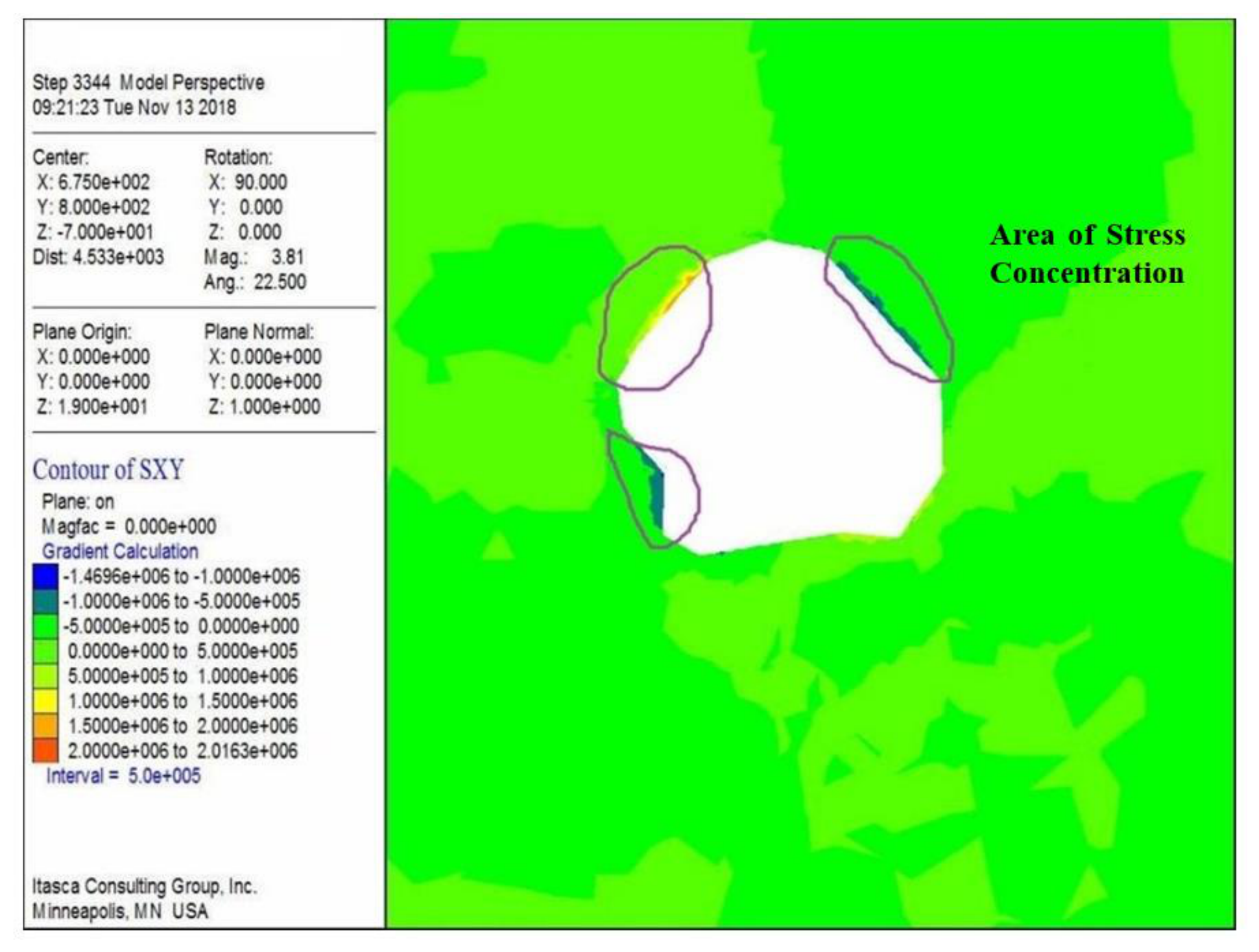
Figure 2.
Underground induced caving and roof cutting technique scheme with engineering layout diagram.
Figure 2.
Underground induced caving and roof cutting technique scheme with engineering layout diagram.

Figure 3.
Three-dimensional map of hole layout for Underground induced caving and roof cutting technique scheme.
Figure 3.
Three-dimensional map of hole layout for Underground induced caving and roof cutting technique scheme.
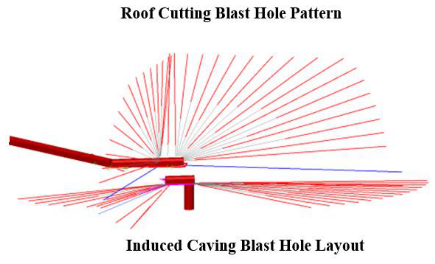
Figure 4.
Detonation connection diagram of blast hole.
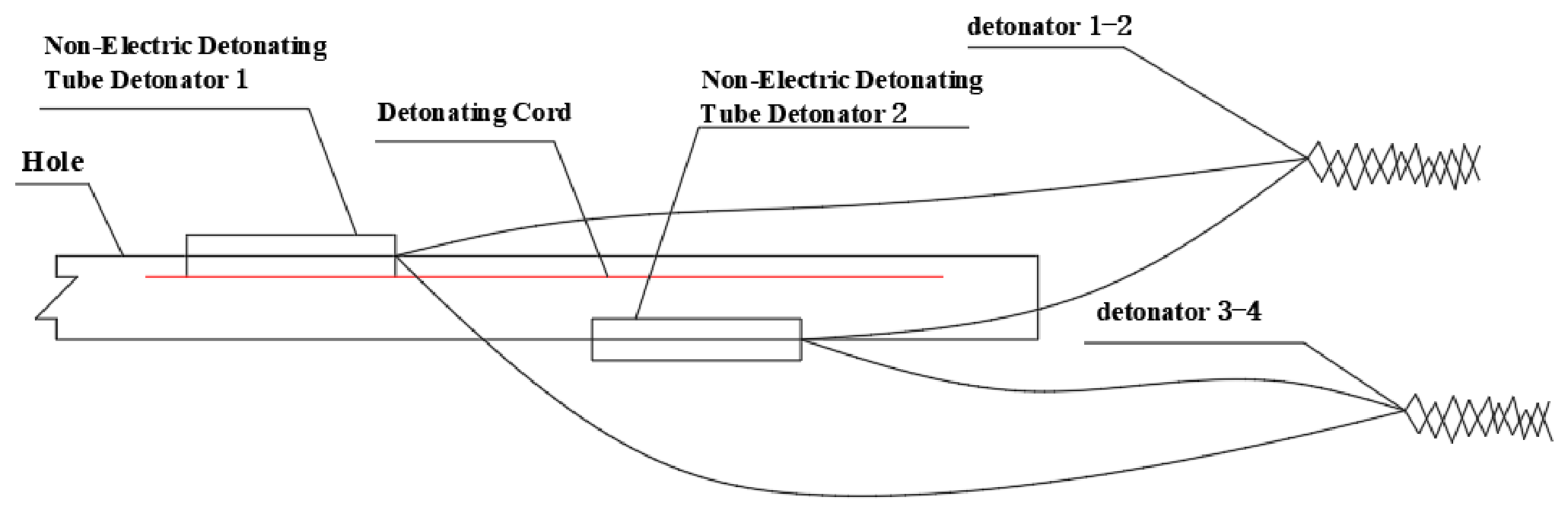
Figure 5.
Field Charging Operation Photo.
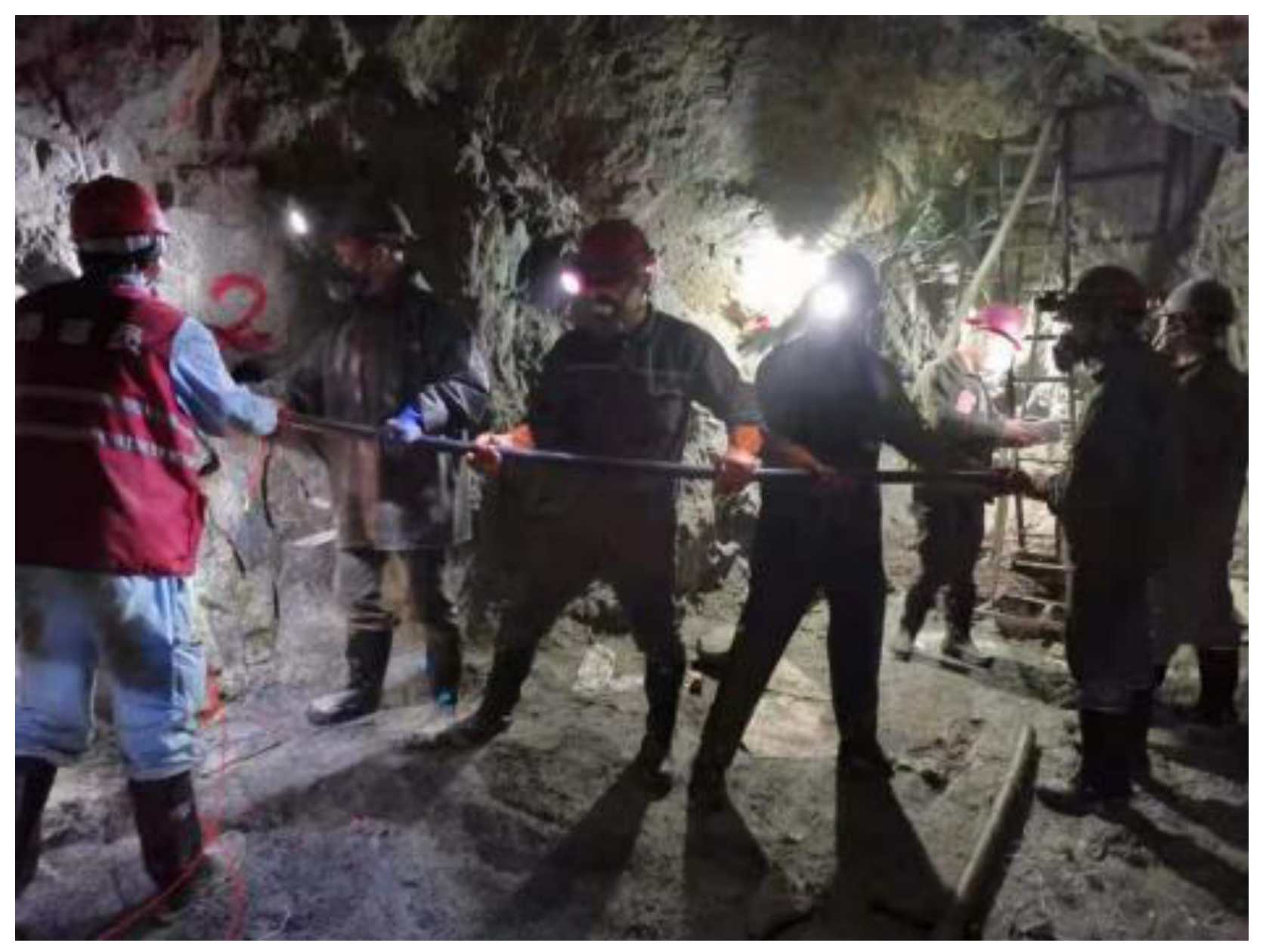
Figure 6.
Surface collapse pit.
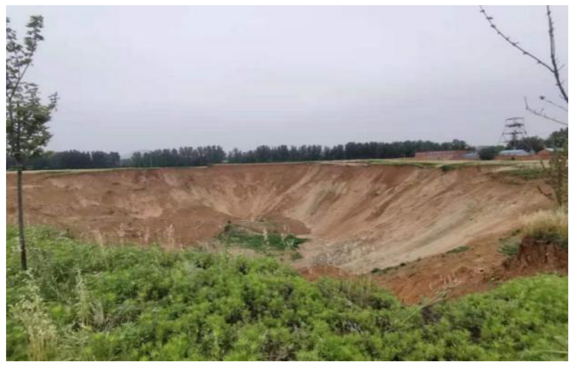

Table 1.
Statistics of mined-out area.
| Horizontal high | Type of mined-out area | Maximum span(m) | Exposed area(m2) | Volume(m3) | Connectivity |
Pillar area (m2) |
| -5m | mined-out area of room-pillar method | 175 | 7426 | 55695 | unconnected | 538 |
| mined-out area of sublevel caving method without sill pillar | 165 | 14905 | 253385 | all connected | no pillar | |
| -20m | mined-out area of room-pillar method | 160 | 19218 | 142631 | unconnected | 1958 |
| mined-out area of sublevel caving method without sill pillar | 140 | 13475 | 202125 | all connected | no pillar | |
| -40m | mined-out area of room-pillar method | 65 | 18946 | 139625 | unconnected | 1611 |
| mined-out area of sublevel caving method without sill pillar | 140 | 8555 | 171100 | all connected | no pillar | |
| extreme value | / | 175 | 19218 | 253385 | / | / |
Table 2.
Comparison table of mined-out area treatment schemes.
| Scheme | Advantages | Disadvantages |
| Induced roof caving to form a caved rock coverage layer for mined-out area remediation | The treatment process is mature, and the technical difficulty is small; the use of existing projects is easy to implement; the surface soil enters the underground less | Large amount of work; long construction time |
| Underground roof cutting induces overall caving to treat the mined-out area | The engineering quantity is small; less direct investment | The underground construction is difficult and the technical requirements are high; After the roof collapses, the soil enters the underground, and the dilution increases, which affects the mining operation |
| Surface-based ring-cutting induced caving for mined-out area remediation | Short construction time; the surface operation conditions are good | The blasting charge process is complex; after the roof collapses, the soil enters the underground, and the dilution increases, which affects the mining operation |
Table 3.
Engineering quantity statistics table.
| Item | Number of blast holes | Number of charged holes | Total blast hole length(m) | Charge length(m) | Charge weight(Kg) | |
| southeast engineering | induced caving chamber | 56 | 34 | 2443.1 | 1001.6 | 9014.4 |
| roof cutting chamber | 41 | 41 | 2032.5 | 1222 | 7332 | |
| Total | 97 | 75 | 4475.6 | 2223.6 | 16346.4 | |
| northeast engineering | induced caving chamber | 34 | 29 | 1399.3 | 536.9 | 4832.1 |
| roof cutting chamber | 85 | 85 | 3235.3 | 1997.2 | 11983.2 | |
| Total | 119 | 114 | 4634.6 | 2534.1 | 16815.3 | |
| western engineering | induced caving chamber | 82 | 53 | 3917.6 | 1656.5 | 14908.4 |
| roof cutting chamber | 42 | 42 | 2043.4 | 1260.2 | 7561.2 | |
| Total | 124 | 95 | 5961 | 2916.7 | 22469.6 | |
| Grand Total | data | 340 | 284 | 15071.2 | 7674.4 | |
Table 4.
The main blasting equipment consumption table of the project.
| Item | Unit | Quantity | Remarks |
| emulsion explosive | t | 55.6 | Drug-containing rolls and returning powder |
| detonator | unit | 1361 | MS1~MS15 |
| non-electric detonator | m | 28500 | / |
| electronic detonator | unit | 4 | / |
| detonating cord | m | 9209 | / |
Disclaimer/Publisher’s Note: The statements, opinions and data contained in all publications are solely those of the individual author(s) and contributor(s) and not of MDPI and/or the editor(s). MDPI and/or the editor(s) disclaim responsibility for any injury to people or property resulting from any ideas, methods, instructions or products referred to in the content. |
© 2026 by the authors. Licensee MDPI, Basel, Switzerland. This article is an open access article distributed under the terms and conditions of the Creative Commons Attribution (CC BY) license (http://creativecommons.org/licenses/by/4.0/).
Copyright: This open access article is published under a Creative Commons CC BY 4.0 license, which permit the free download, distribution, and reuse, provided that the author and preprint are cited in any reuse.