

Submitted:
09 September 2026
Posted:
09 September 2026
You are already at the latest version
Abstract
Unintended electromagnetic radiation and coupling arise when conductors, cables, traces, enclosures, and other structures support current and voltage distributions that allow them to behave partially as antennas. Conventional electromagnetic compatibility and signal-integrity theory describes these effects through impedance, common-mode and differential-mode currents, parasitic capacitance and inductance, transmission-line behavior, resonance, shielding, grounding, near-field coupling, and radiated emissions. These methods provide the quantitative foundation for engineering analysis. This article develops a complementary structural interpretation within the Beyond Field-Line Descriptions framework. The proposed Photony model treats unintended radiating structures as distributed electron-transduction systems in which internal electrons predominantly support magnetic structuring associated with current, while surface-associated electrons predominantly support electric structuring associated with voltage and surface charge. Geometry, discontinuities, conductor length, return-path configuration, and frequency determine where these structures become concentrated, reflected, redistributed, or released. Particular attention is given to unintended antenna formation, common-mode excitation, conductor and cable asymmetry, standing-wave development, surface localization, and the transition from source-coupled electromagnetic structuring to unwanted outward radiation or coupling. Signal-integrity effects are interpreted as changes in the spatial and temporal organization of the same electromagnetic energy that conventional theory describes through fields, voltages, currents, and Poynting transport. The framework is intended as a structural interpretation of established EMC and signal-integrity behavior rather than a replacement for conventional equations.
Keywords:
electromagnetic compatibility
; signal integrity
; unintended antennas
; common-mode current
; electromagnetic coupling
; standing waves
; electron transduction
; electric structuring
; magnetic structuring
; Photony
; mode conversion
; egress
; ingress
; EMI
; EMC
; radiation
; susceptibility
; coupling
; transduction
; elemental charge photons
; photons
; electric chains
; magnetic chains
1. Introduction
Unintended electromagnetic coupling and radiation are persistent challenges in electronic systems because an electrical signal is never only a numerical voltage or current at a circuit node. Once launched into an interconnect, the signal becomes a spatially distributed electromagnetic process involving a signal path, a return path, surrounding dielectric and conductive structures, and electromagnetic energy transport. Printed-circuit traces, cables, connector leads, reference planes, enclosure seams, shields, and chassis structures can therefore participate in the propagation, redistribution, coupling, or release of electromagnetic energy. The same physical conditions that degrade the intended signal can also produce electromagnetic compatibility problems.
Signal integrity (SI) concerns the preservation of the intended signal as it propagates through an interconnect or system. Its degradation may appear as noise, reflection, ringing, overshoot, undershoot, distortion, loss, delay, skew, crosstalk, or repeated threshold crossings. Electromagnetic compatibility (EMC) addresses the ability of a system to operate acceptably within its electromagnetic environment. From the system boundary, EMC includes both unwanted electromagnetic energy leaving the system, which is referred to here as egress, and unwanted electromagnetic energy entering the system and producing susceptibility, which is referred to here as ingress. Signal integrity and EMC are therefore closely related descriptions of what happens when electromagnetic energy does, or does not, remain organized within its intended geometry.
A useful engineering way to understand this behavior is to follow the signal itself. Dr. Eric Bogatin has described this perspective through the phrase “Be the Signal,” emphasizing the importance of considering what a propagating signal encounters as it moves through an interconnect. In that sense, the relevant questions are not limited to the voltage measured at the source or load. One must ask how the signal is launched, where its return is located, what impedance and geometry it encounters, whether it reflects, where its electromagnetic structure extends, what nearby structures it can couple to, and where its energy ultimately goes.
The present article extends that perspective one level further. Once the engineer has learned to “be the signal,” the Beyond Field-Line Descriptions framework asks what physical electromagnetic organization constitutes that signal and how that organization changes during propagation, reflection, coupling, and radiation. Conventional electromagnetic and transmission-line theory remain the quantitative foundation. The additional question is structural: what is physically being reorganized when a signal encounters a discontinuity, transfers energy to another conductor, develops common-mode behavior, or becomes an unintended radiator?
The preceding article in the Beyond Field-Line Descriptions series provides an important bridge between ordinary guided signal transport and the unintended electromagnetic behavior considered here by examining an intended dipole antenna as a distributed electron-transduction structure. In that treatment, high-current regions were associated predominantly with magnetic structuring through internal electrons, while high-voltage regions were associated predominantly with electric structuring through surface-associated electrons. The standing-wave current and voltage distributions were interpreted as spatially varying expressions of one electromagnetic organization, with dynamic elemental charge photons supporting current and magnetic transduction and static elemental charge photons accumulated at conductor surfaces supporting voltage and electric transduction. Reduction, reversal, and pinch-off were then proposed as the mechanisms through which source-coupled structuring becomes outward electromagnetic radiation.
The same physical processes can occur in structures that were never intended to function as antennas. A conductor need not be deliberately shaped as a resonant radiator before it can support distributed electromagnetic behavior. If its length, geometry, return-path configuration, frequency, impedance discontinuities, or surrounding structures allow substantial spatial variation of current and voltage, the conductor can develop localized regions of magnetic and electric structuring similar in principle to those of an intended antenna. The distinction is therefore not that an intended antenna possesses electromagnetic structuring while an unintended conductor does not. Rather, the distinction lies in whether the geometry and excitation were deliberately chosen to control that structuring and its release.
Within the proposed Photony interpretation, a propagating electrical signal is treated as an organized electromagnetic energy-transport process supported by dynamic and static elemental charge-photon populations and their interaction with electrons. Dynamic elemental charge photons associated with current interact predominantly with internal electrons and support magnetic-chain transduction, whereas static elemental charge photons accumulated at conductor surfaces interact predominantly with surface-associated electrons and support electric-chain transduction. Voltage, current, conductor geometry, return-path geometry, frequency, and boundary conditions therefore determine not merely the numerical values measured along an interconnect, but also where the proposed electric and magnetic structures become concentrated, extended, reduced, reflected, redistributed, coupled, or released.
The transfer of an unwanted disturbance from a source to a victim can be organized around four principal electromagnetic coupling mechanisms: conductive, capacitive, inductive, and radiative coupling. Conductive coupling transfers a disturbance through a shared or connected conductive structure. Capacitive coupling is associated primarily with voltage, surface charge, mutual capacitance, and . Inductive coupling is associated primarily with current, loop geometry, mutual inductance, and . Radiative coupling occurs when an electromagnetically significant structure launches propagating energy into the surrounding region and another structure intercepts part of that energy. More than one mechanism can operate simultaneously, and a disturbance may pass through different mechanisms as it travels from its original source to its eventual victim. These four mechanisms provide a recurring organizational framework for the remainder of this article.
This perspective is particularly important for common-mode behavior. Differential-mode excitation is normally associated with closely related signal and return paths whose opposing current and charge distributions constrain much of the electromagnetic organization to a relatively compact region. Common-mode excitation can instead involve a much larger unintended geometry that includes cables, shields, chassis structures, reference planes, connectors, attached conductors, and portions of the surrounding environment. Conventional EMC theory recognizes that relatively small common-mode currents can consequently produce disproportionately large radiated emissions when they excite electrically significant conductors. Within the Beyond Field-Line interpretation, common-mode conversion represents a redistribution of the same electromagnetic energy into a larger electron-transduction geometry rather than the creation of a separate form of energy.
Signal-integrity degradation and EMC behavior are therefore not independent phenomena. Reflections, overshoot, undershoot, ringing, crosstalk, return-path discontinuities, resonances, and mode conversion are conventionally described through transmission-line propagation, distributed impedance, capacitance, inductance, and electromagnetic coupling. The same event that distorts an intended waveform can also enlarge the electromagnetic geometry, increase coupling to neighboring structures, generate common-mode current, or create an effective unintended antenna. Within the proposed Photony interpretation, these phenomena correspond to changes in the spatial and temporal organization of the dynamic and static elemental charge-photon populations and in the electron-mediated electric and magnetic structures associated with them. An impedance discontinuity therefore does more than alter a numerical impedance: it changes the local conditions under which electromagnetic energy can continue, reflect, accumulate at surfaces, couple into another structure, or become released.
A useful system-level representation is therefore
The source produces the electromagnetic disturbance, the coupling path transfers some portion of that disturbance through one or more of the four coupling mechanisms, and the victim responds to the received energy. The same physical structure can change roles as the disturbance propagates. A PCB trace may begin as the intended signal path, a discontinuity may convert part of its electromagnetic organization into common mode, an attached cable may become an unintended radiator, and a neighboring conductor may become the victim. That victim can, in turn, become a secondary source.
The objective of this article is therefore to develop a unified structural interpretation of signal integrity, electromagnetic compatibility, and unintended antenna behavior while retaining conventional electromagnetic theory as the quantitative constraint. The analysis first establishes the conventional relationships governing distributed interconnects, transmission-line propagation, signal and return paths, reflections, standing waves, differential and common modes, frequency-dependent current localization, and electromagnetic energy transport. It then develops the proposed Photony description of the signal as an electron-mediated organization of dynamic and static elemental charge-photon populations. The four coupling mechanisms, conductive, capacitive, inductive, and radiative, are subsequently examined as distinct but interrelated pathways through which electromagnetic energy can move from source to victim. Discontinuities, common-mode (mode)conversion, ingress, egress, unintended antenna formation, and practical SI/EMC design are then interpreted within the same framework. Particular attention is given to identifying where conventional measurable behavior ends and the proposed Photony structural interpretation begins.
2. Conventional Electromagnetic Description of Unintended Antennas and Coupling
Unintended electromagnetic behavior begins with the same physical structures that carry intended power and signals. Traces, cables, connectors, reference planes, shields, chassis structures, and enclosure features can support distributed voltage and current, provide return paths, store reactive electromagnetic energy, couple energy to neighboring structures, and, under appropriate conditions, radiate. Conventional electromagnetic compatibility and signal-integrity theory describes these behaviors through transmission-line propagation, impedance, differential-mode and common-mode current, parasitic capacitance and inductance, reflections, resonance, return-path geometry, shielding, frequency-dependent current distribution, near-field coupling, and radiation Bogatin (2018); Ott (2009); Paul (2006). These established relationships provide the quantitative constraints for the structural interpretation developed later.
The purpose of this section is to follow the electromagnetic signal from controlled propagation toward progressively less confined behavior. The discussion begins with the transition from lumped to distributed operation, then considers differential and common modes, signal and return geometry, reflections and resonance, parasitic interactions, coupling between structures, frequency content, current localization, and finally outward radiation. Particular attention is given to identifying how the same electromagnetic disturbance can remain within its intended path, couple to another structure, or become part of an unintended antenna.
2.1. From Lumped Circuit Behavior to Distributed Electromagnetic Propagation
At sufficiently low frequency, an interconnect can often be approximated as a lumped structure whose voltage and current are effectively uniform over its physical dimensions. As the significant frequency content increases, however, propagation time becomes comparable with the timescale of signal variation. Voltage and current can no longer be assumed to have the same magnitude and phase everywhere along the structure, and the interconnect must be treated as a distributed electromagnetic system.
A useful criterion is based on the ratio of physical length L to wavelength ,
The wavelength is
where is the propagation velocity in the relevant medium and f is frequency.
As increases, phase differences along the conductor become increasingly important. The conductor can then support traveling waves, reflections, standing-wave patterns, and spatially nonuniform current and voltage distributions Bogatin (2018); Pozar (2012).
For signal-integrity analysis, the relevant wavelength is associated with the significant spectral content of the waveform, not necessarily with the clock or repetition frequency alone. A fast digital transition can therefore make an interconnect electromagnetically distributed even when the nominal operating frequency appears comparatively low. This point becomes especially important later when edge rate and unintended antenna excitation are considered.
This transition is fundamental to unintended antenna behavior. A cable, trace, shield, enclosure seam, reference structure, or other conductor need not be designed as an antenna before it can support an electrically significant current or voltage distribution. Once its physical dimensions become sufficiently large relative to the wavelengths of the significant signal components, the structure can interact strongly with the surrounding electromagnetic environment.
2.2. Differential-Mode and Common-Mode Excitation
One of the most important distinctions in EMC analysis is between differential-mode and common-mode current.
In an ideal differential structure, equal and opposite currents flow in the signal and return conductors,
The associated electric and magnetic fields are concentrated primarily between or near the conductors. Because the opposing currents and charges are closely spaced, far-field radiation can be comparatively small when the geometry is well balanced [3,4].
Common-mode excitation occurs when currents on nominally paired conductors are no longer equal and opposite. A common-mode current may be represented as
while the differential-mode current is commonly represented as
Equations 5 and 6 distinguish two fundamentally different electromagnetic geometries. In a well-balanced differential structure, opposing currents and associated charge distributions remain closely related spatially, so much of the external electromagnetic field is confined or canceled at distances large compared with the conductor spacing.
Common-mode excitation occurs when part of that balance is lost. The resulting current need not return through the immediately adjacent intended conductor and may instead involve reference planes, shields, chassis structures, cables, attached conductors, parasitic capacitances, or other parts of the larger system. The effective electromagnetic geometry can therefore become much larger than the original signal-return pair.
This distinction is central to EMC because radiation efficiency depends not only on current magnitude but also on the geometry over which that current is distributed. Relatively small common-mode currents can consequently dominate radiated emissions when they excite electrically significant cables, shields, chassis structures, or other extended conductors Ott (2009); Paul (2006).
2.3. Return Paths and Electromagnetic Geometry
The phrase “current path” is incomplete unless the return path is also specified. At high frequency, the return current is determined by the impedance of the complete electromagnetic structure rather than simply by the geometrically shortest conductive route. Inductance, capacitance, conductor geometry, nearby reference surfaces, and frequency all influence the return distribution Bogatin (2018); Paul (2006).
For a well-controlled transmission structure, the signal and return remain closely associated. The resulting loop area is comparatively small and much of the electromagnetic energy remains concentrated in the region between and immediately surrounding the two paths. In this sense, preserving return-path continuity is not merely a grounding practice; it is a means of preserving the intended electromagnetic geometry of the signal.
If the return path is interrupted, displaced, or forced around a discontinuity, the electromagnetic geometry expands. The effective loop area generally increases, field confinement is reduced, and capacitive, inductive, common-mode, and radiative interactions can become more significant.
This behavior may be summarized qualitatively as
This relationship is especially important in printed-circuit boards, cable assemblies, connectors, shields, and enclosure transitions. A signal trace crossing a reference-plane gap, a poorly bonded shield, an inadequately referenced connector transition, or a displaced return conductor can force the signal-return system to reorganize over a larger physical region. The resulting disturbance may remain a signal-integrity problem, may couple to another structure, or may contribute to common-mode excitation and unintended radiation.
2.4. Transmission-Line Behavior and Reflections
When an interconnect becomes electrically distributed, its voltage and current may be represented as combinations of forward- and backward-traveling waves. For an ideal transmission line,
and
where is the characteristic impedance and is the phase constant Pozar (2012).
This distributed description is the mathematical basis for the “Be the Signal” perspective introduced in Section 1. A propagating disturbance encounters the impedance and geometry presented locally by the interconnect. When those conditions remain uniform, the signal can continue with little reflection. When the local electromagnetic environment changes, part of the disturbance may be transmitted, reflected, redistributed, or coupled elsewhere.
At a load impedance , the voltage reflection coefficient is
Equation 9 quantifies the division that occurs when a traveling wave encounters an impedance different from . The reflected component carries electromagnetic energy back toward the source while the transmitted component continues into the new structure.
In signal-integrity analysis, these reflected components can produce overshoot, undershoot, ringing, multiple transitions, and timing errors. The same redistribution can also increase local current or voltage maxima, enlarge the surrounding electromagnetic field, excite common-mode current, or enhance coupling and radiation.
An impedance discontinuity is therefore important to both SI and EMC. It changes not only the waveform observed at a measurement point, but also the spatial distribution and subsequent pathways of electromagnetic energy within the system.
2.5. Standing Waves and Resonance
Forward and reflected waves can combine to produce standing-wave patterns. Under resonant conditions, relatively large local current or voltage amplitudes can develop even when the source excitation is modest.
The resonance condition depends on geometry, boundary conditions, loading, and propagation velocity. A simplified open or shorted structure may exhibit strong resonances when its electrical length approaches fractions of a wavelength, such as
depending on the specific boundary conditions.
These relationships explain why cables, traces, enclosure seams, and other conductors can become efficient unintended antennas at particular frequencies. The physical structure may not have been designed for resonance, yet its dimensions and terminations can satisfy electromagnetic boundary conditions that produce strong current or voltage distributions.
The result can be enhanced radiation, susceptibility, or coupling to nearby structures. Resonance therefore provides a mechanism by which a modest source disturbance can become spatially concentrated at particular current or voltage maxima. These maxima will later be important to the Photony interpretation because current-dominant and voltage-dominant regions are associated with different electron-transduction processes.
2.6. Parasitic Capacitance and Inductance
No practical conductor exists in electromagnetic isolation. Nearby conductors, dielectric materials, chassis surfaces, reference planes, shields, and enclosures produce distributed capacitance and inductance.
A small parasitic capacitance has impedance
while a parasitic inductance has impedance
As frequency increases, capacitive impedance decreases while inductive impedance increases. Structures that appear electrically isolated at low frequency can therefore become strongly coupled at high frequency, while seemingly negligible conductor lengths can develop substantial inductive voltage drops.
The resonant frequency of an idealized parasitic combination is
Equation 13 illustrates why unintended resonances can arise from ordinary physical construction. Connector pins, package leads, vias, cable shields, enclosure seams, reference structures, and board geometries all contain distributed inductive and capacitive behavior. These parasitic elements are therefore not merely corrections to an ideal circuit schematic; they create physical pathways through which electromagnetic energy can be stored, redirected, and coupled between structures.
2.7. The Four Principal Electromagnetic Coupling Mechanisms
A disturbance reaches a victim through a physical coupling path. For the purposes of this article, four principal coupling mechanisms are distinguished: conductive, capacitive, inductive, and radiative coupling. More than one mechanism can act simultaneously, and a disturbance may change coupling mechanism as it propagates through a system Bogatin (2018); Ott (2009); Paul (2006).
2.7.1. Conductive Coupling
Conductive coupling occurs when source and victim share a conductive path or impedance. Examples include common power or reference conductors, shared return structures, cable shields, interconnect resistance or inductance, and other direct conductive connections. A disturbance current flowing through a shared impedance can produce a voltage that is experienced by another circuit,
Conductive coupling therefore depends not only on the magnitude of the disturbance current but also on the impedance and geometry of the shared path. At high frequency, even physically short conductors can develop sufficient inductive impedance to produce significant coupled voltage.
2.7.2. Capacitive Coupling
Capacitive coupling is associated primarily with time-varying voltage and electric-field interaction between conductors. A changing source voltage can drive displacement current through a mutual capacitance ,
where is the mutual capacitance between the source and victim structures.
Capacitive coupling is promoted by large , relatively large opposing conductive areas, small separation, and dielectric geometries that increase mutual capacitance. It can occur between traces, cables, connector conductors, heatsinks, chassis structures, enclosure surfaces, and other electrically separated conductors.
2.7.3. Inductive Coupling
Inductive coupling is associated primarily with time-varying current and magnetic interaction between current loops. A changing source current can induce a voltage in a victim circuit according to
where M is the mutual inductance.
Inductive coupling is promoted by large , large effective loop area, strong geometric linkage, and close proximity between source and victim current paths.
2.7.4. Radiative Coupling
Radiative coupling becomes important when the source structure supports current and charge distributions capable of launching propagating electromagnetic energy into the surrounding region. A receiving structure can then intercept part of that energy without requiring a shared conductive path or a predominantly reactive near-field interaction.
The distinction between radiative and near-field coupling is not determined by one universal distance alone. It depends on wavelength, source dimensions, geometry, and the electromagnetic region being considered. Nevertheless, at sufficiently large distance from a radiating source, the electric and magnetic components become predominantly transverse and the outward power flow is described by the Poynting vector.
The four mechanisms can therefore be summarized conventionally as
and represented at the system level as
This four-mechanism framework will be retained throughout the remainder of the article and reinterpreted structurally within the proposed Photony model beginning in Section 3.
2.7.5. Crosstalk as Distributed Capacitive and Inductive Coupling
For nearby transmission lines, capacitive and inductive coupling act continuously along the coupled length. The resulting disturbance is commonly classified according to where it is observed. Near-end crosstalk (NEXT) is measured at the end of the victim line nearest the source end of the aggressor line, whereas far-end crosstalk (FEXT) is measured at the opposite end of the victim line Bogatin (2018); Paul (2006).
The distinction may be summarized as
and
The relative magnitudes and polarities of NEXT and FEXT depend on geometry, propagation velocity, coupled length, termination conditions, mutual capacitance, and mutual inductance. In high-speed digital systems, even relatively weak distributed coupling can become significant when edge rates are fast and parallel coupled lengths are substantial.
2.8. Frequency Content and Edge Rate
Digital signals are not single-frequency waveforms. A transition contains a spectrum of frequency components, and the significant high-frequency content can extend far above the nominal clock or repetition frequency. Consequently, an interconnect that appears electrically short when judged only by its clock frequency can behave as a distributed electromagnetic structure for the faster components of the transition Bogatin (2018).
This distinction is important for both SI and EMC because faster edges increase , , and high-frequency spectral content simultaneously. Capacitive and inductive coupling can therefore increase, smaller discontinuities become electromagnetically significant, and shorter physical structures can behave as unintended antennas.
The qualitative progression is
The physical dimensions of the system should therefore be compared with the wavelengths associated with the significant spectral components of the signal rather than with the nominal clock frequency alone.
2.9. Frequency-Dependent Current Localization
Frequency also changes the distribution of current within the conductor itself. For a good conductor, the conventional skin depth is
where is angular frequency, is permeability, and is conductivity.
Equation 17 shows that skin depth decreases approximately as the inverse square root of frequency. Increasing frequency therefore concentrates conventional current density progressively toward conductor surfaces. Chapter 8 of Photony Foundations illustrates this progression for round and rectangular conductors and provides the basis for the later structural interpretation Martin (2022).
Figure 1 emphasizes that the conductor cannot be treated as having a frequency-independent internal current distribution. At sufficiently low frequency, current can occupy much of the available cross-section. As frequency increases, the highest current density moves progressively toward the surface. For rectangular structures, the geometry produces nonuniform localization across different dimensions, so the effective current distribution can differ substantially from that of a round wire.
This behavior is particularly important for EMC and signal integrity because many practical high-frequency conductors are not round. Printed-circuit traces, planes, shields, enclosure walls, connector structures, and bus conductors have strongly geometry-dependent current distributions. Changes in the location and concentration of current alter resistance, inductance, loss, field confinement, return-path behavior, and the degree to which neighboring structures can be electromagnetically coupled.
The frequency-dependent localization illustrated in Figure 1 becomes especially important in Section 3. Conventional skin effect describes where measurable current density becomes concentrated; the proposed Photony interpretation asks how that localization relates to dynamic elemental charge-photon transport, internal-electron transduction, surface encounters, and the distinction between current-associated magnetic structuring and surface-associated electric structuring.
2.10. From Coupled Electromagnetic Structure to Radiation
When time-varying currents and charges extend over an electromagnetically significant structure, part of the electromagnetic energy can propagate outward rather than remaining predominantly associated with the source structure or its reactive near field. An unintended antenna is therefore not distinguished by a different radiation law from an intended antenna. The distinction lies in how the radiating current and charge distribution came to exist.
The conventional energy-flux description is the Poynting vector,
with total outward radiated power given by
Equations 18 and 19 apply whether the radiating structure was intentionally designed as an antenna or acquired that behavior unintentionally through geometry, common-mode excitation, resonance, or discontinuity.
Maxwell’s equations do not contain a distinction between an intended and unintended antenna. That distinction is engineering in nature involving function, geometry, excitation, confinement, and design intent. The preceding intended-antenna article examined deliberately organized electromagnetic release; the present article considers how similar outward energy transport can arise accidentally from structures whose primary purpose is signal or power conduction.
2.11. Conventional Constraints on the Beyond Field-Line Interpretation
The structural interpretation developed in the following sections must remain consistent with the established electromagnetic behavior summarized above. In particular, it must preserve the following conventional results:
- Electrically significant interconnects support distributed voltage and current rather than purely lumped behavior.
- A signal and its return form a coupled electromagnetic geometry, and disruption of that geometry can increase field extent, coupling, and radiation.
- Impedance discontinuities produce transmitted and reflected electromagnetic components.
- Differential-mode and common-mode excitation can produce substantially different external electromagnetic behavior.
- Resonance can reinforce local current and voltage maxima and can convert otherwise ordinary conductors into efficient unintended electromagnetic structures.
- Conductive, capacitive, inductive, and radiative coupling provide the principal pathways by which a disturbance can transfer from source to victim.
- Fast transitions increase significant high-frequency content as well as and , thus increasing sensitivity to distributed geometry and coupling.
- Increasing frequency changes the current distribution within conductors through skin effect and related geometry-dependent localization.
- All outward electromagnetic transport must remain consistent with energy conservation and the Poynting-vector description of electromagnetic power flow.
The Beyond Field-Line interpretation does not replace these relationships. Instead, it asks what physical organization may underlie them. Section 3 therefore shifts the level of description from measured voltage, current, impedance, and field quantities to the proposed dynamic and static elemental charge-photon populations, electron transduction, electric and magnetic chain organization, surface accumulation, reduction, redistribution, and electromagnetic release.
3. Electron Transduction and Electromagnetic Organization in Unintended Structures
Section 2 established the conventional constraints that govern signal propagation, reflection, coupling, common-mode behavior, and unintended radiation. Electrically significant conductors support distributed current and voltage, signal and return paths form a coupled electromagnetic geometry, discontinuities redistribute electromagnetic energy, and conductive, capacitive, inductive, and radiative coupling provide principal pathways through which disturbances can move from source to victim. The present section shifts the level of description from those measurable circuit and field quantities to the proposed Photony structural interpretation.
Within the Photony framework, a propagating electrical signal is treated as an organized electromagnetic energy-transport process involving elemental charge photons and electron-mediated transduction. Dynamic elemental charge photons are associated primarily with current flow, while static elemental charge photons can accumulate at conductor surfaces and are associated primarily with voltage and surface charge. Electrons serve as transducers and regulators between these populations and the electric and magnetic chain structures proposed to constitute electromagnetic fields Martin (2022).
An unintended antenna is therefore not assigned a fundamentally different microscopic mechanism from an intended antenna. The same electron-mediated electric and magnetic organization can occur whenever conductor geometry, excitation, frequency, return-path configuration, and boundary conditions establish distributed current and voltage. The distinction is one of function and control. In an intended antenna, geometry and excitation are selected deliberately to organize and release electromagnetic energy. In an unintended structure, comparable organization develops accidentally.
3.1. Dynamic and Static Elemental Charge-Photon Populations
A central distinction in the proposed framework is between dynamic elemental charge photons participating in current transport and static elemental charge photons associated with surface accumulation.
The current-associated population may be represented qualitatively as
The voltage-associated surface population may be represented as
These relationships are proposed structural interpretations rather than replacements for conventional definitions of current, charge, or voltage. Their purpose is to identify the two elemental charge-photon populations that participate differently in the electron-transduction processes developed below.
3.2. Internal and Surface Electron Transduction
Photony Foundations distinguishes two principal electromagnetic chain populations associated with conductors. Internal electrons interacting predominantly with the dynamic elemental charge-photon population are proposed to transduce magnetic chain loops, while surface-associated electrons interacting predominantly with accumulated static elemental charge photons are proposed to transduce electric chains Martin (2022).
The magnetic process can be summarized as
while the electric process can be summarized as
These two processes are complementary expressions of one electromagnetic system. A practical conductor can support both simultaneously, but their relative prominence varies with position and time according to local current, voltage, geometry, frequency, and boundary conditions.
Figure 2 provides the conductor-scale structural picture used throughout the remainder of this article. Regions supporting relatively large current favor stronger magnetic transduction through internal electrons, while regions supporting relatively large voltage and surface accumulation favor stronger electric transduction through surface-associated electrons.
These regions do not have to be intentionally designed. Impedance changes, connector transitions, reference-plane interruptions, cable terminations, shield openings, asymmetries, and resonant conductor lengths can all modify the local current and voltage distribution. The proposed electron-transduction organization follows those altered conditions.
3.3. The Signal as a Distributed Transduction Process
The “Be the Signal” perspective introduced in Section 1 asks the engineer to follow a propagating disturbance through the structure and consider what impedance, return path, discontinuities, coupling opportunities, and terminations it encounters. The Photony interpretation extends that thought process by asking what underlying electromagnetic organization accompanies the signal.
Within this framework, a signal is not represented structurally by one isolated voltage quantity or one stream of moving charge. It is an evolving combination of dynamic elemental charge-photon transport, surface accumulation, internal-electron magnetic transduction, surface-electron electric transduction, and the surrounding electric and magnetic chain organization.
This motivates a complementary Photony thought experiment: to “be the photon” is to follow the proposed elemental charge-photon population through the same electromagnetic structure. The questions then become: Where does the dynamic population propagate? Where does it encounter a discontinuity or conductor surface? Where does static accumulation increase? Which electron populations transduce magnetic or electric chains? Where are those chains reduced or reorganized? Where does electromagnetic organization remain confined, where does it couple to another structure, and where can it become outward-propagating radiation?
In this sense, “Be the Signal” and “Be the Photon” operate at different descriptive levels. The first follows the measurable signal through a distributed interconnect. The second follows the proposed microscopic organization underlying the same propagation.
3.4. Unintended Structures as Distributed Transduction Systems
An intended dipole deliberately establishes spatially varying current and voltage conditions. An unintended antenna can establish comparable distributed conditions accidentally.
Within the proposed interpretation, any conductor system can become a distributed transduction structure when its dimensions, excitation, and boundary conditions become electromagnetically significant. The important point is not that every conductor is necessarily an efficient antenna, but that the same electron-transduction mechanisms remain available wherever distributed current and surface voltage develop.
A local electromagnetic state can therefore be considered qualitatively as containing both magnetic and electric contributions,
where represents the proposed magnetic-transduction contribution and represents the proposed electric-transduction contribution.
Equation 24 does not introduce a new measurable EMC parameter. It emphasizes that the proposed electromagnetic organization varies with both position and time.
In a well-controlled transmission structure, signal and return remain closely associated and much of the electric and magnetic organization remains confined to the intended geometry. When return continuity is lost, asymmetry develops, impedance changes, or common-mode current appears, that organization can extend over a larger region and interact more strongly with neighboring conductors or free space.
3.5. Current Redistribution and Surface Accumulation
Section 2 showed conventionally that current distribution depends on frequency, conductor geometry, impedance, and return-path configuration. Within the Photony interpretation, these changes correspond to redistribution of the underlying dynamic elemental charge-photon population.
Where dynamic transport remains strongly supported through the conductor, internal-electron magnetic transduction remains prominent. Where forward transport is altered and the dynamic population increasingly encounters conductor surfaces or boundaries, a portion of that population is proposed to contribute to static elemental charge-photon accumulation. Increased static surface population corresponds to an increased local voltage condition and stronger electric structuring Martin (2022).
The proposed sequence is
This process becomes particularly important at open ends, impedance transitions, reference-plane gaps, shield discontinuities, connector transitions, and resonant voltage maxima. What conventional signal-integrity theory identifies as redistribution of voltage and current at a discontinuity is therefore interpreted structurally as redistribution between dynamic transport, surface accumulation, and the associated electron-transduction states.
3.6. AC-Induced Electron Reorientation
Signal-integrity and EMC phenomena frequently involve alternating, transient, or digitally switched excitation. The local electron-transduction condition must therefore change repeatedly with the signal.
Within the Photony framework, an electron retains its intrinsic c-spin while an alternating electrical excitation can produce an externally driven end-over-end x-spin response Martin (2022). This reorientation changes the electron’s relationship to the local elemental charge-photon population and permits successive transduction and reduction states.
For a periodic excitation,
with angular frequency
The proposed electron response follows the local electrical condition rather than requiring every position along a distributed structure to change simultaneously. Traveling signals, reflections, standing waves, and coupled disturbances can therefore establish different transduction states at different locations at the same instant.
This local character is important for unintended structures. A cable, trace, shield, or reference plane can contain regions that are current dominant, voltage dominant, increasing, decreasing, or reversing at different positions as the propagating and reflected signal components evolve.
3.7. Transduction, Reduction, and Reversal
Within Photony, electron transduction is not proposed to continue monotonically as excitation decreases. A reduction in the available elemental charge-photon population at a transducing electron can cause the electron to reduce a previously transduced chain. Under alternating excitation, continuing reorientation then prepares the electron for transduction in the opposite direction.
The cycle may be represented qualitatively as
This behavior becomes particularly relevant to signals containing reflections, ringing, multiple transitions, and multiple frequency components. A location along an interconnect may undergo several intervals of growth, reduction, and renewed transduction even when the original source event consisted of a single edge.
A standing-wave structure provides another example. Current-dominant and voltage-dominant regions vary both spatially and temporally, repeatedly changing the local balance between magnetic and electric transduction. The proposed organization is therefore dynamic even when the conventional waveform appears periodic and stable.
3.8. Frequency-Dependent Localization and Electron Participation
The skin-effect behavior introduced in Section 2 provides an important connection between conventional current localization and the proposed electron-transduction model. As frequency increases, conventional current density becomes progressively concentrated nearer conductor surfaces. In noncircular structures such as traces, planes, shields, and enclosure walls, the localization is strongly dependent on geometry.
Within the Photony interpretation, this means that the dynamic elemental charge-photon population and the electron population participating most strongly in current-associated magnetic transduction become increasingly localized within particular conductor regions. At the same time, conductor surfaces remain the principal locations of static elemental charge-photon accumulation and electric transduction.
The result is not a claim that conventional skin effect is replaced by a new law. The conventional skin-depth relation remains the quantitative description. Photony instead proposes a structural interpretation of what the changing current distribution means for the spatial populations of charge photons and transducing electrons.
This distinction will become important when considering high-frequency coupling because capacitive interaction is strongly associated with surface voltage and electric organization, while inductive interaction is strongly associated with the geometry of current and magnetic organization.
3.9. Geometry as a Constraint on Electromagnetic Organization
Geometry is central to both conventional EMC engineering and the proposed structural interpretation. Conductor spacing, loop area, trace dimensions, reference-plane continuity, shield termination, connector arrangement, dielectric placement, and enclosure construction determine the electromagnetic environment through which a signal propagates Bogatin (2018); Ott (2009); Paul (2006).
Within Photony, geometry determines the pathways available to the dynamic elemental charge-photon population, where surface encounters occur, where static accumulation becomes concentrated, which electron populations participate most strongly in transduction, and how far the resulting electric and magnetic chain organization can extend.
The progression may be summarized as
For example, increasing the separation between a signal conductor and its return structure enlarges the conventional electromagnetic field region. Within the proposed interpretation, the same change allows the associated electric and magnetic chain organization to occupy a larger volume. Interrupting the nearby return path can force the dynamic population and associated transduction processes to redistribute through a different combination of conductive, capacitive, and surrounding electromagnetic pathways.
Geometry therefore does not merely determine where electromagnetic field lines are drawn. It determines where energy can be transported, stored, transduced, coupled, reflected, reduced, or released.
3.10. Differential and Common-Mode Structural Organization
The conventional distinction between differential-mode and common-mode excitation also has a direct structural counterpart.
In a well-balanced differential structure, the opposing signal and return currents remain spatially close. The associated magnetic organization and surface electric organization are correspondingly constrained to a relatively compact geometry. At distances large compared with the conductor separation, opposing contributions tend to reduce the external field.
When imbalance produces common-mode current, the effective electromagnetic structure expands. Cables, shields, reference planes, chassis surfaces, connector bodies, attached conductors, and parasitic return paths can become part of the same distributed system.
The qualitative distinction is
This provides a proposed structural explanation for an important conventional EMC observation: a common-mode current much smaller than the intended differential current can nevertheless produce substantial radiation if the common-mode current occupies a much larger and more electromagnetically efficient structure.
Within the present framework, differential-to-common-mode conversion therefore represents redistribution of existing electromagnetic energy into a different spatial organization. It does not require the creation of a new type of energy.
3.11. From “Be the Signal” to Source, Path, and Victim
The source-path-victim representation introduced in Section 1 can now be expressed at the Photony structural level.
The source establishes the initial dynamic and static elemental charge-photon populations and the associated electron-transduction state. The coupling path determines how some portion of that electromagnetic organization can leave its intended geometry. The victim provides another electron-containing structure capable of responding to the arriving disturbance.
Thus,
The physical structure can change roles as energy propagates. A signal trace can begin as the intended transport structure, a discontinuity can redistribute the organization, a cable or shield can become part of a common-mode structure, and that structure can then couple energy to a neighboring conductor or radiate into free space. A receiving structure can subsequently convert the arriving electromagnetic organization into an internal electrical disturbance and become a secondary source.
This progression illustrates why signal integrity and EMC cannot be separated completely at the physical level. Both concern the organization, transport, redistribution, and reception of electromagnetic energy.
3.12. Structural Basis of an Unintended Antenna
The preceding arguments lead to a structural definition of an unintended antenna within the proposed framework.
An unintended antenna is a conductor or collection of conductors in which geometry, frequency, return-path configuration, imbalance, discontinuity, or resonance permits ordinary electron-transduction processes to develop into a spatially extended electromagnetic organization capable of coupling significantly to another structure or propagating outward.
The progression can be represented as
This definition deliberately preserves the conventional distinction between intended and unintended radiation while proposing a common underlying structure. The same dynamic and static elemental charge-photon populations, electron transduction, magnetic chains, electric chains, reduction, and reorientation proposed for an intended antenna remain available in unintended structures. What changes is the geometry through which that organization develops and whether its outward coupling was deliberately designed.
3.13. Transition to the Four Coupling Mechanisms
Section 2 identified conductive, capacitive, inductive, and radiative coupling as the four main pathways through which an electromagnetic disturbance can transfer from the source to the victim. The present section has established the Photony elements needed to reinterpret those pathways structurally.
The correspondence that will be developed in the following section is qualitatively summarized as follows.
These correspondences are not proposed as replacements for shared-impedance analysis, mutual capacitance, mutual inductance, Maxwell’s equations, antenna theory, or the Poynting-vector description. They provide the structural Photony interpretation that will be developed for each coupling mechanism in Section 4.
4. Photony Interpretation of the Four Coupling Mechanisms
Section 2 and Section 3 established two complementary descriptions of electromagnetic coupling. Conventionally, a disturbance can reach a victim through conductive, capacitive, inductive, or radiative coupling. Structurally, the proposed Photony framework describes electrical signals in terms of dynamic elemental charge-photon transport, static surface accumulation, electron transduction, and the resulting electric and magnetic chain organization.
The purpose of the present section is to bring these descriptions together. The four coupling mechanisms are not treated as four unrelated phenomena. Rather, they represent four different ways in which electromagnetic energy associated with a source can reach another structure. More than one mechanism can operate simultaneously, and the dominant mechanism can change as the disturbance progresses from source to victim.
A useful overall representation is
The conventional equations remain the quantitative constraints. The Photony interpretation addresses the proposed physical organization that accompanies the transfer.
4.1. Conductive Coupling as Connected Electromagnetic Transport
Conductive coupling occurs when the source and victim are connected through a shared conductive structure or shared impedance. Conventional examples include power-distribution networks, reference conductors, ground structures, cable shields, connector conductors, and shared return paths. As developed in Section 2, a disturbance current flowing through a shared impedance can generate a coupled voltage according to
Within the Photony interpretation, conductive coupling represents the most direct of the four transfer mechanisms because the dynamic elemental charge-photon population can continue through a physically connected conductive system. The victim does not first require interception of an independently propagating radiative structure. Instead, the conducting network itself provides the pathway through which the electromagnetic organization is redistributed.
The proposed sequence is
A shared conductor can participate simultaneously in current transport, surface-charge redistribution, magnetic transduction, and electric transduction. Conductive coupling should therefore not be interpreted as transport that is somehow independent of electromagnetic organization. Rather, the conductive structure constrains where that organization can develop.
This interpretation is particularly relevant to common reference impedances and return-path interactions. A disturbance generated in one circuit can alter the current and surface-voltage conditions of a shared structure, thereby changing the transduction environment experienced by another circuit attached to the same structure.
4.2. Capacitive Coupling as Surface-Associated Electric Interaction
Capacitive coupling occurs between electrically separated conductors whose mutual geometry permits electric interaction. Conventionally, the first-order coupling current is
where is the mutual capacitance between source and victim.
The conventional design clues are therefore direct: capacitive coupling becomes more important when is large, when conductor areas facing one another are large, when separation is small, and when the surrounding dielectric geometry increases mutual capacitance.
Within the proposed Photony framework, capacitive coupling is associated primarily with static elemental charge-photon accumulation and surface-electron electric transduction. A changing voltage condition alters the static population distributed over the source conductor surface. The associated electric chains extend into the surrounding region and can interact with the surface-associated electron population of a neighboring conductor.
The structural sequence may be represented as
The victim response then produces its own local voltage and current conditions. Thus, capacitive coupling is not complete merely when an electric interaction reaches the victim surface. The coupled energy must be reorganized within the victim structure through its own electron population.
This interpretation also explains why surface geometry is so important. Increasing facing conductor area or decreasing spacing changes not only the numerical mutual capacitance but also the spatial region across which the proposed electric organization can connect the two structures.
Capacitive coupling is therefore especially important at high-voltage or high- locations such as switching nodes, unterminated conductor ends, connector transitions, resonant voltage maxima, and discontinuities where surface accumulation becomes concentrated.
4.3. Inductive Coupling as Current-Associated Magnetic Interaction
Inductive coupling is associated with changing current and the magnetic interaction between current geometries. Conventionally,
where M is the mutual inductance between source and victim current loops.
The coupling therefore increases with , effective loop area, geometric linkage, and proximity between the interacting current paths.
Within Photony, the source current is associated with the dynamic elemental charge-photon population and with internal-electron magnetic transduction. The resulting magnetic chains occupy a spatial region determined by the source-current geometry. When a victim conductor lies within that region, its electron population can respond to the changing magnetic organization.
The proposed sequence is
The emphasis on loop area in conventional EMC practice therefore acquires a direct structural meaning in the proposed model. A larger loop geometry allows the current-associated magnetic organization to occupy and link a larger region, increasing the opportunity for interaction with a neighboring loop.
Reducing source and victim loop areas, maintaining closely associated signal and return paths, and increasing separation remain the conventional remedies. The Photony interpretation does not alter those rules. It proposes that those geometric changes reduce the spatial overlap of the underlying magnetic chain organization.
Capacitive and inductive coupling commonly occur together. A pair of adjacent transmission lines, for example, can support simultaneous surface-associated electric interaction and current-associated magnetic interaction. The resulting NEXT and FEXT disturbances therefore reflect the combined distributed coupling rather than a single isolated mechanism.
4.4. Radiative Coupling as Released Electromagnetic Organization
Radiative coupling differs from conductive coupling because no direct conductive connection is required, and it differs from predominantly capacitive or inductive near-field coupling because the electromagnetic organization can propagate outward independently over substantial distance.
Conventionally, the outward energy flux is described by
and the power crossing a surrounding surface is obtained by integrating the time-averaged Poynting vector over that surface.
The preceding intended-antenna article proposed that alternating electric and magnetic structures can undergo reduction, reversal, and pinch-off as the source excitation evolves, allowing organized electromagnetic energy to separate from the transducing conductor and propagate outward. The same structural mechanism is proposed here for unintended radiators, except that the geometry was not deliberately selected to produce efficient release.
The progression can be represented qualitatively as
A receiving conductor then becomes the victim when the propagating electromagnetic organization interacts with its electron population and establishes a local electrical response.
This gives radiative ingress and egress a common structural basis. For egress, the equipment structure acts as the source and releases electromagnetic energy into the surrounding region. For ingress, an external source supplies the propagating organization and some portion is received by conductors within the equipment.
Thus,
The electromagnetic mechanism is reciprocal in the broad sense that a structure capable of coupling energy efficiently to the surrounding region can often also receive energy efficiently from that region, subject to its geometry, orientation, frequency response, loading, and boundary conditions.
4.5. Coupling Mechanisms Can Occur in Sequence
A practical EMC problem frequently involves more than one coupling mechanism. A disturbance can begin conductively, convert to common mode, radiate from a cable, and then couple capacitively or inductively into another structure.
For example,
A different disturbance might proceed as
These examples illustrate why source-path-victim analysis is often more useful than attempting to assign one coupling mechanism to an entire EMC problem. Each stage should be examined independently.
Within the proposed Photony interpretation, the same principle applies. Electromagnetic energy can change its structural organization as it passes through the system. Dynamic transport can produce surface accumulation, surface electric interaction can launch current in another conductor, current-associated magnetic organization can couple into a neighboring loop, and an extended common-mode structure can release energy radiatively.
The coupling mechanism therefore describes the local mode of transfer, not a permanent identity of the disturbance.
4.6. Comparison of the Four Mechanisms
Table 1 summarizes the conventional and Photony descriptions used throughout the remainder of this article.
4.7. A Unified Structural View of Electromagnetic Coupling
The four coupling mechanisms can now be interpreted as different pathways through which one underlying electromagnetic system redistributes energy.
Conductive coupling emphasizes continuity through connected matter. Capacitive coupling emphasizes voltage-associated surface organization. Inductive coupling emphasizes current-associated magnetic organization. Radiative coupling emphasizes electromagnetic organization that has become sufficiently detached from its source structure to propagate outward.
The proposed correspondence is therefore
This classification does not imply sharp physical boundaries between all four processes. Practical systems contain distributed capacitance and inductance, finite conductivity, changing current and voltage, and structures that can become radiative as electrical length increases. The relative importance of the mechanisms therefore changes continuously with frequency, geometry, excitation, and boundary conditions.
The principal value of the classification is diagnostic. It allows an engineer first to identify how electromagnetic energy is leaving the source and reaching the victim, and then to identify the physical geometry that permits that transfer. The Beyond Field-Line interpretation adds the proposed microscopic question: how are the elemental charge-photon populations and electron-transduced electric and magnetic structures being reorganized during that transfer?
The next section applies this unified framework to the transition from signal integrity degradation to EMC behavior, with particular attention to discontinuities, common-mode conversion, ingress, egress, and unintended antenna formation.
5. From Signal Integrity to EMC: Discontinuities, Common Mode, Ingress, and Egress
Section 4 established conductive, capacitive, inductive, and radiative coupling as four principal pathways through which electromagnetic energy can transfer from source to victim. The present section considers how a disturbance that begins as a signal-integrity problem can develop into an EMC problem. The central transition occurs when electromagnetic organization that was initially associated with an intended signal-return geometry becomes redistributed into additional conductors or into the surrounding environment.
This transition does not require a new source of electromagnetic energy. Reflection, return-path interruption, asymmetry, parasitic coupling, and resonance can redirect energy already supplied by the original source. A waveform distortion observed within a circuit and an emission measured outside the equipment can therefore be different consequences of the same underlying redistribution.
Within the proposed Photony interpretation, the transition is described as a change in the spatial organization of dynamic and static elemental charge-photon populations and in the electron-transduced electric and magnetic structures associated with them. Signal-integrity degradation, common-mode conversion, coupling, and radiation are consequently treated as stages of one electromagnetic transport process rather than as unrelated effects.
5.1. Discontinuities as Redistribution Boundaries
A transmission-line discontinuity occurs when the local relationship between voltage and current changes. Conventional examples include changes in trace width, vias, connector transitions, impedance steps, open or poorly terminated conductors, changes in dielectric geometry, reference-plane gaps, and transitions between board and cable structures Bogatin (2018); Paul (2006).
For an incident wave encountering a load on a line of characteristic impedance , the voltage reflection coefficient remains
The conventional consequence is a division of the incident electromagnetic disturbance into transmitted and reflected components. Depending on geometry and frequency, the discontinuity can also alter the return-current distribution, increase local voltage or current maxima, couple energy to neighboring structures, or generate a common-mode component.
Within Photony, the discontinuity is interpreted as a boundary at which the existing elemental charge-photon organization cannot continue unchanged. Dynamic transport approaching the boundary must reorganize according to the available conductive geometry, surface conditions, and neighboring electromagnetic pathways. Part of the organization may continue, part may reverse as a reflected component, and part may contribute to altered surface accumulation or coupling.
The structural progression can be represented as
The distinction is important because the same discontinuity can simultaneously degrade signal integrity and increase EMC emissions. Ringing or overshoot is therefore not necessarily isolated from the radiation problem. Both may originate in the same redistribution of electromagnetic energy.
5.2. Return-Path Disruption and Expansion of the Electromagnetic Geometry
A high-frequency signal cannot be considered independently of its return path. When signal and return remain closely associated, the electromagnetic organization occupies a comparatively compact region. A discontinuity in the return structure changes that geometry.
A trace crossing a reference-plane gap provides a representative example. Conventionally, return current can no longer continue directly beneath the signal conductor. Depending on frequency and geometry, part of the return may cross the gap through displacement-current coupling, while another part may follow a longer conductive route around the interruption. In either case, the effective signal-return geometry becomes larger.
The progression is therefore
The Photony interpretation assigns the same behavior a structural meaning. Dynamic elemental charge-photon transport and its associated magnetic transduction must follow the redistributed current geometry, while increased surface accumulation around the interruption strengthens local electric structuring. The electromagnetic organization therefore extends into regions that were not strongly involved before the discontinuity.
This enlargement creates additional opportunities for all four coupling mechanisms. Conductive redistribution can involve a larger reference structure, capacitive interaction can increase across gaps or adjacent surfaces, inductive interaction can increase as loop area grows, and an electrically significant common-mode structure can ultimately radiate.
5.3. Differential-to-Common-Mode Conversion
One of the most important transitions from signal integrity to EMC is the conversion of differential-mode energy into common-mode excitation. For two conductors,
A balanced differential structure supports approximately equal and opposite currents. Geometric asymmetry, unequal loading, connector imbalance, reference discontinuity, unequal parasitics, or differing propagation conditions can disturb that balance and create a nonzero common-mode component Ott (2009); Paul (2006).
The EMC importance of this conversion is primarily geometric. The original differential current may be confined to closely spaced conductors, while the common-mode component can involve a much larger collection of structures, including cables, shields, chassis surfaces, reference planes, connector shells, and attached wiring. Consequently, a common-mode current much smaller than the intended differential current can become the dominant radiating component.
Within Photony, differential-to-common-mode conversion is interpreted as redistribution of the existing electromagnetic organization into a larger electron-transduction geometry. It does not constitute the creation of additional energy. Instead,
The dynamic elemental charge-photon population can then occupy a larger conductor system, while static surface accumulation and electric transduction develop over correspondingly larger surfaces. Once that structure becomes electrically significant, it can support spatially varying current and voltage conditions similar to those of an antenna.
5.4. Formation of an Unintended Antenna
An unintended antenna develops when an electromagnetic organization that was originally associated with an intended circuit becomes established over a conductor geometry capable of substantial external coupling or radiation.
The relevant structure may be a cable, shield, chassis, reference plane, enclosure feature, heatsink, connector shell, or combination of conductors. Its original mechanical or circuit function does not determine whether it can act electromagnetically as an antenna.
A useful progression is
Electrical length is critical. As frequency increases, a fixed physical conductor becomes longer relative to wavelength. Reflections from its ends and transitions can then establish standing-wave current and voltage distributions, with enhanced response near appropriate resonant conditions.
Within the Photony interpretation, current maxima correspond predominantly to increased internal-electron magnetic transduction, while voltage and surface-charge maxima correspond predominantly to increased surface-electron electric transduction. The unintended structure can therefore acquire the same spatial complementarity between electric and magnetic organization proposed previously for an intended antenna.
Unintended radiation frequently develops as a sequence rather than as a single isolated event. A controlled signal-return structure first becomes disturbed, a common-mode component emerges, and that component can then excite a larger conductor system. The useful diagnostic question is therefore not only "What is radiating?" but also “How did electromagnetic energy reach that radiating structure?”
5.5. Egress as Outward Electromagnetic Transfer
Egress describes unwanted electromagnetic energy leaving the intended system. The source may initially be a switching node, oscillator, digital interface, power converter, processor, clock network, or other internal excitation. The energy can then move through one or more coupling mechanisms before reaching a structure capable of transferring it outside the equipment.
A representative sequence is
Not all egress must begin as radiation. A disturbance can first propagate conductively through a board or cable, couple capacitively into a chassis, generate common-mode current on a shield, and only then radiate. Identifying the final radiator without identifying the preceding coupling path can therefore lead to incomplete corrective action.
Within Photony, egress corresponds to expansion and eventual outward transfer of electromagnetic organization. Dynamic transport, surface accumulation, electric-chain transduction, and magnetic-chain transduction can progressively occupy a larger structure until part of the organization is no longer confined to the intended conductor system.
For a radiating structure, the conventional outward energy flux remains described by
The proposed Photony description addresses the structural process associated with that outward flux, not an additional source of radiated energy.
5.6. Ingress as Reception and Internal Reorganization
Ingress is the complementary problem. Electromagnetic energy originating outside the intended system enters through a conductive, capacitive, inductive, or radiative pathway and produces an internal disturbance.
The system-level progression is
A cable can receive radiated energy, a nearby conductor can couple capacitively or inductively into an internal circuit, or a disturbance can enter conductively through power or signal wiring. Once coupled into the equipment, the received energy can propagate, reflect, undergo mode conversion, and create secondary coupling just as an internally generated signal can.
Within Photony, the arriving electromagnetic organization interacts with electrons in the receiving structure. Radiative ingress first produces a local response in the receiving conductor, after which dynamic and static elemental charge-photon populations and their associated electron-transduction states become established according to the geometry and loading of that conductor.
The distinction between egress and ingress is therefore primarily one of direction relative to the system boundary:
The four coupling mechanisms remain available in either direction.
5.7. Source, Path, Victim, and the SI-EMC Continuum
The source-path-victim model provides a compact way to combine the phenomena considered above. A source produces a disturbance, one or more coupling pathways transport part of its electromagnetic energy, and a victim responds.
The roles are not fixed. A victim at one stage can become a source at the next. For example,
The transition between signal integrity and EMC is therefore continuous. At the beginning of the sequence, the principal observable may be waveform distortion within the intended interconnect. After redistribution or mode conversion, the principal observable may become crosstalk, conducted emissions, radiated emissions, or susceptibility.
The Photony interpretation provides one proposed structural language for this continuum. The same elemental charge-photon populations and electron-transduction processes are reorganized as the disturbance moves through different geometries and coupling mechanisms. Signal integrity describes whether that organization continues to represent the intended signal correctly. EMC describes whether some part of the organization reaches structures or environments where it was not intended to go.
5.8. Implications for Diagnosis
The combined conventional and structural descriptions suggest a practical diagnostic sequence. The first task is to identify the source and the significant frequency content of the disturbance. The next is to determine how signal and return are physically organized and where discontinuities, asymmetries, or resonances can alter that organization. The dominant coupling mechanism should then be identified at each stage between the source and the victim.
A useful conceptual progression is
This approach is consistent with the perspective of "Be the Signal," because it follows the disturbance rather than treating each measured symptom independently. The Photony extension adds the question of how dynamic transport, surface accumulation, and electron-transduced electric and magnetic organization are changing at each stage.
The next section develops the corresponding design implications. Rather than treating shielding as the first or only response to an EMC problem, the analysis considers how control of source behavior, signal-return geometry, coupling paths, mode conversion, and unintended antenna formation can prevent electromagnetic organization from reaching the victim in the first place.
6. Conclusions
Signal integrity, electromagnetic compatibility, and unintended antenna behavior can be understood as different observable consequences of one electromagnetic transport system. A signal that remains well confined to its intended signal-return geometry can preserve waveform quality and minimize external coupling. When discontinuities, asymmetry, return-path disruption, parasitic interactions, resonance, or common-mode conversion redistribute that electromagnetic organization, the same disturbance can produce crosstalk, conducted interference, radiated emissions, or susceptibility.
The source-path-victim framework provides a practical way to follow this progression. Electromagnetic energy originating at a source reaches a victim through one or more principal coupling mechanisms: conductive, capacitive, inductive, or radiative. These mechanisms are not necessarily isolated. A disturbance can propagate conductively, create common-mode excitation, radiate from an extended cable or chassis structure, and then be received through another coupling process. The dominant mechanism can therefore change as the disturbance moves through the system.
A central result of this analysis is that unintended antenna behavior is not a separate electromagnetic phenomenon. An ordinary conductor or collection of conductors can become an unintended antenna when the associated current and voltage distributions extend over an electrically significant geometry. Differential-to-common-mode conversion is particularly important because even a relatively small common-mode current can occupy cables, shields, chassis structures, reference conductors, and other structures much larger than the original intended transmission path. Resonance can further reinforce spatial current and voltage maxima and increase radiation efficiency.
Conventional electromagnetic theory remains the quantitative foundation for all of these effects. Transmission-line relationships, mutual capacitance and inductance, shared-impedance coupling, skin effect, common-mode and differential-mode current, Maxwell’s equations, and the Poynting vector continue to determine the measurable behavior of the system. The Beyond Field-Line interpretation developed here is therefore not proposed as a replacement for established SI or EMC analysis.
Within the Photony framework, the same phenomena are interpreted structurally through dynamic and static elemental charge-photon populations and electron-mediated transduction. Dynamic elemental charge-photon transport associated with current is proposed to interact predominantly with internal electrons and support magnetic-chain organization. Static elemental charge-photon accumulation at conductor surfaces is proposed to interact predominantly with surface-associated electrons and support electric-chain organization. Changes in geometry, current, voltage, frequency, and boundary conditions then alter where those populations accumulate, where electrons transduce electric or magnetic structures, where previously transduced structures are reduced or reorganized, and where electromagnetic organization remains confined, couples to another structure, or propagates outward.
The four principal coupling mechanisms acquire corresponding structural interpretations. Conductive coupling involves redistribution through a physically connected conductor system. Capacitive coupling is associated predominantly with voltage-driven surface accumulation and electric interaction between source and victim structures. Inductive coupling is predominantly associated with current-driven magnetic organization and interaction between current geometries. Radiative coupling represents an outward electromagnetic organization that is no longer confined predominantly to the source structure and can subsequently interact with a receiving conductor.
This structural picture also provides a unified interpretation of ingress and egress. Egress occurs when an electromagnetic organization generated within a system reaches and crosses the system boundary, while ingress occurs when an externally generated electromagnetic organization enters and produces an internal response. In either direction, the same four coupling mechanisms and the same source-path-victim reasoning apply.
For engineering practice, the analysis reinforces a familiar but important principle: effective EMC control begins by controlling electromagnetic geometry. Maintaining closely associated signal and return paths, minimizing loop area, limiting excessive and where appropriate, controlling discontinuities, preserving symmetry, reducing common-mode conversion, avoiding unintended resonances, and preventing cables, shields, and chassis structures from becoming effective antennas address the coupling problem near its physical origin.
Dr. Eric Bogatin’s instruction to “Be the Signal” encourages the engineer to follow the disturbance through the actual interconnect rather than treating circuit nodes as isolated quantities. The Beyond Field-Line interpretation extends that thought process by asking the reader to “Be the Photon,” following the proposed elemental charge-photon organization through transport, transduction, reflection, redistribution, coupling, reception, and release. The resulting perspective connects signal integrity, EMC, and unintended radiation through a common question: how electromagnetic energy moves from its source, through its physical geometry and coupling pathways, to its eventual destination.
References
- Bogatin, E. Signal and Power Integrity—Simplified Signal and power integrity—simplified (3 ); Pearson, 2018. [Google Scholar]
- Martin, F. L. Photony Foundations Photony foundations; PC Consulting, 2022. [Google Scholar]
- Ott, H. W. Electromagnetic Compatibility Engineering Electromagnetic compatibility engineering; John Wiley & Sons, 2009. [Google Scholar] [CrossRef]
- Paul, C. R. Introduction to Electromagnetic Compatibility Introduction to electromagnetic compatibility (2 ); John Wiley & Sons, 2006. [Google Scholar] [CrossRef]
- Pozar, D. M. Microwave Engineering Microwave engineering (4 ); John Wiley & Sons, 2012. [Google Scholar]
Figure 1.
Frequency-dependent current localization in conducting structures. Panel (a) illustrates the conventional progression of current density in a round conductor from a broadly distributed low-frequency condition toward increasing surface localization as frequency rises. Panel (b) illustrates how conductor geometry modifies that localization in rectangular cross-sections, including lateral and planar skin-effect behavior. These effects are particularly relevant to cables, traces, shields, bus conductors, and other structures encountered in electromagnetic compatibility and signal-integrity analysis because increasing frequency changes both the effective conducting region and the spatial distribution of the associated electromagnetic fields. Adapted from Figures 91 and 93 in Photony Foundations Martin (2022).
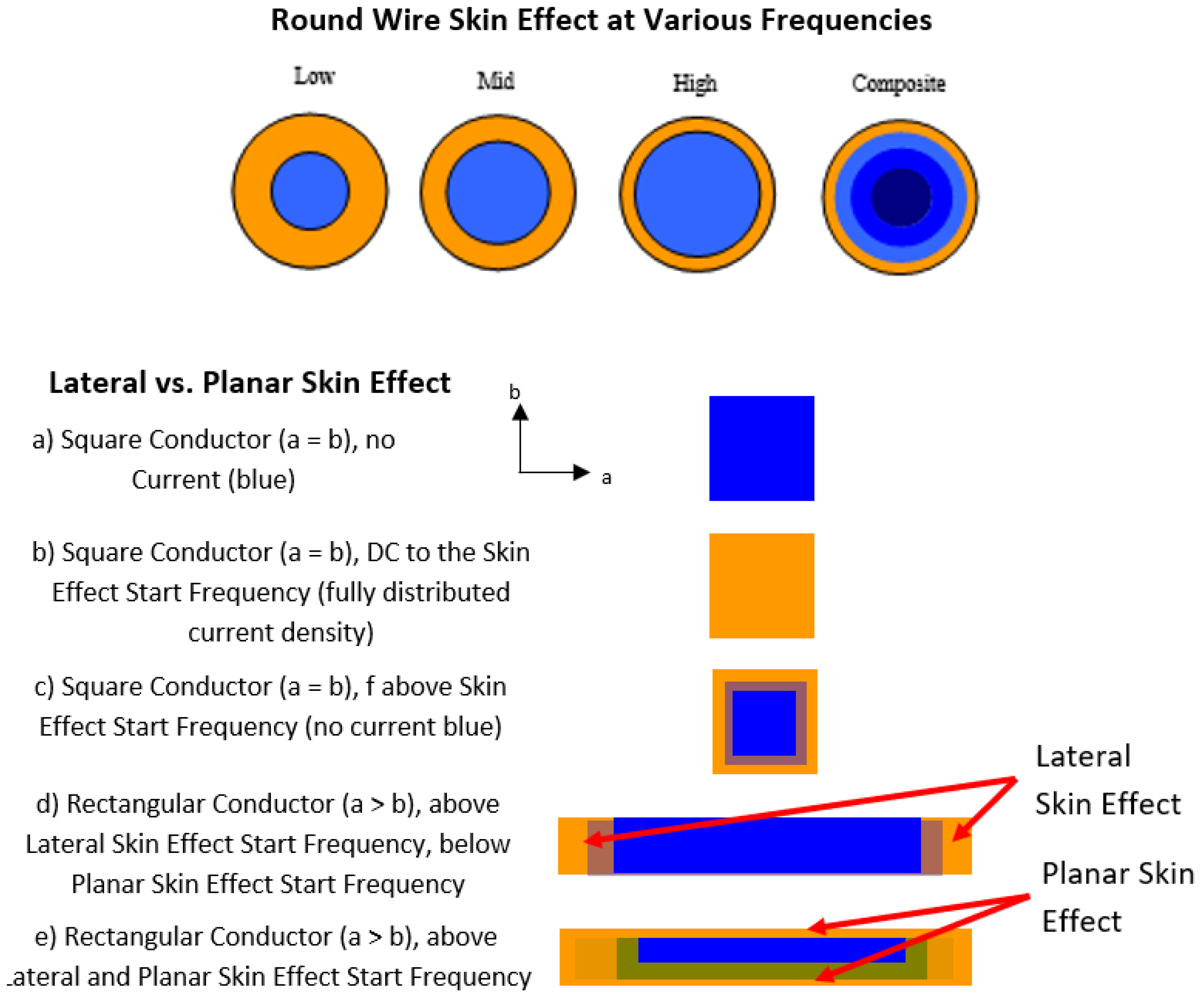
Figure 2.
Proposed electric and magnetic chain transduction in and around a conducting section. Internal electrons interacting with the dynamic elemental charge-photon population associated with current are proposed to transduce magnetic chain loops, while surface-associated electrons interacting with accumulated static elemental charge photons are proposed to transduce outward-extending electric chains. In an unintended electromagnetic structure, the relative prominence of these processes depends on local current, voltage, surface accumulation, geometry, frequency, and boundary conditions. Adapted from Figure 82, “Magnetic and Electric Chain Distributions of an Antenna Section,” in Photony Foundations Martin (2022).
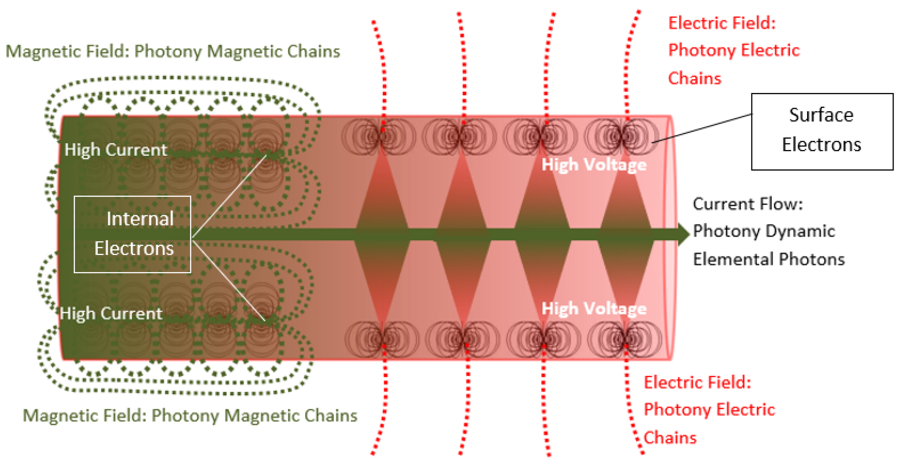

Table 1.
Conventional and proposed Photony interpretation of the four principal electromagnetic coupling mechanisms.
Table 1.
Conventional and proposed Photony interpretation of the four principal electromagnetic coupling mechanisms.
| Mechanism | Primary conventional driver | Important geometry | Proposed Photony interpretation |
|---|---|---|---|
| Conductive | Shared current and impedance | Connected conductors and return structures | Dynamic elemental charge-photon transport and redistribution through a shared conductive structure |
| Capacitive | Voltage and | Facing area, spacing, dielectric geometry | Surface accumulation and electric-chain interaction between source and victim surfaces |
| Inductive | Current and | Loop area, linkage, spacing | Internal-electron magnetic transduction and interaction between current-associated magnetic structures |
| Radiative | Distributed time-varying charge and current | Electrical length, orientation, resonance, surrounding region | Release and outward propagation of organized electric and magnetic structures followed by reception at the victim |
Disclaimer/Publisher’s Note: The statements, opinions and data contained in all publications are solely those of the individual author(s) and contributor(s) and not of MDPI and/or the editor(s). MDPI and/or the editor(s) disclaim responsibility for any injury to people or property resulting from any ideas, methods, instructions or products referred to in the content. |
© 2026 by the authors. Licensee MDPI, Basel, Switzerland. This article is an open access article distributed under the terms and conditions of the Creative Commons Attribution (CC BY) license (http://creativecommons.org/licenses/by/4.0/).
Copyright: This open access article is published under a Creative Commons CC BY 4.0 license, which permit the free download, distribution, and reuse, provided that the author and preprint are cited in any reuse.