

Submitted:
07 September 2026
Posted:
09 September 2026
You are already at the latest version
Abstract
Antennas are conventionally described through time-varying currents and charges, standing-wave distributions, near and far electromagnetic fields, impedance, radiation resistance, and Poynting-vector energy transport. These formulations accurately predict antenna behavior, but they do not necessarily provide an intuitive structural account of how electromagnetic energy is organized along a conductor and subsequently released into surrounding space. This article develops a complementary physical interpretation of intended antenna operation within the Beyond Field-Line Descriptions framework. Conventional antenna and electromagnetic theory are retained as the quantitative foundation, while the proposed Photony interpretation treats the antenna as a spatially distributed electron-transduction system. Regions of relatively high current are associated predominantly with magnetic structuring through internal electrons, whereas regions of relatively high voltage are associated predominantly with electric structuring through surface-associated electrons. During each half-cycle, changing voltage and current conditions produce growth, reduction, reversal, and pinch-off of the corresponding electric and magnetic chains. The resulting structures are proposed to separate progressively from the transducing electron population and propagate outward as organized electromagnetic energy. Particular attention is given to the standing-wave distribution along a dipole antenna, the distinct timing of electric and magnetic pinch-off, the transition from source-coupled structuring to outward energy transport, and the relationship between the proposed chain interpretation and the conventional Poynting-vector description. The framework is intended as a structural interpretation of established antenna behavior rather than a replacement for conventional antenna equations.
Keywords:
intended antennas
; dipole antenna
; electromagnetic energy transport
; standing waves
; electron transduction
; electric structuring
; magnetic structuring
; Poynting vector
; radiation
; Photony
1. Introduction
An intended antenna is a deliberately structured transition between guided electrical excitation and outward electromagnetic energy transport. Conventional antenna theory describes this transition through current and charge distributions, standing waves, radiation resistance, impedance, near and far fields, and the electromagnetic power carried away from the antenna [1,2,3]. These descriptions are quantitatively successful and form the engineering basis for antenna design. The remaining question addressed here is interpretive: what physical sequence might underlie the conversion of alternating electrical excitation on a conductor into propagating electromagnetic energy?
The preceding article in the Beyond Field-Line Descriptions series treated basic AC operation as repeated electromagnetic organization involving complementary electric structuring and magnetic structuring. Electric structuring was associated primarily with voltage and surface-associated electrons, while magnetic structuring was associated primarily with current and internal electrons. Alternating operation was interpreted as a recurring sequence of transduction, growth, reduction, reversal, and renewed transduction. The present article extends that framework from a general AC conductor to a structure specifically designed to release electromagnetic energy into the surrounding region.
A dipole antenna provides a particularly useful example because its standing-wave voltage and current distributions separate the locations of maximum electric and magnetic activity along the conductor. In conventional antenna theory, current is greatest near the central feed region of an approximately half-wave dipole and falls toward the ends, while voltage exhibits the complementary distribution. The precise distributions depend on antenna length, geometry, feed conditions, and surrounding environment [1]. This spatial separation provides a direct basis for examining how the proposed electron-transduction mechanism varies along the antenna.
Within the Photony interpretation, high-current regions contain windsock-aligned internal electrons that transduce dynamic elemental charge photons into magnetic chain loops, while high-voltage surface regions contain surface-associated electrons that transduce elemental charge photons into outward-extending electric chains [4]. The antenna is therefore treated not as a uniform radiating object but as a spatially distributed transduction structure whose local electric and magnetic behavior changes with the standing-wave pattern. The underlying source remains the same alternating electromagnetic excitation, but different portions of the antenna preferentially support different forms of structuring during a given stage of the cycle.
The half-cycle structure is especially important. As the applied voltage and current evolve, the corresponding electric and magnetic chains grow and reduce. Voltage reversal produces an electric-chain pinch-off condition, whereas current reversal produces a magnetic-chain pinch-off condition. Because voltage and current are generally not maximal or minimal at the same time along a resonant antenna, the two forms of pinch-off need not occur simultaneously. Photony proposes that the resulting finite electric and magnetic structures extend outward in successive half-cycle groupings rather than remaining permanently attached to the conductor [4].
The objective of this article is to examine that process in detail while retaining conventional antenna theory as the quantitative constraint. The analysis begins with the established current, voltage, standing-wave, and field description of a dipole antenna. It then develops the proposed electron-mediated electric and magnetic structuring along the antenna, examines the distinct roles of high-current and high-voltage regions, and considers how repeated reduction and pinch-off may relate to the release of electromagnetic energy from the source region. The resulting interpretation is then compared with the conventional Poynting-vector description of energy transport and with the established distinction between near-field storage and far-field radiation.
2. Conventional Electromagnetic Description of an Intended Antenna
An intended antenna is deliberately shaped and excited so that electrical energy supplied by a source is converted into outward electromagnetic radiation. Conventional antenna theory describes this process using time-varying charge and current distributions, standing-wave behavior, impedance, near and far electromagnetic fields, radiation resistance, and electromagnetic power flow [1,2,3]. These descriptions provide the quantitative foundation for antenna design and remain fully applicable in the present work.
The role of this section is therefore not to replace established antenna theory, but to identify the conventional relationships that the proposed Beyond Field-Line interpretation must reproduce. Particular attention is given to the spatial variation of current and voltage along a dipole antenna, the distinction between reactive and radiative fields, and the conventional description of electromagnetic energy transport away from the source.
2.1. The Dipole Antenna as a Distributed AC Structure
A center-fed dipole antenna is one of the simplest structures in which the transition from alternating electrical excitation to electromagnetic radiation can be examined. Unlike a lumped circuit element, an antenna cannot generally be treated as having the same voltage and current everywhere along its length. At radio frequencies, the finite propagation time and wavelength produce spatially varying current and charge distributions along the conductor [1,3].
For a thin, approximately half-wave dipole of total length L, with the feed point located at the center, the current distribution is commonly approximated by a standing-wave-like form. For a resonant thin dipole, a useful idealized representation is
where z is measured from the center of the antenna, is the approximate maximum current, and the free-space wavenumber is
For an approximately half-wave resonant dipole,
Equations (1)–(3) describe the idealized standing-wave current behavior of an approximately half-wave dipole. The current is greatest near the feed point and decreases toward the conductor ends, approaching zero at the ends in the thin-wire approximation [1]. This spatial current distribution is one of the defining characteristics of the antenna.
The corresponding charge and voltage distributions are approximately complementary. Regions in which current is relatively small can support comparatively large charge accumulation and electric potential variation, while regions near a current maximum generally exhibit smaller voltage magnitude. Thus, an antenna contains simultaneously distributed high-current and high-voltage regions rather than behaving as a single lumped voltage-current pair.
This distinction becomes central to the proposed interpretation developed later in this article because current-associated regions and voltage-associated regions are assigned different electron-mediated structural roles.
2.2. Standing-Wave Voltage and Current Relationships
The standing-wave character of an antenna reflects the interaction of traveling electromagnetic disturbances along the conductor with the antenna boundaries. Energy supplied at the feed point propagates along the conducting structure, and the open ends impose boundary conditions that produce reflected components. The superposition of forward and reflected behavior produces spatial distributions commonly described in terms of standing current and voltage waves [3].
In an idealized half-wave dipole, the current distribution has a maximum near the center and minima near the ends. The voltage distribution behaves approximately oppositely, with relatively low voltage near the center and relatively high voltage toward the ends.
The qualitative relationship can therefore be summarized as
and
These relationships are not exact point-by-point inverses in every practical antenna. The actual distributions depend on conductor diameter, geometry, feed arrangement, nearby materials, antenna loading, and frequency [1]. Nevertheless, the high-current central region and high-voltage end regions of a resonant dipole provide a useful first-order physical picture.
The spatial separation of these regions is particularly important because electromagnetic radiation is not produced by a single localized current element acting independently. The full distributed charge-current configuration contributes to the resulting electromagnetic field.
2.3. Time-Varying Charge and Current as Electromagnetic Sources
In conventional electrodynamics, charge density and current density are the sources of electromagnetic fields. Maxwell’s equations express these relationships as
and
Equations (4)–(7) provide the conventional field constraints for the antenna. For an antenna driven by an alternating source, both the charge distribution and the current distribution vary continuously with time. The resulting electric and magnetic fields therefore also vary with time and extend beyond the conductor into the surrounding region [2,5].
It is important, however, not to interpret Equations (6) and (7) as requiring a simple sequential statement that a changing electric field physically creates a magnetic field and that a changing magnetic field then creates an electric field. The complete time-dependent solution is determined by the common charge and current sources together with the electromagnetic boundary conditions. Jefimenko emphasized this point by showing that time-dependent electric and magnetic fields can be expressed directly in terms of retarded charge and current distributions [6].
This distinction is useful for the present article because the proposed Beyond Field-Line interpretation likewise treats electric and magnetic structuring as complementary responses of one electromagnetic system rather than as an endlessly self-generating sequence in which one field is physically transformed into the other.
2.4. Near-Field and Far-Field Regions
The electromagnetic environment surrounding an antenna is commonly divided into near-field and far-field regions. These regions are not separated by a single sharp physical boundary, but they exhibit different dominant behaviors [1].
Near the antenna, reactive electric and magnetic energy can remain strongly associated with the source. Energy may be stored temporarily and returned during later portions of the AC cycle. The electric and magnetic field components can have complicated spatial relationships, and their relative magnitudes and phases depend strongly on position.
At sufficiently large distance from the antenna, the radiation field dominates. In the far field, the electric and magnetic fields are approximately transverse to the direction of propagation and to each other:
Both are also approximately perpendicular to the propagation direction.
Their magnitudes are related by the intrinsic impedance of free space,
so that in the radiation zone,
The far-field amplitudes decrease approximately as
while the corresponding time-averaged power density decreases approximately as
2.5. Poynting Energy Transport
The conventional description of electromagnetic energy transport is given by the Poynting vector,
Equation (13) defines the electromagnetic energy-flux vector , with units of power per unit area.
Poynting’s theorem expresses local energy conservation as
where the electromagnetic energy density in a linear medium is
Equations (14) and (15) provide the conventional local conservation framework for electromagnetic energy transport [2,7].
For an antenna, this conservation relation is especially important because it shows that energy supplied by the source is not adequately described as merely traveling mechanically through the conductor with drifting electrons. Instead, electromagnetic energy occupies the surrounding field and can flow through the region around the conductors before becoming predominantly outward directed in the radiation zone.
In the far field of a radiating antenna, the time-averaged Poynting vector points predominantly away from the source. The total radiated power may be obtained by integrating the outward energy flux over a closed surface surrounding the antenna:
Equation (16) provides a direct quantitative measure of energy that has left the source region as electromagnetic radiation.
2.6. Reactive Energy and Radiated Energy
Not all electromagnetic energy surrounding an antenna is radiated permanently away from it. Some energy is stored temporarily in the electric and magnetic fields near the antenna and is subsequently returned to the source or exchanged with other portions of the structure. This behavior is analogous to reactive energy exchange in capacitors and inductors, but in an antenna the storage is spatially distributed [1,3].
It is therefore useful to distinguish conceptually between
and
The distinction does not imply that near-field and far-field processes are independent. Rather, they are different spatial manifestations of one time-dependent electromagnetic solution.
In conventional antenna theory, radiation resistance provides a circuit-level representation of the power carried away by electromagnetic radiation. If an antenna has radiation resistance , the average radiated power can be represented in terms of the feed current as
provided the current and resistance are defined consistently at the antenna feed point.
Equation (17) provides the circuit-level representation of radiated power. Radiation resistance is not a physical resistor that converts electrical energy directly into heat. It is an equivalent circuit quantity representing electromagnetic power transferred away from the antenna.
2.7. The Conventional Half-Cycle Picture
For a sinusoidally excited antenna, the distributed current and voltage change continuously through every cycle. During one half-cycle, charge accumulates with one polarity and current flows with one direction. During the succeeding half-cycle, both reverse.
Because voltage and current distributions are generally displaced in both space and time, their extrema and zero crossings need not occur simultaneously at the same location. Near a voltage maximum, the local current may be relatively small. Near a current maximum, the local voltage may be relatively small. As the standing-wave pattern evolves, electric and magnetic energy storage also changes.
The important conventional result is that antenna radiation is produced by a continuously time-dependent distributed electromagnetic system. Charge, current, electric field, magnetic field, stored energy, and outward energy flux all evolve together under the constraints of Maxwell’s equations and the antenna geometry.
The source material underlying the proposed Photony interpretation makes particular use of this half-cycle structure. It describes a dipole as containing alternating high-current and high-voltage regions, with current-associated and voltage-associated behavior changing through each half-cycle. It further proposes that voltage reversal and current reversal correspond to distinct electric and magnetic pinch-off events rather than a single simultaneous field reversal [4].
2.8. Conventional Constraints on the Proposed Interpretation
Any proposed structural interpretation of antenna radiation must remain consistent with several established results.
First, the antenna is a distributed structure whose current and voltage vary with position and time. Second, time-dependent charge and current distributions are the conventional sources of the electromagnetic field. Third, reactive electromagnetic energy can be stored near the antenna and returned, while radiated energy produces a net outward Poynting flux. Fourth, the far-field electric and magnetic components become approximately transverse and maintain the free-space impedance relationship expressed by Equation (10). Fifth, total radiated power must remain consistent with the electromagnetic energy flux obtained from Equation (16) and with established antenna quantities such as radiation resistance in Equation (17).
The Beyond Field-Line interpretation developed in the following sections does not alter these relationships. Instead, it asks whether the observed spatial and temporal behavior of an intended antenna can be given a more explicit structural interpretation in terms of electron-mediated electric structuring, magnetic structuring, chain reduction, reversal, and eventual release from the source region.
3. Standing-Wave Voltage and Current Structure
The conventional description developed in Section 2 establishes that an intended antenna is a distributed AC structure rather than a lumped element. This distinction becomes especially important for a resonant dipole because current, charge accumulation, and electric potential do not have the same spatial dependence along the conductor. The resulting standing-wave pattern provides the spatial framework for the electric structuring and magnetic structuring developed in the following sections.
3.1. Current Distribution Along a Resonant Dipole
For a thin center-fed dipole, the idealized current distribution introduced in Equation (1) can be extended explicitly into time dependence. For sinusoidal excitation, a useful first-order representation is
where is the approximate peak feed current, , L is the dipole length, and corresponds to the center feed point.
For an approximately resonant half-wave dipole,
so the current magnitude is greatest near the center and approaches zero toward the two open ends [1]. Equation (18) therefore describes both a spatial distribution and a temporal oscillation. The current at each position changes through the AC cycle, but the relative spatial envelope remains approximately standing-wave-like under steady sinusoidal excitation.
At the feed point,
whereas near the idealized conductor ends,
3.2. Charge Accumulation and the Complementary Electric Distribution
Current cannot terminate at the open ends of a dipole without an accompanying time-dependent redistribution of charge. The conventional continuity equation requires
For a thin-wire antenna, the same relationship may be represented approximately in one dimension using linear charge density :
Equation (23) shows that a spatial change in current is necessarily associated with changing charge accumulation. Where the current distribution decreases strongly with position, charge density changes correspondingly with time.
For the standing-wave current represented by Equation (18), the charge distribution is displaced in time from the current distribution. In an idealized sinusoidal representation, the charge density may be written schematically as
where represents the spatial charge envelope. The precise form depends on antenna geometry and boundary conditions, but its magnitude becomes comparatively large toward the open ends where current approaches zero [1,2].
The important relationship is therefore not merely that current and charge occupy different positions along the antenna. Their temporal extrema are also displaced. When current at a given high-current region is near an extremum, the rate of charge accumulation is correspondingly different from its value near a current zero crossing.
This distributed relationship provides the conventional basis for the high-current and high-voltage regions used throughout the remainder of this article.
3.3. Effective Voltage Distribution
Unlike the voltage between two conductors of an ideal transmission line, a unique local “voltage along an antenna” must be treated carefully because the surrounding electromagnetic field is fully three-dimensional. Nevertheless, antenna theory and engineering practice commonly use an effective standing-wave voltage description to represent the complementary electric behavior of a resonant antenna [1,3].
For the present physical discussion, an idealized voltage-like distribution may be represented schematically as
where increases toward regions of stronger charge accumulation and electric potential difference.
For an approximately half-wave dipole, this leads to the familiar qualitative pattern
and
Equation (25) is not intended to impose a transmission-line voltage definition on the antenna. It is a convenient representation of the spatial and temporal electric behavior associated with charge accumulation and potential variation.
This qualification is important because the proposed electric structuring developed later in the article must ultimately correspond to the physical electric field and surface-charge distribution, not merely to a circuit-style voltage label.
3.4. Current and Voltage Extrema are Complementary
The standing-wave distributions divide the dipole into regions with different electromagnetic roles. Near the feed region, current magnitude is high and the conventional magnetic field surrounding the conductor is correspondingly strong. Toward the conductor ends, current decreases while charge accumulation and electric-field intensity become increasingly important.
The approximate spatial complementarity may be written as
while
Equations (26) and (27) do not assert that electric and magnetic fields exist exclusively in separate portions of the antenna. Both field components are present throughout the electromagnetic system. Rather, the equations identify regions in which one form of activity becomes comparatively prominent.
This distinction is particularly useful for the Beyond Field-Line interpretation. The proposed framework does not require one portion of the antenna to be purely electric and another purely magnetic. Instead, it proposes that the relative dominance of surface-associated electric transduction and internal-electron magnetic transduction varies along the antenna in accordance with the established current and charge distributions.
3.5. Temporal Evolution Through One Cycle
The spatial standing-wave pattern must also be understood as a time-dependent process. Consider a representative sinusoidal cycle beginning at a current maximum in the central region. From Equation (18), the central current can be represented as
A complementary effective voltage-like quantity may be represented as
for the idealized standing-wave interpretation being used here.
Equations (28) and (29) illustrate the quarter-cycle displacement between representative current-dominant and charge-dominant conditions. This provides four useful stages for discussing the electromagnetic structure of the antenna.
At the first representative stage,
the center current is near a positive maximum while the complementary voltage-like quantity is near a zero crossing. Magnetic activity associated with the high-current region is therefore comparatively strong.
One quarter-cycle later,
the representative current passes through zero while charge accumulation and the corresponding electric condition approach an extremum.
At
the current reaches its opposite extremum, establishing the reversed current condition.
Finally, at
the current again approaches zero while the electric condition reaches its opposite extremum.
The cycle then repeats.
These representative stages should not be interpreted as four isolated states. The electromagnetic system evolves continuously between them. Their purpose is to identify the characteristic times at which current-dominant and charge-dominant behavior can be compared.
3.6. Separate Current and Voltage Reversals
The distinction between current and voltage behavior is especially important at reversal. A current reversal occurs when the current passes through zero and changes direction. A voltage or charge-polarity reversal occurs at a different stage of the idealized resonant cycle.
Thus,
identifies a current reversal, whereas an electric polarity reversal may be represented schematically by
Equations (34) and (35) identify distinct temporal events. This distinction will become central to the proposed chain interpretation because magnetic-chain reduction and reversal are associated primarily with the current condition, while electric-chain reduction and reversal are associated primarily with the electric potential and surface-charge condition.
The source treatment in Photony Foundations makes this distinction explicitly. It describes time gaps between electric chain structures as arising from voltage polarity reversals and separate time gaps between magnetic chain structures as arising from current polarity reversals [4].
3.7. Standing Waves and Intended Radiation
A standing-wave distribution on the antenna should not be confused with an absence of outward energy transport. The standing pattern describes the spatial variation of current and charge on the antenna structure, while radiation describes the net electromagnetic energy that leaves the source region.
The antenna therefore supports both a source-associated standing distribution and outward-propagating electromagnetic energy. The two descriptions refer to different aspects of the same driven system.
This distinction may be summarized as
The source continuously supplies energy. Some electromagnetic energy participates in reactive storage and return near the antenna, while some produces a nonzero outward time-averaged Poynting flux and is radiated.
For an intended antenna operating efficiently near resonance, the standing-wave distribution is therefore not merely a consequence of reflection. It is also part of the spatial organization that establishes where current, charge accumulation, electric field, and magnetic field are most strongly developed.
3.8. Spatial Basis for Electric and Magnetic Structuring
The central result of this section is that a resonant dipole provides a spatially and temporally differentiated electromagnetic environment.
The conventional relationships may be summarized as
and
Within the proposed Photony framework, these conventional distributions acquire a more explicit structural interpretation. Photony Foundations proposes that high-current portions of an antenna contain windsock-aligned internal electrons that transduce dynamic elemental charge photons into magnetic chain loops, while high-voltage portions of the conductor surface contain face-aligned surface electrons that transduce elemental charge photons into outward-extending electric chains [4].
The same source further proposes that the electron population undergoes an end-over-end x-spin response at the frequency of the conducted signal, allowing the electron orientation to reverse as the alternating excitation changes from one half-cycle to the next [4].
The standing-wave antenna can therefore be viewed, within the proposed framework, as a distributed electromagnetic transduction structure. Different regions of the same conductor preferentially support electric structuring or magnetic structuring according to the local voltage, charge, and current conditions. The next section develops the electron-transduction mechanism underlying that proposed spatial differentiation.
4. Electron Transduction Along the Antenna
Section 3 established that a resonant dipole contains spatially differentiated regions of relatively high current and relatively high charge or effective voltage. Within the proposed Photony framework, these regions are not interpreted as passive locations at which conventional field quantities merely happen to be larger. Instead, they are proposed to contain electron populations that perform different transduction roles according to the local electromagnetic condition [4].
The antenna is therefore treated as a distributed electron-mediated transduction structure. Internal electrons in high-current regions predominantly participate in magnetic structuring, while surface-associated electrons in high-voltage regions predominantly participate in electric structuring. These processes occur simultaneously within one electromagnetic organization, but their relative strength varies with position along the antenna and with time during the AC cycle.
4.1. Electrons as Transducers Rather than Energy Sources
Within the Photony model, the electron is proposed to act as a transducer and regulator of elemental charge photons. The electron does not create the electromagnetic energy that appears in electric or magnetic chains. Instead, incoming dynamic elemental charge photons provide the energy population, while the electron organizes that population into chain structures [4].
The basic distinction can be written schematically as
The supplied electromagnetic energy must remain consistent with conventional power and energy conservation. At the antenna feed point, the instantaneous electrical power supplied to the antenna is
and the time-averaged input power is
Therefore, any proposed microscopic transduction process must remain constrained by Equations (38) and (39). Chain formation cannot represent additional energy beyond that supplied to the antenna. Rather, the proposed chains are intended to be the physical organization of electromagnetic energy already represented by the conventional descriptions of voltage, current, field, and Poynting.
4.2. Internal and Surface Electron Populations
The spatially varying standing-wave pattern gives different electron populations different dominant roles.
In high-current portions of the antenna, dynamic elemental charge photons are proposed to flow through windsock-aligned internal electrons. These electrons transduce the elemental charge photons into closed magnetic chain loops extending around the conductor [4].
The proposed correspondence is
In high-voltage portions of the antenna, surface-associated electrons are proposed to orient according to the local electric condition and transduce elemental charge photons into outward-extending electric chains [4]. The corresponding qualitative relationship is as follows.
Equations (40) and (41) do not imply that the antenna is divided into completely magnetic and completely electric zones. Both forms of electromagnetic behavior coexist throughout the structure. The equations instead describe the proposed dominant transduction tendency associated with the local standing-wave condition.
Figure 1 provides the basic structural picture for the electron-transduction model used in this article. The conductor cross-section contains both internal and surface-associated electron populations, but the proposed dominant role of each population differs. Dynamic elemental charge photons moving through the conductor encounter internal electrons that are aligned by the current-associated condition. These electrons are proposed to transduce the elemental charge photons into closed magnetic chain loops. At the surface of the conductor, surface-associated electrons respond predominantly to the local electric condition and are proposed to transduce elemental charge photons into outward-extending electric chains [4].
The figure is particularly useful for the antenna problem because the standing-wave distributions developed in Section 3 naturally create regions in which these two transduction processes have different relative prominence. Near the central high-current region of a resonant half-wave dipole, internal-electron magnetic transduction is expected to dominate. Toward the higher-voltage regions near the conductor ends, surface-associated electric transduction becomes increasingly important. The antenna can therefore be interpreted as a spatially distributed transduction structure in which the relative balance between magnetic structuring and electric structuring changes continuously along the conductor.
The two processes shown in Figure 1 should not be interpreted as independent electromagnetic systems. Both are components of one electromagnetic organization and are driven by the same alternating excitation. Their distinction lies in the electron population involved, the local current or voltage condition, and the geometry of the chain structure produced.
Within the proposed model, the electron is also not the source of the electromagnetic energy. The dynamic elemental charge photons constitute the underlying energy population, while the electrons act as transducers and regulators that organize those photons into magnetic or electric chains [4]. This distinction will be used in the following subsections to examine magnetic transduction in high-current regions and electric transduction in high-voltage regions separately.
4.3. Magnetic Transduction in High-Current Regions
For the approximately half-wave dipole considered here, the central region near the feed point contains the largest current magnitude. Conventional electromagnetics associates this current with a strong circumferential magnetic field around the conductor.
Within Photony, the same region is interpreted as one in which internal free electrons are strongly engaged in magnetic-chain transduction. Dynamic elemental charge photons passing through these aligned electrons are proposed to become interlinked into magnetic chain loops extending around the antenna conductor [4].
The conventional magnetic energy density is
Because the local magnetic field magnitude increases with current, the proposed magnetic-chain population must reproduce the same increase in stored magnetic energy. Thus,
4.4. Electric Transduction in High-Voltage Regions
Toward the ends of a resonant dipole, the current magnitude decreases, while the charge accumulation and the electric potential variation become comparatively large. Therefore, these regions support strong electric behavior.
Within the Photony interpretation, surface-associated electrons in these high-voltage regions transduce elemental charge photons into electric chains that extend outward from the conductor surface [4]. The chains are proposed to be predominantly single-ended structures associated with the surface electron population.
The conventional electric energy density is
The proposed correspondence is therefore
4.5. Spatially Distributed Transduction
The antenna should therefore not be pictured as having one single transduction point. The electron-mediated process is distributed along the entire conducting structure.
Figure 2 extends the local conductor model of Figure 1 to the scale of the dipole antenna. Near the feed point, the conducted signal contains a relatively high density of dynamic elemental charge photons moving longitudinally through the antenna. Internal electrons in this region are proposed to transduce a substantial portion of this population into magnetic chain loops, producing the strong magnetic structure associated with the current maximum [4].
As the dynamic elemental charge photons progress away from the feed region toward the ends of the dipole, their distribution does not remain uniformly confined within the conductor. Within the Photony interpretation, the elemental charge photons naturally tend increasingly to encounter the conductor surface. Upon reaching the surface, dynamic elemental charge photons are proposed to convert into static elemental charge photons and accumulate there. This redistribution reduces the population that continues as a longitudinal current while increasing the surface-associated charge condition represented macroscopically by voltage [4].
The decline of current and magnetic structuring away from the feed region is therefore linked, in the proposed model, to the increasing transfer of the elemental charge-photon population toward the conductor surface. The same redistribution that diminishes the current-associated population supplies the static elemental charge photons from which surface electrons transduce electric chains. Consequently, the standing-wave transition from the high-current central region toward the high-voltage regions of the dipole is interpreted as a progressive change in the dominant form of electromagnetic structuring rather than as two unrelated field distributions.
The proposed sequence along either half of the dipole may therefore be summarized as
Equation (46) provides a structural interpretation of the complementary standing-wave distributions developed in Section 3. Near the feed, magnetic structuring is strongest because the longitudinal dynamic elemental charge-photon population is greatest. Toward the antenna ends, this population progressively diminishes as surface accumulation increases, resulting in greater electric structuring. The high-current and high-voltage regions shown in Figure 2 are therefore connected stages of a distributed electromagnetic organization.
At a given instant, some regions can be strongly current dominated, some strongly voltage dominated, and others intermediate. The transduction tendency can therefore be represented schematically as a position- and time-dependent balance,
where denotes the proposed contribution associated predominantly with the conductor’s surface electron electric transduction and denotes the contribution associated predominantly with the conductor’s internal electron magnetic transduction.
Equation (47) is deliberately qualitative. It does not introduce a new measured antenna parameter. Its purpose is to emphasize that the proposed electromagnetic organization varies both spatially and temporally along the antenna.
Near the center of a resonant half-wave dipole,
whereas toward the ends,
4.6. Intrinsic c-Spin and Extrinsic x-Spin
The proposed electron mechanism requires two distinct rotational behaviors.
The intrinsic c-spin of the electron is part of its persistent toroidal structure. By contrast, x-spin is an externally driven end-over-end reorientation associated with alternating excitation [4]. In an antenna driven at an angular frequency , it is proposed that the electron population undergoes this extrinsic reorientation in response to the alternating signal.
The excitation frequency is
and the corresponding AC period is
Within the proposed model, the x-spin response follows this alternating cycle. The electron therefore changes its orientation from one half-cycle to the next, while retaining its intrinsic c-spin.
The two rotational behaviors must not be conflated:
whereas
This distinction becomes particularly important when transduction changes to reduction and when the electron prepares to transduce the succeeding chain structure.
Figure 3 makes explicit the distinction between the persistent internal gamma ray rotation of the electron and its AC-driven change in orientation. The intrinsic c-spin remains part of the electron structure, while the x-spin changes the orientation of the electron relative to the alternating flow of elemental charge photons. In the proposed antenna mechanism, this distinction is essential because the electron must repeatedly pass between transduction, reduction, and renewed transduction without losing its intrinsic rotational structure.
The x-spin is therefore not proposed as the source of the intrinsic spin of the electron. It is an additional externally driven motion superimposed on that structure. Chapter 8 describes this axial end-over-end rotation as occurring in response to alternating voltage and current conditions and associates it with the repeated formation of electromagnetic chains [4].
4.7. Chain Rotation During Transduction
Photony further proposes that the chain formed through electron transduction is not rotationally static. The transduced chain rotates at the rate established by the electron’s intrinsic c-spin [4].
During transduction, the newly formed chain therefore acquires the rotational sense associated with the electron’s present orientation. Schematically,
Equation (52) adds a rotational property to the proposed chain structure. The electron is not merely interlinking elemental charge photons geometrically. It also establishes the rotational behavior of the resulting chain.
This feature becomes important when the local voltage or current begins to decline. The previously formed chain must then undergo reduction before the electron completes the x-spin transition required for the next orientation.
4.8. Transduction, Reverse-Spin Reduction, and Electron Reorientation
When the supporting AC quantity begins to decrease, net chain growth cannot continue indefinitely. The previously transduced structure must instead undergo reduction.
The sequence proposed here is important. The electron does not first complete its x-spin flip and then reduce the previous chain. Instead, a transition interval occurs before the flip is complete.
During transduction, the chain rotates in the sense established by the electron’s present c-spin orientation. When the AC condition changes from increasing to decreasing support, the existing chain becomes reduced. During this reduction interval, the chain rotates in the opposite direction while its links are progressively removed.
Only after reduction of the prior chain is complete does the electron complete its x-spin reorientation. The reoriented electron is then prepared to begin transduction for the succeeding portion of the AC cycle.
The sequence is therefore
Equation (53) distinguishes three physically different processes: chain construction, reverse-spin chain reduction, and electron reorientation.
The reverse-spin interval is therefore not a consequence of an electron that has already flipped. It is a transitional part of the reduction process that occurs before the x-spin reorientation is complete.
4.9. Transduction Follows the Local AC Condition
Because current and electric potential vary with both position and time, the local transduction process also varies with both position and time.
A region near the center of the dipole may undergo strong magnetic-chain transduction during an interval in which the local current magnitude is increasing. During the same interval, an end region may be in a different stage of electric-chain growth or reduction according to its local charge and voltage condition.
The antenna therefore cannot be described within this model as if all electrons simultaneously perform the same transduction operation. Instead,
where Equation (54) is qualitative and identifies the principal dependencies rather than defining a new constitutive law.
This distributed behavior is consistent with the conventional observation that the antenna possesses a spatial standing-wave pattern. The proposed addition is that the spatial variation corresponds to locally different electron-mediated chain processes.
4.10. Electron Transduction and Electromagnetic Organization
The full antenna may therefore be interpreted as a coordinated electromagnetic organization built from complementary local processes.
High-current regions favor magnetic structuring through internal electrons. High-voltage regions favor electric structuring through surface-associated electrons. Intermediate regions contain both behaviors in varying proportions. As the standing-wave pattern evolves over time, each region passes through transduction, reduction, reversal, and renewed transduction intervals.
The proposed relationship may be summarized as
Equation (55) provides the structural bridge between the standing-wave description of Section 3 and the subsequent treatment of electric and magnetic structure.
The importance of this interpretation is that radiation is not introduced as an unexplained final step occurring after the conventional current has already been established. The proposed mechanism begins with the same electrons and elemental charge-photon population that support the AC behavior of the conductor and follows their organization along the antenna as the electromagnetic structure develops.
The next section examines electric structuring specifically, with emphasis on surface-associated electrons, high-voltage regions, outward-extending electric chains, and their evolution through the antenna cycle.
5. Electric and Magnetic Structuring Along the Dipole
The standing-wave description developed in Section 3 and the electron-transduction model developed in Section 4 together provide a spatial interpretation of the dipole antenna. The central high-current region and the higher-voltage regions toward the ends are not treated as unrelated electromagnetic features. Within the proposed Photony framework, they are different stages in the redistribution and restructuring of the same underlying elemental charge-photon population.
Near the antenna feed, the longitudinal flow of dynamic elemental charge photons is greatest. Internal electrons in this region are therefore proposed to participate strongly in magnetic-chain transduction, producing the magnetic structuring associated with the current maximum. As the elemental charge photons move away from the feed and toward the ends of the dipole, an increasing portion of that population is proposed to encounter the conductor surface. Upon reaching the surface, the dynamic elemental charge photons convert into static elemental charge photons and accumulate there, increasing the local voltage condition and supporting surface-electron electric-chain transduction [4].
The result is a continuous spatial transition in the dominant form of electromagnetic structuring along the antenna.
5.1. From High Current to High Voltage
For an approximately half-wave dipole, the conventional current distribution is greatest near the center and decreases toward the open ends. The effective voltage and surface-charge distribution behave approximately oppositely. Section 3 described this behavior conventionally. The Photony interpretation adds a proposed microscopic sequence linking the two distributions.
Near the feed region,
and the local population of dynamic elemental charge photons moving longitudinally through the conductor is correspondingly large in the proposed model. These photons pass through windsock-aligned internal electrons, which transduce a portion of the population into magnetic chain loops.
Moving outward along either arm of the dipole, the current amplitude decreases. Within Photony, this decline is interpreted partly as a consequence of the dynamic elemental charge photons increasingly encountering the conductor surface rather than continuing exclusively as longitudinal current. The surface therefore becomes an increasingly important destination for the electromagnetic energy population.
The proposed progression can be represented as
Equation (57) is a qualitative structural interpretation of the established decline in antenna current away from the feed. It does not replace the conventional standing-wave current solution.
5.2. Conversion at the Conductor Surface
When the proposed dynamic elemental charge photons encounter the conductor surface, they do not continue outward in the same dynamic form. Within the Photony model, they convert into static elemental charge photons and accumulate at the surface [4].
The conversion may be represented schematically as
As the static elemental charge-photon population grows, the local surface charge and voltage condition increase. Surface-associated electrons are then proposed to transduce this static population into electric chains extending outward from the conductor.
The corresponding sequence is
5.3. Reduction of Magnetic Structuring Away from the Feed
The decline of current away from the feed is accompanied conventionally by a decline in the strength of the associated magnetic field. Within the Photony interpretation, the same trend corresponds to a decrease in the local dominance of magnetic-chain transduction.
This relationship may be summarized as
The important point is that this decline is not interpreted simply as magnetic energy disappearing. The same distributed electromagnetic population is being reorganized spatially. As the longitudinal dynamic elemental charge-photon population decreases, surface accumulation and electric structuring increase.
Thus, the magnetic and electric distributions are connected through redistribution rather than treated as independent spatial profiles.
5.4. Growth of Electric Structuring Toward the Dipole Ends
Toward the open ends of the dipole, conventional current approaches a minimum while charge accumulation and electric potential become comparatively large. In the proposed model, these regions contain a larger surface-associated population of static elemental charge photons.
The resulting electric structuring can be represented as
Equation (61) identifies the qualitative correspondence between the conventional charge-voltage distribution and the proposed electric-chain population.
The electric chains are proposed to extend outward from surface-associated electrons in the high-voltage regions. Their growth therefore represents not merely an increase in an abstract field-line density but an increase in the proposed organized structure associated with the local electric energy.
5.5. One Continuous Electromagnetic Redistribution
The standing-wave pattern may therefore be interpreted as a continuous redistribution between current-associated and surface-associated electromagnetic structuring.
A useful summary is provided below.
Equation (62) should not be interpreted as a one-way conversion of magnetic chains directly into electric chains. The proposed electric and magnetic structures remain physically distinct. The connection lies instead in the redistribution of the underlying elemental charge-photon population and in the changing electron population through which that energy is transduced.
This distinction is important. Internal electrons predominantly transduce magnetic chains from the dynamic charge-photon flow, while surface-associated electrons predominantly transduce electric chains from the static charge-photon population accumulated at the conductor boundary. The standing-wave distribution determines where each process becomes relatively more important.
Figure 4 brings together the spatial relationships developed throughout this section. The current maximum near the feed is associated with the greatest longitudinal flow of dynamic elemental charge photons. Consequently, this region supports the strongest current-associated magnetic structuring. Moving away from the feed along either antenna arm, the current decreases as the proposed elemental charge-photon population increasingly encounters the conductor surface.
Within the Photony interpretation, a surface encounter changes the role of the elemental charge photon. A dynamic elemental charge photon that participates in the longitudinal current is proposed to convert into a static elemental charge photon when it reaches and becomes confined at the conductor surface. Accumulation of this static population produces the increasing surface-charge and voltage condition toward the antenna ends. The Surface-associated electrons then transduce this population into outward-extending electric chains [4].
The standing-wave pattern therefore has a proposed physical continuity that is not evident from simply plotting current and voltage separately. The decline of current toward the antenna ends and the simultaneous growth of the voltage condition are interpreted as related consequences of redistribution of the elemental charge-photon population. Magnetic structuring is strongest where dynamic longitudinal flow is greatest, whereas electric structuring becomes strongest where surface conversion and accumulation are greatest.
Importantly, Figure 4 does not imply that magnetic chains are converted directly to electric chains. The proposed conversion occurs at the level of the elemental charge-photon population. Dynamic elemental charge photons that participate in current increasingly reach the surface and become static elemental charge photons. Internal electrons predominantly transduce the former population into magnetic chains, whereas surface-associated electrons predominantly transduce the latter population into electric chains. Electric and magnetic structuring therefore remain distinct while being coupled through redistribution of their common underlying electromagnetic energy population.
5.6. Spatial Complementarity Along the Dipole
The result is a spatially complementary antenna structure.
Near the center,
where and denote the relative prominence of magnetic and electric structuring, respectively.
Toward the ends,
Equations (63) and (64) are qualitative and do not introduce new measurable antenna parameters. Their purpose is to express the proposed change in dominant structuring along the conductor.
Neither relation implies that the complementary contribution vanishes. Magnetic and electric behavior coexist throughout the antenna, but their relative strengths vary with local current, charge, and voltage conditions.
5.7. Temporal Reversal of the Spatial Pattern
The spatial pattern described above is not static. During the succeeding half-cycle, the current direction reverses, and the surface charge polarity reverses. The same spatial regions remain associated with current maxima and voltage maxima in the standing-wave sense, but the directional orientation of the corresponding electromagnetic structuring changes.
Thus, the antenna does not simply maintain a fixed magnetic center and electric ends. Rather, the local magnetic-chain circulation and electric-chain polarity repeatedly reverse as the AC excitation evolves.
The spatial distribution is therefore combined with a temporal sequence,
Equation (65) links the spatial antenna model to the AC transduction cycle developed in the preceding article of this series.
5.8. Transition Toward Electromagnetic Release
The spatial redistribution developed in this section establishes the antenna-scale electromagnetic organization from which radiation can emerge. Near the feed, current-associated magnetic structuring is strongest. Toward the ends, surface-associated electric structuring becomes increasingly prominent. Throughout the structure, both forms evolve continuously with alternating excitation.
The next stage is not simply the further growth of these structures. As local voltage and current pass through their respective extrema and approach reversal, the previously transduced chains must be reduced and separated from the electron populations that formed them. The proposed transition from attached structuring to released electromagnetic structure therefore depends on the reduction and pinch-off processes associated with the voltage and current reversals.
The next section examines those half-cycle reduction and pinch-off events and their proposed role in converting antenna-associated electromagnetic structuring into outward-propagating electromagnetic energy.
6. Half-Cycle Reduction, Pinch-Off, and Electromagnetic Release
Section 4 and Section 5 established how electric and magnetic structuring develops along the dipole as current and voltage vary in space and time. The next question is how those structures cease to remain continuously attached to the electron populations that transduced them. Within the proposed Photony framework, this transition occurs through reduction followed by distinct magnetic and electric pinch-off events associated with current and voltage reversal [4].
The process is not treated as a simultaneous collapse of one undifferentiated electromagnetic field. Magnetic structuring follows primarily from current and internal-electron transduction, while electric structuring follows primarily from voltage, surface charge, and surface-electron transduction. Their reversal conditions therefore occur at different stages of the antenna cycle.
6.1. Reduction Precedes Reversal
A chain that has grown during increasing excitation does not remain at its maximum extent after the supporting current or voltage begins to decrease. Within Photony, the decreasing portion of the cycle is interpreted as a period of net reduction.
For magnetic structuring,
while for electric structuring,
Equations (66) and (67) describe the proposed structural response as the corresponding conventional field energy decreases. Reduction is therefore not equivalent to breakdown or dissipation. It is part of the normal reversible or nearly reversible AC process, in which the previously established chain structure is progressively unlinked as the supporting electromagnetic condition weakens.
The electron reorientation described in Section 4 is coupled to this transition. During the reduction interval, it is proposed that the existing chain rotates in the reverse sense while the links are removed. The electron does not complete its x-spin flip until reduction of the prior chain is complete. The sequence established previously is therefore directly relevant to antenna release:
Equation (68) provides a finite structural transition between one orientation of the antenna field and the next.
6.2. Magnetic Pinch-Off at Current Reversal
The magnetic chain population is associated primarily with the current condition. As the current magnitude decreases toward zero, the magnetic structuring is reduced. When the current reaches its reversal condition,
the previous magnetic circulation can no longer be maintained in its earlier orientation.
Photony proposes that this condition produces magnetic-chain pinch-off [4]. The previously transduced magnetic structure becomes separated from the internal electron population that established it, while the electrons complete their reorientation for the succeeding current direction.
The magnetic sequence may therefore be summarized as
The term “pinch-off” is used here to distinguish the termination of the previously attached chain structure from the subsequent transduction of a new structure with reversed circulation. It is therefore a structural event associated with reversal, not simply another name for a zero value of magnetic field amplitude.
6.3. Electric Pinch-Off at Voltage Reversal
Electric structuring follows a different timing condition. Surface-associated electric chains are supported by surface charge and electric potential. As the voltage magnitude declines, the electric-chain population undergoes reduction. In the electric reversal condition,
the prior electric orientation can no longer remain attached in the same polarity.
Photony proposes that this produces electric-chain pinch-off [4]. Surface electrons then complete the reorientation required for the succeeding polarity and begin transducing a new electric structure.
The corresponding sequence is
6.4. Electric and Magnetic Pinch-Off are Temporally Distinct
In the idealized standing-wave description of the resonant dipole used in Section 3, representative current-dominant and voltage-dominant conditions are separated by approximately one quarter-cycle. Consequently, the magnetic and electric pinch-off events are also temporally separated.
For a sinusoidal cycle with the representative quadrature relation used earlier,
Equation (73) represents the idealized temporal separation between the corresponding current- and voltage-associated reversal conditions. Real antenna behavior depends on geometry, loading, feed conditions, and local phase, so the exact timing should not be interpreted as universally fixed at every point on every antenna [1,3].
The central structural point is more general: magnetic-chain pinch-off is tied to current reversal, whereas electric-chain pinch-off is tied to electric-polarity reversal. They need not occur simultaneously.
Figure 5 makes the temporal distinction between magnetic and electric release explicit. The magnetic portion of the cycle is governed primarily by the current condition. As current magnitude decreases, magnetic-chain organization is reduced until the current reversal terminates the previous circulation. The electric portion follows the corresponding voltage and surface-charge condition. As the voltage magnitude decreases toward its zero crossing, the previous electric structure is reduced until the polarity reversal terminates the prior electric orientation.
The two events are therefore associated with different electron populations and different points in the AC cycle. Internal electrons participate predominantly in the magnetic process, while surface-associated electrons participate predominantly in the electric process. The separate timing shown in Figure 5 is consistent with the quarter-cycle displacement between representative current-dominant and voltage-dominant conditions developed in Equation (73).
The figure also clarifies the meaning of pinch-off in the proposed model. Pinch-off is not the initial cause of chain reduction. Reduction has already occurred while the magnitude of the supporting current or voltage is decreasing. Pinch-off marks the completion of the previous attached structure at the reversal condition, after which the electron completes its reorientation and regenerated transduction can establish the succeeding structure.
Thus, the progression is
Equation (74) emphasizes that reduction, pinch-off, and electron reorientation are sequential parts of the proposed release process rather than interchangeable descriptions of the same event.
This distinction is important because it prevents the radiated electromagnetic structure from being interpreted as one field configuration that simply detaches all at once. The proposed release occurs through a sequence of complementary electric and magnetic events.
6.5. From Attached Structuring to Released Structure
Before pinch-off, the proposed chains remain directly associated with the electron populations that are transducing or reducing them. After pinch-off, the previously established chain segment is no longer continuously dependent on continued transduction by the same electrons.
This transition may be represented schematically as
Equation (75) is the central proposed mechanism by which antenna-associated electromagnetic structure begins to become an outward-propagating electromagnetic structure.
The term “released” does not mean that the structure is created without an energy source. The energy remains constrained by the power supplied to the antenna and by conventional electromagnetic conservation. Rather, release means that a previously source-coupled chain structure has reached a stage at which it is no longer being maintained through continuous attachment to the same transducing electron population.
6.6. Successive Half-Cycle Structures
Because the process repeats continuously, an intended antenna produces successive electromagnetic structures associated with successive portions of the AC waveform. Chapter 8 of Photony Foundations describes separate time gaps between electric structures caused by voltage reversal and between magnetic structures caused by current reversal, with the resulting electric and magnetic chain loops extending outward in successive half-cycle groupings [4].
The repeated sequence may therefore be summarized as
Equation (76) applies separately to the electric and magnetic components, with their respective timing determined by voltage and current.
The outward electromagnetic structure is therefore proposed to consist of a continuing succession of finite electric and magnetic organizations rather than a permanently attached field that simply changes amplitude everywhere at once.
6.7. Relation to Conventional Radiation
The proposed pinch-off mechanism must remain consistent with the conventional result that an antenna produces an outward electromagnetic energy flux. In conventional theory, radiation is described by the far-field components of and and by the outward time-averaged Poynting vector,
Equation (77) remains the quantitative measure of radiated electromagnetic energy flux. The Photony interpretation does not replace this relation. Instead, it proposes that chain reduction and pinch-off provide a physical structural mechanism underlying the transition from antenna-associated electric and magnetic structuring to outward-propagating electromagnetic organization.
The Poynting vector itself is not a chain and is not treated as the physical object being released. Rather, it describes the direction and rate of electromagnetic energy transport associated with the evolving electric and magnetic structures.
6.8. Release as a Distributed Antenna Process
Pinch-off should also not be interpreted as occurring at one singular point on the antenna. Because the antenna contains spatially distributed current, charge, and voltage conditions, reduction and reversal also occur within a distributed structure.
In regions of high-current, the magnetic component is especially prominent. In high-voltage regions, the electric component is especially prominent. As the cycle progresses, these regions undergo their corresponding reductions and reversals, producing a spatially coordinated sequence of release events across the antenna.
Thus,
Equation (78) provides the bridge between the local electron processes described above and the larger-scale propagation considered in the next section.
The next section examines how the successively released electric and magnetic structures are proposed to develop away from the antenna and how that interpretation relates to conventional near-field and far-field radiation.
7. Outward Electromagnetic Structure and Radiation
Section 6 described the proposed transition from source-coupled electric and magnetic structuring to released electromagnetic structure. The next question is how those released structures develop away from the antenna and how the proposed chain interpretation relates to the conventional distinction between near-field behavior and outward radiation.
Conventional antenna theory describes the field surrounding a dipole as a continuous time-dependent electromagnetic solution generated by the distributed charge and current on the antenna. Close to the conductor, reactive electric and magnetic energy can remain strongly coupled to the source and can be returned during later portions of the AC cycle. At larger distances, the radiative terms dominate, producing a net outward electromagnetic energy flux whose field amplitudes decrease approximately as and whose time-averaged power density decreases approximately as [1,2]. These conventional relationships remain the quantitative constraints on the interpretation developed here.
Within the proposed Photony framework, the transition from near-source structuring to radiation is interpreted as the outward development of successively released electric and magnetic chain structures. The essential distinction is between chains that remain directly coupled to transducing electron populations and structures that have completed reduction and pinch-off and can continue outward as part of the propagating electromagnetic organization [4].
7.1. Near-Source Electromagnetic Organization
Immediately surrounding the antenna, the proposed electric and magnetic structures remain strongly related to the distributed electron-transduction processes along the conductor. Magnetic structuring is strongest near the high-current regions, while electric structuring is strongest toward the high-voltage regions. These structures grow, reduce, and reverse in response to the local AC condition.
This near-source region is therefore not interpreted as containing only outward-radiating energy. Some electromagnetic structure remains temporarily coupled to the antenna and participates in the cycle of storage and return represented conventionally by reactive near-field energy.
The conventional local energy density is
and the corresponding energy flux is
Equations (79) and (80) remain the conventional measures of electromagnetic energy and energy transport. The proposed chain model adds a structural interpretation in which portions of that local energy are associated with electric and magnetic chain configurations that may remain source coupled for part of the cycle.
Thus, the near field contains both
and
The two should not be treated as sharply separated populations. Rather, the relative importance of reactive and radiative behavior changes continuously with distance and with the phase of the antenna excitation.
7.2. Successive Released Structures
The half-cycle mechanism developed in Section 6 produces repeated electric and magnetic release events. Because voltage reversal and current reversal occur at different stages of the AC cycle, the resulting released structures are also temporally ordered.
Chapter 8 of Photony Foundations describes the transmitted electromagnetic structure as successive orthogonal electric and magnetic chain loops, with time gaps associated with the voltage and current reversals that produce separate electric and magnetic pinch-off events [4]. The proposed sequence is therefore not one simultaneous detachment of a complete electromagnetic shell. Instead, it is a continuing series of complementary electric and magnetic structures produced through the repeating AC cycle.
A compact representation is
where and denote successive electric and magnetic-dominant structural intervals rather than independent electromagnetic waves.
Equation (81) is schematic. It does not imply that the conventional electric or magnetic field vanishes between the indicated stages. Instead, it represents the proposed sequence of dominant chain release events associated with alternating current and voltage conditions.
Figure 6 provides an antenna-scale view of the release sequence developed in Section 6. The electric and magnetic structures are shown to progress outward in successive half-cycle groupings, with the interruption of electric structuring associated with voltage reversal and the interruption of magnetic structuring associated with current reversal. The resulting spatial sequence therefore reflects the same temporal separation between electric and magnetic pinch-off described previously.
The figure also illustrates the proposed transition from source-coupled structuring to outward electromagnetic organization. Once the respective electric or magnetic structure has completed reduction and pinch-off, it is no longer maintained through continuous attachment to the same transducing electron population. Instead, it is proposed that the released structures continue outward as mutually orthogonal components of the propagating electromagnetic organization [4].
7.3. Orthogonal Electric and Magnetic Structuring
In the far-field limit of conventional electromagnetic radiation, the electric and magnetic fields are mutually transverse and also transverse to the direction of propagation. As introduced in Section 2,
with
The proposed Photony interpretation must reproduce this orthogonal organization.
Within that interpretation, released electric and magnetic chains are proposed to become orthogonally linked as the transmitted electromagnetic structure develops outward from the antenna [4]. Electric chain organization remains associated with the electric component, while magnetic-chain organization remains associated with the magnetic component. Therefore, their orthogonal relationship provides the proposed structural counterpart to the conventional transverse geometry and .
This should not be interpreted as a replacement for Maxwell’s equations. Equation (82) remains the measurable far-field relationship. The proposed chain description instead asks what physical organization might correspond to that measured orthogonality.
7.4. From Discrete Release Events to a Continuous Waveform
Although the proposed mechanism involves repeated reduction and pinch-off events, a receiving instrument generally observes a continuous sinusoidal or modulated electromagnetic waveform rather than a sequence of visibly separated structures.
There is no contradiction in this distinction. At radio frequencies, the cycle period is extremely short, and successive structures are generated continuously. Their spatial spacing is determined by the propagation speed and the excitation frequency.
For a propagation speed approximately equal to the local speed of light c in free space,
A half-cycle corresponds to a propagation distance
while a quarter-cycle corresponds to
Equations (85) and (86) provide the conventional spatial scales associated with the temporal sequence described earlier. Within the proposed model, the repeated electric and magnetic release events therefore form a continuously propagating electromagnetic organization whose spatial periodicity remains constrained by the conventional wavelength.
7.5. Outward Expansion and Geometric Spreading
As released electromagnetic structure propagates away from the antenna, it occupies an increasing transverse area. Conventional radiation theory expresses this behavior through the approximate far-field dependence
and
Within the Photony interpretation, these relations constrain how the proposed chain organization may spread spatially. The model cannot imply increasing chain-associated energy density with distance or any energy multiplication during propagation. Instead, the electromagnetic organization must expand while conserving the energy supplied by the source, apart from absorption, scattering, or other interactions with the surrounding medium.
The proposed chain picture therefore interprets the decrease in measured field amplitude as geometric dilution of the organized electromagnetic energy over increasing area, while the total outward energy flux integrated over an appropriate closed surface remains consistent with the radiated power,
Equation (89) remains the quantitative conservation requirement.
7.6. Reactive Return Versus Net Radiation
A useful distinction can now be made between two forms of electromagnetic behavior surrounding the antenna.
The first consists of structure that remains sufficiently coupled to the source to be reduced and returned during later portions of the AC cycle. This corresponds to conventional reactive energy storage.
The second consists of structure that has progressed through reduction and pinch-off into a configuration producing net outward energy transport. This corresponds to radiated energy.
The proposed distinction may be summarized as
Equation (90) is interpretive rather than a new quantitative boundary condition. Conventional antenna theory does not define one universal distance at which all reactive behavior ends and all radiation begins. The proposed structural interpretation should therefore likewise be understood as a gradual transition rather than an abrupt geometric surface.
7.7. Electromagnetic Release Does Not Require Field Self-Creation
The outward propagation described here also clarifies an important conceptual point introduced earlier in this article. Conventional Maxwell equations are sometimes described informally as if a changing electric field creates a magnetic field, which then creates another electric field, producing a self-sustaining sequence.
The present interpretation does not require this picture. The electric and magnetic components originate from the common distributed charge-current system and remain coupled parts of one electromagnetic organization. Within Photony, the corresponding electric and magnetic chains are likewise proposed to arise from complementary electron-transduction processes and to continue outward as an organized linked structure after release.
Thus, outward propagation is not interpreted as repeated creation of one field by the other. It is interpreted as continued propagation of an already organized electromagnetic structure whose electric and magnetic components remain mutually constrained.
7.8. Radiation as Continuation of Antenna Organization
The principal result of Section 5 through Section 7 can now be summarized compactly. Radiation is proposed to be the continuation of electromagnetic organization that begins within and on the antenna.
Near the feed, dynamic elemental charge-photon flow produces strong magnetic structuring through internal-electron transduction. Toward the antenna ends, increasing surface encounters convert a growing fraction of that population into static elemental charge photons, producing higher voltage and stronger electric structuring. Through each AC cycle, the resulting chain structures grow, undergo reverse-spin reduction, pinch off at their respective reversal conditions, and become part of the outward electromagnetic organization.
The overall sequence is therefore
Equation (91) summarizes the proposed structural interpretation of intended antenna operation. Every stage remains constrained by established antenna relations, including standing-wave current and voltage distributions, electromagnetic energy conservation, far-field orthogonality, wavelength-frequency relation, and Poynting energy flux.
The value of the proposed interpretation is therefore not that it changes the measurable equations of antenna radiation. Rather, it provides a continuous physical narrative connecting electron-scale transduction inside and on the conductor to the outward electromagnetic structure measured conventionally as antenna radiation.
8. Discussion
The interpretation developed in this article is intended to complement, rather than replace, conventional antenna theory. The established relationships for current and charge distribution, near- and far-field behavior, radiation resistance, wavelength, and Poynting energy transport remain the quantitative framework against which the proposed mechanism must be judged. The Photony contribution is instead structural: it proposes that the distributed current and voltage pattern of a dipole reflects different electron-mediated transduction processes involving dynamic and static elemental charge-photon populations.
Within this interpretation, the high-current region near the feed supports predominantly magnetic structuring through internal electrons, while increasing surface encounters toward the dipole ends convert dynamic elemental charge photons into static elemental charge photons and thereby support increasing voltage and electric structuring. The standing-wave pattern is therefore interpreted as a continuous redistribution of the underlying electromagnetic energy population rather than as two unrelated field distributions. The subsequent reduction, pinch-off, and outward development of electric and magnetic structures provide a proposed physical sequence that connects antenna excitation to radiation.
Several limitations remain. The present treatment does not derive antenna impedance, radiation resistance, gain, directivity, field amplitude, or radiation efficiency from first-principles chain dynamics. These quantities remain determined by conventional electromagnetic and antenna equations. Likewise, the proposed chain geometry and electron-transduction sequence have not yet been formulated as a complete predictive microscopic model capable of independently reproducing measured antenna characteristics.
The framework is therefore best regarded at this stage as a testable structural hypothesis. Useful future tests would seek observables that distinguish the proposed sequence of transduction, surface conversion, reduction, and temporally separated electric and magnetic pinch-off from conventional descriptions alone. Frequency-dependent current localization, surface charge evolution, phase-resolved near-field measurements, and time-resolved radiation from controlled dipole geometries may provide useful directions for such comparisons.
Frequency-dependent redistribution of current within the conductor, including conventional skin-effect localization and its proposed consequences for electron transduction, represents an important refinement of this picture but is beyond the scope of this article.
9. Conclusions
This article developed a structural interpretation of intended antenna operation within the Beyond Field-Line Descriptions framework. Conventional antenna theory remains the quantitative foundation, while Photony proposes that the standing-wave current and voltage distributions correspond to complementary electron-mediated magnetic and electric structuring.
In this interpretation, dynamic elemental charge photons support current and magnetic-chain transduction near high-current regions, while increasing surface encounters toward the dipole ends produce static elemental charge photon accumulation, higher voltage, and electric-chain transduction. Repeated reduction, reversal, and pinch-off then provide a proposed mechanism for the transition from antenna-associated structuring to outward electromagnetic radiation.
The model is presently interpretive rather than independently predictive, but it provides a continuous physical narrative linking electron transduction, standing-wave structure, and electromagnetic release in an intended antenna.
References
- Balanis, C.A. Antenna Theory: Analysis and Design, 4 ed.; John Wiley & Sons, 2016. [Google Scholar]
- Jackson, J.D. Classical Electrodynamics, 3 ed.; John Wiley & Sons, 1999. [Google Scholar]
- Pozar, D.M. Microwave Engineering, 4 ed.; John Wiley & Sons, 2012. [Google Scholar]
- Martin, F.L. Photony Found. 2022. [CrossRef]
- Griffiths, D.J. Introduction to Electrodynamics, 4 ed.; Cambridge University Press, 2017. [Google Scholar]
- Jefimenko, O.D. Electricity and Magnetism: An Introduction to the Theory of Electric and Magnetic Fields, 2 ed.; Electret Scientific Company, 1989. [Google Scholar]
- Poynting, J.H. On the Transfer of Energy in the Electromagnetic Field. Philos. Trans. R. Soc. Lond. 1884, 175, 343–361. [Google Scholar] [CrossRef]
Figure 1.
Proposed magnetic and electric chain transduction through different electron populations in and on a conductor. Internal free electrons are shown interacting with dynamic elemental charge photons and transducing them into closed magnetic chain loops associated with current and magnetic structuring. Surface-associated electrons are shown interacting with elemental charge photons at the conductor boundary and transducing outward-extending electric chains associated with surface charge, voltage, and electric structuring. The figure therefore illustrates two complementary transduction processes occurring within one electromagnetic organization. Adapted from Figure 58, “Magnetic and Electric Chain Transduction,” in Photony Foundations [4].
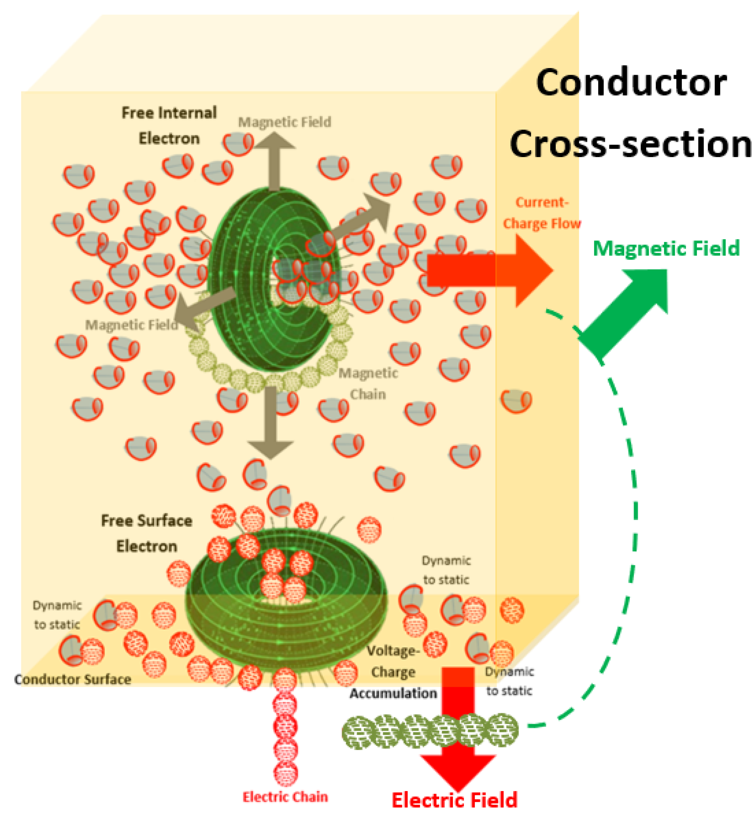
Figure 2.
Proposed spatial redistribution of electromagnetic structuring along a center-fed dipole antenna. Near the feed point, the relatively high longitudinal flow of dynamic elemental charge photons supports strong internal-electron transduction of magnetic chain loops. Toward the dipole ends, an increasing fraction of the dynamic elemental charge-photon population is proposed to encounter the conductor surface, convert to static elemental charge photons, and accumulate there, producing the higher-voltage condition from which surface-associated electrons transduce outward-extending electric chains. The figure therefore represents a continuous spatial transition from predominantly magnetic structuring near the high-current region to increasingly electric structuring toward the high-voltage regions [4].
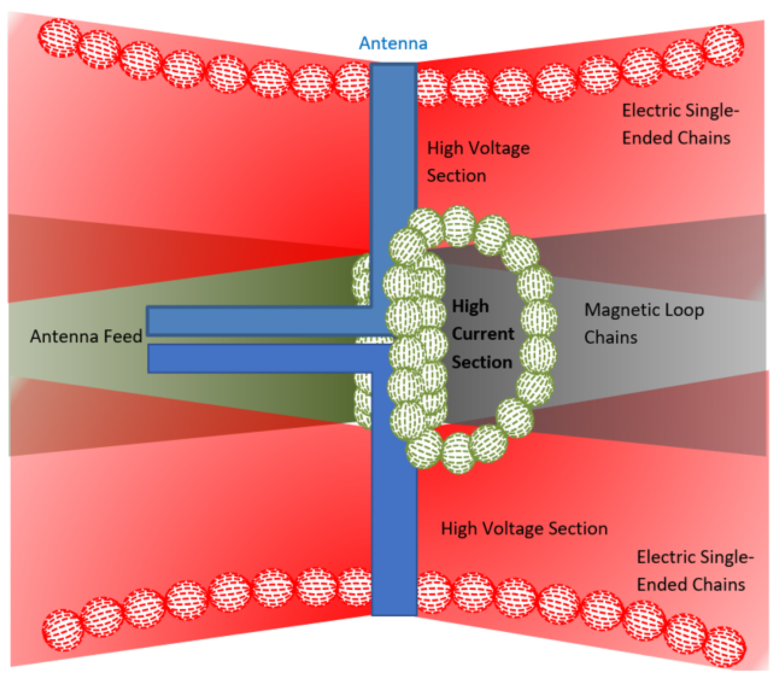
Figure 3.
Proposed AC-induced x-spin reorientation of the Photony electron. The electron retains its intrinsic c-spin while its toroidal orientation undergoes an externally driven end-over-end rotation in response to alternating excitation. The x-spin therefore changes the orientation through which elemental charge photons enter and leave the electron’s transduction region without replacing the intrinsic c-spin. This reorientation provides the proposed mechanism by which the electron can transition between successive transduction and reduction states during an AC cycle. Adapted from Figure 83, “Electron Tilt Axis (X-spin),” in Photony Foundations [4].
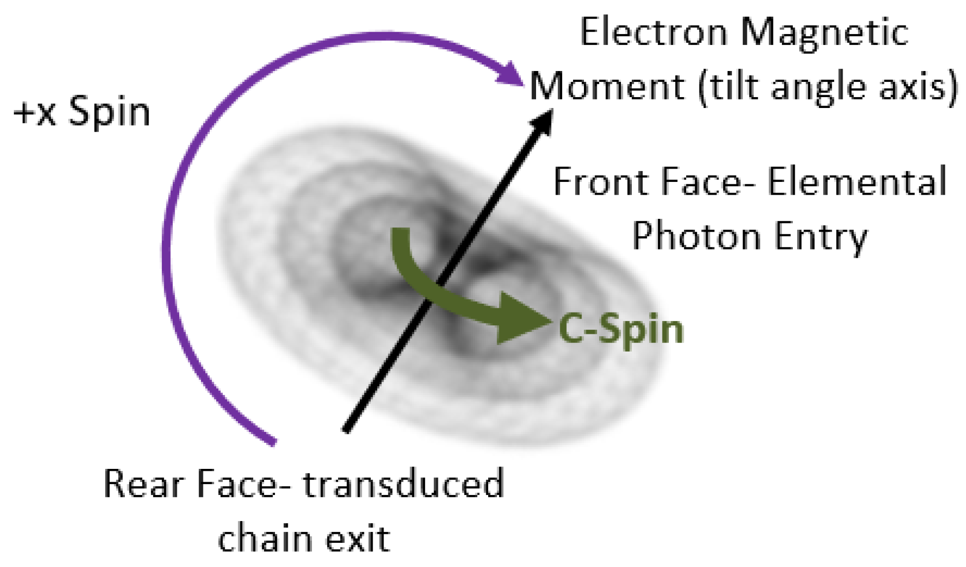
Figure 4.
Standing-wave snapshot of a center-fed dipole interpreted in terms of complementary electric and magnetic structuring. At the illustrated instant, the current magnitude is greatest near the center of the dipole and decreases toward the ends, while the electric potential is greatest toward the ends with opposite polarity on the two antenna arms. Within the proposed Photony interpretation, the high-current central region contains the greatest longitudinal population of dynamic elemental charge photons and therefore supports strong internal-electron transduction of magnetic chains. As the elemental charge photons progress toward the antenna ends, an increasing fraction is proposed to encounter the conductor surface, convert from dynamic to static elemental charge photons, and accumulate there. This surface accumulation increases the voltage condition and supplies the static elemental charge-photon population from which surface-associated electrons transduce electric chains. Adapted from Figure 87, “Snapshot of Dipole Standing Wave,” in Photony Foundations [4].
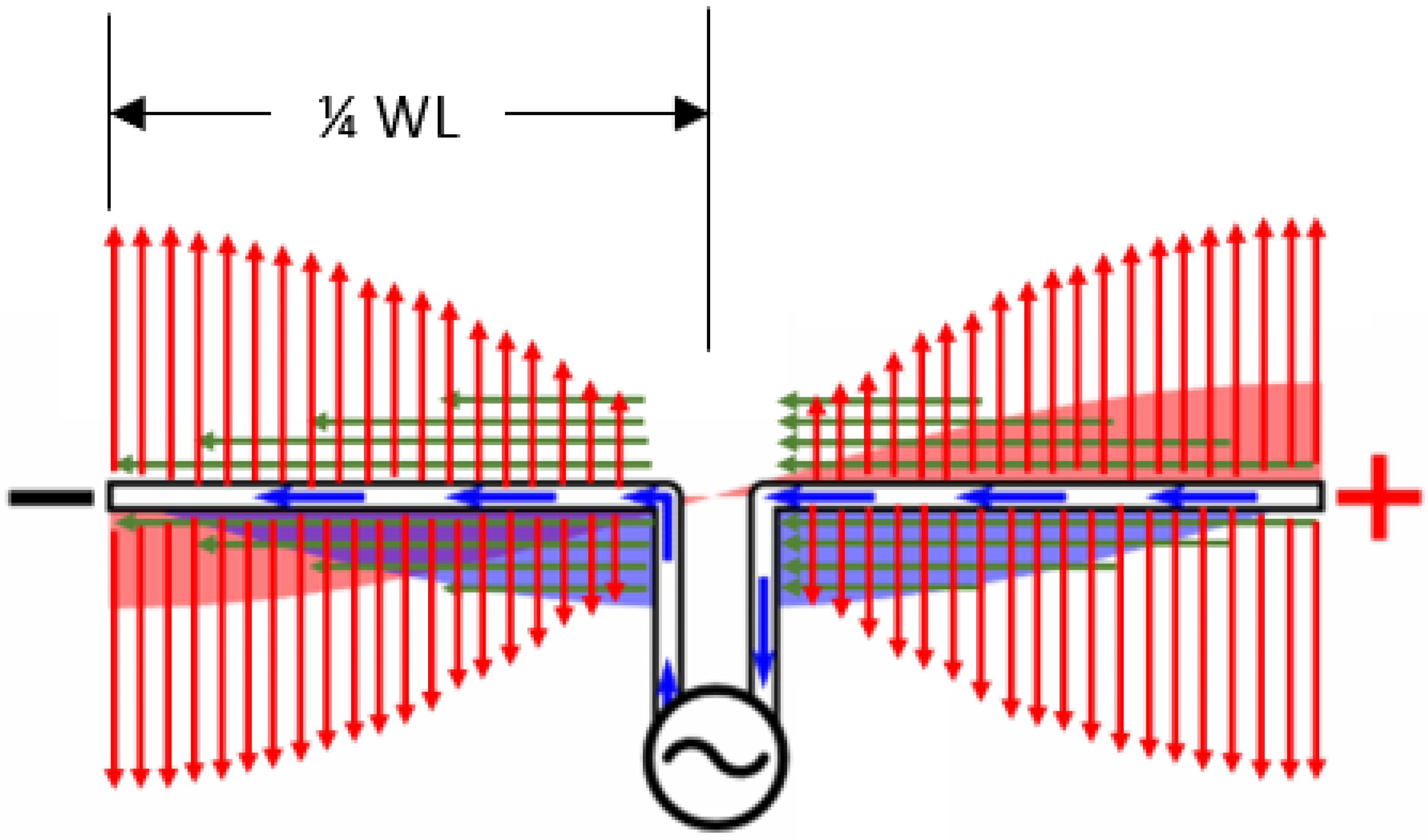
Figure 5.
Proposed magnetic and electric chain pinch-off during an AC cycle. Panel (a) illustrates magnetic-chain reduction and pinch-off associated with the current reversal condition. As the current approaches zero, the previously transduced magnetic structure is reduced and its prior circulation terminates before renewed magnetic transduction begins with opposite orientation. Panel (b) illustrates the corresponding electric-chain process associated with voltage reversal. As the surface-potential condition approaches zero and reverses polarity, the previous electric structure is reduced and pinched off before renewed electric transduction begins with opposite polarity. Because the current and voltage reversal conditions are temporally displaced in the resonant dipole, magnetic and electric pinch-off occur as distinct events rather than as one simultaneous electromagnetic detachment. Adapted from Figure 85 and 86, “Magnetic Chain Pinch-off” and “Electric Chain Pinch-off,” in Photony Foundations [4].
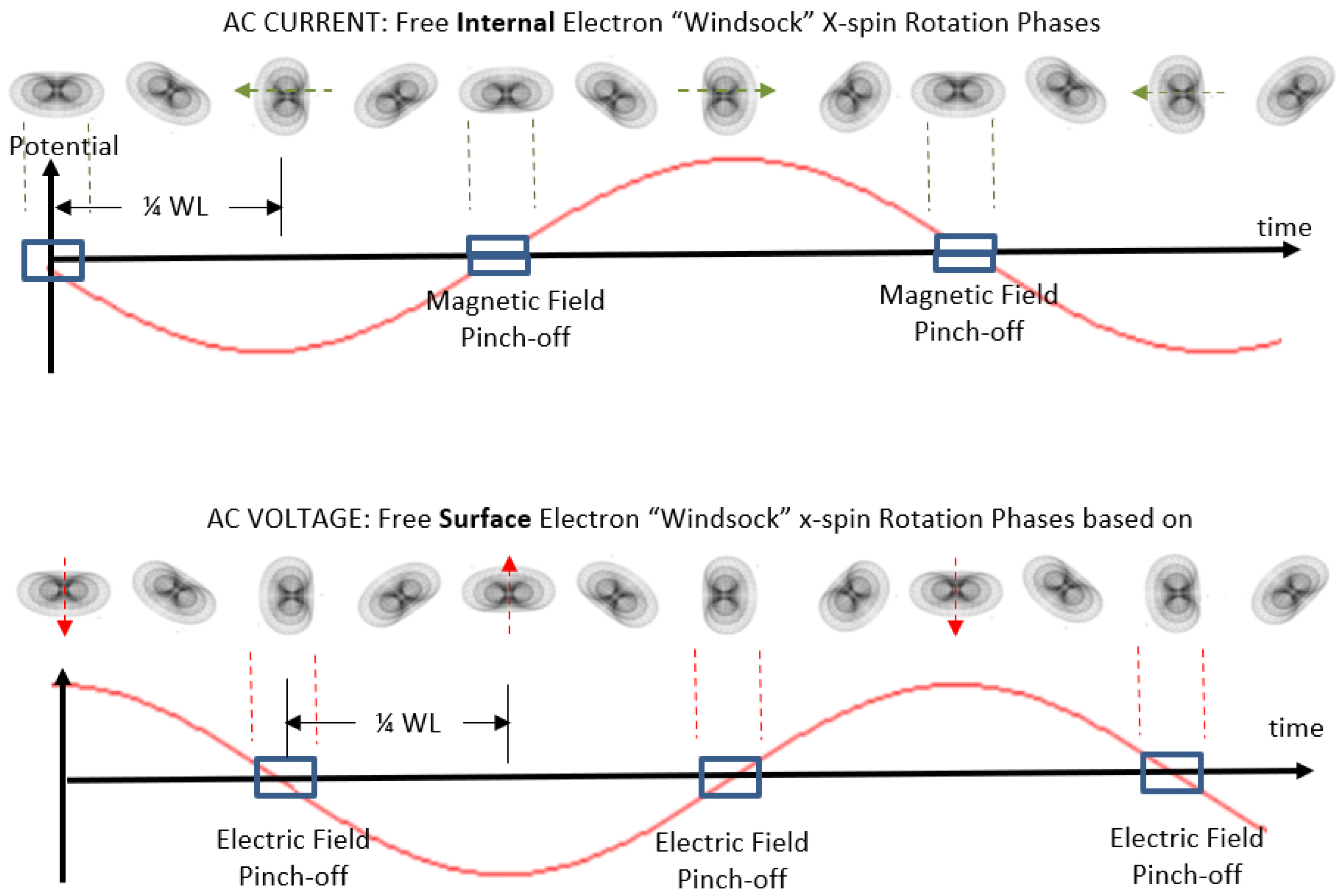
Figure 6.
Proposed outward development of orthogonal electric and magnetic chain structures over successive half-cycles of dipole excitation. Electric-chain structures are associated primarily with the voltage condition and undergo pinch-off at voltage reversal, while magnetic-chain structures are associated primarily with the current condition and undergo pinch-off at current reversal. Because these reversal conditions are temporally displaced, the released electromagnetic organization develops as an alternating sequence of electric- and magnetic-dominant structures rather than as a single simultaneous detachment. The successive structures are proposed to remain orthogonally linked as they propagate outward from the antenna. Adapted from Figure 97, “Orthogonal Pinched-off EM Loops in Half-cycles,” in Photony Foundations [4].
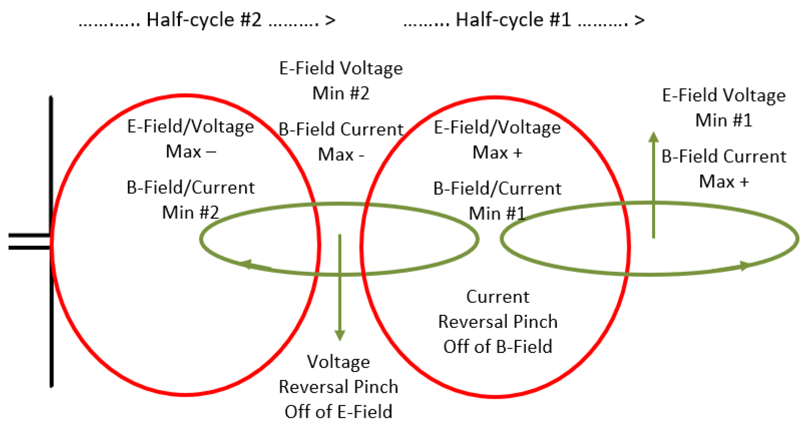
Disclaimer/Publisher’s Note: The statements, opinions and data contained in all publications are solely those of the individual author(s) and contributor(s) and not of MDPI and/or the editor(s). MDPI and/or the editor(s) disclaim responsibility for any injury to people or property resulting from any ideas, methods, instructions or products referred to in the content. |
© 2026 by the authors. Licensee MDPI, Basel, Switzerland. This article is an open access article distributed under the terms and conditions of the Creative Commons Attribution (CC BY) license (http://creativecommons.org/licenses/by/4.0/).
Copyright: This open access article is published under a Creative Commons CC BY 4.0 license, which permit the free download, distribution, and reuse, provided that the author and preprint are cited in any reuse.