

Submitted:
07 September 2026
Posted:
08 September 2026
You are already at the latest version
Abstract
Alternating-current systems are conventionally described through voltage, current, impedance, phase relationships, electric and magnetic fields, and electromagnetic energy storage. These formulations accurately predict AC behavior, but they do not always provide an intuitive physical account of how electric and magnetic structuring repeatedly grows, decreases, reverses, and rebuilds during each cycle. This article develops a complementary interpretation of that cyclic behavior within the Beyond Field-Line Descriptions framework. Conventional electromagnetic and circuit relations are retained as the quantitative foundation, while the proposed Photony interpretation assigns electrons an additional role as transducers and regulators of organized electromagnetic chains. Surface-associated electrons are proposed to participate predominantly in electric-chain organization associated with voltage and capacitive storage, whereas internal electrons are proposed to participate predominantly in magnetic-chain organization associated with current and inductive storage. Alternating excitation is therefore interpreted as a repeated sequence of transduction, growth, reduction, pinch-off, reversal, and renewed transduction. Particular attention is given to the distinction between electric and magnetic reversal conditions, the relationship between stored energy and the rate of change of voltage or current, and the different roles of surface and internal electron populations. The resulting framework does not alter established AC equations, but provides a structural narrative for the cyclic electric and magnetic behavior they describe.
Keywords:
alternating current
; electromagnetic energy transport
; electric fields
; magnetic fields
; Poynting vector
; electron transduction
; reactive power
; capacitive energy storage
; inductive energy storage
; skin effect
; phase relationships
; electromagnetic
; AC systems
; field-line descriptions
; Photony
1. Introduction
Alternating-current systems are among the most mature and extensively modeled technologies in electrical engineering. Their behavior is routinely described using voltage, current, impedance, reactance, phase, electric and magnetic fields, and energy storage in capacitive and inductive components. These tools provide accurate quantitative predictions across a wide range of practical systems. However, the physical interpretation of what occurs during one complete AC cycle can remain less intuitive than the circuit equations themselves. Conventional descriptions identify how voltage and current vary, how electric and magnetic energy are stored, and how reactive components exchange energy, but do not necessarily provide a detailed structural narrative for the repeated buildup, reduction, reversal, and rebuilding of electromagnetic organization.
This distinction becomes particularly important because alternating systems are not simply direct-current systems with periodically reversing current. During each cycle, electric and magnetic energy storage can rise and fall at different times, and the timing of those changes depends on the phase relationship between voltage and current. A capacitor stores energy predominantly in electric form, while an inductor stores energy predominantly in magnetic form. In reactive systems, energy may be supplied to a component during one portion of the cycle and returned during another. The AC cycle therefore contains a recurring sequence of energy organization and release that is only partially visible in time-averaged quantities such as root-mean-square voltage, current, and average power.
The present article develops a complementary interpretation of that sequence within the Beyond Field-Line Descriptions framework established in the preceding articles of this series. Rather than treating electric and magnetic field lines as independently existing physical objects, the framework interprets them as representations of organized electromagnetic structures. Within the proposed Photony model, those structures are formed from chains of elemental charge photons and are transduced and regulated through electron interactions Martin (2022). The conventional equations are retained, while the proposed interpretation seeks to describe a possible physical organization corresponding to the fields represented by those equations.
Electrons therefore occupy a central role in the present treatment. Photony distinguishes between the dominant behavior of electrons associated with conductor surfaces and those located within conductive material. Surface-associated electrons are proposed to transduce predominantly electric chains related to voltage and electric potential, while internal electrons are proposed to transduce predominantly magnetic chain loops associated with current Martin (2022). These two forms of organization are related, but they are not identical, and their maxima, minima, and reversal events need not occur at the same time.
Under alternating excitation, electron-mediated organization is not static. As voltage or current magnitude increases, the corresponding electric or magnetic structuring is proposed to grow through transduction. As the supporting quantity decreases, the previously established organization is proposed to undergo reduction. When voltage polarity or current direction reverses, the previously established chains are proposed to pinch off or terminate in their prior orientation, after which the new elemental charge photon chain structure is transduced with reversed direction or circulation Martin (2022). The resulting cycle may therefore be summarized conceptually as
This interpretation is especially useful for capacitive and inductive systems because their established energy relations provide direct quantitative constraints on any proposed microscopic mechanism. For an ideal capacitor,
so stored electric energy follows voltage magnitude. For an ideal inductor,
so stored magnetic energy follows current magnitude Griffiths (2017); Jackson (1999); Sadiku (2018). At the same time, capacitor current depends on , while inductor voltage depends on . The distinction between stored energy and the rate of change of that energy organization is therefore central to the present analysis.
The purpose of this article is to develop this electric-magnetic AC cycle systematically. Section 2 establishes the conventional foundation using sinusoidal voltage and current, instantaneous power, electric and magnetic energy storage, reactive exchange, and the timing of voltage and current reversal. Section 3 develops the proposed electron-transduction mechanism and the role of transduction, reduction, c-spin, x-spin, and chain pinch-off during one AC cycle. Section 4 and Section 5 then examine the electric and magnetic sides of that cycle separately, with particular emphasis on capacitive and inductive energy organization. The complementary but distinct nature of electric and magnetic structuring is summarized in the Conclusions.
The scope of this article is intentionally limited to the basic AC organization cycle. More detailed treatment of phase-coupled electromagnetic transport, conductor-surface localization, transmission structures, intended radiation, unintended antennas, electromagnetic compatibility, and signal integrity is reserved for subsequent articles in the Beyond Field-Line Descriptions series.
2. Conventional Energy Description of AC Systems
Alternating-current systems are conventionally described using voltage, current, impedance, phase, electric and magnetic fields, and electromagnetic power flow. These quantities provide highly successful engineering descriptions of AC behavior, but represent several aspects of the same physical process. Circuit theory describes relationships among terminals and interconnected components, while electromagnetic field theory describes how energy is stored and transported throughout the spatial regions associated with those components Griffiths (2017); Jackson (1999). A central objective of this article is to connect these descriptions more explicitly and then to examine their physical interpretation beyond conventional field-line representations.
An AC source periodically reverses the voltage polarity and current direction. For steady-state sinusoidal excitation, voltage and current may be represented as:
and
where and are peak voltage and current, is angular frequency, and is the phase difference between voltage and current. The instantaneous electrical power is:
which gives
This expression is particularly important for the present discussion because electromagnetic energy transfer in an AC system is not constant. Even under sinusoidal steady-state conditions, instantaneous power varies throughout the cycle. Depending on the load and phase relationship, energy may be transported toward a load during one portion of the cycle and returned toward the source during another.
Using root-mean square quantities, the conventional active power is
while reactive power is
The apparent power magnitude is
These quantities form the conventional basis for describing sinusoidal AC power flow IEE (2010). Active power represents the net transfer of energy that can ultimately be converted into heat, mechanical work, radiation, or other irreversible forms. Reactive power represents periodic energy exchange associated primarily with capacitive and inductive storage. Consequently, zero average real power does not imply that no energy moves. An ideal reactive element may repeatedly receive and return substantial energy during every cycle.
The distinction between net energy transport and alternating energy exchange is also emphasized in the Photony treatment of real and reactive power Martin (2022). However, the existence of reactive energy exchange itself is an established result of conventional AC theory and does not depend on the Photony interpretation.
2.1. Electric and Magnetic Energy Storage
Conventional electromagnetic theory associates stored energy with both electric and magnetic fields. For linear media, the electric energy density is
and the magnetic energy density is
The total electromagnetic energy density may therefore be written as
for the corresponding nondispersive linear case Griffiths (2017); Jackson (1999).
These contributions can vary continuously in an AC system. Their relative magnitudes and timing depend on circuit geometry, material properties, excitation frequency, and the phase relationship between voltage and current.
At the lumped-circuit level, the same behavior is represented through capacitive and inductive energy storage. The energy stored in an ideal capacitor is
while the energy stored in an ideal inductor is
A capacitor is therefore associated primarily with electric energy storage, while an inductor is associated primarily with magnetic energy storage Sadiku (2018).
For an ideal capacitor, current leads voltage by . Energy enters the capacitor as the magnitude of its voltage increases and returns to the surrounding circuit as the stored electric energy decreases. For an ideal inductor, voltage leads current by . Magnetic energy increases as current magnitude increases and is released as current magnitude decreases.
Within the Photony framework, these established forms of energy storage receive an additional proposed physical interpretation. Capacitive energy storage is associated with organized electric chains, while inductive energy storage is associated with magnetic chain organization. These chains are proposed to consist of interlinked elemental charge photons and to be transduced and regulated through electron interactions Martin (2022). The conventional energy relations are retained, while the proposed chain model seeks to describe the physical organization represented by the fields.
2.2. Power Reversal During an AC Cycle
For a purely resistive load, voltage and current are in phase, such that . Instantaneous power becomes:
which remains nonnegative throughout the cycle. Energy is continuously transferred toward the resistive load and ultimately converted into thermal or other forms.
For an ideal capacitor or inductor, however, instantaneous power alternates between positive and negative values. During intervals of positive instantaneous power, electromagnetic energy is supplied to the reactive element. During intervals of negative instantaneous power, stored energy is returned to the source or redistributed elsewhere within the network IEE (2010); Sadiku (2018).
This reversal is a defining characteristic of reactive AC behavior. The system repeatedly establishes stored electromagnetic energy, reduces that stored energy, reverses electrical conditions, and begins another exchange during the succeeding portion of the cycle.
The conventional equations accurately describe this timing and magnitude. They do not require a specification of the physical substructure of the electric and magnetic fields. Photony adds such a proposed interpretation by treating the cycle as repeated electron-mediated transduction, chain growth, reduction, reversal, and reconstruction Martin (2022).
2.3. The Poynting Description of Energy Transport
Circuit quantities describe power at terminals, while the Poynting vector provides the conventional spatial description of electromagnetic energy transport:
The vector has units of power per unit area and represents electromagnetic energy flux. Together with electromagnetic energy density, it leads to Poynting’s theorem, which expresses local conservation of electromagnetic energy Jackson (1999); Poynting (1884).
In differential form,
The first term describes the divergence of electromagnetic energy flux, the second describes the temporal change of locally stored electromagnetic energy, and the third represents energy transferred from the electromagnetic field to matter Griffiths (2017).
This formulation demonstrates that electrical energy cannot generally be represented as energy transported solely by charge carriers moving through conductor interiors. Electromagnetic energy occupies the surrounding spatial region and interacts with conductors and components through the electric and magnetic fields established by their geometry and excitation Jackson (1999); Pozar (2012).
The circuit treatment in Photony Foundations emphasizes the same spatial-energy-flow result using a source-resistor system. Poynting vectors are represented as extending outward from the source, through the electromagnetic region surrounding the conductors, and inward toward the resistor where energy is dissipated Martin (2022). The distinction between relatively slow electron drift and substantially faster electromagnetic propagation is therefore compatible with the conventional field-energy description, although Photony assigns a different physical substructure to the propagating electromagnetic organization.
This distinction is important. The observation that electromagnetic energy can be transported predominantly through regions surrounding conductors is not uniquely a Photony proposition. It is a consequence of Maxwellian electrodynamics and Poynting’s theorem. The Beyond Field-Line question concerns what physical organization might correspond to the fields through which that energy is transported.
2.4. Conductors as Guides Rather Than Simple Energy Channels
Circuit diagrams can create the impression that conductors themselves form the complete channels through which energy moves from a source to a load. Field theory gives a more spatially distributed picture. Conductors carry current and establish boundary conditions, while electromagnetic energy may propagate primarily through the dielectric or free-space regions between and around those conductors Pozar (2012).
This behavior is especially clear in distributed systems such as coaxial cables, parallel-wire transmission lines, microstrip structures, and waveguiding systems. In a coaxial transmission line, for example, the electric and magnetic fields occupy primarily the dielectric region between the conductors, and their cross-product gives the direction of power propagation along the line Pozar (2012).
The same principle remains applicable at lower frequencies even when lumped-element approximations obscure the spatial structure. Making a circuit electrically small compared with wavelength simplifies its mathematical treatment; it does not eliminate the electromagnetic field structure associated with power transfer.
Conductor loss provides another useful example. In a resistive conductor, the electric field has a component that supports power transfer into the material. In Poynting-vector terms, this appears as electromagnetic energy flux directed into the conductor, where energy is ultimately converted into thermal motion through the term of Poynting’s theorem Griffiths (2017); Jackson (1999).
Photony Foundations interprets this conventional result using a chain picture in which much of the circuit-associated electric and magnetic structuring resides near or outside conductor surfaces, while electromagnetic energy can enter resistive material and be dissipated Martin (2022).
Photony further assigns conductors an additional proposed role. Their electrons are treated not merely as mobile charge carriers but as transducers and regulators interacting with dynamic elemental charge photons to establish electric and magnetic chains Martin (2022). This proposed electron-mediated function becomes particularly important under alternating excitation.
2.5. Capacitors and Electric Energy Exchange
A capacitor provides one of the clearest examples of reversible electromagnetic energy exchange. As charge separation increases, the electric field between the plates increases and stored electric energy increases according to
When the capacitor discharges, the stored energy decreases and can be returned to the surrounding circuit. The familiar current-voltage relation
shows that current is associated with the rate of change of capacitor voltage rather than simply with the instantaneous magnitude of voltage Sadiku (2018).
The associated electromagnetic description follows directly from Maxwell’s displacement-current term, which permits a changing electric field between capacitor plates to participate in the magnetic field relationship even though ordinary conduction current does not cross an ideal dielectric gap Griffiths (2017); Jackson (1999).
Within the Photony interpretation, this process is described differently at the proposed microscopic level. Electric field energy is associated with single-ended electric chains transduced through surface electrons. As capacitor electric structuring decreases, those chains are proposed to retract and unlink through reverse transduction or reduction, returning dynamic elemental charge photons to the circuit Martin (2022).
The book further proposes that under alternating conditions, reversal of electron orientation associated with polarity reversal pinches off an existing chain and permits new transduction in the opposite orientation Martin (2022). This mechanism is not part of conventional capacitor theory; it is a proposed Photony interpretation of the physical restructuring underlying the established electrical behavior.
The phase relationship is therefore useful in two ways. Conventionally, it describes the timing between voltage, current, and stored electric energy. In the proposed chain interpretation, it may also describe the timing of chain establishment, reduction, and reversal.
2.6. Inductors and Magnetic Energy Exchange
Inductive behavior provides the complementary magnetic case. When current through an inductor increases, magnetic energy increases. When current decreases, that magnetic energy is released and produces an electromotive response opposing the change in current, consistent with Faraday’s law and Lenz’s law Griffiths (2017); Sadiku (2018).
The stored magnetic energy is
Thus, capacitive behavior represents predominantly electric energy storage and release, while inductive behavior represents predominantly magnetic energy storage and release.
In circuits containing both capacitance and inductance, energy can be exchanged repeatedly between these forms. This oscillatory exchange becomes especially clear in an ideal lossless system. At one stage of the oscillation,
is maximal while
is minimal. Approximately one quarter-cycle later, the relationship reverses. The total stored energy remains constant in the ideal lossless case, while its organization alternates between predominantly electric and predominantly magnetic forms Sadiku (2018).
Within the Photony framework, magnetic fields are proposed to consist of looped chains of interlinked elemental charge photons transduced through free electrons within conductive material Martin (2022). Accordingly, conventional growth and release of inductive energy are interpreted as changes in the population, length, and organization of magnetic chains.
The quarter-cycle relationship between electric and magnetic storage is therefore especially important for this article because it provides a conventional temporal structure against which the proposed electron-mediated chain dynamics can be compared.
2.7. Voltage Reversal, Current Reversal, and the Half-Cycle Structure
Voltage and current reversals do not necessarily occur simultaneously when phase displacement exists. Consequently, electric and magnetic energy quantities need not reach maxima, minima, or zero crossings at the same instants.
Conventional sinusoidal and phasor descriptions capture these phase relationships accurately. In distributed electromagnetic systems, time-dependent source behavior also produces propagating electromagnetic structures whose temporal and spatial relationships depend on wavelength, geometry, material properties, and boundary conditions Pozar (2012).
Photony Foundations adds a proposed half-cycle interpretation in which voltage reversal pinches off an existing electric chain organization, while current reversal separately pinches off magnetic chain organization. New structures then form with reversed orientation during the succeeding half-cycle Martin (2022).
The resulting Photony picture consists of sequential orthogonal electric and magnetic chain organization extending away from the source. The finite sequence of growth, reduction, pinch-off, and rebuilding produces successive electromagnetic structures rather than a permanently attached static configuration Martin (2022).
The temporal motivation for this model is consistent with established electrodynamics: electric and magnetic quantities vary with time, phase relationships depend on the system, and time-varying sources produce propagating electromagnetic disturbances Griffiths (2017); Jackson (1999). The chain structure proposed to underlie those fields, however, is specific to Photony.
Thus, the AC cycle contains considerably more physical information than can be represented by a single static field-line diagram. Such a diagram does not show the complete sequence of growth, maximum amplitude, reduction, reversal, rebuilding, propagation, and energy return that may occur continuously during alternating operation.
2.8. Frequency and the Redistribution of Current and Energy
Frequency introduces an additional dimension to electromagnetic transport. At sufficiently low frequencies and for sufficiently small conductor dimensions, current density can often be approximated as relatively uniform across the conductor cross-section. As frequency increases, current becomes progressively concentrated near conductor surfaces through the skin effect Sadiku (2018).
For a good conductor under the usual approximation, skin depth is
where is skin depth, is angular frequency, is permeability, and is electrical conductivity Pozar (2012); Sadiku (2018).
Because skin depth decreases as approximately , progressively less of the conductor cross-section carries substantial current as frequency increases. The current density decreases exponentially with depth into a good conductor, reaching approximately of its surface value at one skin depth Jackson (1999); Sadiku (2018).
This redistribution has practical consequences for effective resistance, conductor geometry, transmission-line loss, and high-frequency design Pozar (2012).
Photony Foundations interprets this same frequency-dependent redistribution in terms of dynamic elemental charge photon flow interacting with electron-generated magnetic structuring within the conductor Martin (2022). The book further introduces a skin-effect start frequency by comparing skin depth with a characteristic conductor dimension, providing a geometric measure of when a relatively uniform cross-sectional distribution begins to become substantially surface weighted Martin (2022).
The conventional skin-depth relation therefore supplies the measurable basis, while the proposed Photony interpretation seeks to identify a physical chain mechanism associated with the redistribution.
At still higher frequencies, Photony proposes an additional transition. Increasing electron rotational frequency is proposed to shorten the electric and magnetic chains that can be transduced until the framework reaches its far-infrared transition, beyond which propagating energy is described as classical photon chainlets rather than longer electromagnetic chains Martin (2022). This proposed transition is distinct from conventional skin-effect theory and will therefore be examined separately later in the article.
2.9. Time Averaging and the Hidden AC Cycle
Much of practical electrical engineering appropriately relies on root-mean-square quantities, phasors, complex impedance, average power, and frequency-domain representations. These methods efficiently compress repetitive AC behavior into quantities convenient for analysis and design IEE (2010); Sadiku (2018).
That efficiency, however, removes much of the instantaneous energy sequence from view.
A capacitor can have zero average real power while repeatedly receiving and returning electromagnetic energy. An inductor can behave similarly through magnetic storage. A resonant circuit can exchange electric and magnetic energy repeatedly while requiring only enough average source power to compensate for losses. A transmission structure can contain simultaneously forward- and backward-propagating waves following reflection from an impedance discontinuity Pozar (2012). Near reactive structures, instantaneous electromagnetic energy flux can therefore differ substantially from the direction and magnitude suggested by average power alone.
For the purposes of this article, those details are not secondary. They are central to understanding alternating electromagnetic energy transport.
The AC cycle will therefore be treated as a sequence of electromagnetic energy organization rather than merely as repeating voltage and current waveforms. Particular attention will be given to four recurring processes:
- 1.
- the establishment and growth of electric structuring,
- 2.
- the establishment and growth of magnetic structuring,
- 3.
- the reduction or release of previously established organization, and
- 4.
- reversal and rebuilding during the succeeding portion of the cycle.
The first three are already implicit in conventional descriptions of energy storage, release, and phase. Photony proposes a more explicit physical mechanism in which these stages correspond to electron transduction, chain growth, reduction, pinch-off, and re-establishment in reversed orientation Martin (2022).
2.10. Conventional Foundation for the Beyond Field-Line Interpretation
The conventional treatment establishes several points that will be retained throughout this article.
First, voltage and current in AC systems vary periodically and may be displaced in phase IEE (2010). Second, electromagnetic energy can be stored in electric and magnetic forms Griffiths (2017); Jackson (1999). Third, reactive systems repeatedly receive and return energy rather than simply dissipating it IEE (2010). Fourth, Poynting-vector analysis provides a spatial description of electromagnetic energy transport, including transport through regions surrounding conductors Jackson (1999); Poynting (1884). Fifth, conductor geometry and frequency alter current and electromagnetic-energy distributions, particularly through skin and proximity effects Pozar (2012); Sadiku (2018). Sixth, voltage and current phase relationships define physically important stages of the AC cycle.
These results do not require modification for the Beyond Field-Line Descriptions framework.
The proposed difference concerns physical interpretation.
In Photony, electric and magnetic field lines are treated as representations of organized chains of elemental charge photons. Free electrons are proposed to function as transducers and regulators of these chains. Internal conductor electrons predominantly participate in magnetic chain organization, while surface-associated electrons predominantly participate in electric chain organization Martin (2022). Alternating voltage and current therefore correspond not only to oscillating field amplitudes, but also to repeated chain formation, growth, reduction, pinch-off, reversal, and rebuilding.
The conventional equations provide the quantitative constraints within which this interpretation must operate. The next section develops the proposed electron-mediated transduction process and uses it to construct a physical description of one complete AC cycle.
3. Electron Transduction and the Alternating Electric-Magnetic Cycle
The conventional description developed in Section 2 establishes that alternating electromagnetic systems repeatedly store, transport, return, and dissipate energy. Voltage and current may be displaced in phase, electric and magnetic energy densities vary throughout the cycle, and instantaneous power may reverse direction in reactive systems. Maxwellian electrodynamics describes these changes through time-dependent electric and magnetic fields and through the associated Poynting flux Griffiths (2017); Jackson (1999).
The Beyond Field-Line Descriptions framework asks a more specific physical question: what process may underlie the repeated formation and reorganization of those fields?
Within Photony, the proposed answer centers on the electron. Rather than treating the electron only as a mobile carrier of conventionally defined charge, the electron is proposed to act as a transducer and regulator of elemental charge photons. Dynamic elemental charge photons interacting with the electron are proposed to become interlinked into organized electric or magnetic chains, depending on the electron’s location, orientation, and surrounding electromagnetic conditions Martin (2022). Alternating excitation therefore requires more than periodic displacement of electrons. It requires repeated reorganization of the structures that those electrons are proposed to transduce.
This section develops that mechanism through one complete AC cycle.
3.1. The Electron as an Electromagnetic Transducer
In conventional electrodynamics, conduction electrons respond to applied electric fields and contribute to current density,
for the simplest linear, isotropic conducting case. Their collective motion is associated with magnetic fields through Ampere-Maxwell relationships, while charge accumulation and redistribution contribute to electric potential and electric field boundary conditions Griffiths (2017); Jackson (1999).
These relationships establish what the electron population does electromagnetically, but they do not require a detailed mechanical picture of how an individual electron generates an electric or magnetic field line. Field quantities are normally treated as the physical variables of the theory.
Photony introduces an additional proposed level of description. The electron is modeled as a toroidal structure with a transduction cavity through which elemental charge photons can pass. Under appropriate conditions, the electron is proposed to interlink these elemental photons into chains. The geometry of the resulting chain depends on how the electron is oriented and on whether it is located primarily within the conductor or near its surface. However, with increased skin effect, the free electrons internal to the conductor are increasingly near the surface. Martin (2022).
The essential distinction is therefore:
This proposed sequence is central to the AC interpretation developed here.
An electron is not assumed to supply the energy contained in the chain. Rather, it functions as a structural transducer. The elemental charge photon population supplies the underlying energy, while the electron organizes part of that population into a larger electromagnetic structure. In this sense, the electron behaves more like a regulator, guide, or interlinking mechanism than an energy source.
This distinction becomes important in alternating operation because the electron’s transduction condition changes continuously. As the source waveform changes sign and magnitude, the population, orientation, length, and direction of the transduced chains must also change.
3.2. Internal and Surface Electron Roles
Photony distinguishes between the dominant roles of electrons within the conductor and electrons located at or near the conductor surface.
Internal free electrons are proposed to become preferentially aligned by dynamic elemental charge photon flow. Their transduction activity produces closed magnetic chain loops that wrap around the electron and collectively form the magnetic structuring associated with current Martin (2022). In a macroscopically straight conductor, the resulting ensemble corresponds to the familiar circumferential magnetic field surrounding the current path.
Surface-associated electrons are proposed to have a different dominant role. Their orientation relative to accumulated or arriving elemental charge photons allows them to transduce predominantly single-ended electric chains extending outward from the conductor surface Martin (2022). These chains provide the proposed physical structure corresponding to the conventional electric field associated with surface potential and surface-charge distribution.
The distinction may be summarized conceptually as
while
This should not be interpreted as a strict spatial separation in which electric phenomena exist only outside conductors and magnetic phenomena only within them. Conventional electromagnetic fields are spatially continuous and satisfy boundary conditions across interfaces Jackson (1999). The proposed distinction concerns the dominant Photony transduction mechanism responsible for establishing the corresponding chain structures.
The model therefore provides a physical interpretation for a familiar engineering observation: voltage is closely associated with conductor-surface potential and electric field structure, whereas current is closely associated with magnetic field structure.
3.3. Alternating Excitation Requires Continuous Reorganization
Under direct-current steady-state conditions, the proposed electron orientations and associated chain structures can remain approximately stationary after the initial transient. Alternating excitation is fundamentally different because both voltage and current periodically change magnitude and direction.
For a sinusoidal source,
while
Consequently, the electric and magnetic structures associated with those quantities cannot remain fixed. They must grow, diminish, reverse, and rebuild repeatedly.
This distinction is especially important because the fields themselves are not necessarily in phase. A resistive system may have voltage and current nearly coincident, while capacitive and inductive systems introduce substantial phase displacement. Thus, the proposed electric and magnetic chain populations do not necessarily reach their maxima, minima, or reversal conditions simultaneously.
Photony therefore does not require that an electric chain simply turn into a magnetic chain or that a magnetic chain simply turn into an electric chain. Instead, the two organizations are proposed to arise through related but distinct electron-mediated transduction processes driven by the same changing electrical system.
This point is consistent with the caution raised by Jefimenko that time-varying electric and magnetic fields should not necessarily be interpreted as one field locally creating the other in a simple causal sequence. Both arise from the change of charge and current distributions governed by the electromagnetic system as a whole Jefimenko (1989). In the present framework, electric chain and magnetic chain organizations likewise share common source conditions while retaining distinct structural forms.
3.4. A Complete AC Cycle
The proposed mechanism can be understood most clearly by following one complete cycle. For an explanation, consider first a nearly resistive system in which the voltage and current are approximately in phase. Reactive phase differences will be introduced later.
A complete cycle may be divided into four representative stages.
3.4.1. Stage I: Positive Build-Up
Beginning near a zero crossing, voltage and current increase in the positive direction.
The rising voltage establishes an increasing surface-associated electric condition. Within Photony, surface electrons respond by transducing increasing numbers or lengths of outward-directed electric chains. At the same time, increasing current causes internal electrons to develop increasing magnetic chain organization.
The electric and magnetic structures therefore grow together, although their geometries differ.
In conventional language, the electric and magnetic energy densities increase according to
and
The proposed Photony interpretation associates this increase in energy density with increased chain organization rather than with an increase in the density of abstract field lines.
3.4.2. Stage II: Positive Maximum and Reduction
As the sinusoidal waveform approaches its positive maximum, the rate of change of voltage decreases. Current behavior depends on the impedance of the system, but for the nearly resistive example, it also approaches a maximum.
The corresponding electric and magnetic structurings reach their largest extent or density for that half-cycle. After the maximum, voltage and current magnitudes begin to decline. The previously established chain organization must therefore also decrease.
Photony describes this decreasing stage using the complementary process of reduction. Instead of continuing to interlink incoming elemental charge photons into increasingly long or numerous chains, electrons are proposed to begin unlinking or reducing previously established chains as the supporting condition diminishes Martin (2022).
Thus,
whereas
The two processes are not assumed to be instantaneous switches. They represent the dominant tendency of the proposed electron chain interaction as the AC condition evolves.
3.4.3. Stage III: Zero Crossing and Reversal
The zero crossing is structurally important.
As voltage approaches zero and changes polarity, the existing electric chain organization can no longer remain attached in its previous orientation. Similarly, when current crosses zero and reverses, the existing magnetic chain organization can no longer be maintained with its previous circulation.
Photony Foundations proposes that these reversals produce a pinch-off of the existing chains Martin (2022). The previously transduced structure is separated from the newly forming structure because the electron orientation and transduction direction reverse.
For the electric structuring, voltage polarity reversal controls the relevant pinch-off condition.
For the magnetic structuring, current reversal controls the corresponding magnetic pinch-off condition. These events need not occur simultaneously when voltage and current are phase shifted.
The physical importance of pinch-off is that the AC field is not treated as a single infinitely extended chain continuously changing sign. Instead, successive structures can be established, released, and replaced as the driving waveform reverses.
3.4.4. Stage IV: Negative Build-Up
After reversal, voltage and current increase in magnitude with opposite polarity and direction.
Surface electron orientation is correspondingly reversed, and electric chain transduction begins in the opposite direction. Internal electron organization likewise reverses relative to the current direction, producing magnetic chain circulation of opposite orientation.
The cycle then progresses through a negative maximum, a subsequent reduction, and another zero crossing before the original orientation is restored. The result is not merely an oscillation in the numerical field magnitude. In the proposed model, it is a continuing sequence:
This sequence repeats every cycle.
Figure 1 should therefore be read as a structural interpretation of the waveform, not as an alternative waveform. The conventional voltage and current functions remain unchanged. What changes is the proposed physical interpretation of what occurs while those functions evolve.
Surface-associated electrons predominantly support electric chain organization, while internal electrons predominantly support magnetic chain organization. During decreasing excitation, the previously organized chains are reduced or unlinked, returning elemental charge photons to the surrounding electromagnetic system. The illustration is schematic and represents the proposed Photony interpretation.
The cross-sectioned electron in Figure 2 also identifies two distinct rotational behaviors used in the Photony model. The internal c-spin represents the intrinsic rotational motion associated with the electron’s toroidal structure, while the x-spin represents an externally driven axial rotation of the electron during alternating excitation. The c-spin is therefore part of the persistent electron structure, whereas the x-spin changes in response to the applied AC condition. Within the proposed transduction mechanism, the changing x-spin orientation helps govern whether the electron predominantly transduces new electric or magnetic chains, reduces previously formed chains, or reverses the direction of chain formation as the waveform passes through a polarity or current reversal. The figure therefore distinguishes the electron’s intrinsic rotational structure from the extrinsic AC-driven motion that participates in repeated electromagnetic reorganization.
A further distinction concerns the rotational state of the transduced chain itself. Within the Photony model, elemental charge photons interlinked by an electron are not assembled into a rotationally static structure. The resulting chain acquires rotational motion corresponding to the electron’s intrinsic c-spin rate. The electron therefore determines not only the interlinking geometry of the chain but also the rotational motion imposed on the newly structured chain Martin (2022).
During transduction, the electron interlinks elemental charge photons while the newly formed chain rotates at the rate established by the electron’s intrinsic c-spin and in the rotational sense associated with the electron’s present orientation.
When the AC condition begins to reverse, the electron does not immediately complete its x-spin reorientation. A transition period first occurs in which the previously transduced chain is reduced. During this reduction interval, the chain rotates in the opposite direction while its links are progressively removed. The reverse chain spin is therefore part of the reduction process itself.
Only after reduction of the prior chain is complete does the electron complete its x-spin flip. The reoriented electron then establishes the opposite orientation for the succeeding portion of the AC cycle, and renewed transduction begins.
The sequence may therefore be represented schematically as
Thus, transduction and reduction are rotationally distinct processes. During transduction, chain rotation follows the rotational sense established by the electron’s present c-spin orientation. During reduction, the existing chain temporarily rotates in the opposite sense while it is being unlinked. The electron completes its x-spin reorientation only after that reduction process is complete.
Within the broader Photony framework, this rotational behavior is also proposed to provide a physical basis for phenomena conventionally described as action at a distance Einstein et al. (1935); Martin (2022). Because the chain is treated as a physically continuous structure, a rotational change transmitted along an already established chain provides a proposed intervening mechanism through which separated locations can remain physically coupled, rather than requiring an influence to act across otherwise unconnected space. In this interpretation, the apparent action at a distance would arise from physical continuity through the previously transduced chain.
3.5. Transduction and Reduction Are Complementary Processes
The distinction between transduction and reduction is necessary for an energy-conserving cyclic model.
If electrons only transduced elemental charge photons into increasingly large chains, field organization would continuously accumulate. Alternating steady-state operation requires that previously established structure also be reduced, released, redistributed, or transported away.
Photony therefore treats reduction as the complementary process to transduction Martin (2022).
During transduction, previously unlinked elemental charge photons are proposed to become incorporated into an organized chain structure. During reduction, links are removed from an established structure, and the elemental charge photons become available for further transport or reorganization.
Conceptually,
This reversible structural interpretation is particularly applicable to reactive energy exchange. A capacitor or inductor can repeatedly receive and return energy without consuming all of the energy that enters it. Conventional circuit theory represents that process through stored field energy and phase. Photony proposes that the underlying organization itself is repeatedly assembled and reduced.
Loss mechanisms modify this idealized reversibility. Resistance, dielectric loss, magnetic loss, radiation, and other dissipative processes remove energy from reversible exchange and convert it into heat, emitted radiation, mechanical work, or other forms Jackson (1999); Pozar (2012). Accordingly, not every elemental charge photon participating in one stage of the proposed chain organization must necessarily return through an exact microscopic reversal of its previous path.
The important requirement is conservation of energy at the system level.
3.6. Extrinsic Electron Rotation During AC Operation
A second feature of the Photony AC mechanism is the proposed extrinsic rotation of the electron.
Photony Foundations describes an AC-responsive electron as capable of rotating about its polar axis, referred to as axial or x-spin rotation. The extent and rate of this extrinsic rotational response are proposed to participate in determining the chain structure transduced by the electron Martin (2022).
This x-spin should be distinguished from the intrinsic structural motions used in the Photony electron model. It is an externally driven response of the electron’s orientation to the alternating electromagnetic environment.
In the present article, the significance of the proposed x-spin is limited to its role in changing electron orientation during the alternating cycle. Its frequency-dependent consequences are reserved for subsequent articles in this series.
3.7. Electric and Magnetic Pinch-Off Are Distinct Events
One of the most important consequences of the proposed model is that electric and magnetic pinch-off should not automatically be treated as one simultaneous event.
Electric structuring tracks predominantly with voltage and surface condition.
Magnetic structuring tracks predominantly with current.
If the voltage and current are separated by phase angle , their zero crossings are likewise displaced in time.
For example, in an ideal capacitor, the current leads to the voltage by . The current therefore crosses zero when the capacitor voltage is near an extremum. Conversely, voltage crosses zero when current magnitude is near a maximum. In the proposed interpretation, magnetic chain reversal and electric chain reversal would consequently occur at distinctly different stages of the cycle.
The same reasoning applies with the opposite ordering in an ideal inductor. This gives phase a direct structural meaning within the proposed model. The phase angle does not merely describe the displacement of two mathematical sinusoids. It determines the timing between major reorganization events in the electric and magnetic chain populations.
For a sinusoidal system, the time displacement corresponding to phase angle is
when is expressed in radians.
Thus, the larger the voltage-current phase displacement, the greater the temporal separation between the corresponding electric and magnetic reversal events. This distinction provides the basis for treating electric and magnetic structuring separately in the following Sections.
3.8. Relation to Electromagnetic Energy Transport
Electron transduction is local, but electromagnetic power transport is spatial.
The Poynting vector,
describes the conventional direction and density of electromagnetic energy flux Jackson (1999); Poynting (1884). The proposed chain mechanism must therefore be consistent with the spatial power flow represented by .
Photony interprets the electric and magnetic components entering the Poynting relation as physical chain organizations rather than purely field-line representations Martin (2022). Where electric and magnetic structurings coexist orthogonally, their combined geometry establishes a preferred direction for electromagnetic energy transport corresponding macroscopically to the Poynting vector.
This does not mean that the Poynting vector itself is replaced by a chain. It remains an energy-flux quantity.
Instead, the proposed interpretation is as follows.
and
This distinction is useful because it separates structure from transport. Electric and magnetic chains describe the proposed organized electromagnetic configuration, while the Poynting vector describes the rate and direction at which energy associated with that configuration moves through space.
3.9. What the Transduction Model Adds
The proposed electron-transduction model does not change the established relationships among voltage, current, impedance, field strength, power, phase, or frequency. Those quantities remain experimentally constrained by conventional electromagnetic and circuit theory.
The model instead attempts to add a physical narrative at a smaller structural level.
In that narrative:
- 1.
- dynamic elemental charge photons provide the underlying electromagnetic energy population;
- 2.
- electrons act as transducers and regulators rather than merely passive charge carriers;
- 3.
- surface-associated electrons predominantly establish electric chain organization;
- 4.
- internal electrons predominantly establish magnetic chain organization;
- 5.
- increasing excitation favors chain growth through transduction;
- 6.
- decreasing excitation favors chain reduction;
- 7.
- polarity and current reversals produce distinct pinch-off events;
- 8.
- reversed electron orientation initiates new chain organization for the succeeding half-cycle; and
- 9.
- repeated cycles produce continuing electromagnetic energy storage, return, dissipation, and reorganization according to the surrounding circuit conditions.
The conceptual value of the model is that it treats an AC field not as a static collection of lines whose amplitudes mysteriously oscillate but as a continuously evolving population of organized electromagnetic structures.
The next section focuses specifically on the electric side of the cycle: surface charge organization, electric chain formation, voltage reversal, capacitive storage, and the proposed relationship between electric energy and surface-associated electron transduction.
4. Electric Structuring During the AC Cycle
Section 3 introduced electron transduction and reduction as complementary processes underlying the proposed alternating electromagnetic cycle. The present section considers the electric part of that cycle more closely. The central conventional variables are voltage, electric potential, surface charge distribution, electric field strength, capacitance, and electric energy density. Within the Beyond Field-Line Descriptions framework, these quantities are retained, but the electric field is interpreted as an organized population of electric chains established predominantly through surface-associated electrons.
This distinction is important because voltage and electric field organization are strongly linked to conductor surfaces and dielectric regions. In an ideal electrostatic conductor, excess charge resides at the surface and the electrostatic field within the conducting material vanishes. In practical conductors carrying current, a finite internal electric field can exist because finite conductivity requires a field to sustain current. However, the boundary conditions on the conductor surfaces remain central to the determination of the external electric field Griffiths (2017); Jackson (1999).
For alternating systems, those surface conditions do not remain fixed. They continuously increase, decrease, reverse, and rebuild as the applied voltage changes. The electric structuring of an AC system should therefore be considered a dynamic surface-associated process rather than a static field pattern.
4.1. Voltage as the Driver of electric structuring
The electric potential provides a measure of energy per unit charge, and differences in potential establish electric fields according to the conventional relation
where is the scalar electric potential and is the magnetic vector potential Griffiths (2017); Jackson (1999).
Under electrostatic or sufficiently slowly varying conditions, this reduces approximately to
Thus, spatial differences in electric potential are directly related to electric field organization.
Within Photony, voltage is given a more structural interpretation. Dynamic elemental charge photons arriving at a conductor surface are proposed to contribute to the establishment of a surface population, while free electrons near that surface become oriented so that they can transduce elemental charge photons into single-ended electric chains Martin (2022). The number and extent of these chains are proposed to increase with electric potential.
The resulting conceptual sequence is
This is not intended to replace the conventional relationship between voltage and electric field strength. Rather, it proposes a physical organization corresponding to the field represented mathematically by .
4.2. Why the Conductor Surface Is Important
The conductor surface plays a special role in conventional electromagnetics. Surface charge distributions determine how electric fields emerge from and terminate on conductive boundaries. Even in circuits that appear simple in a schematic diagram, nonuniform surface-charge distributions are necessary to establish the electric fields that guide current and electromagnetic power through the circuit Jackson (1999).
Photony assigns surface-associated electrons an additional role. These electrons are proposed to act as the principal transducers of electric chains. In Photony Foundations, surface electrons are described as preferentially aligned by the local potential condition and transducing elemental charge photons into single-ended chains extending away from the conductor surface Martin (2022).
The distinction between a single-ended electric chain and a magnetic loop is fundamental to the proposed model. Magnetic chains are organized as closed loops, whereas electric chains may extend outward until they terminate at another suitable surface or continue into the surrounding region.
This geometry provides a proposed structural interpretation of conventional electric field lines.
A conventional field line has no independent material existence. It is a graphical representation whose tangent gives the direction of the local electric field. Photony instead proposes that the line corresponds approximately to the axis of an actual organized chain of elemental charge photons. The measurable field remains , while the chain provides the proposed physical structure underlying its directional representation.
4.3. Electric Energy and Chain Population
The conventional electric energy density in a linear dielectric is
For a capacitor,
Both expressions show that electric energy increases as electric field strength or voltage magnitude increases Griffiths (2017); Sadiku (2018).
Within the proposed chain interpretation, this increase corresponds to greater electric chain organization. This may involve increased chain number, increased chain extent, increased local chain density, or some combination of these quantities, depending on geometry and loading conditions.
It is important not to infer a simple one-to-one proportionality between one conventional field-line drawing and one physical chain. Conventional field lines are arbitrarily chosen visualization aids, while the proposed Photony chain population would represent an underlying physical distribution.
The useful correspondence is therefore qualitative at this stage:
The reverse occurs as the magnitude of the voltage decreases.
4.4. Capacitive Storage as the Clearest Electric Example
A parallel-plate capacitor provides a particularly useful system for examining electric structuring because most of the stored energy lies in the dielectric region between the plates.
For an ideal parallel-plate capacitor,
where A is plate area and d is plate separation. The approximate electric field away from edge regions is
The stored energy is therefore
As the voltage magnitude across the plates increases, the electric field magnitude and stored electric energy increase. As the voltage decreases, stored energy decreases and may be returned to the circuit Griffiths (2017); Sadiku (2018).
Photony interprets this familiar charging process as the progressive transduction of electric chains between and around the capacitor plates. Photony Foundations describes surface electrons as transducing elemental charge photons into single-ended electric chains and associates increasing capacitor field energy with increasing electric chain organization Martin (2022).
The dielectric gap is important because conventional conduction current does not continuously traverse an ideal insulating region. Maxwell’s displacement-current term,
accounts for the changing electric field in Ampere-Maxwell theory Griffiths (2017); Jackson (1999).
For a capacitor,
so current is largest when the capacitor voltage is changing most rapidly and becomes zero at a voltage extremum for an ideal sinusoidal capacitor.
This familiar phase relationship is central to the physical sequence of electric structuring.
4.5. Electric Structuring Through One Capacitive AC Cycle
Consider an ideal capacitor driven sinusoidally:
The capacitor current is
Current therefore leads voltage by .
Following the voltage through one complete cycle reveals four distinct stages of electric structuring.
At the voltage zero crossing, the stored electric energy is minimal because
However, is maximal at that instant, so the capacitor current is at its maximum magnitude. The system is therefore changing its electric structuring most rapidly precisely when the stored electric energy passes through its minimum.
During the next quarter-cycle, increases. The magnitude of the electric field increases and energy is transferred to the capacitor. Within Photony, this interval corresponds predominantly to electric chain transduction and growth.
At the voltage maximum,
and
The stored electric energy is maximal, while ideal capacitor current has fallen to zero. In the proposed interpretation, the electric chain organization has reached its greatest extent or density for that polarity.
During the following quarter-cycle, voltage magnitude decreases. The stored electric energy is returned to the surrounding circuit. Photony interprets this stage predominantly as a reduction of the existing electrical chain organization Martin (2022).
At the next zero crossing, the previous electric structuring has collapsed to its minimum-energy condition. The voltage then reverses sign, and the electric structuring begins to grow with opposite polarity.
This sequence repeats during every AC cycle.
The magnitude of the voltage is associated with the amount of electric energy stored, while the current of the capacitor is associated with the rate of change in voltage. Consequently, the maximum current does not correspond to the maximum electric chain organization. Instead, it corresponds to the period of the most rapid rebuilding or reduction.
This distinction will also be important when the magnetic side of the AC cycle is considered in Section 5.
4.6. Electric Transduction During Rising Voltage
During an interval in which is increasing, energy is added to the electric configuration.
Conventionally,
This expression directly connects instantaneous electrical power with the changing stored energy of an ideal capacitor.
Within Photony, positive growth of electric structuring corresponds to net transduction. Surface-associated electrons are proposed to interlink incoming elemental charge photons into electric chains. Photony Foundations specifically describes the buildup of capacitor electric field as requiring time for electric chains to be transduced through surface electrons Martin (2022).
This gives the transduction process a clear macroscopic constraint. Whatever microscopic mechanism is proposed must reproduce the conventional relation
Thus, chain formation cannot occur independently of the measured energy supplied to the capacitor. Increased physical organization must correspond to increased electromagnetic energy storage.
4.7. Electric Reduction During Falling Voltage
When decreases, the electric energy stored in the capacitor decreases.
For an ideal reactive capacitor, this energy is not destroyed. It is returned to the surrounding circuit. The instantaneous power becomes negative relative to the passive sign convention during the appropriate portions of the cycle.
Photony proposes that decreasing electric structuring occurs through reduction. Previously formed electric chains are progressively unlinked through the surface electrons that participated in their transduction Martin (2022). The constituent elemental charge photons then become available for redistribution through the system.
The uploaded Photony Foundations treatment explicitly describes capacitor electric chain collapse in this manner, stating that declining electric structuring corresponds to reverse transduction or reduction through surface-associated electrons Martin (2022).
The proposed correspondence is therefore:
The energy released through this process contributes to the electromagnetic energy returning toward the source or being redistributed to other circuit elements.
4.8. Polarity Reversal and Electric chain Pinch-Off
A voltage zero crossing does more than reduce electric field magnitude to zero at a particular instant. It changes the sign of the potential difference.
The conventional electric field therefore reverses direction.
For an ideal parallel-plate geometry,
The Photony interpretation requires a corresponding structural reversal. An electric chain that was established in one orientation cannot simply remain unchanged while the macroscopic electric field reverses direction.
Photony Foundations proposes that the existing electric chain structure is pinched off as surface electron orientation reverses, followed by the formation of new chains having the opposite orientation Martin (2022).
This gives the zero crossing a physical role:
The proposed pinch-off process is distinct from simply saying that a field-line arrow changes direction. This implies that the electromagnetic organization associated with the preceding half-cycle is structurally terminated or released before the next organization is established.
Whether such a microscopic distinction can be experimentally identified is an important question for the proposed framework.
4.9. Electric Chains Between Conductors
Capacitors also clarify an important feature of electric chain geometry.
In conventional field theory, electric field lines extend from regions of higher electric potential toward regions of lower potential, with the specific geometry determined by boundary conditions. Between large parallel plates, most field lines extend approximately directly across the dielectric gap, while fringe fields curve outward near the edges of the plate Griffiths (2017).
Photony interprets these paths as possible electric chain structures. Chains transduced by surface electrons may terminate on a suitable opposing surface, while other chains may extend farther into the surrounding region when direct termination is unavailable Martin (2022).
The capacitor geometry therefore provides a useful distinction between two electric chain circumstances:
and
The first corresponds approximately to the dominant field in the central capacitor region. The second corresponds to fringe field organization.
This interpretation also makes conductor separation physically important. Increasing plate spacing changes the field geometry, capacitance, and stored energy for a specified voltage or charge condition. Any proposed chain model must reproduce those conventional geometric dependencies.
4.10. Displacement Current and a Changing Electric Structure
Maxwell’s introduction of displacement current resolved the apparent discontinuity between conduction current in capacitor leads and the changing electric field within the dielectric gap.
The Ampere-Maxwell Law may be written as
Within an ideal dielectric gap,
while
during charging or discharging Griffiths (2017); Jackson (1999).
This is particularly relevant to the Beyond Field-Line interpretation because the displacement-current term already establishes that a changing electric structuring has electromagnetic consequences even in a region without ordinary conduction current.
Photony proposes that the changing electric structuring corresponds physically to the construction and reduction of electric chains across the dielectric region Martin (2022). In this sense, the conventional displacement-current term and the proposed chain dynamics describe the same macroscopic interval from different levels of description.
Care is required here. The chain interpretation is not mathematically required by Maxwell’s displacement current. Maxwellian electrodynamics is complete at the level of the measured fields. The chain model is instead a proposed physical substructure that must remain consistent with the established displacement-current relation.
4.11. Electron Motion Along a Previously Transduced Electric Chain
Photony Foundations introduces an additional proposed possibility: under suitable conditions, an electron may travel along a previously established electric chain rather than creating the chain solely for field organization Martin (2022).
This distinguishes two proposed electron roles:
and
The distinction may be relevant in systems where there is sufficient electron energy to permit transport across a region already containing an organized electric structure. The uploaded foundation text applies this idea to the region between capacitor plates and proposes an energy threshold for such electron transport Martin (2022).
This mechanism should not be equated with conventional displacement current. In conventional electromagnetics, displacement current does not require electrons to cross the dielectric. The proposed chain-riding mechanism represents an additional physical possibility under conditions that allow actual charged-particle transport.
This difference is important for maintaining a clear distinction between established electromagnetic theory and the proposed Photony mechanism.
4.12. From Reversible Electric Storage to Dissipation
An ideal capacitor returns all its stored electrical energy. Real systems do not.
Dielectric loss, conductor resistance, leakage current, polarization loss, radiation, and other dissipative mechanisms remove some energy during each cycle. These effects can be represented using equivalent series resistance, complex permittivity, dielectric loss tangent, and related conventional quantities Jackson (1999); Sadiku (2018).
Thus, the electric cycle can range from nearly reversible storage to strongly dissipative behavior.
Within the proposed Photony interpretation, reversible operation corresponds to orderly transduction and reduction of electric chain organization. Dissipation indicates that part of the energy participating in the organization is diverted into other processes rather than being returned through the same macroscopic cycle.
This distinction becomes increasingly important as voltage, frequency, material loss, or local electric field concentration increases.
At sufficiently high electric loading, the system may no longer support stable alternating organization. Dielectric ionization, partial discharge, corona, arcing, or full voltage breakdown may occur. These energy-release regimes are treated separately later in this article and in the preceding Beyond Field-Line Descriptions work on electric breakdown.
The important point for the present section is that ordinary AC electric behavior and electric breakdown lie on a continuum of increasing electromagnetic loading. Stable operation repeatedly builds and reduces electric structuring. Breakdown represents a condition in which that organization can no longer be maintained through the normal reversible or weakly dissipative cycle.
4.13. electric structuring as One Half of the AC Energy Process
The electric portion of an AC system can, therefore, be summarized as a recurring surface-associated sequence.
As voltage magnitude increases, conventional electric field magnitude and electric energy increase. Photony interprets this as net electric chain transduction through surface-associated electrons. At the voltage extrema, the stored electric energy and the proposed organization of the electric chain reach their highest values for that cycle. As the magnitude of the voltage decreases, the conventional stored electric energy is released, while Photony proposes a net chain reduction. At the voltage zero crossing, the previous electric structuring reaches a minimum and the proposed chain orientation reverses through pinch-off and renewed transduction.
For capacitive systems, this sequence is displaced by one quarter-cycle from the current waveform. The maximum rate of change of electric structuring occurs near the voltage zero crossing, while the maximum stored electric structuring occurs near the voltage extrema.
This distinction is fundamental:
whereas
The proposed chain model therefore gives a physical interpretation to two familiar circuit quantities without changing their conventional mathematical relationships.
The next section develops the complementary magnetic process. Whereas electric structuring is associated primarily with voltage, conductor surfaces, and capacitive storage, magnetic structuring is associated primarily with current, internal electron transduction, magnetic loops, inductive storage, and the reversal of magnetic chain circulation during the AC cycle.
5. Magnetic Structuring During the AC Cycle
The electric structuring is primarily associated with voltage, conductor surfaces, and capacitive energy storage. Magnetic structuring is a process associated with complementary currents. In conventional electromagnetics, current produces magnetic fields, changing magnetic flux produces induced electric fields, and inductive structures store energy in a magnetic form Griffiths (2017); Jackson (1999); Sadiku (2018). Within the Beyond Field-Line Descriptions framework, these established relations are retained, but the magnetic field is interpreted as an organized population of closed magnetic chains transduced predominantly through free electrons within conductive material Martin (2022).
This distinction is central to AC interpretation because the current does not simply reverse numerically. As the current magnitude rises, falls, passes through zero, and changes direction, the associated magnetic structuring must likewise grow, reduce, collapse, and rebuild with opposite circulation. The proposed magnetic cycle is therefore structurally analogous to the electric cycle developed previously, but the controlling variable is current rather than voltage.
5.1. Current as the Driver of Magnetic Structuring
For a long straight conductor carrying current I, the conventional magnetic field intensity outside the conductor is
with
for a linear medium Griffiths (2017); Sadiku (2018). The magnetic field direction follows the familiar right-hand relationship between current direction and circumferential magnetic field orientation.
The important point for alternating operation is that the magnitude and direction of this field track the current. When current increases in one direction, magnetic field magnitude increases with one circulation. When current decreases, magnetic field magnitude decreases. When current reverses, the field circulation reverses as well.
Within Photony, this familiar field pattern is interpreted as an organized population of magnetic chain loops. Free electrons within the conductor are proposed to become preferentially aligned by the flow of dynamic elemental charge photons and to transduce those photons into closed chains that wrap around the electron structure and collectively contribute to the macroscopic magnetic field Martin (2022).
The conceptual correspondence is therefore
As with the electric chain interpretation, this should not be understood as a one-to-one mapping between a conventional drawn field line and one physical chain. Conventional field lines are visualization tools. The proposed magnetic chain population is intended to represent the underlying physical organization that produces the measured field.
5.2. Internal Electrons and Magnetic Chain Transduction
The proposed role of internal electrons differs from that of surface-associated electrons.
Surface electrons are primarily associated with electric chain organization because of their relationship to conductor potential and surface charge. Internal free electrons, by contrast, are proposed to respond to dynamic elemental charge photon flow through the conductor and to transduce closed magnetic chain loops Martin (2022).
This distinction is explicitly developed in Photony Foundations, where internal electrons are described as becoming aligned by current-associated elemental photon flow and producing magnetic chain loops whose number and extent increase with current Martin (2022).
The proposed sequence is
The electron therefore acts as a structural transducer rather than as the ultimate source of the magnetic energy. The energy is associated with the electromagnetic system, while the electron provides the proposed mechanism by which that energy becomes organized into looped magnetic structures.
This interpretation is intended to supplement rather than replace the conventional relationship among current density, magnetic field, and Ampere-Maxwell law.
5.3. Magnetic Energy Storage
The conventional magnetic energy density in a linear medium is
At the circuit level, the total magnetic energy stored in an ideal inductor is
These relations show that magnetic energy depends on the magnitude of current rather than its sign Jackson (1999); Sadiku (2018). A positive current and a negative current of equal magnitude therefore correspond to equal stored magnetic energy but opposite magnetic field orientation.
This point is particularly important for the Photony interpretation.
The amount of proposed magnetic chain organization is associated primarily with , whereas the circulation or orientation of the chain population depends on the sign of the current.
Thus,
while
The magnetic zero crossing is therefore not merely a low-energy point. It is the point at which the previous circulation disappears and the succeeding circulation is established in the opposite direction.
5.4. Inductive Storage as the Clearest Magnetic Example
An ideal inductor provides the clearest conventional example of magnetic energy storage.
Its voltage-current relation is
For sinusoidal current,
the voltage is
so voltage leads current by in an ideal inductor Sadiku (2018).
The stored magnetic energy is
When current magnitude increases, magnetic energy increases. When current magnitude decreases, magnetic energy is released back into the surrounding circuit.
The instantaneous power is
and for the ideal inductor,
This provides an important constraint on the proposed magnetic chain mechanism. Whatever microscopic organization is proposed, the rate at which magnetic chain structure grows or reduces must remain consistent with the measured energy exchange represented by .
5.5. Magnetic Structuring Through One Inductive AC Cycle
Following the current waveform through one cycle reveals the magnetic counterpart to the electric sequence described in Section 4.
At a current zero crossing,
and therefore
The stored magnetic energy is minimal. However, is maximal in an ideal sinusoidal inductor, so the inductor voltage is at or near its maximum magnitude. This means that the magnetic structuring changes most rapidly when the stored magnetic energy is smallest.
During the next quarter-cycle, the current magnitude increases. Magnetic field strength grows, magnetic energy increases, and energy flows into the inductive structure. Within the Photony interpretation, this interval predominantly corresponds to magnetic chain transduction and growth through internal electrons Martin (2022).
At the current maximum,
and
Stored magnetic energy is maximal, while and ideal inductor voltage passes through zero.
In the proposed interpretation, the magnetic chain population has reached its greatest organization for that circulation.
During the following quarter-cycle, current magnitude decreases. The magnetic energy falls and is returned to the circuit. Photony interprets this interval predominantly as magnetic chain reduction.
At the next current zero crossing, the previous magnetic structuring has reduced to its minimum. Current then reverses direction, and a new magnetic chain population is established with opposite circulation. Thus, the inductive cycle may be summarized as
5.6. Magnetic Transduction During Increasing Current
When increases, the conventional magnetic energy increases.
Within Photony, increasing current corresponds to an increasing flow condition for dynamic elemental charge photons through the conductor. Internal electrons respond to this condition by transducing additional or more extended magnetic chain loops Martin (2022).
The proposed process is therefore
The magnetic field is not treated as something produced because the electron itself emits an independent field substance. Instead, the electron is proposed to organize an underlying elemental photon population into a looped magnetic structure.
As current approaches its maximum magnitude, the magnetic chain organization reaches its largest extent for that half-cycle.
5.7. Magnetic Reduction During Decreasing Current
When decreases, the magnetic energy stored in the system decreases.
In an ideal inductor, this energy is returned to the surrounding circuit rather than being dissipated. The inductor develops a voltage polarity that opposes the change in current, consistent with Faraday’s law and Lenz’s law Griffiths (2017); Jackson (1999).
The corresponding Photony interpretation is net magnetic chain reduction.
Previously established magnetic chains are proposed to be progressively unlinked or shortened as the supporting current condition diminishes Martin (2022). The constituent elemental charge photons then become available for redistribution through the electromagnetic system.
The proposed correspondence is therefore
This reduction continues until the current reaches zero and the prior magnetic circulation is no longer supported.
5.8. Current Reversal and Magnetic chain Pinch-Off
Current reversal has a particularly clear magnetic consequence because the conventional magnetic field orientation is tied directly to the current direction.
As current passes through zero,
the corresponding magnetic field changes circulation,
Within Photony, this reversal is proposed to involve magnetic chain pinch-off Martin (2022). The prior loop organization can no longer remain connected in its previous circulation when the current-producing condition reverses.
The proposed structural sequence is
This is the magnetic analog of electric chain pinch-off at voltage reversal.
However, the two events should not be assumed to occur at the same time. In a resistive circuit, voltage and current reversals may be nearly coincident. In reactive circuits, they can be substantially separated in phase.
5.9. Faraday-Lenz Response and Magnetic Reduction
The induced voltage of an inductor is conventionally described by Faraday’s law,
where is magnetic flux Griffiths (2017); Jackson (1999).
The negative sign is associated with Lenz’s law: the induced response opposes the change in magnetic flux that produces it.
This conventional result gives an important physical constraint on the proposed chain model.
If magnetic chain organization decreases, the associated energy cannot simply disappear. The collapsing magnetic structuring must contribute to an electromagnetic response that opposes the original change and returns energy toward the circuit.
Within the proposed interpretation, magnetic reduction therefore has both a structural and energetic consequence. Structurally, the chain population decreases. Energetically, the released organization contributes to the induced electric response represented conventionally by Faraday-Lenz behavior.
The Photony model should therefore not treat chain reduction as passive disappearance. Reduction is an energy-release process constrained by the same conservation relationships that govern conventional inductive behavior.
5.10. Magnetic Loops and Field Geometry
Magnetic field lines differ geometrically from electric field lines because magnetic field lines form closed loops.
Conventionally,
which expresses the absence of observed magnetic monopoles and implies continuous magnetic-flux structure Griffiths (2017); Jackson (1999).
Photony adopts a structurally similar picture by treating magnetic fields as closed chains or loops rather than single-ended structures Martin (2022).
For a straight conductor, the loops encircle the current path. For a solenoid or coil, the individual current-associated magnetic contributions combine into a stronger organized magnetic field concentrated through the coil interior and returning outside the structure. For more complex conductor geometries, the magnetic chain organization must follow the same macroscopic constraints imposed by Ampere-Maxwell law and magnetic boundary conditions. This is important because the proposed chain model cannot assign arbitrary trajectories to magnetic chains. Their collective organization must reproduce the measured geometry and magnitude of conventional magnetic fields.
5.11. Electron Orientation and AC-Driven x-Spin
Section 3 introduced the distinction between the intrinsic c-spin structure of the Photony electron and the proposed AC-driven extrinsic x-spin. This distinction is particularly relevant to magnetic structuring.
Photony Foundations describes internal free electrons under alternating excitation as undergoing an axial rotational response associated with changing current and elemental charge photon flow Martin (2022). The changing orientation affects how magnetic chains are transduced and how the direction of magnetic structuring reverses from one half-cycle to the next.
The x-spin should therefore be interpreted as part of the electron’s response to the alternating environment, not as the magnetic energy itself.
In current reversal, the internal electron population must adapt to the reversed flow condition. The resulting transduction then establishes magnetic loops with opposite circulation. This provides a proposed microscopic interpretation of the macroscopic right-hand rule reversal of the magnetic field.
5.12. Magnetic structuring Within and Around a Conductor
The magnetic field of a current-carrying conductor is not confined to the interior of the conductor. For a cylindrical conductor with approximately uniform current density at sufficiently low frequency, the conventional magnetic field increases from zero at the axis to its surface value and then decreases with radial distance outside the conductor Griffiths (2017); Sadiku (2018).
Within Photony, magnetic chains are proposed to be transduced by electrons within the conductor and to extend as closed loops through the surrounding region Martin (2022). This feature is physically important because it links internal current-associated organization with external electromagnetic energy storage. The conductor therefore serves as both a region of electron-mediated magnetic structuring and a boundary through which the resulting magnetic loops extend into the surrounding space.
At the frequencies emphasized in the present article, this spatial organization can still be treated broadly in quasi-static or low-frequency AC terms. The more detailed frequency-dependent redistribution associated with skin effect and near-surface transport has been deferred to a later article.
5.13. Inductors as Concentrated Magnetic Structuring
An inductor provides a geometry deliberately designed to enhance magnetic structuring. By winding a conductor into multiple turns, the magnetic contributions from individual current paths reinforce one another. The result is increased inductance and greater magnetic energy storage for a given current.
For an ideal solenoid,
where n is the number of turns per unit length Griffiths (2017).
The conventional stored energy remains:
Within Photony, the coil geometry would correspond to a concentrated and mutually reinforcing magnetic chain population. The chains generated through current-associated electron transduction are organized by the conductor geometry into a stronger collective magnetic structure.
Thus, inductance can be interpreted not merely as a circuit parameter but as a measure of how effectively a geometry supports magnetic energy organization for a given current. This interpretation remains fully constrained by the conventional inductance L. Photony does not replace inductance with chain count. Rather, the chain population is proposed as the physical structure underlying the magnetic energy already represented by L.
5.14. Magnetic Structuring and Energy Return
The ability of an inductor to return stored energy is essential to AC behavior. When the current decreases, the inductor develops whatever voltage polarity is required, within the constraints of the surrounding circuit, to resist the decrease. In a lossless idealization, all magnetic energy can eventually be returned. This behavior shows that magnetic structuring is not permanently bound to the conductor.
The energy stored in the magnetic field is part of the electromagnetic system and can be redistributed when the current changes. Within Photony, chain reduction provides the proposed structural mechanism for that release. As magnetic chains are reduced, the organized energy becomes available for re-entry into the broader electromagnetic cycle. This interpretation is particularly important because it distinguishes magnetic chain reduction from magnetic breakdown. In normal AC operation, reduction is orderly and reversible or nearly reversible. It occurs every cycle.
Magnetic breakdown, by contrast, would involve instability and rapid reorganization under substantially different loading conditions. That subject belongs to the earlier Beyond Field-Line Descriptions treatment of magnetic energy-release regimes and is not required for the present paper.
6. Discussion
Sections 4 and 5 establish that electric and magnetic structures are complementary but physically distinct parts of the same alternating electromagnetic system. The electric structuring tracks primarily with voltage, while the magnetic structuring tracks primarily with current. In the Photony interpretation, the electric side is associated predominantly with surface-electron transduction of electric chains, whereas the magnetic side is associated predominantly with internal-electron transduction of magnetic loops Martin (2022). The two forms of organization coexist and interact, but should not be collapsed into a single undifferentiated process. This distinction is especially important at reversal. A voltage zero crossing defines an electric reversal condition, while a current zero crossing defines a magnetic reversal condition. These events coincide only when the voltage and current are in phase. In reactive systems, they are separated in time, meaning that electric chain reversal and magnetic chain reversal need not occur simultaneously. This provides a structural interpretation of phase without requiring the present article to develop the full theory of phase-coupled energy exchange, which is reserved for subsequent work on electromagnetic transport and intended antennas.
The magnetic cycle can be summarized as a recurring current-associated sequence that complements the voltage-associated electric cycle. As current magnitude increases, conventional magnetic field magnitude and magnetic energy increase, while Photony interprets the same interval as net magnetic chain transduction through internal electrons. At current extrema, stored magnetic energy and proposed magnetic chain organization reach their greatest values for that half-cycle. As the current magnitude decreases, magnetic energy is released, and the proposed chain population undergoes net reduction. At the current zero crossing, the previous magnetic structuring reaches a minimum and its prior circulation is terminated. The current reversal then initiates new magnetic chain transduction with opposite circulation. This leads to an important distinction between the amount of magnetic structuring and the rate at which that organization changes. The current magnitude corresponds to the degree of magnetic energy organization, whereas corresponds to the rate of change of that organization. The maximum magnetic structuring therefore occurs near the current extrema, whereas the most rapid magnetic reorganization occurs near the current zero crossings.
Together, the electric and magnetic descriptions developed here provide the central physical interpretation of alternating electromagnetic behavior advanced in this article. AC operation is treated as repeated organization, reduction, reversal, and rebuilding of distinct electric and magnetic structures, mediated in the proposed Photony model by different electron populations and orientations. The conventional voltage, current, field, and energy relations remain unchanged; the proposed contribution is a physical narrative for what may underlie their cyclic behavior.
7. Conclusions
This article has developed a physical interpretation of alternating electromagnetic behavior in which conventional voltage, current, field, energy, and power relations are retained while the proposed Photony framework interprets electric and magnetic behavior through organized electromagnetic chains. Within this framework, surface-associated electrons predominantly transduce electric chains, internal electrons predominantly transduce magnetic loops, and AC operation consists of repeated transduction, reduction, reversal, and rebuilding as voltage and current vary through each cycle.
The resulting picture distinguishes electric structuring from magnetic structuring while treating both as parts of one electromagnetic organization. Electric structuring follows primarily from voltage and surface conditions, whereas magnetic structuring follows primarily from current and internal electron response. The proposed model therefore provides a structural narrative for the cyclic behavior already described quantitatively by conventional AC theory.
A broader implication is that the rotational continuity of an already transduced chain may provide a proposed physical mechanism for phenomena conventionally described as action at a distance, with interaction occurring through a pre-existing connected electromagnetic structure rather than across otherwise unconnected space Einstein et al. (1935); Martin (2022).
References
- (2010). Ieee standard definitions for the measurement of electric power quantities under sinusoidal, nonsinusoidal, balanced, or unbalanced conditions.
- Einstein, A., Podolsky, B., and Rosen, N. (1935). Can quantum-mechanical description of physical reality be considered complete? Physical Review, 47(10):777–780. [CrossRef]
- Griffiths, D. J. (2017). Introduction to Electrodynamics. Cambridge University Press, 4 edition.
- Jackson, J. D. (1999). Classical Electrodynamics. John Wiley & Sons, 3 edition.
- Jefimenko, O. D. (1989). Electricity and Magnetism: An Introduction to the Theory of Electric and Magnetic Fields. Electret Scientific Company, 2 edition.
- Martin, F. L. (2022). Photony Foundations. PC Consulting.
- Poynting, J. H. (1884). On the transfer of energy in the electromagnetic field. Philosophical Transactions of the Royal Society of London, 175:343–361. [CrossRef]
- Pozar, D. M. (2012). Microwave Engineering. John Wiley & Sons, 4 edition.
- Sadiku, M. N. O. (2018). Elements of Electromagnetics. Oxford University Press, 7 edition.
Figure 1.
Proposed electron-mediated electromagnetic organization during one AC cycle. Starting near a zero crossing, increasing voltage supports growth of surface-associated electric chains, while increasing current supports magnetic chain growth through internal electrons. After the positive maximum, both organizations reduce as their supporting quantities decline. Voltage and current reversals produce separate electric and magnetic pinch-off events, depending on phase, followed by rebuilding with reversed orientation during the succeeding half-cycle.
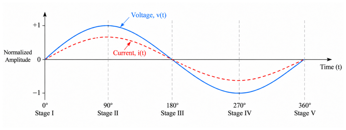
Figure 2.
Proposed electron-mediated transduction and reduction of electromagnetic chains. During increasing excitation, electrons transduce elemental charge photons into organized electric and magnetic chains.
Figure 2.
Proposed electron-mediated transduction and reduction of electromagnetic chains. During increasing excitation, electrons transduce elemental charge photons into organized electric and magnetic chains.
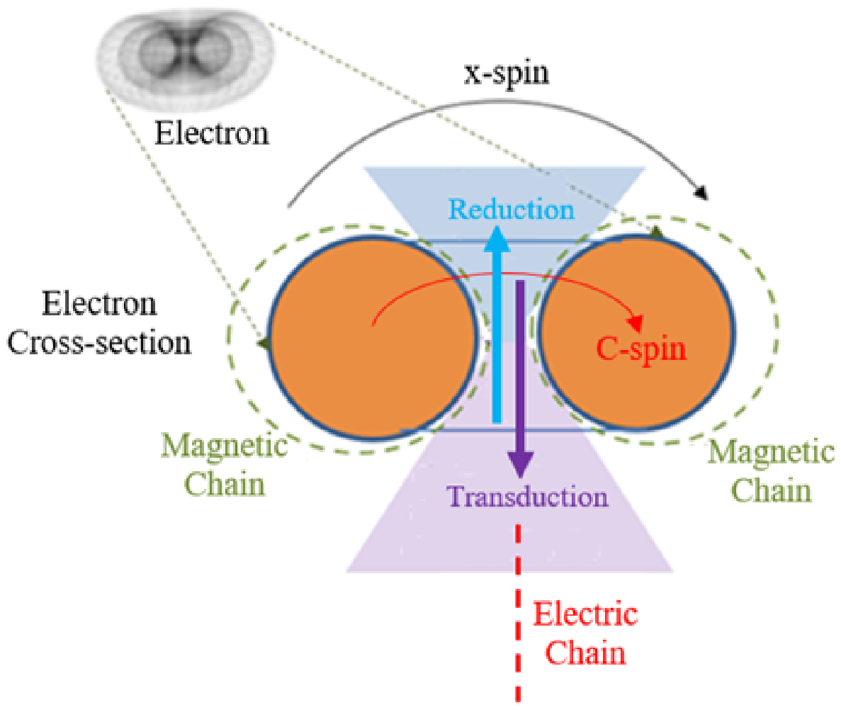
Disclaimer/Publisher’s Note: The statements, opinions and data contained in all publications are solely those of the individual author(s) and contributor(s) and not of MDPI and/or the editor(s). MDPI and/or the editor(s) disclaim responsibility for any injury to people or property resulting from any ideas, methods, instructions or products referred to in the content. |
© 2026 by the authors. Licensee MDPI, Basel, Switzerland. This article is an open access article distributed under the terms and conditions of the Creative Commons Attribution (CC BY) license (http://creativecommons.org/licenses/by/4.0/).
Copyright: This open access article is published under a Creative Commons CC BY 4.0 license, which permit the free download, distribution, and reuse, provided that the author and preprint are cited in any reuse.