

Submitted:
04 September 2026
Posted:
04 September 2026
You are already at the latest version
Abstract
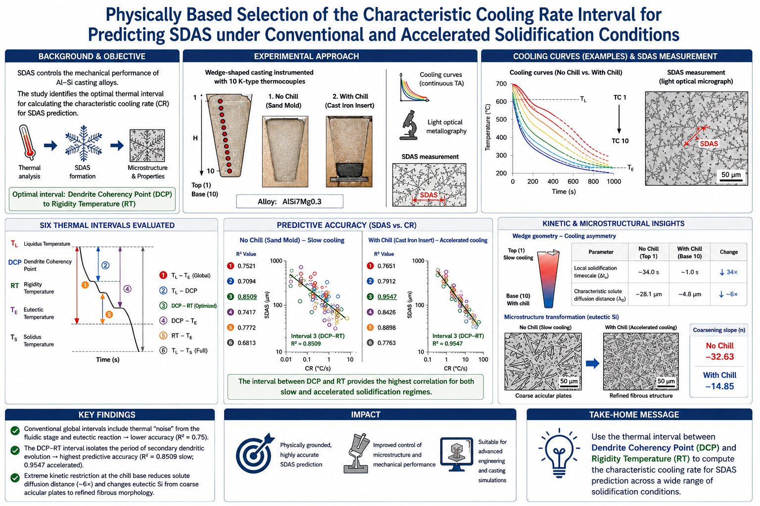
The secondary dendrite arm spacing (SDAS) is a critical microstructural parameter that directly influences the local mechanical performance of AlSi casting alloys. Although the power-law relationship between cooling rate and SDAS is widely acknowledged, the existing literature lacks a standardized framework for selecting the most appropriate solidification thermal interval for calculating this characteristic cooling rate. This study introduces an optimized methodological approach by evaluating solidification kinetics across two distinct thermal regimes: a standard non-isothermal sand mold (no chill) and an accelerated cast iron insert configuration (with chill). Cooling curves of a primary hypoeutectic AlSi7Mg0.3 alloy were continuously recorded via ten calibrated K-type thermocouples along a wedge-shaped casting profile, and the corresponding local SDAS values were quantified using light optical metallography. By mathematically evaluating six distinct thermal analysis boundaries, the results demonstrate that conventional global intervals (e.g., liquidus-to-eutectic) yield lower predictive accuracy (R² ≈ 0.75) due to the accumulation of thermal "noise" from the early fluidic stage and the final eutectic reaction. In contrast, the localized interval bounded strictly between the Dendrite Coherency Point and the Rigidity Temperature (TDCP-TRigidity) achieved excellent correlation for both the baseline slow-cooling regime (R² = 0.8509) and the accelerated regime (R² = 0.9547). This optimized window successfully isolates the exact kinetic timeframe of secondary dendritic evolution and effectively eliminates localized calculation anomalies across the entire spectrum of cooling rates. Thermodynamic analysis reveals a sharp cooling asymmetry in the wedge geometry, where the local solidification timescale collapses by a factor of 34 at the chill base. This extreme kinetic restriction limits the characteristic solute diffusion distance(L≈D.t)) by a factor of nearly six, providing a quantitative physical basis for the significantly flatter coarsening slope (-14.85) under accelerated cooling compared to the baseline regime (-32.63), while simultaneously shifting the eutectic silicon morphology from coarse acicular plates to a highly refined, fibrous structure. The proposed methodology establishes a physically grounded, highly accurate microstructural prediction tool suitable for advanced foundry engineering and casting simulations.
Keywords:
AlSi7Mg0.3 alloy
; thermal analysis (TA)
; dendrite coherency
; rigidity temperature
; secondary dendrite arm spacing (SDAS)
; cooling rate optimization
) achieved excellent correlation for both the baseline slow-cooling regime (R² = 0.8509) and the accelerated regime (R² = 0.9547). This optimized window successfully isolates the exact kinetic timeframe of secondary dendritic evolution and effectively eliminates localized calculation anomalies across the entire spectrum of cooling rates. Thermodynamic analysis reveals a sharp cooling asymmetry in the wedge geometry, where the local solidification timescale collapses by a factor of 34 at the chill base. This extreme kinetic restriction limits the characteristic solute diffusion distance ()) by a factor of nearly six, providing a quantitative physical basis for the significantly flatter coarsening slope (-14.85) under accelerated cooling compared to the baseline regime (-32.63), while simultaneously shifting the eutectic silicon morphology from coarse acicular plates to a highly refined, fibrous structure. The proposed methodology establishes a physically grounded, highly accurate microstructural prediction tool suitable for advanced foundry engineering and casting simulations.
1. Introduction
Al−Si−Mg casting alloys, particularly the hypoeutectic AlSi7Mg0.3 system (equivalent to A356, according to the AA standard from the USA [1,2]), are widely used in high-performance automotive and aerospace applications due to their excellent strength-to-weight ratio, superior castability, and high corrosion resistance [3]. The macroscopic mechanical properties of these components, such as tensile strength, ductility, and fracture toughness, are profoundly dictated by the scale of the local solidified microstructure [4]. Among the various structural parameters, the SDAS is universally recognized as the most critical microstructural feature directly influencing material performance. It is well established that a refined dendritic structure, characterized by a low SDAS value, reduces dislocation motion via grain-boundary-like hardening mechanisms, thereby dramatically improving mechanical properties [5].
The fundamental governing factor controlling the refinement of SDAS is the solidification cooling rate (v). Thermodynamically, this relationship is conventionally modeled using the empirical power law equation [6,7,8]:
where K represents an alloy-dependent material constant, and n is the coarsening exponent, typically around 1/3 for most metallic systems. While this relationship is widespread in computer-aided casting simulations, a critical limitation arises in engineering practice. The existing literature lacks a standardized, physically coherent methodology for calculating the operational cooling rate (v).
Conventionally, researchers compute the cooling rate as a broad average over fixed, global temperature ranges. The most common approach involves taking the average temperature drop across the entire liquidus-solidus solidification interval, defined as dT/dt over the total solidification time, or utilizing a fixed arbitrary range such as 620 °C down to the Al−Si eutectic temperature (). However, these macroscale thermodynamic calculations do not accurately represent the local kinetic window in which the physical growth and coarsening of secondary dendrite arms occur. Calculating cooling rates across boundaries where no secondary arm growth occurs introduces statistical “noise,” reducing the predictive accuracy of the resulting microstructural models.
To bridge this gap, computer-aided cooling-curve TA can be employed to determine the exact rheological transitions in the solidifying mushy zone. Thermodynamically, the initial formation and subsequent structural stabilization of secondary dendrites are constrained by two crucial metallurgical boundaries:
- The Dendrite Coherency Point ( ). This represents the critical thermal point at which primary aluminum (-Aluminum) dendrites grow sufficiently to impinge on one another, forming a continuous, self-supporting solid network [9]. Before , individual dendrites float freely within the melt. Only after the establishment of this coherent network does intensive competitive growth, lateral solute redistribution, and the development of secondary arms truly initiate.
- The Rigidity Temperature (). Occurring immediately after the Al−Si eutectic temperature, represents the point where the solid fraction is sufficiently high to lock the mechanical skeleton into place [10]. At this threshold, mass transport and atomic diffusion within the isolated pockets of remaining liquid metal drop dramatically, stopping any further lateral growth or coarsening (coalescence) of the primary and secondary arms.
Consequently, the localized physical window for the formation and evolution of SDAS is strictly restricted within the specific microstructural window bounded between and . Despite the theoretical soundness of evaluating cooling kinetics inside this localized window, the broader literature continues to rely heavily on macroscale intervals without mathematical or statistical validation of their predictive accuracy. To the best of the authors’ knowledge, no systematic study has yet explicitly quantified and compared how different TA boundaries correlate with the final metallographically measured SDAS values. To address this deficiency, the present study introduces a novel methodological framework evaluated under both conventional and highly accelerated solidification pathways. Utilizing a controlled wedge mold geometry to capture a wide gradient of cooling rates across two distinct experimental regimes a baseline sand mold setup (no chill) and an accelerated configuration featuring a cast iron insert (with chill) this work systematically evaluates and compares six distinct thermal intervals (; ; ; ; ; ) for calculating the characteristic cooling rate of an AlSi7Mg0.3 alloy. By computing the coefficient of determination (R2) for each region across both solidification setups, this research mathematically validates the exact kinetic window that governs secondary dendritic growth, establishing a precise, versatile, and physically rigorous predictive framework for foundry applications
2. Experimental Procedure
Material and Melt Preparation
The commercial primary hypoeutectic AlSi7Mg0.3 alloy was used in this study. The exact chemical composition of the investigated alloy, verified via optical emission spectrometry, is presented in Table 1.
The alloy was melted in an electric resistance furnace. To remove dissolved hydrogen gas and non-metallic inclusions, the melt was degassed for 15 minutes using a rotary degassing unit and inert nitrogen gas. No grain refiners (e.g., AlTi5B1 master alloy) or additional structure modifiers (e.g., AlSr10 master alloy) were introduced into the melt during preparation, ensuring that dendritic growth kinetics were regulated only by the chemical composition and thermal conditions. The pouring temperature immediately before casting was strictly maintained at 740 °C.
Casting Setup and Thermal Analysis
The molten metal was poured by gravity into sand molds prepared using reclaimed sand. To ensure a calm and oxide-free mold filling, a ceramic foam filter was integrated into the gating system. To achieve a wide, controlled gradient in cooling rates, a specific wedge-casting geometry was employed. To evaluate the alloy’s thermal and microstructural response across different solidification regimes, two distinct experimental setups were investigated: a baseline configuration without a chill insert (no chill), and an accelerated configuration utilizing a cast iron chill insert (with chill) positioned at the wedge base.
The only difference between the two experimental configurations was the presence of the cast iron chill insert; all other casting parameters were kept identical. The chill insert (dimensions: 150 × 110 × 30 mm; weighing approximately 3 kg) was manufactured from gray cast iron (EN-GJL-250) and positioned at the bottom section of the wedge mold. The insert was mounted on the inner mold surface to ensure direct contact with the molten alloy immediately after pouring, thereby providing intensive heat extraction over the lower region of the casting. This configuration was deliberately selected to establish an accelerated solidification regime and extend the experimentally accessible range of cooling rates within the same casting geometry.
Solidification paths were recorded using 10 calibrated K-type thermocouples (TCn, n=1,2,…,10) inserted along the vertical centerline of the wedge casting. As illustrated schematically in Figure 1, the sensors were precisely positioned at fixed distances from the narrow base (bottom) of the wedge: 2.0, 4.0, 6.0, 7.5, 10.0, 12.0, 17.0, 19.0, 23.0, and 25.0 cm. Temperature data were collected continuously over time at a high sampling frequency of 5 Hz (5 records per second), ensuring high resolution for subsequent derivative calculations. Under these casting conditions, the average cooling rate for the baseline configuration (no chill) varied from approximately 0.37 °C/s at the fast-cooling bottom to 0.04 °C/s at the slow-cooling top of the wedge. Conversely, the accelerated configuration utilizing the cast iron insert (with chill) achieved substantially elevated cooling kinetics, with average cooling rates ranging from approximately 9.90 °C/s at the chill-contact base to 0.07 °C/s at the top of the mold.
Quantitative Metallography and SDAS Measurement
Following complete solidification and decoring, the wedge casting was sectioned vertically along the centerline plane containing the thermocouple tips. Small metallographic specimens (approximately 10 x 10 mm) were extracted from the immediate vicinity of each thermocouple location to ensure an exact correlation between the local thermal history and the resulting microstructural features. The samples were prepared according to standard metallurgical procedures, involving sequential grinding with SiC papers up to 2500 grit, followed by diamond polishing (down to 1µm) and final etching to reveal the dendritic boundaries. Quantitative characterization of the SDAS was conducted using a light optical microscope. To obtain statistically reliable data, the linear intercept method was utilized at a constant magnification of 25x. For each specimen corresponding to a specific thermocouple position, the final SDAS value (µm) was calculated as the arithmetic average of at least 10 independent linear measurements taken across well-defined, parallel secondary dendrite branches.
3. Results and Discussion
Evaluation of Thermal Analysis Intervals on SDAS Prediction
To systematically determine the most physically coherent and statistically accurate cooling rate parameter for predicting the SDAS, the solidification behavior of the AlSi7Mg0.3 alloy was evaluated under both standard and highly accelerated thermal regimes. Based on the recorded cooling curves within the optimized dendritic growth interval between the Dendrite Coherency Point and the Rigidity Temperature (), the characteristic cooling rates (°C/s) and the corresponding metallographically measured SDAS values (µm) were plotted on a semi-logarithmic scale for both the baseline sand mold configuration (no chill) and the accelerated cast iron insert configuration (with chill), as illustrated in Figure 2.
The empirical relationships for both solidification regimes were mathematically modeled using logarithmic regression equations, and their predictive performance was quantified via the coefficient of determination (R2). To provide a comprehensive and continuous overview of the extracted thermodynamic parameters, localized cooling times, and calculated cooling rates across all ten thermocouple positions, the complete experimental dataset for the baseline non-isothermal setup is structured in Table 3a,b. In contrast, the corresponding high-velocity dataset for the accelerated casting configuration utilizing the chill insert is detailed in Table 4a,b.
Limitations of Conventional Fixed-Temperature Intervals
The models utilizing fixed reference temperatures, such as a constant start temperature of 620 °C or the liquidus temperature (exhibit lower statistical correlations than the optimized growth window. To systematically evaluate these limitations without overcomplicating the graphical presentation, logarithmic regression analysis was performed on all six calculated thermal intervals using the datasets compiled in Table 3b and Table 4b. For the baseline slow solidification regime (no chill), the interval defined from 620 °C to the Al−Si eutectic reaction point () yielded an R² of only 0.7609, while the interval from to yielded an R² of 0.7558. A matching statistical decay was observed in the accelerated regime (with chill), where these broad conventional boundaries consistently failed to exceed an R² threshold of 0.78, indicating a general lack of predictive accuracy across widely varying cooling rates.
From a metallurgical perspective, these conventional approaches introduce significant mathematical “noise” into the derivation of the cooling rate. In the early stages of solidification (immediately below the liquidus line and before the dendrite network impinges), the primary α-Aluminum phase nuclei float freely within the remaining liquid melt. During this fluidic stage, individual dendrites do not influence one another’s growth kinetics, meaning that the structural development and competitive coarsening of secondary dendrite arms have not yet initiated. Consequently, integrating the thermal history of this pre-coherency liquid window artificially increases the solidification time frame, diluting the calculated cooling rate and weakening the model’s predictive capability.
Similarly, boundaries extending down to the final Al−Si eutectic temperature () capture the broad thermal plateau associated with the main eutectic reaction. Since the eutectic phase changes take place at a nearly constant temperature and involve a completely different nucleation mechanism (co-precipitation of aluminum and silicon flakes), this thermal energy does not contribute to the geometry or spacing of the primary aluminum dendrites. The primary dendritic skeleton is established before this phase, so the thermal energy of the eutectic reaction is an analytical artifact in calculating the kinetic cooling rate that governs SDAS.
Quantitative Analysis of Thermodynamic Data Anomalies
The detailed thermodynamic data presented in Table 3a,b highlight why traditional global intervals lead to localized calculation errors, particularly at positions TC2 and TC6.
At position TC2, the cooling rate calculated over the broad liquidus-to-eutectic interval (v3) is 0.2236 °C/s, which is paradoxically lower than its neighbor TC3 (0.1819 °C/s). However, when isolating the true dendritic window (v6, between and . The cooling rate is recorded as 0.2529 °C/s, a more accurate value. This value corresponds exactly to the physical reduction in the measured SDAS (from 61.10 µm at TC3 to 55.40 µm at TC2).
A similar anomaly occurs at position TC6, where the broad interval cooling rate (v1 = 0.0466 °C/s) matches the much slower cooling rate at position TC7 (v1 = 0.0466 °C/s), despite TC6 having a significantly finer SDAS (78.62 µm versus 90.64 µm). By deploying the optimized dendritic growth interval, the calculated cooling rate for TC6 increases to 0.0801 °C/s, while TC7 drops to 0.0446 °C/s.
A prominent calculation discrepancy is also observed under the accelerated solidification regime (Table 4b) at position TC4. Metallographic measurements indicate that position TC4 possesses a highly refined SDAS of 17.60 µm, which is finer than that of position TC3 (23.10 µm) and unexpectedly below that of position TC4 (17.90 µm). However, evaluating the cooling kinetics via the conventional broad liquidus-to-eutectic interval (v3) yields a cooling rate of 2.791 °C/s for TC4, which is lower than the 4.194 °C/s calculated for TC3. This inverse thermodynamic trend fails to justify the physical refinement of the dendrites. In sharp contrast, restricting the analysis to the true dendritic growth window yields an optimized cooling rate (v6) of 4.388 °C/s for position TC4, exceeding the v6 rate for position TC3 (4.017 °C/s). This accurate mathematical correction perfectly aligns with the measured structural refinement.
These localized discrepancies provide clear evidence that broad, nonspecific solidification intervals fail to capture the actual thermal kinetics that drive the local mushy zone. By limiting the thermal calculations strictly to the interval, the model automatically accounts for localized changes in solute redistribution and dendritic impingement, successfully eliminating analytical anomalies.
Validation of the Kinetic Window and Thermal Regime Effects
The integration of accelerated solidification data via the cast iron chill insert expands the predictive capability of the developed model over a comprehensive range of thermal gradients. As illustrated in Figure 2, the characteristic cooling rate (v6), calculated strictly within the localized interval, maintains an exceptionally high statistical reliability under both solidification regimes. The logarithmic regression model for the accelerated setup yielded an outstanding coefficient of determination (R2 = 0.9547), expressed by the trendline equation: y = -14.85 ln(x) + 41.238.
A comparative metallurgical analysis between the two thermal regimes reveals a distinct transition in dendritic growth kinetics. In the lower-cooling-rate spectrum (no chill, v6 < 0.37 °C/s), the solidification kinetics allow sufficient time for extensive solute redistribution and competitive coarsening (coalescence) of secondary arms, resulting in a steep structural response to cooling rate modifications (slope coefficient of -32.63). Conversely, under the highly accelerated thermal regime imposed by the chill insert (with chill, v6 is significantly elevated), the slope coefficient flattens remarkably to -14.85.
This structural stabilization at high solidification rates is governed by the dominance of thermal undercooling over constitutional undercooling. At rapid cooling rates, the local solidification time frame shrinks to mere seconds, mathematically restricting the diffusion distance available for alloying elements. The extreme thermal shock suppresses the competitive ripening mechanism in the arms, forcing the system toward a structural saturation limit, where the final SDAS values stabilize within a highly refined range of 15-25 µm.
This mechanistic interpretation is further supported by the local solidification time available for solute redistribution within the interval. In the baseline (no chill) configuration, this interval extends from approximately 179.1 s at TC1 to more than 1000 s at TC10. In contrast, under the accelerated (with chill) configuration, it is reduced to approximately 5.3 s at TC1 and to just over 500 s at TC10 across the same casting profile.
Using a representative liquid state diffusion coefficient for solute species such as magnesium and silicon in molten aluminum (D ≈ 10⁻⁹–10⁻⁸ m²/s [13]), the characteristic diffusion distance () [14,15]) available for lateral arm coarsening decreases by a factor of nearly six between the two regimes, driven by a 34-fold collapse in the local solidification timeframe at the casting base. This extreme kinetic restriction at position TC1 not only suppresses secondary arm ripening but also fundamentally alters the eutectic silicon morphology, shifting it from coarse acicular plates to a highly refined, fibrous structure. Furthermore, the thermodynamic data reveal a sharp cooling asymmetry along the wedge profile. At the same time, the cast iron insert accelerates solidification by an order of magnitude at the baseline (TC1), its quenching efficiency predictably decays toward the top (TC10), where the local timeframe is only halved from 1139 s to 515.2 s. This substantial reduction in diffusion distance at the chill interface directly impedes the coalescence of adjacent secondary arms, providing a quantitative, physically grounded explanation for the markedly flatter slope coefficient (−14.85) observed under accelerated solidification, compared with the steeper baseline slope (−32.63). The seamless mathematical alignment between the two regimes confirms that isolating the thermal history within the true dendritic mushy zone window provides a robust and universally dependable microstructural prediction tool for foundry engineering.
5. Conclusions
In this study, a novel methodological approach was developed to evaluate the statistical and physical correlations between various solidification cooling-rate intervals (v) and the resulting SDAS in a primary hypoeutectic AlSi7Mg0.3 alloy. Based on computer-aided cooling curve TA and quantitative metallography across a wide thermal gradient, the following main conclusions can be drawn:
Inadequacy of global intervals: Conventional fixed-temperature intervals, such as those calculated from a constant 620 °C threshold or the liquidus temperature down to the eutectic reaction point, yield lower predictive accuracy (R² ≈ 0.75–0.76) during slow solidification. These broad ranges include non-contributing fluidic stages and the final eutectic plateau, which introduce mathematical noise and fail to capture the actual kinetic timescale of secondary dendritic growth.
Superiority of the window: The localized thermal interval bounded by the and the was mathematically validated as a highly accurate and universal predictor for microstructural refinement. It achieved a strong correlation for the baseline slow-cooling regime (R² = 0.8509) and an exceptional correlation for the accelerated solidification regime with the chill insert (R² = 0.9547), proving that isolating the true mushy-zone kinetics works reliably across widely different cooling rates.
Resolution of localized anomalies: Calculating the characteristic cooling rate (v₆) within the window effectively eliminates analytical discrepancies along the casting profile (such as those observed at positions TC2 and TC6). This confirms that isolating the true mushy zone kinetics provides a highly reliable reflection of local microstructural evolution.
Metallurgical significance: The statistical excellence of the optimized model aligns perfectly with the physics of solidification. It isolates the exact window between the physical impingement of the primary dendritic network (), which initiates intensive secondary branching via constitutional undercooling, and the final structural stabilization (), where mass transport is kinetically suppressed.
Diffusion kinetics and structural transformation: The 34-fold collapse in the local solidification timeframe at the chill base restricts the characteristic solute diffusion distance () by a factor of nearly six. This mechanism provides a quantitative, physically grounded explanation for the markedly flatter SDAS coarsening slope under accelerated cooling (-14.85) compared to the baseline regime (-32.63), while simultaneously triggering a fundamental transition in the eutectic silicon morphology from coarse acicular plates to a highly refined, fibrous structure.
The methodology demonstrated in this paper establishes a physically grounded, highly accurate predictive tool. This robust framework is recommended for integration into advanced foundry casting simulations to significantly enhance the accuracy of local microstructural and property predictions in Al-Si components.
Author Contributions
Conceptualization, M.Dj. and S.M.; methodology, M.Dj. and S.M.; software, M.Dj., S.M., and P.N.; validation, M.Dj. and S.M.; formal analysis, M.Dj., S.M., and P.N.; investigation, M.Dj., S.M., and P.N.; resources, M.Dj., S.M., and P.N.; data curation, M.Dj. and S.M.; writing—original draft preparation, M.Dj.; writing—review and editing, S.M.; visualization, M.Dj. and S.M.; supervision, M.Dj. and S.M.; project administration, S.M. All authors have read and agreed to the published version of the manuscript.
Data Availability Statement
The original contributions presented in this study are included in the article/supplementary material. Further inquiries can be directed to the corresponding author.
Acknowledgments
This research has been financially supported by the Ministry of Science, Technological Development, and Innovation of the Republic of Serbia (Contract No: 451-03-33/2026-03/200066).
Conflicts of Interest
Author Srecko Manasijevic was employed by the company, Lola Institute Ltd. The remaining authors declare that the research was conducted without any commercial or financial relationships that could be construed as a potential conflict of interest.
References
- AMS Handbook. Casting, Volume 15; AMS International, USA, 1988; Volume v.1, ISBN 0-87170-007-7.
- Davis, J.R. (Ed.) Aluminum and Aluminum Alloys”; ASM International, USA, 1993. [Google Scholar]
- Kaufman, J.G.; Rooy, E.L. Aluminum alloy castings: Properties, processes, and applications; ASM International, 2004. [Google Scholar]
- Altenpohl, D.G. Aluminum: Technology, Applications, and Environment, 6th ed.; The Aluminum Association Inc. and TMS, 1998. [Google Scholar]
- Robles Hernández, F.C.; Herrera Ramírez, J.M.; Mackay, R. Al-Si Alloys. In Automotive, Aeronautical, and Aerospace Applications; Springer International Publishing AG, 2017. [Google Scholar]
- Spear, R.E.; Gardner, G.R. Dendrite cell size. AFS Trans. 1963, 71, 209−215. [Google Scholar]
- Shabani, M.O.; Mazahery, A. Prediction of Mechanical Properties of Cast A356 Alloy as a Function of Microstructure and Cooling Rate. Arch. Metall. Mater. 2000, 56(3), 671−675. [Google Scholar]
- Easton, M.; Davidson, C.; St John, D. Effect of Alloy Composition on the Dendrite Arm Spacing of Multicomponent Aluminum Alloys. Metall. Mater. Trans. A 2010, 41(6), 1528−1538. [Google Scholar] [CrossRef]
- Chai, G.; Bäckerud, L.; Rolland, T.; Arnberg, L. Dendrite Coherency during Equiaxed Solidification in Binary Aluminum Alloys. Metall. Mater. Trans. 1995, 26A, 965−970. [Google Scholar]
- Huber, G.; Djurdjevic, B.M.; Manasijevic, S. Quantification of feeding regions of hypoeutectic Al-Si (5_7_9 wt.%)-Cu (0–4 wt.%) alloys using cooling curve analysis, In Mass Production Processes; Akdogan, A., Vanli, A.S., Eds.; IntechOpen: London, UK, 2019; p. pp: 1−16. [Google Scholar]
- Djurdjevic, B.M.; Pavlovic, J.; Byczynski, G. The impact of major alloying elements and refiner on the SDAS of Al-Si-Cu alloy. Prakt. Metallogr. 2009, 46(2), 97−114. [Google Scholar] [CrossRef]
- Djurdjevic, B.M.; Huber, G. Determination of Rigidity Point/Temperature using Thermal Analysis Method and Mechanical Technique. J. Alloys Compd. 2014, 590, 500−506. [Google Scholar] [CrossRef]
- Du, Y.; Chang, Y.; Huang, B.; Gong, W.; Jin, Zh.; Xu, H.; Yuan, Z.; Liu, Y.; He, Y.; Xie, F.Y. Diffusion coefficients of some solutes in fcc and liquid Al: Critical evaluation and correlation. Mater. Sci. Eng. 2003, A363, 140–151. [Google Scholar] [CrossRef]
- Flemings, C.M. Solidification Processing . In ISBN 007021283X; McGraw-Hill, 1974. [Google Scholar]
- Kurz, W.; Fisher, D.J. Fundamentals of Solidification, ISBN-100878498044, 3rd ed.; Trans Tech Publications, Switzerland, CRC Press, 1998. [Google Scholar]
Figure 1.
Schematic cross-sectional illustration of the experimental wedge casting geometry, showing the precise centerline locations of the ten K-type thermocouples (TC1 to TC10) and their respective heights from the wedge base.
Figure 1.
Schematic cross-sectional illustration of the experimental wedge casting geometry, showing the precise centerline locations of the ten K-type thermocouples (TC1 to TC10) and their respective heights from the wedge base.

Figure 2.
The SDAS as a function of the optimized characteristic cooling rate (v6) for the AlSi7Mg0.3 alloy under non-isothermal (no chill) and accelerated (with Chill) solidification conditions.
Figure 2.
The SDAS as a function of the optimized characteristic cooling rate (v6) for the AlSi7Mg0.3 alloy under non-isothermal (no chill) and accelerated (with Chill) solidification conditions.


Table 1.
Chemical composition of the investigated AlSi7Mg0.3 alloy (wt.%).
| Element | Si | Fe | Cu | Mn | Mg | Cr | Ni | Zn | Ti |
|---|---|---|---|---|---|---|---|---|---|
| wt.% | 7.01 | 0.11 | 0.07 | 0.068 | 0.348 | 0.001 | 0.003 | 0.012 | 0.0003 |
| Element | Ca | Na | P | Pb | Sb | Sn | Sr | Zr | Al |
| wt.% | 0.0006 | 0.0004 | 0.0006 | 0.002 | 0.003 | 0.0001 | 0.001 | 0.001 | Rest |
Table 2.
a. Characteristic solidification temperatures (°C) and corresponding times (s) recorded across the ten thermocouple positions (TC1 to TC10) under non-isothermal conditions (no chill insert applied).
Table 2.
a. Characteristic solidification temperatures (°C) and corresponding times (s) recorded across the ten thermocouple positions (TC1 to TC10) under non-isothermal conditions (no chill insert applied).
| Position | v1 620 – | v2 620 - | v3 | v4 | v5 | v6 | Measured SDAS | |
|---|---|---|---|---|---|---|---|---|
| °C/s | µm | |||||||
| TC1 | 0.3757 | 0.3026 | 0.3381 | 0.2714 | 0.3239 | 0.2574 | 48.80 | |
| TC2 | 0.2415 | 0.3193 | 0.2186 | 0.2912 | 0.1873 | 0.2529 | 55.40 | |
| TC3 | 0.2017 | 0.1602 | 0.1726 | 0.1370 | 0.1808 | 0.1429 | 61.10 | |
| TC4 | 0.1308 | 0.1543 | 0.1158 | 0.1364 | 0.1152 | 0.1358 | 69.47 | |
| TC5 | 0.0855 | 0.0836 | 0.0784 | 0.0767 | 0.0791 | 0.0774 | 71.49 | |
| TC6 | 0.0466 | 0.0850 | 0.0431 | 0.0791 | 0.0404 | 0.0801 | 78.62 | |
| TC7 | 0.0466 | 0.0492 | 0.0434 | 0.0459 | 0.0421 | 0.0446 | 90.64 | |
| TC8 | 0.0452 | 0.0494 | 0.0418 | 0.0460 | 0.0404 | 0.0446 | 107.96 | |
| TC9 | 0.0451 | 0.0459 | 0.0418 | 0.0427 | 0.0420 | 0.0430 | 114.69 | |
| TC10 | 0.0467 | 0.0453 | 0.0438 | 0.0425 | 0.0444 | 0.0430 | 120.68 | |
Table 3.
b. Calculated cooling rates (°C/s) for the six investigated thermal intervals and the corresponding metallurgically measured SDAS (µm) (without chill insert).
Table 3.
b. Calculated cooling rates (°C/s) for the six investigated thermal intervals and the corresponding metallurgically measured SDAS (µm) (without chill insert).
| P620. | (°C) | (s) | (°C) | (s) | (°C) | (s) | (°C) | (s) | (°C) | (s) |
|---|---|---|---|---|---|---|---|---|---|---|
| TC1 | 620 | 19.8 | 612.7 | 24.6 | 608.0 | 32.7 | 563.2 | 171.0 | 561.9 | 211.8 |
| TC2 | 29.4 | 614.5 | 35.7 | 607.0 | 32.9 | 565.0 | 257.1 | 561.7 | 212.0 | |
| TC3 | 31.8 | 610.4 | 54.0 | 612.0 | 43.5 | 563.3 | 312.9 | 561.5 | 396.9 | |
| TC4 | 34.5 | 612.6 | 46.2 | 612.0 | 44.1 | 562.2 | 476.4 | 564.0 | 397.5 | |
| TC5 | 41.1 | 614.8 | 49.2 | 615.0 | 52.5 | 565.0 | 684.3 | 564.9 | 700.2 | |
| TC6 | 42.0 | 615.7 | 47.1 | 615.9 | 53.0 | 566.0 | 1200.0 | 564.0 | 700.9 | |
| TC7 | 51.3 | 615.9 | 60.0 | 613.0 | 93.6 | 565.8 | 1214.1 | 565.0 | 1169.7 | |
| TC8 | 57.6 | 615.3 | 114.6 | 613.0 | 94.1 | 567.6 | 1217.4 | 565.0 | 1170.8 | |
| TC9 | 73.8 | 614.8 | 106.5 | 614.0 | 132.3 | 567.2 | 1245.4 | 565.0 | 1271.8 | |
| TC10 | 80.7 | 615.6 | 105.0 | 615.0 | 133.0 | 567.5 | 1203.9 | 566.0 | 1272.0 |
Table 4.
a. Characteristic solidification temperatures (°C) and corresponding times (s) recorded across the ten thermocouple positions (TC1 to TC10) under non-isothermal conditions (with chill insert applied).
Table 4.
a. Characteristic solidification temperatures (°C) and corresponding times (s) recorded across the ten thermocouple positions (TC1 to TC10) under non-isothermal conditions (with chill insert applied).
| Position | (°C) | (s) | (°C) | (s) | (°C) | (s) | (°C) | (s) | (°C) | (s) |
|---|---|---|---|---|---|---|---|---|---|---|
| TC1 | 620 | 1.2 | 610.8 | 1.9 | 597.8 | 6.9 | 551 | 12.1 | 557 | 12.2 |
| TC2 | 5.1 | 610.7 | 5.7 | 598 | 7.1 | 553.3 | 12.6 | 557 | 12.5 | |
| TC3 | 5.7 | 614.3 | 6.7 | 601.8 | 11.4 | 558.1 | 20.1 | 556 | 22.8 | |
| TC4 | 6.6 | 616.1 | 6.9 | 601.2 | 11.6 | 560 | 27 | 556 | 21.9 | |
| TC5 | 7.4 | 615.9 | 7.8 | 600.1 | 17 | 562.4 | 42.6 | 555.6 | 55.2 | |
| TC6 | 7.5 | 615.5 | 8.1 | 600 | 17.1 | 564 | 49.8 | 555.1 | 55.4 | |
| TC7 | 12.9 | 615.8 | 21.6 | 601.5 | 78 | 563.5 | 259.9 | 561.1 | 280 | |
| TC8 | 21 | 615.6 | 40.2 | 601.8 | 78.2 | 563.6 | 259 | 561.7 | 278 | |
| TC9 | 47.1 | 616.3 | 67.5 | 602 | 254.7 | 563.7 | 742.2 | 563.3 | 771.5 | |
| TC10 | 51.3 | 616.2 | 69 | 601.7 | 255 | 564.3 | 750 | 563 | 770.2 |
Table 5.
b. Calculated cooling rates (°C/s) for the six investigated thermal intervals and the corresponding metallurgically measured SDAS (µm) (with chill insert).
Table 5.
b. Calculated cooling rates (°C/s) for the six investigated thermal intervals and the corresponding metallurgically measured SDAS (µm) (with chill insert).
| Position | v1 620 – | v2 620 - | v3 | v4 | v5 | v6 | Measured SDAS | |
|---|---|---|---|---|---|---|---|---|
| °C/s | µm | |||||||
| TC1 | 6.330 | 5.727 | 9.9 | 5.223 | 9.75 | 7.698 | 14.3 | |
| TC2 | 8.893 | 8.513 | 8.318 | 7.897 | 8.127 | 7.592 | 17.9 | |
| TC3 | 4.298 | 3.742 | 4.194 | 3.621 | 5.022 | 4.017 | 23.1 | |
| TC4 | 2.941 | 4.183 | 2.791 | 4.006 | 2.675 | 4.388 | 17.6 | |
| TC5 | 1.636 | 1.347 | 1.537 | 1.272 | 1.472 | 1.164 | 30.5 | |
| TC6 | 1.323 | 1.354 | 1.235 | 1.276 | 1.101 | 1.172 | 30.1 | |
| TC7 | 0.228 | 0.220 | 0.219 | 0.211 | 0.208 | 0.2 | 58.8 | |
| TC8 | 0.236 | 0.226 | 0.237 | 0.226 | 0.211 | 0.201 | 68.8 | |
| TC9 | 0.080 | 0.078 | 0.077 | 0.075 | 0.078 | 0.074 | 81.5 | |
| TC10 | 0.079 | 0.079 | 0.076 | 0.075 | 0.075 | 0.075 | 86.8 | |
Disclaimer/Publisher’s Note: The statements, opinions and data contained in all publications are solely those of the individual author(s) and contributor(s) and not of MDPI and/or the editor(s). MDPI and/or the editor(s) disclaim responsibility for any injury to people or property resulting from any ideas, methods, instructions or products referred to in the content. |
© 2026 by the authors. Licensee MDPI, Basel, Switzerland. This article is an open access article distributed under the terms and conditions of the Creative Commons Attribution (CC BY) license (http://creativecommons.org/licenses/by/4.0/).
Copyright: This open access article is published under a Creative Commons CC BY 4.0 license, which permit the free download, distribution, and reuse, provided that the author and preprint are cited in any reuse.