

Submitted:
30 August 2026
Posted:
31 August 2026
You are already at the latest version
Abstract
This note documents, at a preliminary stage, a propeller concept for small expendable interceptor UAVs cruising near 300 km/h (83 m/s). The concept derives from the DA4052 (9 × 6.75 in variant), an open-geometry small-scale propeller designed at the University of Illinois at Urbana-Champaign and characterised by wind-tunnel measurement in the UIUC Propeller Database. Four geometric modifications are proposed and have been implemented in CAD and realised as a three-blade fused-filament (PLA) article: truncation of both tip and root, giving a modified rotor diameter of 170 mm; an enlarged root chord in place of the parent’s root dip; replacement of the 12 % PROFOIL sections by the 14.6 % thick MH 113 propeller section; and a large increase in blade twist, raising pitch-to-diameter ratio from 0.75 to 2.23. A minimal cylindrical shroud, without lip contouring, diffuser or nozzle, is proposed as a subsequent noise-mitigation step. A single static bench run produced 6 N of thrust at an unrecorded rotational speed. The purpose of this note is to place the concept and its hypotheses on the public record. Computational, structural and experimental characterisation are ongoing. No validated performance claim is made here.
Keywords:
propeller design
; high advance ratio
; interceptor UAV
; additive manufacturing
; blade element momentum theory
; DA4052
; MH 113
; ducted propeller
; propeller noise
1. Motivation
Small-scale propeller research is concentrated at low advance ratio. Published databases, including the campaign from which the parent blade is drawn, characterise rotors at operating points typical of hover, climb and modest forward flight. Interceptor-class UAVs impose a different requirement. Fielded systems of the Sting class, developed by Wild Hornets against Shahed-type loitering munitions, are specified by their manufacturer at a maximum speed of 280 km/h, and test footage released in 2025 showed 315 km/h [5]; the targets they pursue cruise at 200–250 km/h. An interceptor must overtake what it chases, so its propulsor has to sustain axial flight an order of magnitude faster than multirotor cruise, for missions of a few minutes, on airframes that are expendable by design. A propeller optimised for low advance ratio then operates far from its design point, with the outboard sections approaching or entering negative incidence.
The expendable premise adds a manufacturing constraint. Injection moulding and carbon-fibre layup suit volume production but not rapid, distributed, low-volume manufacture. Additive manufacture suits that role, provided the blade is shaped for it. This note addresses both constraints on a parent blade whose geometry and measured performance are public.
2. Parent Propeller
The parent geometry is the DA4052 in its 9 × 6.75 in variant (229 mm diameter, p/D = 0.75), designed at UIUC using the PROFOIL inverse method with three 12 % thick sections along the blade [1,2,3]. It is adopted only as a starting point and as a future validation case: its geometry is published in tabulated form, its performance is independently measured, a three-blade configuration matching the modified rotor is reported, and it was itself 3D printed for the original campaign. Full parent data are not reproduced here; the subject of this note is the modified rotor.
3. Proposed Modification
Four geometric modifications are applied to the parent, together with a proposed shroud. They are coupled: the truncation is what permits the enlarged root chord, the thicker section and the higher twist to be carried without an unacceptable structural or inertial penalty.
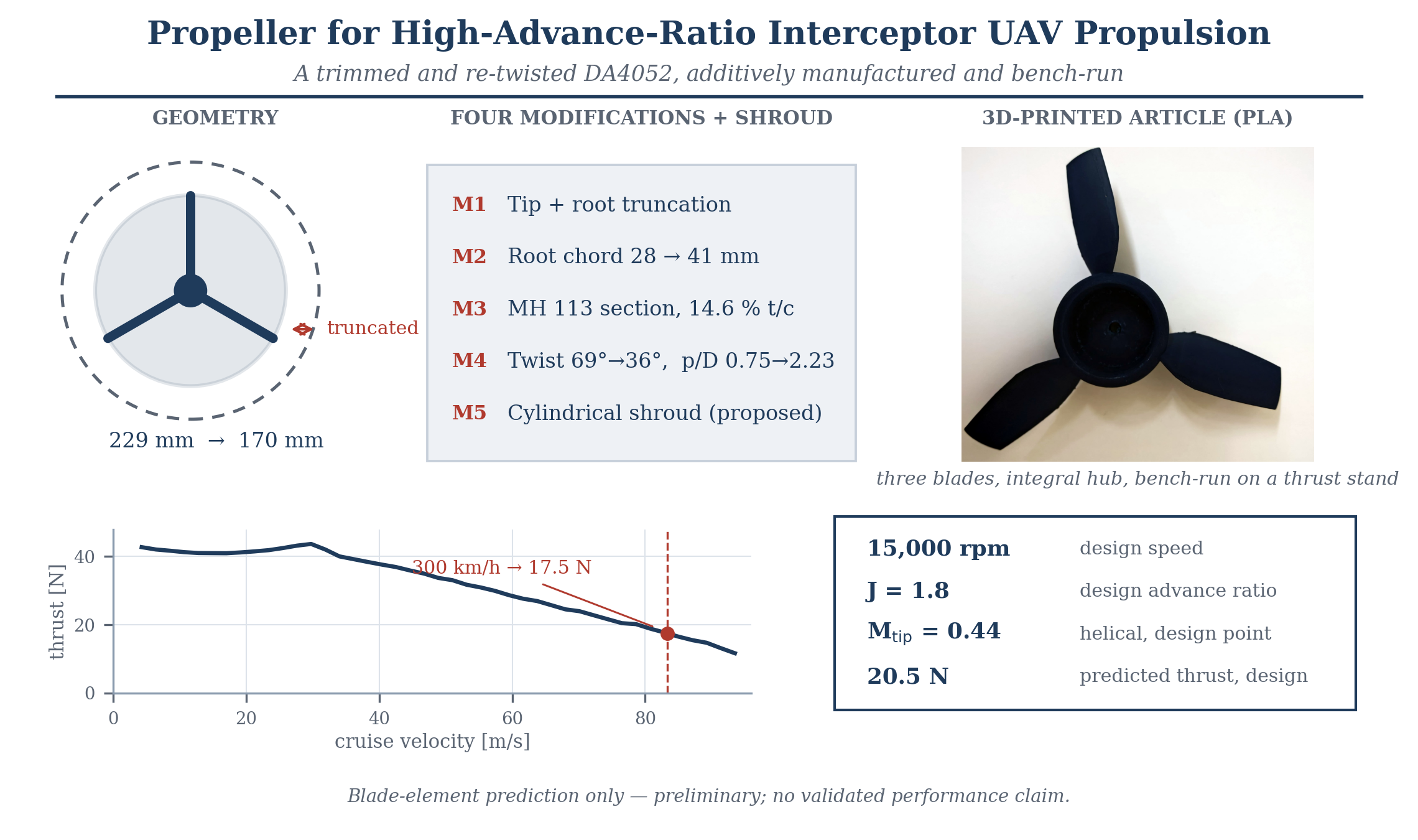
M1 — Truncation. The blade is truncated at both ends. The tip trim removes the parent’s knife-edge outboard region, whose local thickness falls below 1 mm at this scale and which is the first part to fail in a printed blade; the root trim removes the narrow-chord dip. The 229 mm parent becomes a 170 mm rotor: a 60 mm blade on a 25 mm hub radius. Disc area, and therefore static thrust, is reduced, accepted as a deliberate trade in a design sized for high-speed axial flight rather than hover.
M2 — Root-chord override. The chord at the new root station is raised to 28 mm and ramped smoothly to the parent’s natural 41 mm peak, in place of the parent’s root dip. This places material where the bending moment is greatest rather than where the parent’s low-Reynolds optimisation had thinned it.
M3 — Section replacement. The 12 % PROFOIL sections are replaced throughout by the MH 113, a 14.6 % thick, 6.4 % cambered section from Hepperle’s MH 112–117 family of ultralight-aircraft propeller sections [4]. The family is graded in thickness for spanwise use, so a thinner member outboard remains open.
M4 — Twist increase. Twist follows constant ideal-pitch geometry, β = α + arctan(V/ωr), with α = 6° at the design condition, giving 69° at the root station and 36° at the tip (Figure 1). Geometric pitch at 75 % R is about 380 mm, so p/D = 2.23 against the parent’s 0.75. This modification defines the concept; M1–M3 make it realisable in a printed blade.
M5 — Cylindrical shroud (proposed). A plain ring around the rotor, with no lip contouring, diffuser or nozzle, is proposed for noise mitigation. It is deliberately the simplest possible shroud, so any acoustic benefit is attributable to the shroud rather than to a redesigned flow path.
The rotor has three blades and a solidity of about 0.24. It is analysed at 15,000 rpm, so that nD = 42.5 m/s. The design point is J = 1.8, that is 76.5 m/s or 275 km/h; the 300 km/h target corresponds to J = 1.96 and therefore sits slightly beyond it. Rotational tip speed is 133.5 m/s, and the helical tip Mach number is 0.44 at the design point.

Table 1.
Summary of the modifications applied to the parent geometry.
| Mod. | Change | Primary intent |
| M1 | Tip + root truncation (229 → 170 mm) | Remove fragile tip; margin |
| M2 | Root chord 28 mm, ramped to 41 mm | Material at max bending |
| M3 | MH 113 section (14.6% t/c) | Printability, strength |
| M4 | Twist 69°→36°; p/D 0.75 → 2.23 | Design point at high J |
| M5 | Cylindrical shroud | Noise (proposed) |
4. Design Hypotheses
The following are the claims to be tested, not results.
H1. The modified blade attains higher peak propulsive efficiency than the parent at advance ratios corresponding to 83 m/s axial flight, at the cost of reduced static and low-J thrust.
H2. Reduced span combined with increased section thickness yields a positive structural margin at maximum operating rotational speed for an additively manufactured polymer blade over a mission of a few minutes.
H3. Under load the printed blade untwists: centrifugal and aerodynamic forces bend it towards a flatter pitch, so the blade that flies is not the blade that was drawn. The hypothesis is that this pitch loss is large enough that predictions made on the rigid CAD geometry must be corrected before they can fairly be compared with measurement.
H4. A plain cylindrical shroud reduces radiated tonal noise but produces a net propulsive-force penalty at the high-advance-ratio design point once shroud drag is accounted for.
H1 and H4 are addressed by computation and, ultimately, experiment; H2 and H3 by finite-element analysis with imported aerodynamic loading. H4 is stated in the form expected to hold; a neutral or beneficial net-force result would itself be reportable.
5. Preliminary Assessment
The modified rotor has been analysed in QBlade using blade-element-momentum theory at 15,000 rpm over advance ratios from 0.1 to 2.2. The predicted thrust is shown in Figure 2. It is nearly flat at about 41–44 N below 30 m/s, peaks at 43.7 N at 29.8 m/s, and then falls steadily. At the J = 1.8 design point the predicted thrust is 20.5 N and at 300 km/h it is 17.5 N; linear extrapolation of the computed trend places zero thrust near 116 m/s.
These are indicative figures only. Blade-element methods are least reliable in exactly the regime that defines this concept: high twist, low aspect ratio after trimming, and strong three-dimensional tip flow. The corresponding parent computation and the overlay against the published wind-tunnel data, which are what would establish the fidelity of the method on a known case, are not yet included; no measured performance is claimed.
6. Manufactured Article
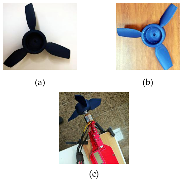
The modified rotor has been manufactured as a single three-blade part by fused filament fabrication in PLA (Figure 3), with an integral deep-skirted hub. Print orientation, layer height, wall count and infill govern the anisotropy of the part and are reported as part of the specimen definition. The trim leaves a squared, unfaired tip, and the deposited build layers are visible on both faces in Figure 3; tip treatment is not part of the present concept and its aerodynamic and acoustic effect is left to the computational study. PLA is a prototyping material here, for geometry verification and low-speed bench work; the flight material remains open pending structural analysis. An ogival spinner of about 50 mm diameter is intended to fair the hub region and is not part of the article shown.
The rotor has been installed on a thrust stand and run on the bench (Figure 3c). The article is dimensionally sound, balances on the shaft and turns without contact, and a single static run produced 6 N of thrust. Rotational speed was not instrumented, and the throttle was not advanced further because rotor noise became the limiting factor at the test location. The measurement therefore establishes that the article runs and produces thrust, but it cannot be placed on the predicted curve of Figure 2, which requires a known rotational speed; no torque or acoustic measurement was taken. A controlled campaign with a tachometer, containment shielding and a stated uncertainty budget is required before any measured quantity is compared with prediction.
7. Limitations
No validated aerodynamic performance is claimed; the blade-element results are preliminary.
The modified geometry operates outside the advance-ratio range over which the parent was measured, so the reference data validate the method, not the operating point.
No structural analysis is reported; hypothesis H2 is stated but untested.
The single static measurement of 6 N was taken without a rotational-speed reading, so it cannot be compared with the prediction of Figure 2.
The shroud (M5) is a proposal; no aerodynamic or acoustic evaluation is presented.
Aeroelastic deformation is unquantified; predictions assume rigid geometry.
The blade-element results use incompressible section data; at a helical tip Mach number of 0.44 a 14.6 % thick, 6.4 % cambered section warrants a compressible check near the tip.
8. Ongoing Work
In progress for a subsequent full-length publication: RANS computation of the parent against the published data as a validation case, then a full advance-ratio sweep of the modified blade; one-way fluid-structure analysis across candidate print materials, including the deformed blade shape; a controlled static thrust campaign on the stand of Figure 3c; and evaluation of the shroud in net propulsive force and tonal noise.
9. Statement of Originality and Priority
The design concept described here — the truncation, root-chord override, section replacement, twist law and proposed cylindrical shroud applied to the DA4052 9 × 6.75 in parent geometry for high-advance-ratio interceptor propulsion — was conceived and developed by the author, who also produced the CAD definition, the manufactured article and the preliminary analysis reported here. This note is published to establish the date of the concept and its attribution. The DA4052 geometry and its wind-tunnel data are the work of the cited authors and are used as an open reference.
Declaration of Generative AI Use
The author used a generative AI assistant (Claude, Anthropic) to draft and edit the text of this note and to check derived quantities. Figure 1 and Figure 2 were plotted by the assistant from QBlade output exported by the author; Figure 3 comprises the author’s own photographs. The design concept, CAD geometry, blade definition, manufactured article, QBlade simulations and bench measurement are entirely the author’s own work. The author reviewed all content and takes full responsibility for it.
References
- Deters, R. W.; Ananda, G. K.; Selig, M. S. Reynolds Number Effects on the Performance of Small-Scale Propellers; AIAA Paper 2014-2151: Atlanta, GA, June 2014. [Google Scholar]
- Brandt, J. B.; Deters, R. W.; Ananda, G. K.; Dantsker, O. D.; Selig, M. S. UIUC Propeller Database, Vols. 1–4. In contains the DA4052 data; University of Illinois at Urbana-Champaign; Vol. 2.
- Deters, R. W. Performance and Slipstream Characteristics of Small-Scale Propellers at Low Reynolds Numbers. Ph.D. Dissertation, University of Illinois at Urbana-Champaign, 2014. [Google Scholar]
- Hepperle, M. MH 113 coordinates, UIUC Airfoil Coordinates Database. [PubMed]
- Wild Hornets, STING interceptor. 2026. Available online: wildhornets.com/en/sting-interceptor.
Figure 1.
Blade definition of the modified rotor: twist and normalised chord against radial station, with R = 85 mm. The blade runs from r/R = 0.29 at the hub to the tip; chord peaks at c/R = 0.48 near mid-span and twist falls monotonically from 69° to 36°.
Figure 1.
Blade definition of the modified rotor: twist and normalised chord against radial station, with R = 85 mm. The blade runs from r/R = 0.29 at the hub to the tip; chord peaks at c/R = 0.48 near mid-span and twist falls monotonically from 69° to 36°.
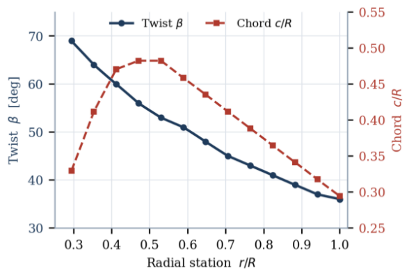
Figure 2.
Predicted thrust of the modified rotor against cruise velocity, blade-element-momentum solution at 15,000 rpm (170 mm diameter, nD = 42.5 m/s), with the J = 1.8 design point and the 300 km/h target marked. The parent-blade curves and the published wind-tunnel overlay are to be added.
Figure 2.
Predicted thrust of the modified rotor against cruise velocity, blade-element-momentum solution at 15,000 rpm (170 mm diameter, nD = 42.5 m/s), with the J = 1.8 design point and the 300 km/h target marked. The parent-blade curves and the published wind-tunnel overlay are to be added.
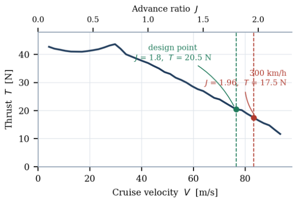
Figure 3.
The manufactured article. (a) and (b) opposite faces of the three-blade rotor, showing the squared tips left by the span trim and the deposited build layers. (c) The rotor installed on the thrust stand for preliminary bench running, driven by a brushless outrunner through a 100 A electronic speed controller with current monitored by clamp meter. Captions to state printer, material, nozzle diameter, layer height, wall count, infill density and print orientation, together with stand, motor and controller designations; a scale reference should be added.
Figure 3.
The manufactured article. (a) and (b) opposite faces of the three-blade rotor, showing the squared tips left by the span trim and the deposited build layers. (c) The rotor installed on the thrust stand for preliminary bench running, driven by a brushless outrunner through a 100 A electronic speed controller with current monitored by clamp meter. Captions to state printer, material, nozzle diameter, layer height, wall count, infill density and print orientation, together with stand, motor and controller designations; a scale reference should be added.
Disclaimer/Publisher’s Note: The statements, opinions and data contained in all publications are solely those of the individual author(s) and contributor(s) and not of MDPI and/or the editor(s). MDPI and/or the editor(s) disclaim responsibility for any injury to people or property resulting from any ideas, methods, instructions or products referred to in the content. |
© 2026 by the authors. Licensee MDPI, Basel, Switzerland. This article is an open access article distributed under the terms and conditions of the Creative Commons Attribution (CC BY) license (http://creativecommons.org/licenses/by/4.0/).
Copyright: This open access article is published under a Creative Commons CC BY 4.0 license, which permit the free download, distribution, and reuse, provided that the author and preprint are cited in any reuse.