
Submitted:
18 August 2026
Posted:
20 August 2026
You are already at the latest version
Abstract
In deep-water environments, the coupled effects of hydrostatic pressure, explosion-induced shock waves, and bubble pulsation can produce complex nonlinear dynamic responses and instability in stiffened cylindrical shells. Clarifying these response mechanisms is critical for the safety assessment and blast-resistant design of deep-sea equipment. In this study, an acoustic-structure coupled numerical method was developed for stiffened cylindrical shells subjected to underwater explosion loading and validated using deep-water explosion tests conducted in a pressure vessel. The results show that the proposed method predicts the dynamic response of stiffened cylindrical shells under deep-water explosion loading with satisfactory accuracy. Based on this validated model, a systematic investigation was conducted to evaluate the effects of hydrostatic pressure, stand-off distance, shell-plate thickness, and stiffener number on the deep-water explosion response of stiffened cylindrical shells. The findings provide practical guidance for blast-resistant design and parameter optimization of deep-water stiffened cylindrical shells.
Keywords:
deep-water explosion
; stiffened cylindrical shells
; fluid-structure interactions
1. Introduction
Stiffened cylindrical shells are typical pressure-bearing components in deep-sea equipment and are widely used in submarines, unmanned underwater vehicles, deep-sea pressure vessels, and other underwater systems. As the operating depth and service environments of deep-sea equipment continue to expand, these structures must withstand not only sustained hydrostatic pressure but also potential underwater explosion loading. Underwater explosion loading generally consists of a high-peak, short-duration shock wave and a longer-duration bubble-pulsation load with a broader action range [1,2,3]. In deep-water environments, hydrostatic pressure further modifies the bubble-pulsation process, the initial stress state of the structure, and the subsequent deformation evolution [4]. For stiffened cylindrical shells, stiffeners also alter the spanwise stiffness of shell plates, local constraint conditions, and the distribution of plastic damage. Therefore, the dynamic response of stiffened cylindrical shells subjected to deep-water explosion loading cannot be regarded simply as local deformation induced by a single shock wave. Rather, it is a complex response governed by the coupled effects of hydrostatic pressure, shock waves, bubble pulsation, and stiffener constraints. Investigating the dynamic response characteristics and parametric influence mechanisms of these structures is therefore essential for structural safety assessment, blast-resistant design, and stiffener-parameter optimization of deep-sea equipment.
In theoretical research, existing studies have mainly focused on the evaluation of underwater explosion loading, simplified fluid-structure coupling, and response prediction for cylindrical shells. Early investigations commonly represented complex explosive loading using equivalent parameters, such as peak pressure, impulse, and shock factor, thereby establishing relationships between explosion intensity and structural response. On this basis, Yao et al. [5] further refined the shock-factor characterization method from the perspective of structural energy input, enabling a more accurate representation of differences in structural deformation responses under underwater explosion loading. For transient coupling between the water domain and the structure, the doubly asymptotic approximation proposed by Geers [6] provides a classical simplified framework for underwater explosion fluid-structure interaction analysis, in which the complex radiation effects of the water medium are incorporated into structural response calculations through equivalent boundary conditions.
Regarding response prediction for cylindrical-shell structures, Pédron and Combescure [7] used modal analysis and perturbation methods to analyze the transient response of stiffened cylindrical shells, whereas Brochard et al. [8] introduced the equivalent added mass of the surrounding fluid into a simplified shell model to estimate the deformation response of cylindrical shells subjected to underwater shock waves. With increasing attention to deep-water explosion problems, Brochard et al. [9,10] further incorporated hydrostatic-pressure corrections into the original simplified model to predict the response of deeply submerged cylindrical shells under underwater explosion loading. In recent years, semi-analytical methods and engineering estimation models have also been applied to rapidly predict the dynamic response of cylindrical shells subjected to far-field underwater explosions and deep-water explosions [11,12]. These theoretical approaches provide an important basis for the equivalent characterization of underwater explosion loading, the simplification of fluid-structure coupling, and the prediction of the global response of cylindrical shells.
In numerical simulation, finite element methods and fluid-structure coupling algorithms have provided powerful tools for investigating the structural response of cylindrical shells subjected to underwater explosions. Existing studies initially focused on the transient response, local plastic deformation, and dynamic buckling modes of unstiffened or simplified cylindrical shells, thereby establishing a foundation for understanding the fundamental response mechanisms of cylindrical shells under underwater explosion loading [13,14,15,16]. As the complexity of the research objects has increased, the blast-resistant response of stiffened cylindrical shells and complex shell structures has received extensive attention. Praba and Ramajeyathilagam [17] analyzed the large-deformation behavior of ring-stiffened cylindrical shells subjected to underwater explosions, whereas Zhu et al. [18] conducted early experimental and numerical investigations of the underwater explosion response of ring-stiffened cylindrical shells. Subsequent studies further extended to stiffened double cylindrical shells, protective configurations, contact explosions on double-shell structures, inter-stiffener plate deformation in stiffened conical-cylindrical shells, and the coupled action of bubbles generated by double charges. These studies revealed the effects of stiffening configuration, shell-plate span, material form, and explosion parameters on local deformation, damage distribution, and blast resistance [19,20,21,22,23]. In recent years, Gao et al. [24,25] further investigated the damage modes of ring-stiffened cylindrical shells and titanium-alloy stiffened cylindrical shells, establishing correlations between explosion parameters and failure modes. These studies demonstrate that stiffened configurations can significantly alter the local stiffness distribution and damage evolution path of cylindrical shells.
However, most related investigations have been conducted under shallow-water or ambient-pressure underwater explosion conditions, with insufficient consideration of the effects of the initial stress state and subsequent deformation development under deep-water hydrostatic pressure. For deep-water explosion environments, Qu et al. [26] examined the effects of water depth and charge weight on the dynamic buckling modes of cylindrical shells, showing that the buckling responses induced by shock waves and bubble pulsation differ substantially. Wang et al. [27] combined deep-water explosion tests with numerical simulations and revealed the staged response and dynamic buckling modes of cylindrical shells under the combined effects of hydrostatic pressure, shock waves, and bubble pulsation. Related studies have also addressed response estimation for cylindrical shells subjected to deep-water explosions, damage caused by far-field lateral explosions, near-field explosion responses, and the dynamic behavior of cylindrical shells under the coupled effects of shock waves, bubble pulsation, and hydrostatic pressure [4,12,28,29].
In experimental research, underwater explosion tests provide direct evidence for identifying the dynamic response of shell structures and validating numerical models. Existing experiments initially focused on the dynamic response and shock-induced damage of cylindrical shells under ambient-pressure or shallow-water conditions. Through small-scale underwater explosion tests, these studies obtained strain, acceleration, deformation, and damage responses of cylindrical shells, thereby providing a basis for the subsequent calibration of numerical models [30,31]. As the investigated structures have become increasingly complex, experimental studies have further expanded to cylinder-water-cylinder systems, double cylindrical shells, semi-cylindrical shells, and stiffened cylindrical shells, with particular attention given to the effects of charge configuration, structural form, stand-off distance, and scaling relationships on local deformation and damage modes [21,25,32,33]. These studies have deepened the understanding of underwater explosion damage characteristics in stiffened cylindrical shell structures.
Nevertheless, most were conducted under shallow-water or ambient-pressure conditions and therefore cannot adequately capture the influence of deep-water hydrostatic pressure on the initial structural stress state and subsequent deformation evolution. In the context of hydrostatic pressure or deep-water environments, Gupta et al. [34] and DeNardo et al. [35] used pressure devices to investigate the dynamic instability of cylindrical and double-shell composite cylindrical structures under combined static pressure and shock loading. Bodurtha et al. [36] further examined the dynamic instability of internally stiffened hollow cylinders in a confined underwater environment. Earlier, Nagai [37] conducted damage tests on cylindrical shells subjected to underwater explosions and summarized their typical damage morphologies and failure modes. Wang et al. [27] combined deep-water explosion tests with numerical simulations to analyze the response process and buckling modes of cylindrical shells at different water depths. In addition, experimental studies on composite cylindrical shells, anisotropic cylindrical shells, and the dynamic response of cylindrical shells subjected to near-field or contact explosions have provided supplementary evidence for analyzing structural instability and damage under hydrostatic-pressure or shock-loading conditions [38,39,40].
In summary, existing studies have advanced the understanding of cylindrical-shell responses to underwater explosions from theoretical, numerical, and experimental perspectives. However, most related work remains focused either on explosion-induced damage in stiffened cylindrical shells under shallow-water or ambient-pressure conditions, or on the deformation and buckling responses of unstiffened or simplified cylindrical shells in deep-water environments. In comparison, the dynamic response of stiffened cylindrical shells subjected to deep-water explosion loading is substantially more complex. Systematic investigations into the evolution of flow-field pressure, structural stress distribution, plastic damage, and deformation response remain insufficient, and the influence mechanisms of parameters such as water depth, stand-off distance, shell-plate thickness, and stiffener arrangement require further clarification.
Therefore, this study focuses on stiffened cylindrical shells subjected to deep-water explosion loading and investigates their dynamic response characteristics and parametric influence mechanisms through a combination of deep-water explosion pressure-vessel tests and numerical simulations. The reliability of the numerical model is validated using free-field pressure, wall pressure on the cylindrical-shell surface, and strain data obtained at representative locations. On this basis, the evolution of flow-field pressure, stress distribution, plastic damage, and deformation response under a representative working condition is analyzed. The effects of water depth, stand-off distance, shell-plate thickness, and stiffener arrangement on the dynamic response of stiffened cylindrical shells are then further discussed. Section 2 presents the numerical methods and models, together with their corresponding validation. Section 3 discusses the effects of key factors on the dynamic response of cylindrical shell structures subjected to deep-water explosion loading. Finally, the main conclusions are presented in Section 4.
2. Numerical Methods and Validation for Stiffened Cylindrical Shells Subjected to Deep-Water Explosions
2.1. Numerical Method for Analyzing the Response of Stiffened Cylindrical Shells Subjected to Deep-Water Explosions
In this study, all stand-off distances are greater than 2.5 times the maximum bubble radius generated by the underwater explosion. Accordingly, the fluid is modeled as an acoustic medium, and an acoustic-structural coupling approach in Abaqus/Explicit is used to establish a response model for stiffened cylindrical shells subjected to deep-water explosions.
The acoustic-structural coupling formulation implemented in Abaqus/Explicit has been extensively described in the literature, including the Abaqus Analysis User's Guide [41] and the work of Geers and Hunter [3]. Therefore, only the fundamental theoretical principles and key modeling settings are briefly summarized here. The governing equation of the structure [42] is expressed as follows:
where is the mass matrix, is the damping matrix, is the stiffness matrix, is the displacement vector, is the velocity vector, is the acceleration vector, and is the external force vector acting on the structure, which can be expressed as:
where denotes the incident-wave pressure, denotes the scattered-wave pressure, is the initial pressure, [T] is the transformation matrix relating the nodal surface forces of the structure to those of the fluid, and is the diagonal area matrix associated with an element in the fluid mesh.
The acoustic and structural surfaces at the interface are coupled, while the outer surface of the fluid domain is assigned a non-reflecting boundary condition. A total-wave formulation is employed to simulate shock-wave propagation and its coupled interaction with the structure. In addition, a cavitation pressure cut-off is introduced to represent the pressure truncation phenomenon that occurs during deep-water explosions.
The incident-wave pressure is evaluated by accounting for the physical characteristics of deep-water loading. Because conventional empirical formulations are not universally applicable across different water depths, this study adopts the one-dimensional, spherically symmetric, free-field underwater explosion model developed by Jin et al. [43]. In this approach, the spherically symmetric compressible Euler equations are solved using the Runge-Kutta Discontinuous Galerkin (RKDG) method to determine the deep-water explosion loading. The conservative form of these one-dimensional Euler equations is expressed as follows:
where the vector of conservative variables U, the flux vector f(U) and the geometric source term S(U) can be expressed as follows:
where t denotes time, x denotes the spatial coordinate, ρ is the fluid density, v is the velocity, p is the fluid pressure, and E is the total energy per unit volume. The total energy E is defined as follows:
where e denotes the internal energy per unit mass of the fluid, defined as a function of the fluid pressure p and density ρ, satisfying the following relation:
The detonation products and surrounding water medium are described using the Jones-Wilkins-Lee (JWL) equation of state and the Tait equation of state, respectively. The JWL equation of state defines the relationship among pressure, density, and internal energy in the detonation gases. During underwater detonation, the pressure p can be expressed as follows:
where A, B, R1, R2, ω are material-dependent empirical coefficients of the JWL equation of state, and ρc0 denotes the initial density of the explosive. Initially, the fluid density is set to ρ = ρc0, and the specific internal energy e = ec0, where ec0 represents the initial internal energy per unit mass of the explosive. The explosive material and the corresponding parameters utilized in this study are summarized in Table 1.
The Tait equation of state can be used to characterize the behavior of water under relatively moderate pressures. Accordingly, the water medium is described by the Tait equation of state as follows:
where the reference density is ρr = 1000 kg/m3, and the material constants are C = 1.0 × 10⁵ Pa, D = 3.31 × 10⁸ Pa; = D – C = 3.309 ×10⁸ Pa; and N = 7.15.
The Euler equations are spatially discretized using a second-order discontinuous Galerkin method, in which the numerical flux is evaluated with the FORCE scheme and a generalized van Leer slope limiter is applied along the local characteristic directions. Time integration is performed using a third-order Runge-Kutta method. In addition, the ghost fluid method is employed to dynamically track the moving interface between the detonation products and the water medium and to determine the interfacial states, thereby capturing the loading characteristics associated with underwater explosion shock waves and bubble pulsations.
Because the effect of hydrostatic pressure is a central focus of this study, the initial stress state of the cylindrical shell is first obtained through a static analysis in Abaqus/Standard. The resulting pre-stress field is then imported into Abaqus/Explicit as the initial condition for the subsequent dynamic analysis. In the acoustic medium, hydrostatic pressure is used only to define the cavitation state of the acoustic elements and does not impose a static load on either the acoustic mesh or the structural mesh at the wetted acoustic-structural interface. Therefore, an equivalent hydrostatic pressure load is applied directly to the structure to account for its influence on the dynamic response.
2.2. Validation of the Numerical Method
2.2.1. Validation of the Deep-Water Explosion Load Calculation Method and Load Computation
To verify the validity of the established RKDG model for predicting deep-water explosion loads, the free-field deep-water explosion experiment conducted by Swift and Decius [46] was selected for comparison, as shown in Figure 1. In the experiment, a 0.227 kg spherical TNT charge was detonated at a depth of 182.88 m, and the pressure measurement point was located 0.69 m from the explosion center. The peak shock-wave pressure predicted by the RKDG model is 45.2 MPa, corresponding to a relative error of 7.0% with respect to the experimental value of 48.6 MPa. The computed bubble pulsation period is 14.5 ms, yielding a relative error of 8.8% compared with the measured value of 15.9 ms. The numerically predicted pressure attenuation trend and bubble-radius evolution are generally consistent with the experimental observations. These comparisons demonstrate that, under the benchmark condition considered, the established RKDG model can reasonably capture shock-wave propagation and bubble pulsation in deep-water explosions, thereby providing a reliable numerical basis for subsequent calculations of deep-water explosion loads.
After validation of the RKDG numerical method, the free-field loads corresponding to the deep-water explosion conditions considered in this study were further calculated. In Section 2.3, the free-field load generated by a 0.222 kg spherical RS211 charge at an equivalent water depth of 600 m and a stand-off distance of 2.0 m is adopted, as shown in Figure 2. In Section 3, the free-field loads generated by a 2 kg spherical RS211 charge are considered under two groups of conditions: water depths of 1000, 1100, and 1200 m at a stand-off distance of 1.0 m, and stand-off distances of 1.0 and 2.0 m at a water depth of 1000 m. The corresponding free-field loads are shown in . It should be noted that the pressures in Figure 2 and Figure 3 are gauge pressures, with the hydrostatic pressure subtracted.
2.2.2. Validation of the Numerical Method for the Response of Stiffened Cylindrical Shells Subjected to Deep-Water Explosions
The numerical method is validated through comparison with the results of deep-water explosion pressure-tank experiments.
The arrangement of the deep-water explosion test in the pressure tank is shown in Figure 4. The RS211 charge was suspended at the center of the pressure tank by the detonating cable and positioned vertically 2.0 m above the center of the cylindrical shell, as indicated by the black square in the figure. The stiffened cylindrical shell was connected to the upper cover of the pressure tank by two suspension ropes, ensuring that the specimen remained stably suspended at the prescribed position.
The geometrical configuration, dimensions and photograph of the stiffened cylindrical shell specimen used in the experiment are shown in Figure 5. The specimen had an overall length of 426 mm and a total mass of approximately 10 kg. The middle shell segment was 400 mm long, with an inner diameter of 100 mm and a wall thickness of 3 mm. Three flat-bar circumferential stiffeners were arranged at equal intervals along the axial direction, with a spacing of 100 mm. The stiffener cross-section had a height of 5 mm and a thickness of 3 mm. Flanges with an inner diameter of 53 mm and a cross-sectional size of 36 mm × 10 mm were welded to both ends of the middle shell segment. Both ends of the shell were sealed using detachable circular end caps with a thickness of 10 mm and a radius of 89 mm. All specimen components were manufactured from Q355 steel.
To obtain the wetted-surface loading and local strain response of the structure, one wall-pressure measurement point and two strain measurement points were arranged on the surface of the stiffened cylindrical shell, as shown in Figure 6. The PVDF wall-pressure sensor was installed at section C1 on the blast-facing side, where C1 was located at the axial center of the shell span between Ring Stiffeners 2 and 3. Two sets of KFGS-5-120-D16-11L1M2S strain gauges were installed at measurement point E1 on the blast-facing side and measurement point E6 on the back-facing side. E1 was located at the axial center of the shell span between Ring Stiffener 1 and Ring Stiffener 2, whereas E6 was located at the axial center of the shell span between Ring Stiffener 3 and the end flange. The sampling frequencies of the wall-pressure and strain signals were 4 MHz and 20 kHz, respectively.
The experiment employed a 222 g RS211 charge, with an applied pressure of 6 MPa and a stand-off distance of 2.0 m, corresponding to a shock factor of 0.34. Under this condition, the free-field pressure, wall pressure on the structural surface, and strain responses at representative locations could be obtained simultaneously while satisfying the scaling and safety constraints of the pressure tank.
The response of the stiffened cylindrical shell subjected to a deep-water explosion is calculated using the method described in Section 2.1. The fluid domain has dimensions of ϕ600 mm × 1026 mm, with an axial length Lw of 1026 mm and a radius Rw of 300 mm. The radius of the computational fluid domain is six times the characteristic radius of the cylindrical shell [15], as shown in Figure 7(a). The density and acoustic wave speed of the water medium are set to 1000 kg/m3 and 1450 m/s, respectively, and the domain is discretized using eight-node hexahedral acoustic elements (AC3D8R). The explosion source is positioned above the center of the cylindrical shell at a stand-off distance of 2.0 m. Non-reflecting boundary conditions are imposed on the circumferential boundary and both axial end boundaries of the fluid domain to reduce the influence of boundary-reflected waves on the numerical results.
The structural model is discretized using eight-node hexahedral solid elements (C3D8R) and consists of end baffles, flanges, the middle cylindrical shell, and flat-bar ring stiffeners, as shown in Figure 7(b). The model geometry is consistent with that of the experimental specimen. The interaction between the cylindrical shell and the water medium is defined using a surface-based tie constraint.
The cylindrical shell is made of Q355 steel. The Johnson-Cook (JC) material model [47] is adopted to account for the strain-rate effect, and is expressed as follows:
where σ is the von Mises flow stress, is the equivalent plastic strain, is the dimensionless equivalent strain rate, defined as , is the effective plastic strain rate, is the reference strain rate, is the dimensionless temperature, T is the test temperature, Tr is the room temperature, Tm is the melting temperature of the material, and As, Bs, n, Cs, m are material constants. The material parameters of Q355 steel are listed in Table 2, where ρs denotes the density, Es is the elastic modulus, and ν is Poisson’s ratio.
Figure 8 compares the numerically predicted and experimentally measured wall-pressure histories on the explosion-facing surface. The two results exhibit broadly consistent temporal evolution. The numerically predicted wall-pressure impulse is 1.33 MPa·ms, differing from the experimental value of 1.38 MPa·ms by 3.6%, indicating that the model can accurately capture the overall impulsive characteristics of the loading.
To further evaluate the predictive capability of the numerical model for the dynamic response of the stiffened cylindrical shell, the circumferential strain histories at measuring point E1 on the explosion-facing surface and measuring point E6 on the back surface are compared in Figure 9. The numerical and experimental results are in good agreement with respect to the overall evolutionary trends. Therefore, the proposed model is suitable for analyzing the evolution of the global structural response and the effects of key parameters.
2.3. Numerical Model Establishment, Mesh Sensitivity, and Computational-Domain Independence Analysis
2.3.1. Numerical Model Establishment
The finite element model described above is primarily used for comparison with experimental results to validate the predictive capability of the acoustic-structural coupling method for wall-pressure impulse and structural strain response. On this basis, a larger-scale representative stiffened cylindrical shell model is established to further investigate the dynamic response characteristics of stiffened cylindrical shells subjected to deep-water explosion loading. Considering the symmetry of the structure with respect to the x-y plane, only a half model is constructed, and the corresponding boundary conditions are imposed on the symmetry plane.
As shown in Figure 10, the computational model consists of the stiffened cylindrical shell and the surrounding water domain. The structural model comprises the cylindrical shell segment, internal circumferential stiffeners, spherical end caps, and connecting flanges. The cylindrical shell segment has an inner diameter of 300 mm, an axial length of 600 mm, and a wall thickness of 6 mm. Flat-bar ring stiffeners are arranged at equal intervals along the axial direction on the inner wall, with a sectional height of 20 mm and a thickness of 10 mm. Both ends of the shell are sealed with spherical end caps with a wall thickness of 12 mm, while the connecting flanges have a thickness of 15 mm and a width of 50 mm.
2.3.2. Mesh Sensitivity and Computational-Domain Independence Analysis
In this study, the control-variable method is employed to conduct sensitivity analyses of the fluid-domain mesh size, structural mesh size, and fluid-domain radius, thereby determining the most appropriate discretization scheme. The different meshing schemes obtained after comprehensive consideration are listed in Table 3.
Figure 11 presents the pressure histories at the fluid-structure coupling interface for different fluid-domain meshes, together with the deformation histories at the explosion-facing point for different structural mesh sizes. The computational case corresponds to the detonation of a 2.0 kg RS211 charge at a stand-off distance of 1.0 m.
Figure 11(a), corresponding to Scheme 1, shows the effect of the refined mesh size near the fluid-structure coupling interface on shock-wave propagation while maintaining the mesh size at the outer far-field boundary at 20 mm. Four near-field mesh sizes are considered: 7.0, 5.0, 3.5, and 3.0 mm. The results indicate that the relatively coarse meshes of 7.0 and 5.0 mm underestimate the pressure peak. As the mesh is further refined, the numerical results gradually converge. For the 3.0 mm mesh, the captured peak pressure is approximately 70.0 MPa, while that for the 3.5 mm mesh is approximately 69.6 MPa. The relative deviation between these two peak pressures is only 0.57%, indicating that the results obtained with the 3.5 and 3.0 mm meshes are highly convergent. Considering both computational accuracy and cost, a mesh size of 3.5 mm is selected for the core region of the fluid domain, which ensures accurate representation of the propagation and attenuation characteristics of the underwater explosion shock wave.
Following the fluid-domain mesh verification, a mesh convergence analysis is performed for the stiffened cylindrical shell model, as shown in Figure 11(b), corresponding to Scheme 5. With the fluid-domain mesh size kept unchanged, five structural mesh sizes of 7.0, 6.0, 5.0, 4.0, and 3.5 mm are adopted. The maximum radial deformation at the center of the explosion-facing surface is used as the convergence criterion. The results show that the deformation at the explosion-facing point generally increases with structural mesh refinement. When the mesh size is refined from 7.0 to 5.0 mm, the coarser meshes provide a limited representation of local shell curvature and stress-concentration regions, resulting in higher numerical stiffness and consequently smaller calculated deformation. When the mesh size is further refined to 4.0 mm, the deformation response becomes stable. The maximum radial deformations for the 3.5 and 4.0 mm meshes are approximately 20.79 and 20.75 mm, respectively, with a difference of approximately 0.04 mm. Taking the 3.5 mm result as the reference, the relative error is approximately 0.19%, indicating that the 4.0 mm mesh achieves satisfactory convergence. Therefore, considering both computational accuracy and efficiency, a structural mesh size of 4.0 mm is adopted for the stiffened cylindrical shell in subsequent calculations.
Based on the fluid-domain and structural mesh sizes determined above, two fluid-domain models with radii equal to six and eight times the structural radius are established for comparison. The shock-wave overpressure histories under the detonation of a 2.0 kg RS211 charge at a stand-off distance of 1.1 m are shown in Figure 12, corresponding to Schemes 2 and 10. The results indicate that the peak shock-wave pressures are 59.6 MPa and 62.1 MPa for the fluid domains with radii of eight and six times the structural radius, respectively, corresponding to a relative deviation of approximately 4.2%. This difference suggests that enlarging the fluid domain can slightly reduce numerical fluctuations caused by boundary effects. However, the two results are already close and satisfy the accuracy requirements of engineering calculations. Because the total volume and number of elements of the eight-radius model are approximately 1.78 times those of the six-radius model, the computational cost would increase substantially. To ensure computational reliability while maintaining solution efficiency, a fluid-domain radius of six times the structural radius is ultimately adopted as the boundary parameter for subsequent simulations.
3. Results and Discussion
3.1. Overall Responses of the Flow Field and the Cylindrical Shell Structure
Numerical simulations were conducted using the acoustic-structural coupled total-wave method in Abaqus/Explicit to investigate near-field underwater explosion shock-wave propagation in deep-water, bubble-pulsation-induced loading, and the nonlinear dynamic response of the structure. Hydrostatic pressure was first introduced as a preload by applying a uniform pressure of 10 MPa, corresponding to a water depth of 1000 m, to the outer surface of the cylindrical shell. The static analysis results show that the maximum initial von Mises stress occurs in the central region of the end shell plate, reaching 247.5 MPa. This indicates that the high hydrostatic pressure places the structure in a pronounced prestressed state before application of the explosive load, thereby reducing its residual load-bearing capacity. The stress distribution under hydrostatic pressure preloading is shown in Figure 13.
At the early stage of the explosion, the flow-field loading exhibits high-frequency and strongly discontinuous characteristics, and the corresponding pressure distribution in the water domain is shown in Figure 14. The shock wave generated by the deep-water explosion propagates outward in an approximately spherical manner. Owing to the short stand-off distance, the shock wave undergoes only limited attenuation before reaching the incident face of the cylindrical shell, resulting in a steep pressure gradient on the incident surface. By 0.7 ms, pronounced diffraction and cavitation phenomena are observed in the flow field. Due to the shielding effect of the shell, the shock wave diffracts toward the leeward side, forming a low-pressure shadow region behind the structure. Meanwhile, the pressure in the water adjacent to the center of the incident face decreases to near the cavitation cut-off value, producing a relatively extensive pressure-truncated region. This behavior is mainly attributed to the inward acceleration of the incident shell plate under shock loading, which induces a rarefaction wave in the surrounding fluid. When the superposition of the incident wave, reflected wave, rarefaction wave, and initial hydrostatic pressure reduces the local pressure to the cavitation threshold of the water medium, cavitation occurs. In the numerical model, this process is represented using a cavitation pressure cut-off approach.
During the transient shock-wave loading stage, the structural response is governed primarily by localized high-frequency deformation, as shown in Figure 15. The central region of the incident face yields within the millisecond time scale, with the von Mises stress and displacement exhibiting an approximately concentric distribution accompanied by the formation of a localized inward indentation. Because of the short duration of shock-wave loading, the input energy is mainly converted into local plastic deformation energy of the shell plate, whereas the global motion of the structure remains limited. Consequently, damage is predominantly confined to the incident-face region. By 2.0 ms, the local deformation has developed further, and pronounced stress concentration appears in the shell plate near the roots of the ring stiffeners. The displacement of the shell plate within the ring-stiffener bays increases substantially. In particular, the displacement at the center of the shell plate between the end flange and the adjacent ring stiffener reaches approximately 31 mm. Under the influence of stress-wave propagation along the circumferential direction of the shell, relatively high stress responses also occur within the ring-stiffener bays on the leeward side. The equivalent plastic strain distribution shows that the maximum equivalent plastic strain during the shock-wave stage is 0.147, with the high-plastic-strain region mainly concentrated at the center of the shell plate between the end flange and the adjacent ring stiffener.
Subsequently, the flow-field response enters a stage governed primarily by bubble dynamics. At approximately 8.5 ms, the explosion bubble contracts to near its minimum radius. In contrast to the steep shock-wave front observed during the initial explosion stage, a high-pressure pulsation region with broader spatial extent and longer duration forms near the explosion center, as shown in Figure 14(c). This loading exhibits pronounced low-frequency characteristics and may be regarded as a quasi-static compressive load acting on the structure, interacting with its global stiffness and inducing overall structural motion. As shown in Figure 16(a), (b), (e), and (f), the secondary high pressure generated by bubble collapse at approximately 9.0 ms causes a high-stress region to reappear on the incident face. The stress distribution is similar to that observed during the initial shock-wave loading stage; however, the structural response at this stage is governed jointly by local compression and global bending. As global bending develops, the central shell plate on the incident face is subjected to a large bending moment, resulting in a substantial increase in stress. Subsequently, compression occurs in the region near the ring stiffeners at the center of the leeward face, leading to a further increase in stress. Under the sustained combined action of bubble-pulsation pressure and hydrostatic pressure, the structure undergoes pronounced translational motion in the leeward direction and exhibits a whip-like dynamic response. The equivalent plastic strain distribution shown in Figure 16(d) further indicates that plastic damage extends from the localized region of the incident face toward the circumferential direction of the shell, while the damage zone gradually tends to stabilize.
3.2. Typical Responses of the Flow Field and Cylindrical Shell Structure
To systematically examine the nonlinear dynamic response characteristics of the stiffened cylindrical shell under deep-water explosion loading, monitoring points were arranged in critical regions of the structure, as shown in Figure 17. The placement of these points considers both circumferential orientation and axial position. In the circumferential direction, the surface facing the explosion source is defined as the incident face (0°), the direction orthogonal to the line connecting the structure and the explosion source is defined as the side face (90°), and the surface opposite the explosion source is defined as the leeward face (180°). This arrangement enables comparison of circumferential response differences induced by shock-wave diffraction and bubble pulsation. In the axial direction, five representative positions were selected. Points 1#–3# are located at the geometric centers of the shell-plate bays between adjacent ring stiffeners, whereas Points 4# and 5# are positioned at the flat-bar stiffeners. These points are used to characterize the large-deformation response of the shell-plate bays and the stress levels of the frame components, respectively. The letters Y, C, and B denote the incident, side, and leeward orientations, respectively, while the numbers 1–5 indicate the axial monitoring positions. Using the undeformed initial configuration of the structure as the reference state, the displacement component of each measurement point along the local radial direction of the cylindrical shell is defined as the radial deformation. Radial inward indentation is considered positive, whereas radial outward bulging is considered negative. Unless otherwise specified, the deformation histories and maximum deformations discussed herein refer to radial deformation. In addition, a pressure measurement point, Pb, is positioned in the flow field 0.2 m from the center of the blast-facing surface of the structure.
3.2.1. Response Analysis of Typical Locations on the Incident Face
Figure 18 presents the time histories of stress, strain, and adjacent flow-field pressure at representative locations on the incident face of the cylindrical shell. As shown in Figure 18(a)–(c), during the initial shock-wave loading stage, the shell plates and ring stiffeners at different locations exhibit similar response trends. At approximately 0.5 ms, the central shell plate on the incident face and the adjacent ring stiffener are first subjected to the shock-wave front, causing the local stress to reach the material yield strength and driving the structure into the plastic response stage. Subsequently, under the combined effects of shock-wave loading and cavitation, plastic deformation continues to accumulate, while the von Mises stress gradually stabilizes and exhibits pronounced strain-hardening characteristics. After approximately 1.5 ms, as the impact kinetic energy is progressively dissipated, the strain at each monitoring point becomes nearly stable, and the stress begins to unload. At approximately 9.0 ms, the secondary pressure wave generated by bubble pulsation reaches the incident face and induces a secondary stress peak. Because this peak does not exceed the post-hardening yield level, no further accumulation of plastic strain occurs.
Figure 18(d) further illustrates the spatiotemporal evolution of radial deformation on the incident face. During the early stage of shock-wave loading, structural deformation is mainly concentrated in the boundary-constrained region. Under the strong constraint imposed by the flange, the end shell plate undergoes relatively large radial deformation, with a peak value of approximately 22.7 mm, slightly higher than that in the middle stiffened region. As the bubble-pulsation load arrives, the radial deformation at all monitoring points increases further, and its spatial distribution changes markedly. The growth rate of deflection in the central shell plate gradually exceeds that in the end region, ultimately producing a maximum central displacement of 33.1 mm. This result indicates that, under deep-water explosion loading, the structural deformation evolves from localized indentation toward global bending deformation.
3.2.2. Response Analysis of Typical Locations at Different Circumferential Orientations
To elucidate the transient response characteristics of the stiffened cylindrical shell under deep-water explosion loading, three representative locations were selected for analysis: the center of the incident face (0°), the center of the side face (90°), and the center of the leeward face (180°). Their radial displacement time histories are presented in Figure 19(a). The structural deformation exhibits pronounced stage-dependent behavior and circumferential variation. During the shock-wave loading stage, the center of the incident face first undergoes significant localized indentation. The side face exhibits an outward displacement of approximately 3.3 mm, mainly due to the circumferential phase difference associated with ovalization of the cylindrical-shell cross-section under transient impact. Meanwhile, the center of the leeward face develops an inward displacement of approximately 6.0 mm under the combined effects of stress-wave propagation and structural inertia. In this stage, the structural response is primarily characterized by the superposition of localized indentation on the incident face and cross-sectional ovalization. Subsequently, under the combined action of global whip-like motion induced by bubble pulsation and deep-water hydrostatic pressure, the side face transforms from outward bulging to inward depression, ultimately reaching an inward displacement of approximately 7.7 mm. The incident, side, and leeward faces all eventually assume an inward-contracting state, indicating that the damage mode evolves gradually from localized indentation during the shock-wave stage to global buckling and crushing under deep-water pressure. The strain frequency response shown in Figure 19(b) indicates that the structural response energy is mainly concentrated in the low-frequency range, with the dominant frequency broadly consistent with the bubble-pulsation frequency. The bubble-pulsation period is approximately 8.5 ms, corresponding to a fundamental frequency of about 118 Hz, whereas the first wet natural frequency of the cylindrical shell is 957 Hz. Since the loading frequency is substantially lower than the structural fundamental frequency, shell deformation exhibits a clear quasi-static following characteristic with respect to variations in the external flow-field pressure. Therefore, the structural response during the bubble-pulsation stage can be approximated as a quasi-static compression process under slowly varying pressure, and its instability behavior is governed primarily by structural load-carrying capacity and deformation resistance rather than by resonance effects.
In summary, the analysis of the representative case with a water depth of 1000 m and a stand-off distance of 1.0 m demonstrates that, under the combined loading of shock waves and bubble pulsation, the stiffened cylindrical shell undergoes a damage evolution process from localized indentation to global bending. Deep-water hydrostatic pressure and fluid-structure interaction significantly affect its response characteristics. Because deep-water explosions involve the coupled effects of loading conditions, environmental parameters, and structural properties, variations in water depth, stand-off distance, structural strength, and stiffness may alter both the loading characteristics and the failure mode. To further clarify the influence of these parameters on the blast resistance of the structure, a subsequent parametric sensitivity analysis is conducted, with particular emphasis on the effects of key factors such as hydrostatic pressure and stand-off distance on the dynamic response and damage mode of the cylindrical shell.
3.3. Analysis of Factors Influencing the Dynamic Response of Cylindrical Shell Structures under Deep-Water Explosion Loading
3.3.1. Influence of Hydrostatic Pressure
Water depth is a critical environmental parameter governing deep-water explosion loading and the associated structural response. As water depth increases, the initial hydrostatic pressure acting on the outer surface of the structure rises, placing the structure in a higher initial stress state. Under near-field explosion conditions, the hydrostatic pressure preload and transient shock loading jointly influence the response evolution of the structure during both the shock-wave stage and the subsequent bubble-pulsation stage. To examine the influence of hydrostatic pressure on the dynamic response of the stiffened cylindrical shell, comparative simulations were performed for three water depths, namely 1000, 1100, and 1200 m, with an RS211 charge mass of 2 kg and a stand-off distance of 1.0 m.
Figure 3(a) presents the water-domain pressure histories under different water-depth conditions. As water depth increases, the peak shock-wave pressure rises only slightly, while the arrival time of the peak advances marginally. This indicates that the influence of hydrostatic pressure on the shock-wave peak is relatively limited, with the primary shock-wave characteristics still governed by charge mass and stand-off distance.
In contrast, variations in water depth exert a more pronounced effect on the initial stress state of the structure. The increase in hydrostatic pressure with water depth induces different levels of pre-compressive stress before the arrival of the shock wave, as reflected by the differences in the initial values of the von Mises stress histories in Figure 20(a). This initial stress state directly affects the residual load-bearing capacity and subsequent stability of the structure, and is particularly significant for the response during the bubble-pulsation reloading stage. (b) shows the radial deformation histories at the incident point under different water-depth conditions. Before the arrival of the shock wave, the deformation differences among the cases are relatively small. After the structure enters the elastoplastic response stage, the amplification effect of hydrostatic pressure on structural deformation becomes increasingly evident. With increasing water depth, the radial deformation amplitude at the incident point increases, and deformation accumulation during the bubble-pulsation stage becomes more pronounced. Under the 1200 m water-depth condition, the secondary loading generated by bubble pulsation is superimposed on the higher initial prestress, markedly reducing the stability margin of the structure and inducing global instability and crushing. The displacement distribution at 11.0 ms, shown in Figure 21, indicates that severe indentation appears on both the incident and leeward faces, and the structure exhibits distinct global bending and crushing characteristics. Accordingly, the damage mode transforms from localized plastic indentation to global instability-driven crushing.
From the perspective of energy evolution, as shown in Figure 22, the structural deformation energy increases rapidly during the shock-wave loading stage and then transitions into a more gradual growth phase. Once the structural response tends to stabilize, the deformation energies at water depths of 1000 m and 1100 m stabilize at 20,804 J and 24,893 J, respectively, with the latter representing an increase of approximately 19.7% relative to the former. By contrast, under the 1200 m water-depth condition, the deformation energy continues to accumulate during the later stage and approaches saturation only after structural crushing occurs. This evolution trend is consistent with the global crushing deformation morphology shown in Figure 21.
3.3.2. Influence of Stand-Off Distance
Stand-off distance is a critical parameter governing the intensity and spatial distribution of underwater explosion shock loading. Because the explosion-induced shock wave propagates approximately spherically, variations in stand-off distance modify the wavefront curvature and incidence-angle distribution. These changes affect the nonuniformity of the load acting on the cylindrical shell surface, the locations of concentrated structural response, and the resulting damage mode. To examine the effect of stand-off distance on the structural dynamic response, a representative case with R = 1.0 m was selected under a charge mass of 2 kg and a water depth of 1000 m, and a comparative case with R = 2.0 m was established.
Overall, a smaller stand-off distance intensifies the shock loading on the incident face, increases the pressure gradient, and promotes a more localized structural response in the incident region, as reflected by a pronounced increase in local plastic deformation and large-deformation severity. As the stand-off distance increases, the shock wave undergoes greater propagation attenuation before reaching the structure, thereby reducing the overall response level. In addition, the cylindrical shell produces significant shielding and diffraction effects on the incident shock wave. When the explosion source is closer to the structure, the shielding effect becomes more pronounced, and the direct shock loading sustained by the side and leeward faces is further reduced. Consequently, the response discrepancy between the incident face and the non-incident regions is amplified.
Figure 23 presents the axial strain and von Mises stress histories at the incident, side, and leeward points under the two stand-off distance conditions. Compared with the R = 2.0 m case, the R = 1.0 m case exhibits higher stress and strain peaks during the shock-wave stage and maintains an elevated stress level for a longer duration during the bubble-pulsation stage. This indicates that close-in explosions not only intensify the initial shock response but also further amplify the effect of bubble-pulsation loading after structural stiffness degradation. In terms of circumferential response differences, both stand-off distance cases induce a certain degree of plastic response on the incident face. Under the R = 2.0 m condition, the strain levels on the side and leeward faces during the shock-wave stage are relatively similar, and the circumferential variation in structural response is comparatively limited.
To further examine the influence of stand-off distance on the structural deformation mode, Figure 24 presents the radial deformation histories of the incident face under the two stand-off distance conditions and the displacement contours at t = 10 ms under the R = 2.0 m condition. The results indicate that, under the combined effects of deep-water hydrostatic pressure and bubble-pulsation loading, the structural damage mode varies markedly with stand-off distance. At a smaller stand-off distance, localized plastic indentation on the incident face becomes more pronounced, with deformation predominantly concentrated in the central region of the incident face. As the stand-off distance increases, although the shock wave still induces an initial dynamic response, the development of structural plasticity is constrained, and the resulting stiffness degradation is insufficient for the subsequent bubble-pulsation load to produce further significant damage. Therefore, under the larger stand-off distance condition, the structural response is primarily governed by shock-induced elastoplastic vibration, with relatively limited residual deformation.
From the perspective of energy evolution, Figure 25 presents the time histories of structural deformation energy and kinetic energy under the two stand-off distance conditions. At a smaller stand-off distance, the structure undergoes pronounced plastic large deformation, and the input energy is primarily converted into deformation energy, with plastic dissipation playing the dominant role. As the stand-off distance increases, the development of structural plasticity is constrained, and the relative proportion of kinetic energy increases, indicating that the structural response gradually shifts from plastic-dissipation dominance to vibration-response dominance. Overall, reducing the stand-off distance enhances the cumulative effects of the shock wave and subsequent bubble-pulsation loading, drives the response to concentrate on the incident face, and aggravates localized plastic damage. In contrast, increasing the stand-off distance reduces the shock-loading intensity and the degree of structural stiffness degradation, thereby enabling the structure to maintain a comparatively more stable load-bearing state under the combined action of deep-water hydrostatic pressure and pulsation loading.
3.3.3. Influence of Shell Thickness
Shell thickness is a key structural parameter governing the blast-resistant load-bearing capacity of stiffened cylindrical shells. Increasing the shell thickness enhances the bending stiffness of the shell, thereby suppressing localized indentation and global deformation during both shock-wave loading and subsequent bubble-pulsation reloading. Taking the condition with a 2 kg charge mass, a water depth of 1000 m, and a stand-off distance of 1.0 m as the baseline case, the cylindrical shell thickness was successively increased from 6 mm to 7, 8, 9, and 10 mm, while the remaining geometric parameters and stiffener arrangement were kept unchanged. Comparative analyses were then conducted to evaluate the influence of shell-thickness variation on the structural dynamic response and plastic evolution characteristics.
Figure 26 presents the plastic deformation distributions of the cylindrical shell under different shell thicknesses. As the shell thickness increases, the overall structural stiffness is significantly enhanced, while both the extent of the plastic deformation region and the degree of damage are markedly reduced. Figure 27 shows the variation in the maximum radial deformation at the incident point with shell-plate thickness. The absolute value of the tangent slope of the curve gradually decreases with increasing thickness, indicating that the improvement in blast resistance achieved by increasing shell thickness exhibits a clear diminishing marginal effect. For relatively thin shells, even a modest increase in thickness can substantially enhance structural stiffness and suppress deformation. However, once the plate thickness exceeds a certain range, the additional gain in impact resistance provided by further thickening gradually diminishes, whereas structural mass and manufacturing cost continue to increase. Therefore, the structural design of deep-water equipment, such as submarines, should not rely solely on increasing shell thickness to improve blast resistance. Instead, blast resistance, structural lightweight design, and economic efficiency should be comprehensively balanced while satisfying the ultimate impact-resistance requirements.
3.3.4. Influence of Stiffener Number and Arrangement
The number and axial arrangement of stiffeners alter the equivalent stiffness distribution and global stability of the cylindrical shell, thereby influencing the location of localized indentation during the shock-wave stage, the instability mode during the bubble-pulsation stage, and the plastic energy dissipation of the structure. To eliminate the influence of stiffener-mass differences on the response comparison, an equal-mass stiffener design is adopted in this study. While keeping the cylindrical geometry, material parameters, end-connection configuration, and the material, radial height, and circumferential length of the ring stiffeners unchanged, only the number of ring stiffeners, the axial width of each individual ring rib, and their axial positions are adjusted. The total axial width of the ring stiffeners is fixed at 40 mm for all cases. When the number of ring stiffeners is n, the width bn of each individual ring rib is determined as follows:
Accordingly, the widths of a single ring rib for the cases with 1, 2, 3, 4, and 5 ring stiffeners are 40, 20, 13.33, 10, and 8 mm, respectively. Since all cases satisfy n × bn = 40 mm, and the radial height, circumferential length, and material density of the ring stiffeners remain unchanged, the total volume and total mass of the ring stiffeners are identical. The remaining structural parameters are also kept unchanged, thereby ensuring that the overall mass of each model is essentially consistent. On this basis, five configurations with 1 to 5 ring stiffeners arranged at equal intervals along the axial direction are established. Among them, the 1-, 3-, and 5-ring-rib configurations include a ring rib at the midspan position, whereas the 2- and 4-ring-rib configurations do not. This arrangement is designed to examine the influence of ring-rib number, axial distribution, and midspan reinforcement on structural stability and damage mode during the bubble-pulsation reloading stage under equal-mass conditions.
Figure 28 presents the equivalent plastic strain distributions under different stiffener-number configurations. Overall, the high-plastic-strain regions are mainly concentrated in the spans adjacent to the end flanges and at the roots of several ring stiffeners, indicating that end constraints and stiffness discontinuities at rib roots readily induce bending-moment concentration and localized plastic deformation. For the configuration with only one ring rib placed at the midspan, relatively high plastic strain also appears at the root of the midspan ring rib, in addition to the regions adjacent to the end flanges. In the two-ring-rib configuration, the absence of midspan ring-rib restraint results in insufficient global stability during the bubble-pulsation reloading stage; localized high-plasticity regions form on both sides of the incident face and gradually evolve into a crushing-type response. As the number of ring stiffeners increases from three to five, the structural response gradually shifts from global crushing dominance to localized indentation dominance at the end regions and within the shell spans. The high-plastic-strain regions become circumferentially discrete in the areas adjacent to the ends. Among these cases, the plastic strain patterns of the four- and five-ring-rib configurations are relatively similar, indicating that once the stiffener number reaches a certain level, the global stability of the structure is substantially improved. It should be noted that the peak plastic strain does not decrease monotonically with increasing ring-rib number. For example, the maximum PEEQ near the end in the five-ring-rib configuration is approximately 0.194, higher than the value of 0.169 in the four-ring-rib configuration. This suggests that although increasing the number of ring stiffeners enhances the global stiffness of the structure, it also strengthens the local constraint in the end transition region, thereby intensifying plastic strain concentration in that region.
Figure 29 presents the displacement distributions under different stiffener configurations, revealing distinctly different deformation modes. In the single-ring-rib configuration, under the combined action of the shock wave and bubble pulsation, localized indentation first forms in the region adjacent to the end flange on the incident face. After the load attenuates, inward indentation also appears on the leeward face under the sustained hydrostatic pressure, and the structure exhibits a tendency toward localized crushing. The two-ring-rib configuration shows a more pronounced global flattening characteristic, with both the incident and leeward faces undergoing overall inward deformation. This indicates that, in the absence of midspan ring-rib restraint, the structural stability margin is relatively low, and global instability crushing is more readily induced during the bubble-pulsation stage. For the three-ring-rib configuration, the midspan ring rib enhances the stability of the central region, causing the maximum indentation locations to shift to the centers of the shell spans on both sides of the midspan rib. The structural response is therefore dominated mainly by local indentation between adjacent stiffeners. As the number of ring increases further, the deformation distribution becomes more uniform, the tendency toward global crushing gradually weakens, and the response mode shifts from global instability to spanwise bending and localized plastic deformation dominance.
To reveal the spatiotemporal evolution of the incident-face response, Figure 30 presents the three-dimensional surface distributions of the overall incident-face response. For the two- and four-ring-rib configurations without a midspan ring rib, the maximum indentation is mainly concentrated in the midspan shell-plate region. After the arrival of bubble pulsation, the span deflection increases markedly and gradually exceeds the end-region deflection. For the configurations with a midspan ring rib, localized indentation in the end region during the shock-wave stage is more effectively restrained, and the maximum indentation region tends to shift toward the shell spans on both sides of the midspan ring rib. However, under the secondary loading induced by bubble pulsation, spanwise bending may still become the dominant response, and the span deflection likewise tends to exceed the end-region deflection. As the number of ring stiffeners increases to five, the overall strength and stability of the structure are further improved. The deflection difference between the end region and the midspan spans is significantly reduced, the tendency for span deflection to exceed end-region deflection gradually weakens and approaches a more uniform state, and the incident-face response distribution becomes more even.
Figure 31 presents the time histories of structural deformation energy under different stiffener configurations. For the cases with relatively high global stability, the plateau value of deformation energy generally increases with the number of ring stiffeners, indicating that stiffening can enhance the load-bearing and energy-dissipation capacities of the structure. In contrast, in the two-ring-rib configuration, the deformation energy continues to increase rapidly after the bubble-pulsation stage and does not reach a stable plateau; the pronounced rise in the latter portion of the curve indicates that the structure has entered an instability-crushing stage accompanied by irreversible large plastic deformation. This energy-evolution characteristic is consistent with the global flattening morphology shown in the displacement contours.
4. Conclusions
This study established an acoustic-structure coupled numerical method for stiffened cylindrical shells subjected to deep-water explosion loading and validated it through pressure-vessel experiments. Comparisons between the numerical and experimental wall-pressure and strain histories indicate that the proposed method can predict the response of stiffened cylindrical shells under deep-water explosion loading with satisfactory accuracy. On this basis, the deep-water explosion response of the stiffened cylindrical shell was investigated, and the effects of hydrostatic pressure, stand-off distance, shell-plate thickness, and stiffener number were systematically analyzed. The principal conclusions are as follows:
(1) The synergistic mechanism among hydrostatic pressure preload, spatial shock-wave attenuation, and bubble-pulsation reloading in the structural response was clarified. Hydrostatic pressure places the structure in a relatively high initial stress state. During the shock-wave stage, local yielding occurs on the incident face within the millisecond scale, accompanied by inward plastic indentation. Meanwhile, pressure truncation appears in the water domain adjacent to the incident face, and a low-pressure shadow region forms on the leeward side. During the bubble-pulsation stage, the loading is characterized by low frequency and a broad effective area, behaving as a global compressive load that readily excites overall deformation and further promotes damage evolution.
(2) Water depth has only a limited influence on the peak shock pressure. However, by increasing the structural pre-compression and initial stress level, it significantly reduces the structural stability margin, thereby strengthening the secondary loading effect during the bubble-pulsation stage and making the structure more prone to transition from a localized plastic response to a global crushing mode.
(3) A reduction in stand-off distance intensifies the nonuniformity of loading on the incident face and amplifies the shielding and diffraction effects, causing the structural response to become more concentrated on the incident face and resulting in more pronounced plasticity and large deformation. In contrast, increasing the stand-off distance lowers the shock-response level and mitigates stiffness degradation, thereby weakening the tendency toward further damage during the pulsation stage.
(4) Increasing the shell thickness can significantly reduce plastic development in the end spans and suppress the maximum deformation at the incident point, with the most evident improvement occurring in the 6–8 mm thickness range. When the thickness reaches 9–10 mm, the enhancement of blast resistance tends to approach saturation. Therefore, a rational plate thickness should be determined by comprehensively considering structural weight and cost.
(5) The arrangement of a midspan ring rib plays a decisive role in structural stability during the pulsation stage. When the midspan ring rib is absent, global crushing is more readily triggered under reloading. Increasing the number of stiffeners can substantially improve global stability, but it may also intensify local stress and plastic strain concentration in the end transition regions and at the rib roots. Therefore, blast-resistant design should balance the improvement of global stability with the control of localized concentrated damage.
Author Contributions
Conceptualization, Z. Jin and C. Yin; methodology, Z. Jin and W. Xu; software, Z. Jin; validation, X. Wu, W. Xu, J. Zhai and G. Zhu; formal analysis, Z. Jin, J. Zhai, L. Nie and X. Kong; investigation, Z. Jin, X. Wu and W. Xu; data curation, X. Wu and W. Xu; writ-ing—original draft preparation, Z. Jin and X. Wu; writing—review and editing, C. Yin, X. Wu, W. Xu and X. Kong; visualization, X. Wu; funding acquisition, Z. Jin and C. Yin. All authors have read and agreed to the published version of the manuscript.
Funding
This study was supported by the National Natural Science Foundation of China (NSFC) under grant No. 12572419, No. 12202277 and No. 12372358, MIIT Project under grant No. ZC25T320070-39.
Data Availability Statement
The data presented in this study are available upon request.
Conflicts of Interest
The authors declare no conflicts of interest.
References
- Cole, R.H.; Weller, R. Underwater Explosions. Phys. Today 1948, 1, 35. [Google Scholar] [CrossRef]
- Taylor, G.I. The pressure and impulse of submarine explosion waves on plates. In The Scientific Papers of Sir Geoffrey Ingram Taylor, Volume III: Aerodynamics and the Mechanics of Projectiles and Explosions; Batchelor, G.K., Ed.; Cambridge University Press: Cambridge, UK, 1963; pp. 287–303. [Google Scholar]
- Geers, T.L.; Hunter, K.S. An integrated wave-effects model for an underwater explosion bubble. J. Acoust. Soc. Am. 2002, 111, 1584–1601. [Google Scholar] [CrossRef] [PubMed]
- Fan, R.; Lin, G.; Zhang, H.; Zhang, L.; Sun, L. Dynamic behavior of submerged cylindrical shells under combined underwater explosion, bubble pulsation, and hydrostatic pressure. Materials 2025, 18, 818. [Google Scholar] [CrossRef] [PubMed]
- Yao, X.; Guo, J.; Feng, L.; Zhang, A. Comparability research on impulsive response of double stiffened cylindrical shells subjected to underwater explosion. Int. J. Impact Eng. 2009, 36, 754–762. [Google Scholar] [CrossRef]
- Geers, T.L. Doubly asymptotic approximations for transient motions of submerged structures. J. Acoust. Soc. Am. 1978, 64, 1500–1508. [Google Scholar] [CrossRef]
- Pédron, C.; Combescure, A. Dynamic buckling of stiffened cylindrical shells of revolution under a transient lateral pressure shock wave. Thin Wall. Struct. 1995, 23, 85–105. [Google Scholar] [CrossRef]
- Brochard, K.; Le Sourne, H.; Barras, G. Extension of the string-on-foundation method to study the shock wave response of an immersed cylinder. Int. J. Impact Eng. 2018, 117, 138–152. [Google Scholar] [CrossRef]
- Brochard, K.; Le Sourne, H.; Barras, G. A simplified method to assess the damage of a deeply immersed cylinder subjected to underwater explosion. Int. J. Saf. Secur. Eng. 2019, 9, 95–108. [Google Scholar] [CrossRef]
- Brochard, K.; Le Sourne, H.; Barras, G. Estimation of the response of a deeply immersed cylinder to the shock wave generated by an underwater explosion. Mar. Struct. 2020, 72, 102786. [Google Scholar] [CrossRef]
- Oo, Y.P.S.; Brochard, K.; Le Sourne, H. Simplified semi-analytical solutions for dynamic responses of composite cylinders subjected to far-field underwater explosions. Def. Technol. 2025, 57, 183–201. [Google Scholar] [CrossRef]
- Wang, S.; Han, F.; Zhu, W.; Jia, X.; Ma, F.; Guo, X. Response estimation of cylindrical shells subjected to deep-water explosions. Int. J. Impact Eng. 2026, 214, 105723. [Google Scholar] [CrossRef]
- Brett, J.M.; Yiannakopolous, G. A study of explosive effects in close proximity to a submerged cylinder. Int. J. Impact Eng. 2008, 35, 206–225. [Google Scholar] [CrossRef]
- Wang, P.; Zhang, Z.; Yan, Q.; Zhang, C. A substructure method for the transient response of vertical cylinders subjected to shock wave of underwater explosion. Ocean Eng. 2020, 218, 108128. [Google Scholar] [CrossRef]
- Nie, B.; Zhang, H. Hoop and axial plastic buckling modes of submerged cylindrical shells subjected to side-on underwater explosion shock wave. Mar. Struct. 2022, 84, 103200. [Google Scholar] [CrossRef]
- Gannon, L. Submerged aluminum cylinder response to close-proximity underwater explosions–a comparison of experiment and simulation. Int. J. Impact Eng. 2019, 133, 103339. [Google Scholar] [CrossRef]
- Praba, R.P.S.; Ramajeyathilagam, K. Numerical investigations on the large deformation behaviour of ring stiffened cylindrical shell subjected to underwater explosion. Appl. Ocean Res. 2020, 101, 102262. [Google Scholar] [CrossRef]
- Zhu, X.; Zhang, Z.; Feng, G.; Li, Y.; Liu, J.; He, B. Experimental and numerical investigations of the dynamic response of ring-stiffened cylinder subjected to underwater explosion. J. Beijing Inst. Technol. 2004, 13, 346–350. [Google Scholar]
- Huang, S.; Jin, Z.; Chen, Y. Underwater blast resistance of double cylindrical shells with circular tube stiffeners. Ocean Eng. 2021, 238, 109691. [Google Scholar] [CrossRef]
- Yin, C.; Jin, Z.; Chen, Y.; Hua, H. Effects of sacrificial coatings on stiffened double cylindrical shells subjected to underwater blasts. Int. J. Impact Eng. 2020, 136, 103412. [Google Scholar] [CrossRef]
- Li, G.; Shi, D.; Chen, Y.; Yao, X.; Wang, Z.; Helal, W.M.K. A study on damage characteristics of double-layer cylindrical shells subjected to underwater contact explosion. Int. J. Impact Eng. 2023, 172, 104428. [Google Scholar] [CrossRef]
- Xu, J.; Zhang, Q.; Long, R.; Liang, H. Study on the deformation of inter-rib shell plate of reinforced conical shell structure under deep-water-explosion loading. Thin Wall. Struct. 2023, 193, 111163. [Google Scholar] [CrossRef]
- Zhang, Y.; Liu, L.; Wang, J.; Ma, T.; Liu, K.; Chen, X. Deformation characteristics of a ring-stiffened cylindrical shell induced by shock waves and coalesced bubbles in double-charge underwater explosions. Phys. Fluids 2024, 36, 037132. [Google Scholar] [CrossRef]
- Gao, Y.; Jia, X.; Lu, X.; Ma, F. Study on the damage patterns of ring-stiffened cylindrical shells under underwater explosion (UNDEX) loading. Int. J. Impact Eng. 2025, 202, 105312. [Google Scholar] [CrossRef]
- Gao, Y.; Zhong, Q.; Tian, Z.; Liang, H.; Zheng, X. Damage characteristics of titanium alloy stiffened cylindrical shells subjected to underwater explosion loads. Thin Wall. Struct. 2026, 225, 114838. [Google Scholar] [CrossRef]
- Qu, C.X.; Ren, S.F.; Wang, S.P.; Zhong, Q. Numerical study on dynamic buckling of a cylindrical shell subjected to underwater explosion. Ocean Eng. 2024, 298, 116954. [Google Scholar] [CrossRef]
- Wang, S.; Han, F.; Zhu, W.; Wang, Z.; Ma, F.; Jia, X.; Zhao, D. Study on the dynamic response and dynamic buckling modes of cylindrical shells under deep-water explosions. Appl. Ocean Res. 2025, 162, 104732. [Google Scholar] [CrossRef]
- Wang, Y.; Dong, H.; Dong, T.; Xu, X. Dumbbell-shaped damage effect of closed cylindrical shell subjected to far-field side-on underwater explosion shock wave. J. Mar. Sci. Eng. 2022, 10, 1874. [Google Scholar] [CrossRef]
- Mao, W.; Zhong, M.; Xie, X.; Ma, H.; Yang, G.; Fan, L. Dynamic response of a hollow cylindrical shell subjected to a near-field underwater explosion. J. Appl. Phys. 2024, 135, 224701. [Google Scholar] [CrossRef]
- Hung, C.F.; Lin, B.J.; Hwang-Fuu, J.J.; Hsu, P.Y. Dynamic response of cylindrical shell structures subjected to underwater explosion. Ocean Eng. 2009, 36, 564–577. [Google Scholar] [CrossRef]
- Li, L.J.; Jiang, W.K.; Ai, Y.H. Experimental study on dynamic response and shock damage of cylindrical shell structures subjected to underwater explosion. J. Offshore Mech. Arct. Eng. 2011, 133, 011102. [Google Scholar] [CrossRef]
- Wu, J.; Long, Y.; Zhou, Y.; Yu, Y.; Liu, J. Experimental study on the deformation and damage of cylindrical shell-water-cylindrical shell structures subjected to underwater explosion. Thin Wall. Struct. 2018, 127, 654–665. [Google Scholar] [CrossRef]
- Zhang, Z.; Zhao, Y.; Wang, L.; Zhang, W.; Zhang, G. Experiment research on damage effect of underwater multipoint synchronous explosion on semi-cylindrical shell. Appl. Ocean Res. 2025, 162, 104735. [Google Scholar] [CrossRef]
- Gupta, S.; Matos, H.; LeBlanc, J.M.; Shukla, A. Shock initiated instabilities in underwater cylindrical structures. J. Mech. Phys. Solids 2016, 95, 188–212. [Google Scholar] [CrossRef]
- DeNardo, N.; Pinto, M.; Shukla, A. Hydrostatic and shock-initiated instabilities in double-hull composite cylinders. J. Mech. Phys. Solids 2018, 120, 96–116. [Google Scholar] [CrossRef]
- Bodurtha, N.M.; Kishore, S.; Salazar, C.J.; Shukla, A. Dynamic instability of reinforced hollow cylinders in a confined underwater environment. Thin Wall. Struct. 2023, 193, 111263. [Google Scholar] [CrossRef]
- Nagai, T. On the results of damages of cylindrical shells due to underwater explosion. J. Zosen Kiokai 1965, 117, 184–194. [Google Scholar] [CrossRef]
- Qu, T.; Avachat, S.; Zhou, M. Response of cylindrical composite structures subjected to underwater impulsive loading: experimentations and computations. J. Eng. Mater. Technol. 2017, 139, 021020. [Google Scholar] [CrossRef]
- Salazar, C.J.; Shukla, A. Dynamic instability of anisotropic cylinders in a pressurized limited-energy underwater environment. J. Dyn. Behav. Mater. 2018, 4, 425–439. [Google Scholar] [CrossRef]
- Xu, W.; Zhao, H.; Li, Y.; Huang, Y.; Fu, H. An experimental study on dynamic response of cylindrical shell under near-field/contact underwater explosion. Explos. Shock Waves 2023, 43, 091413. [Google Scholar]
- Dassault Systèmes. Abaqus Analysis User's Guide; Dassault Systèmes Simulia Corp.: Providence, RI, USA, 2022. [Google Scholar]
- Yin, C.; Jin, Z.; Chen, Y.; Hua, H. Shock mitigation effects of cellular cladding on submersible hull subjected to deep underwater explosion. Ocean Eng. 2016, 117, 221–237. [Google Scholar] [CrossRef]
- Jin, Z.; Xu, W.; Yin, C.; Lei, Z.; Kong, X. Correction method for initial conditions of underwater explosion. J. Mar. Sci. Eng. 2025, 13, 759. [Google Scholar] [CrossRef]
- Dobratz, B.M. 1972. Properties of Chemical Explosives and Explosive Simulants; Report No. UCRL-51319. Lawrence Livermore Laboratory: Livermore, CA, USA. [Google Scholar]
- Shen, C.; Yan, B.; Pei, D.; Jiang, X.W.; Mao, H.; Yu, J. Investigation of the shock wave load characteristics in deep-water explosions based on high-order compressible multiphase fluids. J. Appl. Phys. 2024, 136, 124702. [Google Scholar] [CrossRef]
- Swift, E.; Decius, J.C. Measurement of Bubble Pulse Phenomena, III. Radius and Period Studies in Underwater Explosion Research; Office of Naval Research: Washington, DC, USA, 1950. [Google Scholar]
- Johnson, G.R.; Cook, W.H. Fracture characteristics of three metals subjected to various strains, strain rates, temperatures and pressures. Eng. Fract. Mech. 1985, 21, 31–48. [Google Scholar] [CrossRef]
- Chen, Y.; Hao, H.; Chen, W.; Cui, J.; Hao, Y.; Hua, C. Dynamic tensile behaviors of welded steel joint material. J. Constr. Steel Res. 2021, 183, 106700. [Google Scholar] [CrossRef]
Figure 1.
Comparison of the pressure and bubble radius histories obtained from RKDG calculations and experimental measurements of Swift and Decius [46]: (a) Pressure history; (b) Bubble radius history.
Figure 1.
Comparison of the pressure and bubble radius histories obtained from RKDG calculations and experimental measurements of Swift and Decius [46]: (a) Pressure history; (b) Bubble radius history.
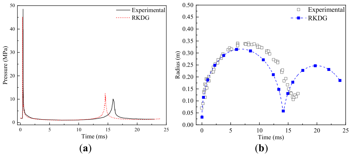
Figure 2.
The free-field load generated by a 0.222 kg spherical RS211 charge at an equivalent water depth of 600 m and a stand-off distance of 2.0 m.
Figure 2.
The free-field load generated by a 0.222 kg spherical RS211 charge at an equivalent water depth of 600 m and a stand-off distance of 2.0 m.
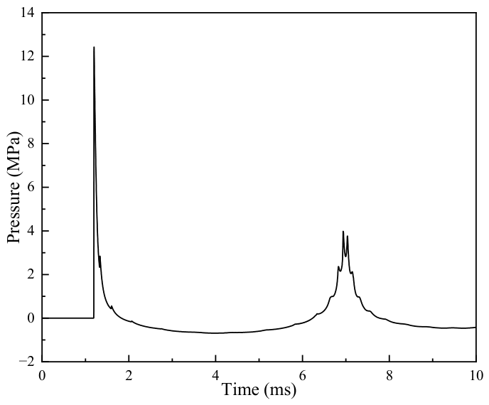
Figure 3.
The free-field loads generated by a 2 kg spherical RS211 charge under different water depths and stand-off distances: (a) Water depths of 1000, 1100, and 1200 m and a stand-off distance of 1.0 m; (b) Stand-off distances of 1.0 and 2.0 m at a water depth of 1000 m.
Figure 3.
The free-field loads generated by a 2 kg spherical RS211 charge under different water depths and stand-off distances: (a) Water depths of 1000, 1100, and 1200 m and a stand-off distance of 1.0 m; (b) Stand-off distances of 1.0 and 2.0 m at a water depth of 1000 m.
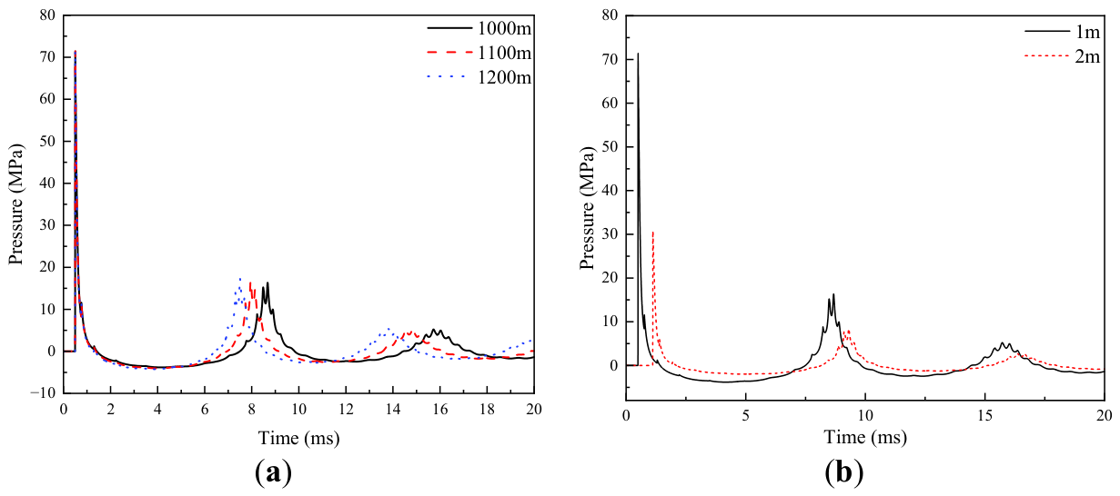
Figure 4.
Schematic diagram of the deep-water explosion test arrangement in the pressure tank.
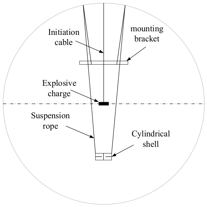
Figure 5.
Geometrical configuration, dimensions and photograph of the experimental stiffened cylindrical shell: (a) Geometrical configuration and dimensions; (b) Photograph.
Figure 5.
Geometrical configuration, dimensions and photograph of the experimental stiffened cylindrical shell: (a) Geometrical configuration and dimensions; (b) Photograph.
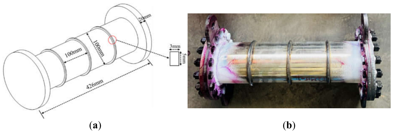
Figure 6.
Schematic diagram of strain and wall-pressure measuring point arrangement.
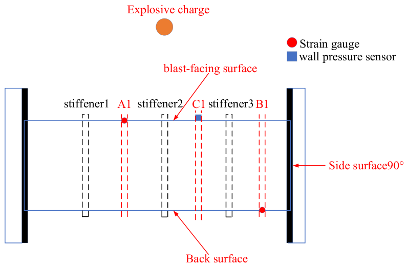
Figure 7.
Geometric model of the fluid domain and the stiffened cylindrical shell: (a) Fluid domain; (b) Stiffened cylindrical shell.
Figure 7.
Geometric model of the fluid domain and the stiffened cylindrical shell: (a) Fluid domain; (b) Stiffened cylindrical shell.
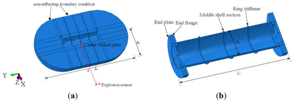
Figure 8.
Comparison of numerical and experimental wall-pressure histories on the explosion-facing surface.
Figure 8.
Comparison of numerical and experimental wall-pressure histories on the explosion-facing surface.
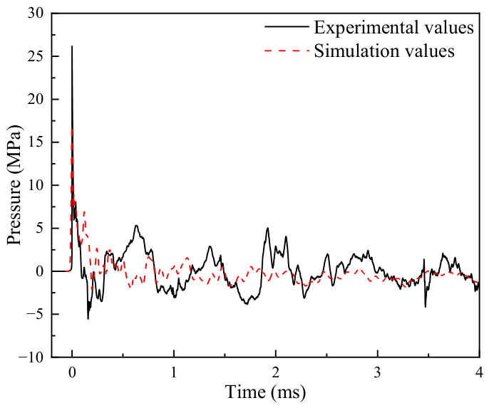
Figure 9.
Comparison of numerical and experimental circumferential strain histories: (a) Measuring point E1; (b) Measuring point E6.
Figure 9.
Comparison of numerical and experimental circumferential strain histories: (a) Measuring point E1; (b) Measuring point E6.
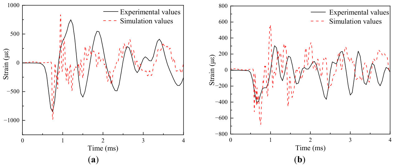
Figure 10.
Finite element model of the fluid domain and the stiffened cylindrical shell: (a) Fluid domain; (b) Stiffened cylindrical shell.
Figure 10.
Finite element model of the fluid domain and the stiffened cylindrical shell: (a) Fluid domain; (b) Stiffened cylindrical shell.
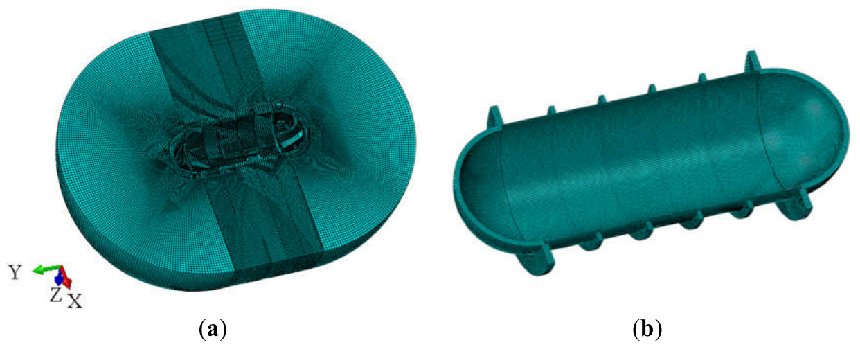
Figure 11.
Mesh-sensitivity analysis of the fluid domain and the stiffened cylindrical shell: (a) Pressure histories for different fluid-domain mesh sizes; (b) Deformation histories at the explosion-facing point for different structural mesh sizes.
Figure 11.
Mesh-sensitivity analysis of the fluid domain and the stiffened cylindrical shell: (a) Pressure histories for different fluid-domain mesh sizes; (b) Deformation histories at the explosion-facing point for different structural mesh sizes.
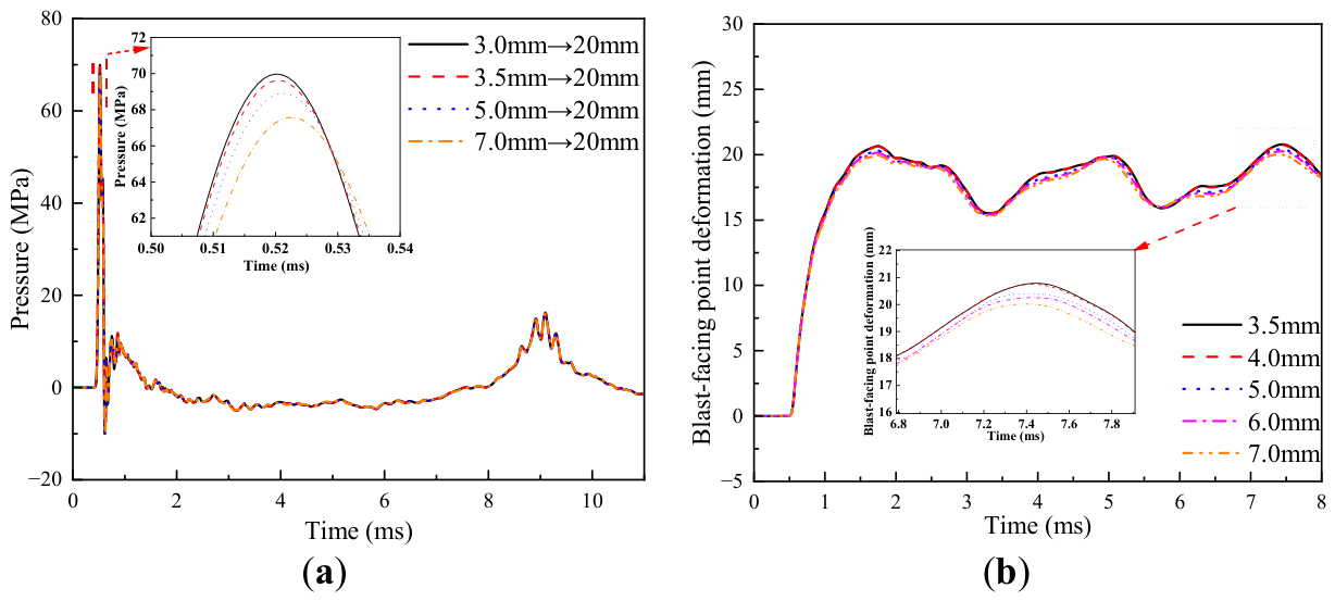
Figure 12.
Pressure histories at the fluid-structure coupling interface under different fluid-domain dimensions.
Figure 12.
Pressure histories at the fluid-structure coupling interface under different fluid-domain dimensions.
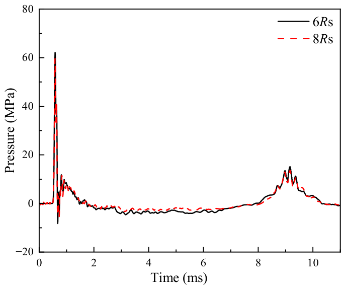
Figure 13.
von Mises stress contour of the cylindrical shell under 10 MPa hydrostatic pressure loading.
Figure 13.
von Mises stress contour of the cylindrical shell under 10 MPa hydrostatic pressure loading.
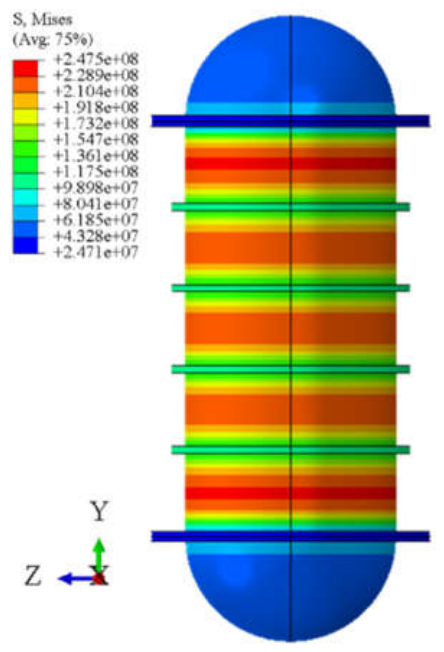
Figure 14.
Pressure contours in the water domain at different times: (a) 0.5 ms; (b) 0.7 ms; (c) 9.0 ms; (d) 10.0 ms.
Figure 14.
Pressure contours in the water domain at different times: (a) 0.5 ms; (b) 0.7 ms; (c) 9.0 ms; (d) 10.0 ms.
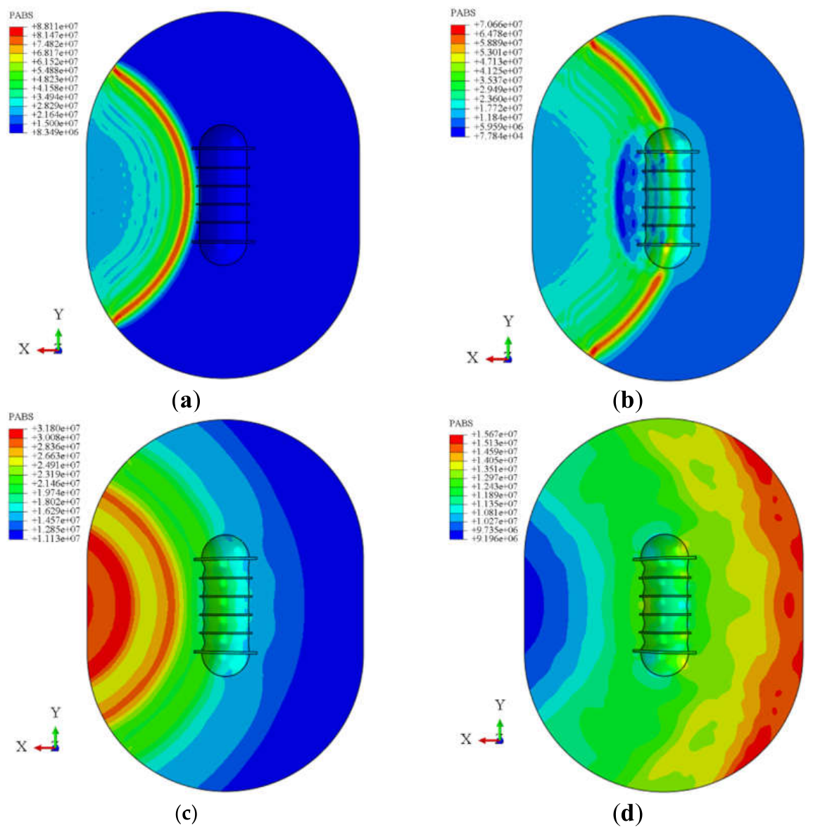
Figure 15.
Structural response contours during the shock-wave loading stage: (a) von Mises stress on the incident face at 1.0 ms; (b) von Mises stress on the leeward face at 1.0 ms; (c) von Mises stress on the incident face at 2.0 ms; (d) von Mises stress on the leeward face at 2.0 ms; (e) Displacement at 2.0 ms; (f) Equivalent plastic strain at 2.0 ms.
Figure 15.
Structural response contours during the shock-wave loading stage: (a) von Mises stress on the incident face at 1.0 ms; (b) von Mises stress on the leeward face at 1.0 ms; (c) von Mises stress on the incident face at 2.0 ms; (d) von Mises stress on the leeward face at 2.0 ms; (e) Displacement at 2.0 ms; (f) Equivalent plastic strain at 2.0 ms.
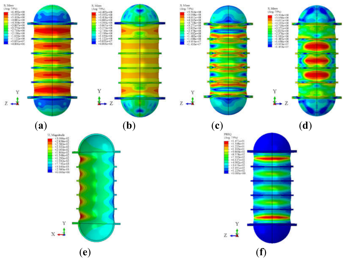
Figure 16.
Structural response contours during the bubble-pulsation loading stage: (a) von Mises stress on the incident face at 9.0 ms; (b) von Mises stress on the leeward face at 10.0 ms; (c) Displacement at 9.0 ms; (d) Equivalent plastic strain at 10.0 ms; (e) von Mises stress on the incident face at 11.0 ms; (f) von Mises stress on the leeward face at 11.0 ms; (g) Displacement at 11.0 ms; (h) Displacement at 20.0 ms.
Figure 16.
Structural response contours during the bubble-pulsation loading stage: (a) von Mises stress on the incident face at 9.0 ms; (b) von Mises stress on the leeward face at 10.0 ms; (c) Displacement at 9.0 ms; (d) Equivalent plastic strain at 10.0 ms; (e) von Mises stress on the incident face at 11.0 ms; (f) von Mises stress on the leeward face at 11.0 ms; (g) Displacement at 11.0 ms; (h) Displacement at 20.0 ms.
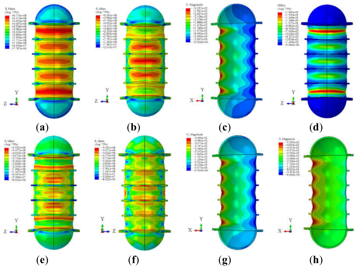
Figure 17.
Schematic diagram of monitoring point arrangement at typical locations: (a) Circumferential orientations of the monitoring points; (b) Relative axial positions of the monitoring points on the cylindrical shell.
Figure 17.
Schematic diagram of monitoring point arrangement at typical locations: (a) Circumferential orientations of the monitoring points; (b) Relative axial positions of the monitoring points on the cylindrical shell.
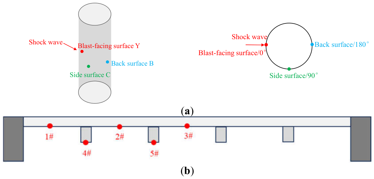
Figure 18.
Time-history curves of flow-field pressure and structural responses at typical locations on the incident face of the cylindrical shell: (a) Flow-field pressure; (b) von Mises stress; (c) Equivalent plastic strain; (d) Radial deformation.
Figure 18.
Time-history curves of flow-field pressure and structural responses at typical locations on the incident face of the cylindrical shell: (a) Flow-field pressure; (b) von Mises stress; (c) Equivalent plastic strain; (d) Radial deformation.
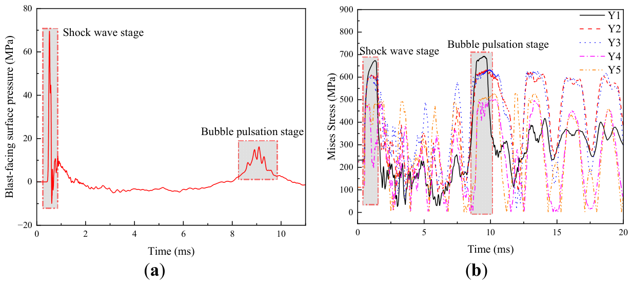
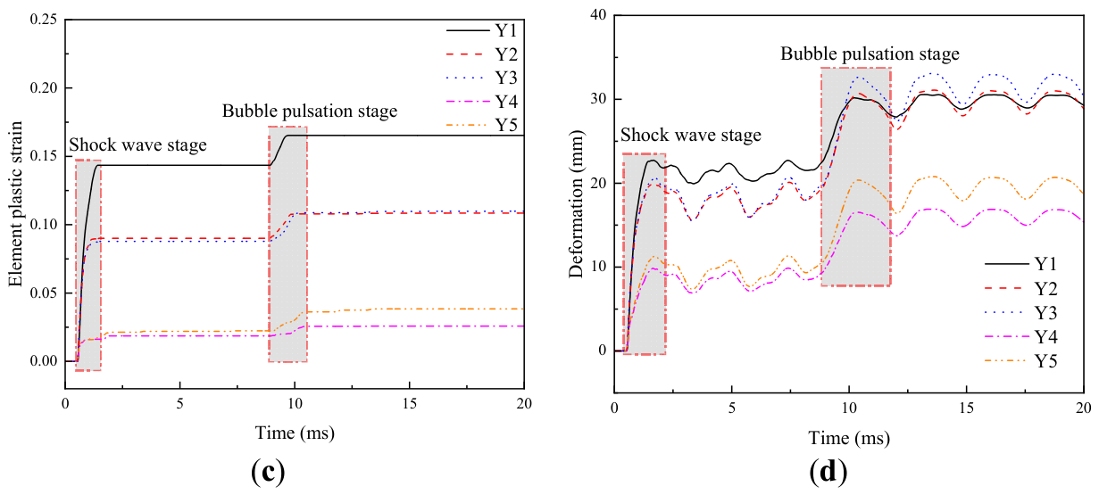
Figure 19.
Dynamic responses of the cylindrical shell at different circumferential orientations: (a) Deformation time histories; (b) Strain frequency-response curves.
Figure 19.
Dynamic responses of the cylindrical shell at different circumferential orientations: (a) Deformation time histories; (b) Strain frequency-response curves.
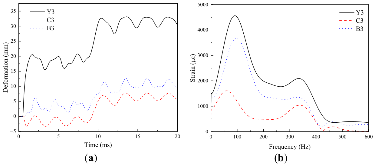
Figure 20.
Structural responses at the incident point of the cylindrical shell under different water depths: (a) von Mises stress histories; (b) Deformation histories.
Figure 20.
Structural responses at the incident point of the cylindrical shell under different water depths: (a) von Mises stress histories; (b) Deformation histories.
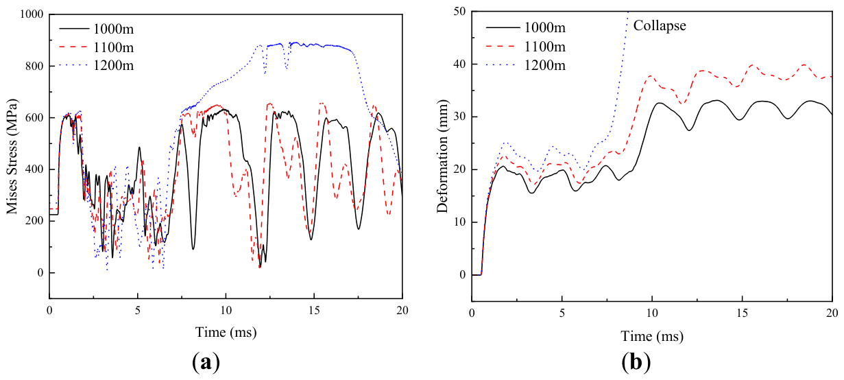
Figure 21.
Displacement contour at t = 11 ms under a water depth of 1200 m.
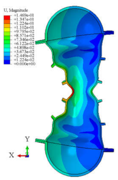
Figure 22.
Deformation energy of the cylindrical shell under different water depths.
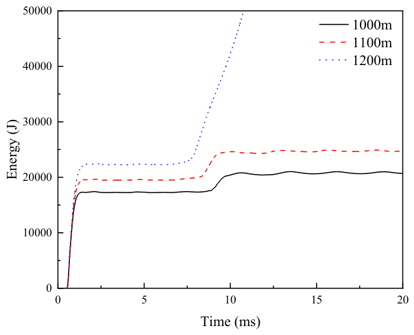
Figure 23.
Stress and strain histories of the cylindrical shell under different stand-off distances: (a) Stress at R = 2.0 m; (b) Strain at R = 2.0 m; (c) Stress at R = 1.0 m; (d) Strain at R = 1.0 m.
Figure 23.
Stress and strain histories of the cylindrical shell under different stand-off distances: (a) Stress at R = 2.0 m; (b) Strain at R = 2.0 m; (c) Stress at R = 1.0 m; (d) Strain at R = 1.0 m.
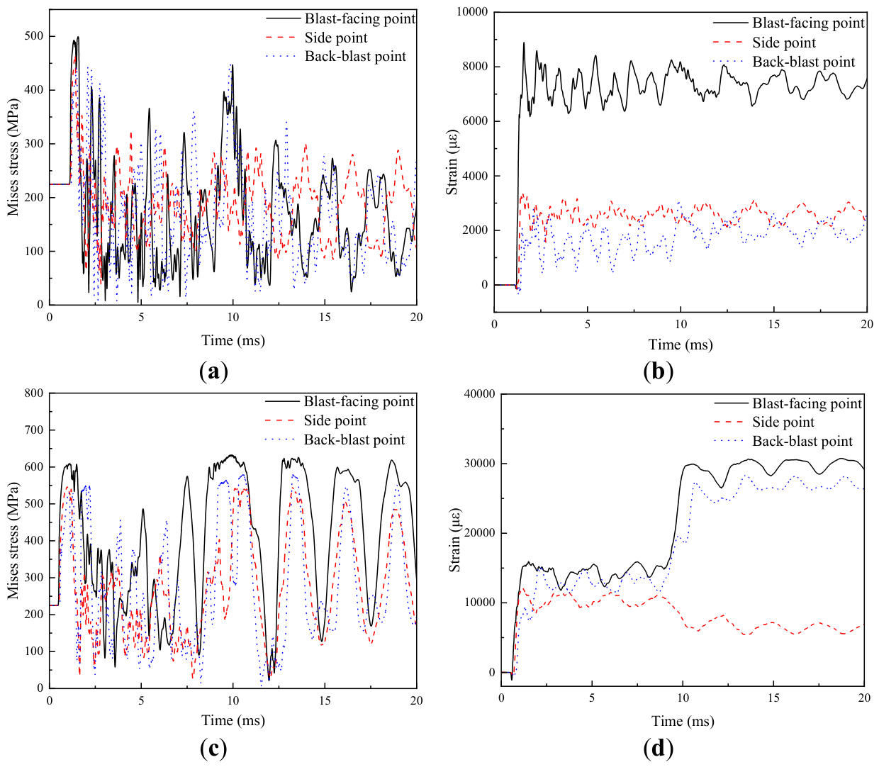
Figure 24.
Structural deformation responses under different stand-off distances: (a) Radial deformation histories of the incident face; (b) Displacement contour at t = 10 ms for R = 2.0 m.
Figure 24.
Structural deformation responses under different stand-off distances: (a) Radial deformation histories of the incident face; (b) Displacement contour at t = 10 ms for R = 2.0 m.
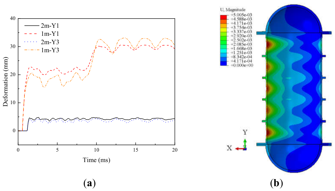
Figure 25.
Deformation energy and kinetic energy of the cylindrical shell.
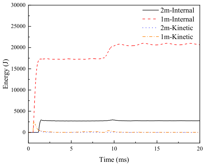
Figure 26.
Equivalent plastic strain contours of cylindrical shells with different shell thicknesses: (a) 6 mm; (b) 7 mm; (c) 8 mm; (d) 9 mm; (e) 10 mm.
Figure 26.
Equivalent plastic strain contours of cylindrical shells with different shell thicknesses: (a) 6 mm; (b) 7 mm; (c) 8 mm; (d) 9 mm; (e) 10 mm.
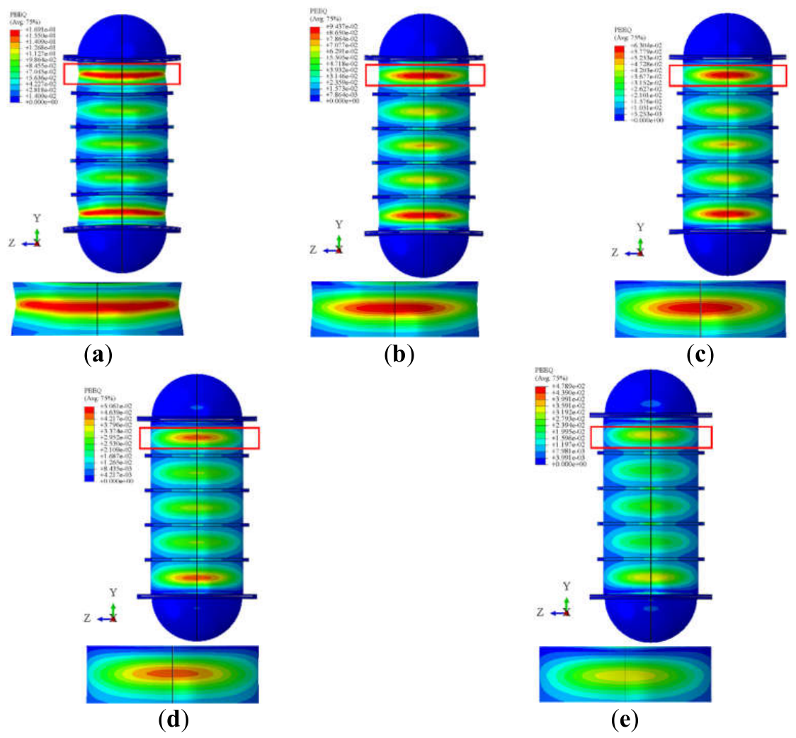
Figure 27.
Deformation responses of cylindrical shells with different shell thicknesses: (a) Deformation time histories; (b) Maximum radial deformation.
Figure 27.
Deformation responses of cylindrical shells with different shell thicknesses: (a) Deformation time histories; (b) Maximum radial deformation.
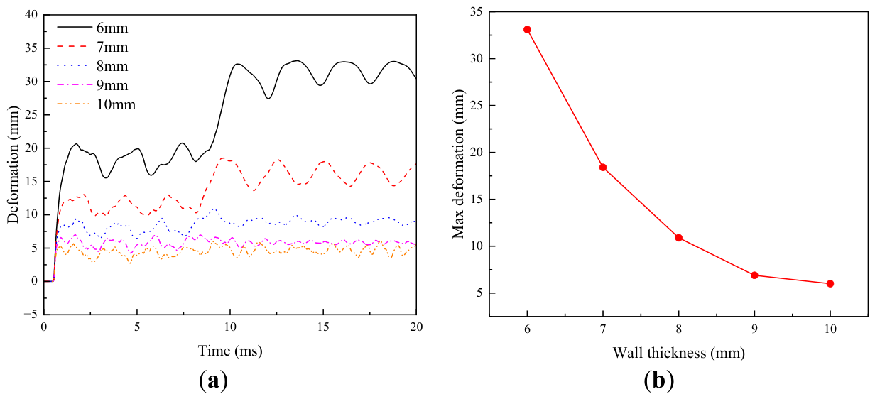
Figure 28.
Equivalent plastic strain contours of cylindrical shells with different numbers of ring stiffeners: (a) One ring stiffener; (b) Two ring stiffeners; (c) Three ring stiffeners; (d) Four ring stiffeners; (e) Five ring stiffeners.
Figure 28.
Equivalent plastic strain contours of cylindrical shells with different numbers of ring stiffeners: (a) One ring stiffener; (b) Two ring stiffeners; (c) Three ring stiffeners; (d) Four ring stiffeners; (e) Five ring stiffeners.
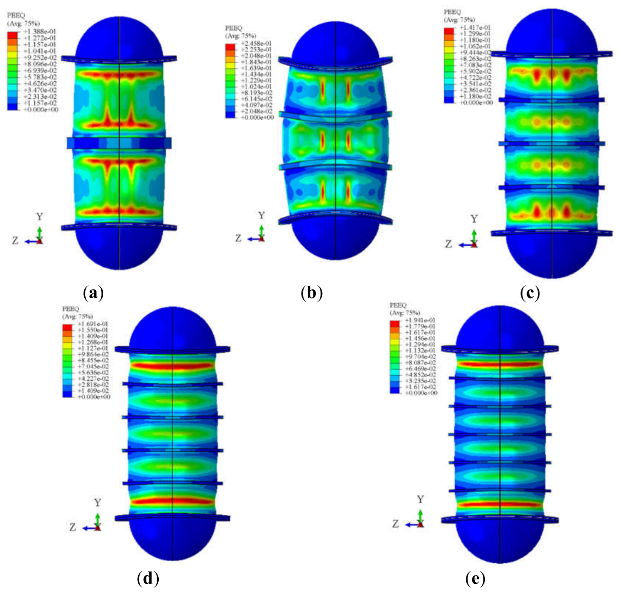
Figure 29.
Displacement contours of cylindrical shells with different numbers of ring stiffeners: (a) One ring stiffener; (b) Two ring stiffeners; (c) Three ring stiffeners; (d) Four ring stiffeners; (e) Five ring stiffeners.
Figure 29.
Displacement contours of cylindrical shells with different numbers of ring stiffeners: (a) One ring stiffener; (b) Two ring stiffeners; (c) Three ring stiffeners; (d) Four ring stiffeners; (e) Five ring stiffeners.
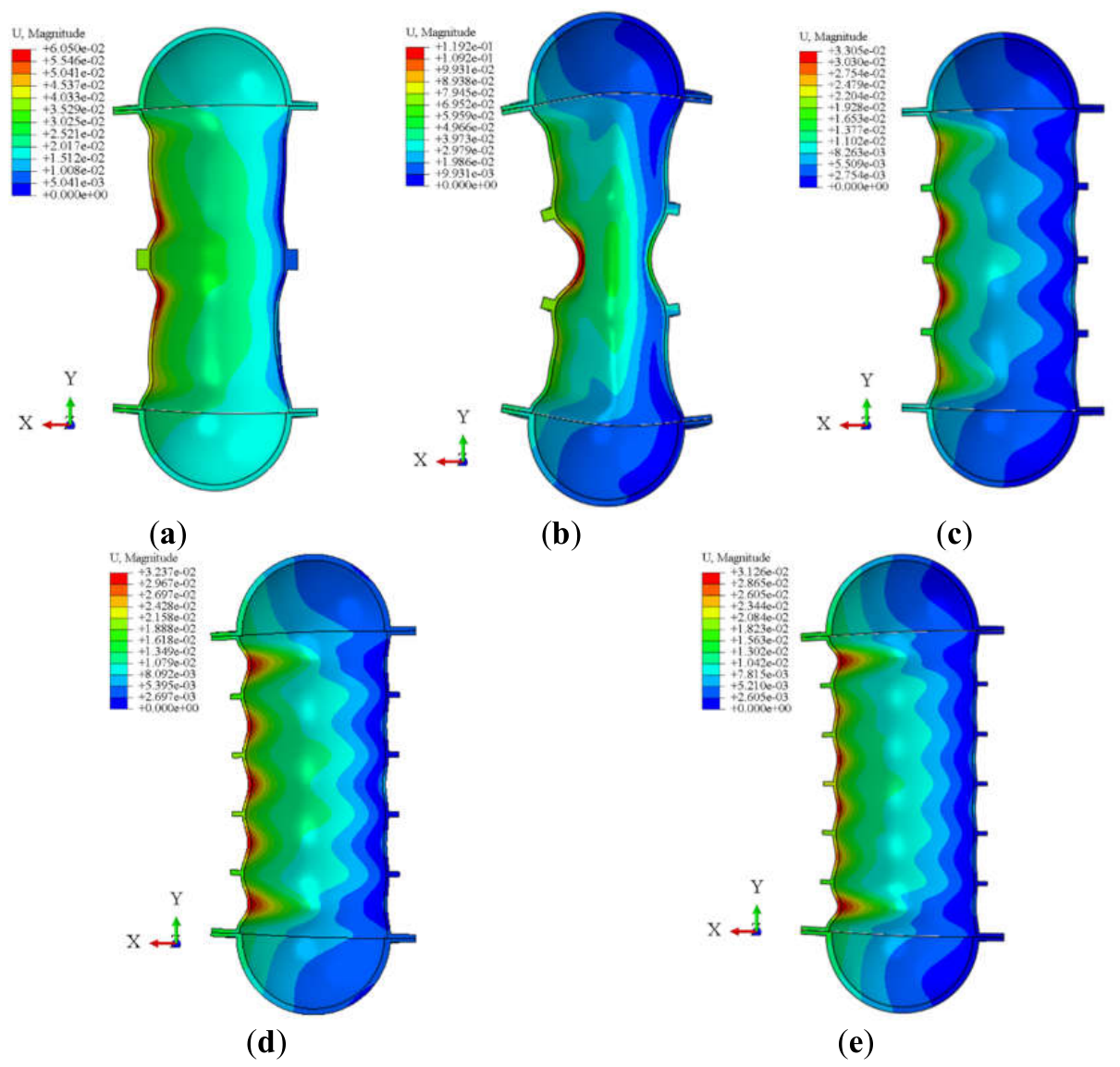
Figure 30.
Three-dimensional surface plots of the overall incident-face response of cylindrical shells with different numbers of ring stiffeners: (a) One ring stiffener; (b) Two ring stiffeners; (c) Three ring stiffeners; (d) Four ring stiffeners; (e) Five ring stiffeners.
Figure 30.
Three-dimensional surface plots of the overall incident-face response of cylindrical shells with different numbers of ring stiffeners: (a) One ring stiffener; (b) Two ring stiffeners; (c) Three ring stiffeners; (d) Four ring stiffeners; (e) Five ring stiffeners.
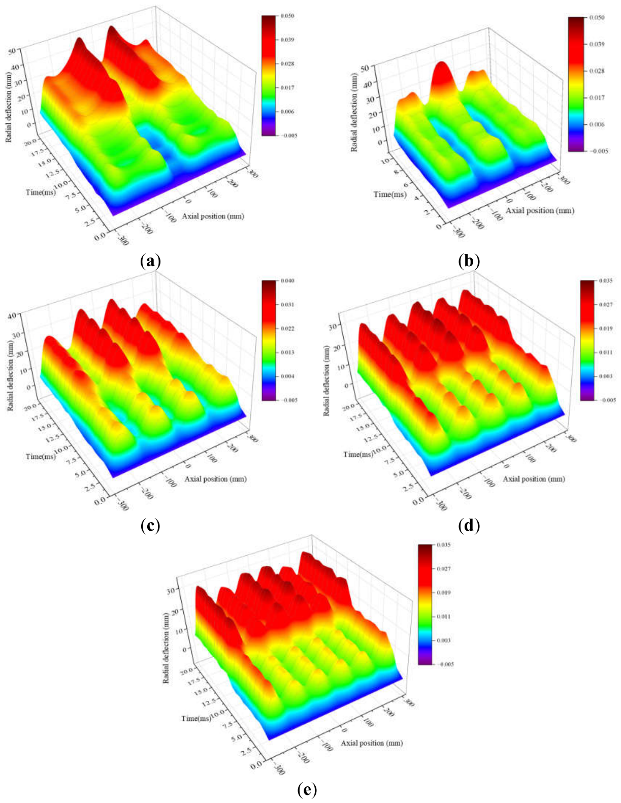
Figure 31.
Deformation energy time histories of cylindrical shells with different numbers of stiffeners.
Figure 31.
Deformation energy time histories of cylindrical shells with different numbers of stiffeners.
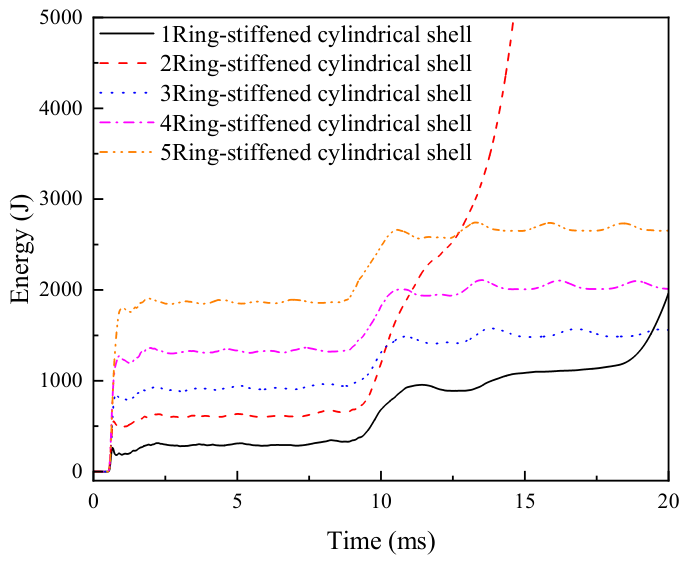

Table 1.
Parameters of the JWL equation of state.
| ρc0 (kg/m3) | A (GPa) | B (GPa) | R1 | R2 | ω | ec0 (MJ/kg) | |
|---|---|---|---|---|---|---|---|
| TNT [44] | 1630 | 373.8 | 3.75 | 4.15 | 0.9 | 0.35 | 3.68 |
| RS211 [45] | 1750 | 758.0 | 8.51 | 4.90 | 1.1 | 0.20 | 6.20 |
Table 2.
Johnson-Cook constitutive parameters of Q355 steel [48].
Table 2.
Johnson-Cook constitutive parameters of Q355 steel [48].
| ρs (kg/m3) | Es (GPa) | ν | As (MPa) | Bs (MPa) | n | m | Cs | Quasi-static strain rate s-1 |
|---|---|---|---|---|---|---|---|---|
| 7850 | 206 | 0.3 | 355.18 | 690.64 | 0.5038 | 0.8 | 0.0092 | 0.001 |
Table 3.
Meshing schemes.
| Meshing schemes | Structural mesh size /mm | Number of structural elements | Fluid mesh size /mm | Number of fluid elements | Fluid-domain radius |
| Scheme 1 | 4.0 | 131,928 | 3.0→20 | 4,651,956 | 6Rs |
| Scheme 2 | 4.0 | 131,928 | 3.5→20 | 3,389,960 | 6Rs |
| Scheme 3 | 4.0 | 131,928 | 5.0→20 | 2,174,940 | 6Rs |
| Scheme 4 | 4.0 | 131,928 | 7.0→20 | 1,510,604 | 6Rs |
| Scheme 5 | 3.5 | 168,668 | 3.5→20 | 3,389,960 | 6Rs |
| Scheme 6 | 4.0 | 131,928 | 3.5→20 | 3,389,960 | 6Rs |
| Scheme 7 | 5.0 | 73,658 | 3.5→20 | 3,389,960 | 6Rs |
| Scheme 8 | 6.0 | 47,742 | 3.5→20 | 3,389,960 | 6Rs |
| Scheme 9 | 7.0 | 34,416 | 3.5→20 | 3,389,960 | 6Rs |
| Scheme 10 | 4.0 | 131,928 | 3.5→20 | 6,060,744 | 8Rs |
(Note: Rs = 0.15 m denotes the radius of the cylindrical shell; the fluid-domain mesh size “X → 20” indicates a gradual transition from X mm in the near field to 20 mm in the far field.).
Disclaimer/Publisher’s Note: The statements, opinions and data contained in all publications are solely those of the individual author(s) and contributor(s) and not of MDPI and/or the editor(s). MDPI and/or the editor(s) disclaim responsibility for any injury to people or property resulting from any ideas, methods, instructions or products referred to in the content. |
© 2026 by the authors. Licensee MDPI, Basel, Switzerland. This article is an open access article distributed under the terms and conditions of the Creative Commons Attribution (CC BY) license (http://creativecommons.org/licenses/by/4.0/).
Copyright: This open access article is published under a Creative Commons CC BY 4.0 license, which permit the free download, distribution, and reuse, provided that the author and preprint are cited in any reuse.