

Submitted:
18 August 2026
Posted:
18 August 2026
You are already at the latest version
Abstract
Wellbore attitude and trajectory are critical parameters for complex oil and gas drilling and geosteering. As global energy exploration extends to deep earth, deep water, and unconventional resources, higher demands are imposed on downhole navigation accuracy and real-time performance. This paper reviews the development status and future trends of wellbore attitude and trajectory measurement technologies. Attitude measurement mechanisms based on magnetometers and gyroscopes are comparatively analyzed, along with their respective research focuses. Recent advances in magnetic interference compensation and accuracy enhancement for magnetometer-based schemes are summarized. Differences in attitude determination algorithms between reduced and full gyroscopes configurations are compared, and the common issue of performance degradation in near-vertical sections due to reduced accelerometer SNR is examined via numerical simulation. For trajectory measurement, traditional discrete reconstruction methods and their station-interval-induced accuracy limitations are evaluated, highlighting the urgent need for a transition from static discrete to dynamic continuous measurement. Strapdown inertial navigation based real-time estimation methods are discussed, with error propagation characteristics analyzed. Kinematic constraints such as depth increments and zero-velocity updates are identified as effective means to mitigate inertial error divergence. Finally, future prospects are outlined, emphasizing that an integrated “underground positioning system” leveraging AI, quantum sensing, and multi-sensor fusion will be key to enabling intelligent drilling measurement and control.
Keywords:
wellbore attitude
; wellbore trajectory
; inertial navigation
; magnetometer
; gyroscope
1. Introduction
Wellbore attitude and trajectory are critical parameters for decision-making in directional drilling and geosteering. As global energy demand shifts toward deep-earth, deep-water, and unconventional oil and gas resources, cluster wells, extended-reach wells, and deep wells have gradually become common well types in oil and gas resource development. These complex well types impose higher requirements on wellbore attitude measurement and trajectory control. Wellbore attitude and trajectory measurement runs through all stages of oil and gas well development. For example, in the wellpath design stage, wellbore attitude serves as the fundamental parameter for trajectory design [1]. During the drilling operation phase, in measurement, trajectory correction, and anti-collision operations, wellbore attitude parameters are typically transmitted uphole to the surface system via downhole communication systems. The surface software then analyzes drilling quality, evaluates drilling safety, and compares the deviations from the preset trajectory [2]. In the casing and completion phase, a follow-up survey of the wellbore orientation is usually conducted to obtain more precise positional parameters [3].
Two types of instruments are commonly employed for wellbore attitude measurement during oil and gas well development: wireline cable inclinometer and wireless measurement while drilling (MWD). The operating principle of the wireline cable inclinometer is schematically depicted in Figure 1. A surface winch lowers the inclinometer into the wellbore via a cable, and during the running-in process, the inclinometer continuously records wellbore attitude parameters, including inclination angle, azimuth angle, and toolface angle. Simultaneously, the depth is registered in real time by the reel mounted on the winch. By establishing a spatiotemporal alignment between the depth readings and the attitude measurements, the wellbore trajectory can be reconstructed and plotted.
Wireless MWD measure wellbore attitude during drilling operations through wireless telemetry methods such as mud pulse transmission [4]. As illustrated in Figure 2, the MWD is positioned within the drill collar immediately behind the drill bit, forming the MWD system together with the communication module. When a certain depth interval has been drilled and a survey station is reached, a command is issued from the surface system, and the drilling process is typically paused for several minutes to conduct azimuth measurements. Upon completion of the measurement, the mud pulse telemetry module is activated to transmit the wellbore attitude data to the surface software platform [5]. The wellbore trajectory is reconstructed by the surface software through the integration of wellbore attitude measurements at each survey station and the corresponding well depths between adjacent stations, with the latter being predominantly governed by the drill pipe length.
Two types of sensor configurations are commonly employed for wellbore attitude measurement: one utilizing a magnetometer combined with accelerometers, and the other employing a gyroscope in conjunction with accelerometers. In the former configuration, the reference for azimuth measurement is the magnetic north, whereas in the latter, the reference is the geographic north. The magnetometer is susceptible to magnetic interference and therefore requires periodic compensation and calibration. When hard-iron or soft-iron magnetic disturbances are present in the wellbore measurement environment, the magnetometer becomes inoperative, and the gyroscope must be relied upon to perform azimuth measurements [6]. The gyroscopes applied in oil and gas well development can be further categorized into mechanical gyroscopes, Micro-Electro-Mechanical System (MEMS) gyroscopes, and fiber optic gyroscopes. Gyroscopes with solid-state packaging characteristics, such as optical gyroscopes, are better suited to withstand the downhole mechanical environment [7]. However, they face challenges in adapting to high-temperature or ultra-high-temperature operating conditions. Table 1 summarizes the typical wellbore attitude measurement accuracies achieved under various sensor configuration schemes. The azimuth accuracy and toolface accuracy specified in the table are generally constrained to conditions where the inclination angle is greater than 3°, because in near-vertical states (inclination angle less than 3°), the signal-to-noise ratio of the radial accelerometers degrades significantly, leading to a substantial reduction in accuracy. In near-vertical well sections, magnetic toolface or gyro toolface is typically used for orientation purposes. This issue will be further analyzed in the following sections.
Wellbore attitude angles are critical parameters for drill bit trajectory control and wellbore trajectory measurement. The depth intervals between successive survey stations recorded during the drilling process, when combined with azimuth and inclination angles, enable the determination of positional offsets in each direction [9]. The accuracy of trajectory measurement is influenced not only by the precision of attitude angles but also by systematic drilling errors and environmental disturbances [10]. Since the propagation mechanisms of various error sources cannot be accurately described mathematically during the drilling process, wellbore trajectory uncertainty analysis theory is introduced to constrain the error bounds of the trajectory [11]. In technical workflows such as wellpath design, wellbore trajectory measurement, and wellbore trajectory prediction, the trajectory error ranges in all directions are taken into consideration to mitigate operational risks such as the inability of the drilling assembly to reach the target reservoir [12].
This paper presents a comprehensive review of the current state of wellbore attitude and trajectory measurement technologies in the field of oil and gas drilling. Proceeding from the measurement principles, the technical characteristics and research directions of wellbore attitude measurement methods based on different sensor configurations are discussed. In conjunction with the engineering application characteristics of wellbore trajectory measurement technologies, the theoretical framework and development trends of trajectory measurement in oil and gas drilling are systematically elaborated. The remainder of this paper is organized as follows. Section 2 introduces the principles of wellbore attitude measurement and discusses the current research status, as well as the advantages and disadvantages, of two types of sensors—magnetometers and gyroscopes—in wellbore attitude measurement. Section 3 presents the measurement principles and technical features of conventional discrete trajectory reconstruction methods and analyzes the feasibility of continuous wellbore trajectory measurement. Section 4 provides an outlook on future development directions of wellbore attitude and trajectory measurement technologies. Section 5 concludes this paper.
2. Wellbore Attitude Measurement Technology
Wellbore attitude angles essentially refer to the Euler angles between the downhole tool coordinate system and the reference coordinate system, namely inclination (inc), azimuth (az), and toolface angle (tf). These angles can accurately indicate the tool orientation, deviation, and the angle between the bit deflection direction and the plane containing the tool axis (i.e., tf). Under ideal conditions, when the tool axis is parallel to the wellbore axis, the tool orientation and deviation can approximately characterize the wellbore course. Therefore, the tool attitude angles are conventionally referred to as wellbore attitude angles in the industry. A spatial illustration of the wellbore attitude angles is shown in Figure 3.
Inclination is defined as the angle between the tool axis and the vertical (plumb line), ranging from 0° to 90°, with an inclination of 0° corresponding to a vertical tool. Azimuth is the angle between the horizontal projection of the tool axis and the north direction, measured clockwise from north (eastward positive), ranging from 0° to 360°. Gravity toolface is the angle between the high-side direction and a designated reference line on the radial plane of the tool, ranging from 0° to 360°. In near-vertical conditions, the angle between the reference line and the magnetic north (or true north) is used as an approximation, which is termed magnetic toolface (mtf) or gyro toolface (gtf).
2.1. Magnetometer-Based Wellbore Attitude Measurement Method
The magnetometer, which is sensitive to the strength and direction of the Earth’s weak magnetic field, represents the earliest vector sensor applied to wellbore attitude measurement. The magnetometer probe features a robust physical structure capable of withstanding vibration and shock loads encountered during drilling operations. In addition, the magnetometer exhibits low power consumption, making it suitable for prolonged operation within the confined downhole space. In a magnetically undisturbed environment, it can be combined with accelerometers to achieve high-precision azimuth measurements. The governing equations for wellbore attitude calculation are presented as
where and denote the accelerometer outputs along the x-axis and z-axis, respectively; is the gravitational acceleration constant; and, and represent the magnetometer outputs along each axis. It can be observed from the above equations that inc and tf are primarily determined by the three-axis accelerometer. In inertial navigation terminology, these two angles are also referred to as horizontal angles, corresponding to the pitch and roll angles of an aircraft [13]. Only after the navigation horizontal plane is established by the carrier can the projection of the flight direction onto the horizontal plane be accurately computed, thereby enabling the determination of the angle relative to true north or magnetic north.During drilling or logging operations, mtf or gtf is typically utilized as a substitute for gravity toolface when the instrument is in a near-vertical attitude. This is because, under near-vertical conditions, the radial accelerometer components used for toolface determination approach “0g,” resulting in accuracy degradation, which in turn adversely affects the azimuth calculation.
Ideally, the measurement accuracy of magnetometer azimuth is far higher than practical engineering requirements. However, significant soft-iron or hard-iron interference usually exists in downhole environments. For example, ferromagnetic materials from casings in shallow or adjacent wellbore can introduce additional interference magnetic fields; meanwhile, drill string materials, downhole circuit systems, and metallic minerals in formations during drilling can also generate time-varying interference magnetic fields [14]. Therefore, research on magnetometer-based wellbore attitude measurement technology mostly focuses on the compensation and calibration of magnetometers to improve azimuth measurement accuracy [15,16]. Hard-iron interference manifests as a fixed offset superimposed on each axis output, whereas soft-iron interference affects the scale factor and orthogonality of the magnetometer. The general form of the magnetometer error model is shown in Equation (2).
In Equation (2), represents the actual output of each axis sensor, with the superscript s denoting the sensor coordinate frame; represents the accurate value after error compensation, with the superscript b denoting the body coordinate frame used for subsequent attitude navigation. The diagonal elements of matrix correspond to the scale factor errors induced by soft-iron effects, while the non-diagonal elements represent the non-orthogonality errors caused by soft-iron interference. denotes the zero-bias error resulting from hard-iron interference. Existing research efforts on magnetometer error compensation methods are built upon this error model.
To ensure accurate error compensation for the magnetometer, a common traditional method involves fixing the instrument on a non-magnetic three-axis turntable [17,18]. By sampling the sensor outputs across multiple orientations and combining them with methods like least squares or polynomial fitting, all 12 error terms in the equation can be solved. Although this type of method demands strict experimental environments and is time-consuming, it can accurately compensate for each individual error term, and remains widely adopted in current engineering applications.
Another class of methods involves capturing sensor outputs in all directions by rotating the magnetometer, from which an ellipsoid equation containing error coefficients is derived based on the general magnetometer error model [19,20]. However, the general expression of an ellipsoid contains only 9 coefficients. To address this issue, the matrix is constrained to an upper or lower triangular form, reducing the soft-iron error parameters to 6. This approach is a widely used online error calibration technique known as the ellipsoid fitting(EF)—a scalar calibration technique based on the principle of magnitude invariance of the magnetic field vector. The general form of the triaxial magnetometer ellipsoid can be expressed as:
In the above equation, the matrix R containing non-orthogonality and scale factor error terms, as well as the matrix b representing the bias parameters for each axis, can be solved from the coefficients . The core of this mathematical-analytical error compensation method lies in establishing an accurate error model and acquiring sufficient sensor data in all directions to enable a more precise estimation of the error parameters.
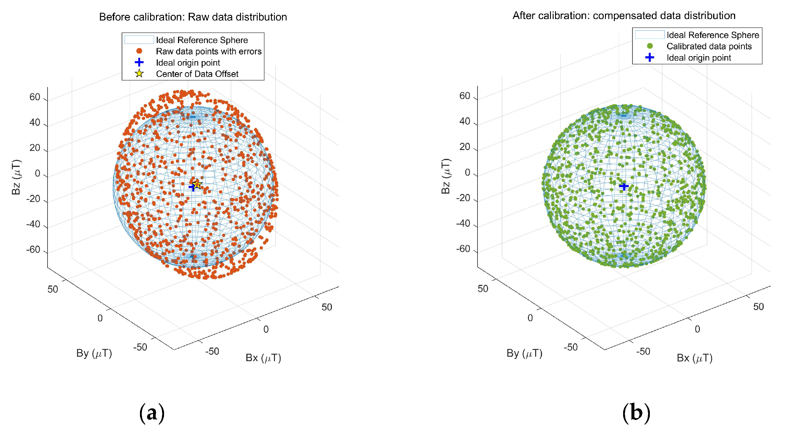
Figure 4 illustrates a comparison of the data distribution of the triaxial magnetometer before and after error compensation using the ellipsoid fitting method. Non-orthogonality errors in the triaxial magnetometer induce distortion in the generated 3D ellipsoid; scale factor errors cause the data range along a specific axis to deviate from the ideal value; and zero-bias errors shift the center of the ellipsoid away from the coordinate origin. During the fitting process, the raw data should be uniformly distributed across all spatial directions to ensure that the least squares method can estimate the error parameters with higher accuracy.
Addressing ellipsoid fitting and static multi-position calibration techniques, numerous researchers have devoted efforts to algorithmic and theoretical innovations aimed at estimating triaxial magnetometer errors more accurately, thereby enhancing orientation measurement precision. Accelerometers integrated within inclinometers or MWD systems serve as effective auxiliary calibration tools. Given the spatial vector invariance between the gravity field and geomagnetic field measured by accelerometers and magnetometers, respectively, an error model based on the vector product between these two sensors can be established. This model, combined with multi-position static data sampling, enables the estimation of magnetometer errors [21]. Leveraging the invariant angle between the local gravity vector and the magnetic field vector, Yu, H., et al. proposed a novel in-field calibration method called “Inclination-based Calibration” (I-Calibration) [22]. This method reliably estimates magnetometer model parameters using solely a linear least-squares estimator. In this workflow, accelerometer errors are calibrated first; subsequently, in a magnetically clean environment, the calibrated accelerometer acts as a reference baseline to solve for error parameters using numerical methods such as Newton-Raphson iteration or least-squares estimation. Considering downhole operating temperature ranges, Hu et al. established individual sensor and thermal error models and proposed a calibration methodology based on a full-field calibration algorithm, least-squares estimation, and a transfer-matrix model [23]. This approach computes calibration parameters at ambient temperature efficiently and provides an algorithm for deriving temperature coefficients over the target range.For inclinometers composed of gyroscopes, accelerometers, and magnetometers, magnetometer calibration can also leverage the invariants among these three vector fields—provided the gyroscope accurately senses Earth’s rotation rate. For instance, Ji S, et al. utilize Fiber Optic Gyroscopes (FOGs) to assist in calibrating magnetometers. Because magnetized magnetometers exhibit significant errors, leveraging the calibration-free nature of FOGs serves as a viable pathway for online/in-situ calibration [24]. Furthermore, to enable real-time error compensation during operations, Multi-Station Analysis (MSA) has emerged as a typical method in drilling and logging applications. MSA combines sensor data from multiple downhole static survey stations for online error correction, thereby improving wellbore azimuth measurement accuracy [25]. Beyond magnetometer calibration, MSA is also widely applied in evaluating wellbore trajectory uncertainties and optimizing well path placement [26,27].
During drilling and logging operations, errors introduced by environmental noise similarly restrict the accuracy of wellbore attitude measurements. To address this issue, a common strategy involves sensor noise reduction techniques to diminish the magnitude of attitude error. Combining radial accelerometers at the bit end with an axial MEMS gyroscope, Wang W, et al. adopted a nonlinear Complementary Filter (CF) to suppress vibration acceleration impacts, thereby enhancing toolface angle accuracy during dynamic drilling [28]. To improve the precision of inclination measurements in dynamic environments, Yang et al. utilized the periodic characteristics of magnetometer signals—which remain unaffected by shock and vibration—and proposed an Unscented Kalman Filter (UKF) algorithm tailored for mitigating colored noise in accelerometer outputs [29]. Recognizing that geomagnetic component measurements directly affect downhole tool azimuth and magnetic toolface angles, Li et al. proposed a Zonotopic Kalman Filter (ZKF)-based state estimation framework for geomagnetic components and attitude determination [30]. By incorporating the rotational constraint characteristics of Rotary Steerable Systems (RSS), Xue et al. constructed a novel state-space model that leverages the periodic rotation of magnetometers and accelerometers as measurement updates. This KF-based method achieves continuous azimuth measurement, simultaneously boosting wellbore attitude accuracy and effectively dampening drill-string-induced errors [31]. Furthermore, Liu et al. employed an optics clustering algorithm to filter out noise spikes in magnetometer and accelerometer readings, subsequently combining an improved Multi-Station Analysis (MSA) with a Gaussian Process Regression (GPR) model to suppress cross-axis magnetic interference and nonlinear noise [32]. This three-stage strategy effectively enhances magnetic azimuth accuracy under complex magnetic environments.
The evolution of artificial intelligence (AI) algorithms has significantly driven their applications in oil and gas well engineering. To enhance wellbore attitude precision, researchers have conducted extensive explorations centered on AI methodologies. Addressing challenges in drilling trajectory control caused by downhole attitude data loss and sensor noise, Liu et al. proposed a Long Short-Term Memory (LSTM) network model that successfully accomplishes data completion across acceleration and magnetic flux signals, thereby enabling robust sensor data reconstruction [33]. Integrating downhole tool attitude sensor data with machine learning techniques, Liu et al. performed signal inversion on accelerometer readings specifically for dynamic inclination measurement; by training on signal features across varying rotational speeds, the method achieved marked accuracy improvements in dynamic inclination under multi-speed operating conditions [34]. Combining empirical calibration data with measurement error characteristics, Yang et al. established a neural network model based on the K-proximity method to compensate for error components in MWD magnetometers and accelerometers, effectively upgrading the overall wellbore attitude accuracy of MWD systems [35]. Zhou et al. proposed a Backpropagation (BP) neural network-based algorithm for MWD installation error correction [36]. Bypasssing the need for explicit installation error modeling or supplementary parameter calculations, this approach directly predicts attitude angles via ellipsoid fitting of raw measurement data, thereby effectively mitigating the impact of misalignment errors.
The application of AI algorithms to improve wellbore trajectory accuracy still relies heavily on model precision. Training these model parameters requires large dataset samples, placing high demands on hardware performance. Restricted by downhole tool dimensions, power consumption, and hardware architecture, AI-based trajectory improvement methods face certain limitations in real-time on-tool implementation. Furthermore, AI algorithms currently focus more on optimizing data integrity across the entire drilling cycle and removing data outliers; further technical breakthroughs are still needed regarding direct improvements to wellbore trajectory accuracy. Currently, the mainstream engineering methods for enhancing wellbore trajectory accuracy remain focused on magnetic interference correction, magnetometer and accelerometer error calibration, and sensor noise reduction. However, when drilling through high magnetic interference zones (such as vertical or cluster well sections), gyroscopic survey tools must be relied upon to complete the measurement.
2.2. Gyro-Based Wellbore Attitude Measurement Method
Gyroscopes are widely used in vehicles, ships, aircraft, missiles, and other carriers, serving as core sensors for attitude measurement, control, navigation, and positioning. Gyroscope types can be classified into mechanical gyros, optical gyros, and MEMS gyros, with optical gyros further divided into ring laser gyros and fiber optic gyros. Table 2 provides the classification of each gyro type alongside an analysis of their applicability in oil and gas well engineering.
Mechanical gyroscopes incorporate internal high-speed rotors, making them highly susceptible to vibration and requiring absolute stationarity to achieve accurate azimuth measurements. Conversely, optical and MEMS gyroscopes—collectively termed solid-state gyroscopes—contain no moving parts, thereby broadening their operational versatility in wellbore trajectory measurement. Researchers have investigated wellbore trajectory measurement methods utilizing 9-axis sensor suites composed of MEMS inertial measurement unit(IMU) and magnetometers. In these integrated measurement architectures, magnetometers provide the initial attitude reference, while MEMS gyroscopes update quaternions or Euler angles in real time during dynamic operations to ensure continuous trajectory tracking. The algorithmic framework generally centers on a complementary filter scheme for integrated attitude determination [37,38].
Although ring laser gyroscopes (RLGs) offer high precision and serve as primary sensors for navigating large platforms (such as vessels and aircraft), their bulky physical footprint hinders integration into space-constrained drilling tools. As fiber optic gyroscope (FOG) fabrication techniques mature, medium-to-high-precision FOGs are increasingly miniaturized, enabling technological enhancements in both wireline gyro inclinometers and wireless gyro measurement-while-drilling (GMWD) systems. Extensive literature indicates that various FOG-based inclinometers and MWD systems have been successfully developed. For example, a research team at Beihang University developed FOG-based inclinometers with varied outer diameters that maintain absolute azimuth errors within 1°, fully satisfying conventional drilling requirements [39,40]. A standard FOG-MWD configuration integrates a triaxial FOG and a triaxial quartz flexural accelerometer to achieve full-attitude capability. However, its temperature tolerance remains a bottleneck, constraining its application primarily to shallow formations and vertical well sections [41,42,43].
Gyroscope-based wellbore attitude measurement methods and technologies are primarily developed within the methodology framework of inertial navigation systems (INS). During continuous measurement, the angular velocity component output by the gyroscope—after subtracting non-carrier rotational rate—tracks the attitude angles via quaternion updates. At static survey stations, the attitude matrix (Euler angle matrix) is derived using the dual-vector attitude determination principle to resolve attitude information. Within this mathematical framework, however, gyroscope and accelerometer errors inevitably couple into the attitude angles, causing error accumulation over time until divergence occurs. Under harsh drilling vibration environments, these sensor errors are further amplified, leading to severe measurement inaccuracies. Consequently, research efforts have largely focused on mitigating sensor error magnitudes in dynamic environments to improve attitude measurement precision.
Under the inertial navigation framework, Zhang et al. established a dynamic Allan variance-based noise model to improve the long-term measurement accuracy of fiber optic gyroscopes (FOGs) in MWD systems. This approach effectively suppresses vibration noise, yielding a 50% reduction in azimuth error under random vibration conditions [44]. Addressing the nonlinear dynamic errors of inertial sensors, Wang et al. proposed a 36th-order Extended Kalman Filter (EKF) error compensation model that effectively compensates for nonlinear error terms induced by periodic and random vibrations [45]. From the perspective of sensor signal processing, Yang et al. developed a Synergy-enhanced Magpie Optimizer (SMO) to mitigate drilling-induced gyroscope errors. This algorithm enables online identification of MEMS gyroscope error parameters and reduces error magnitude, though its specific enhancement on azimuth accuracy was not further validated [46]. To overcome the adverse impacts of high temperatures and mechanical shock on MEMS gyroscopes, Yan et al. introduced a signal processing and north-finding method utilizing a drift correction strategy, which significantly enhanced the azimuth accuracy of downhole inclinometers [47]. Furthermore, researchers have integrated algorithmic filtering with auxiliary hardware to estimate and compensate for sensor errors. Ursenbach et al. proposed an in-drilling alignment algorithm; however, it requires external auxiliary sensors to accurately measure axial displacement [48]. To tackle large positioning errors, Li et al. proposed an Augmented Fast Orthogonal Search/Kalman Filtering (FOS/KF) attitude estimation scheme, which improves accuracy but necessitates a rotation modulation motor for auxiliary measurement [49]. Drawing on the concept of rotational inertial navigation systems (RINS), Sha et al. designed a MEMS-based MWD architecture featuring a rotational modulation unit and an axial speed encoder, utilizing a Kalman filter for azimuth estimation [50]. Additionally, Yang et al. devised an equivalent reverse rotation modulation method coupled with a robust iterative filtering optimization scheme, accurately identifying gyroscope error parameters and improving wellbore trajectory measurement precision [51]. In summary, the key research methodologies for gyroscope-based wellbore attitude measurement are summarized in Table 3.
2.2.1. Wellbore Attitude Measurement via Reduced Inertial Measurement Unit
For inclinometers or MWD systems configured with a single-axis gyroscope, the underlying measurement principle is categorized within inertial navigation as north-seeking. Such systems typically consist of a single-axis gyroscope and a triaxial accelerometer—a configuration commonly employed in vehicle positioning and orientation. During ground transport, vehicles experience relatively small variations in pitch and roll; hence, determining only the heading angle is sufficient. To minimize hardware costs, this simplified architecture—known as a Reduced Inertial Measurement Unit (RIMU)—is adopted. The single-axis gyroscope is deployed to sense the angular velocity of Earth’s rotation, which necessitates a high-precision sensor grade. Using the two horizontal angles (inclination and gravity toolface angle) derived from the triaxial accelerometer, the angular velocity measured by the single-axis gyroscope is projected onto the horizontal plane. Because a trigonometric relationship exists between the north component of Earth’s rotation rate and the projected horizontal angular velocity, the azimuth angle can be explicitly resolved.
Assuming the instrument is in a completely horizontal state with a single-axis gyroscope aligned along the longitudinal tool axis (-axis), the angle between the tool axis and Geographic North represents the azimuth angle (az). The relationship between the gyroscope output and the projected component of Earth’s rotation rate is formulated as follows:
where denotes the actual output of the gyroscope, is Earth’s angular rotation rate, is the local geographic latitude, represents the north component of Earth’s rotation rate, is the residual gyro bias error, and denotes the measurement random noise. Solving the equation above yields the explicit expression for the azimuth angle as follows:
When utilizing a low-precision gyroscope, its azimuth measurement accuracy often deviates significantly from the true value due to the adverse impacts of gyro bias instability and random noise. Consequently, when deploying a single-axis gyroscope for wellbore trajectory measurement, multi-position indexing (indexing measurement schemes) is routinely implemented at survey stations to compensate for the online gyro bias error and enhance azimuth accuracy. Furthermore, when the instrument is in an inclined (non-horizontal) orientation, azimuth accuracy is additionally constrained by the measurement precision of the inclination and toolface angles. Under such conditions, the attitude transformation matrix from the body coordinate frame (-frame) to the navigation coordinate frame (-frame) is expressed as follows:
Incorporating the attitude transformation matrix, Equation (4) can be reformulated as follows:
where represents the vertical (upward) component of Earth’s angular rotation rate. Consequently, the explicit expression for the azimuth angle can be formulated as follows:
Azimuth accuracy is inherently constrained by inclination angle, toolface angle, and sensor errors; when the true angular velocity signal sensed by the gyroscope accounts for a low signal-to-noise ratio, calculation precision degrades significantly. Under conventional Euler angle definitions, the instrument orientation corresponds to an inclination angle in horizontal sections and in vertical sections. Consequently, resolving the azimuth under near-vertical conditions introduces a mathematical singularity into the azimuth formulation. Conversely, in horizontal well sections, the formulation simplifies directly to Equation (5), yielding the highest azimuth determination precision, albeit still governed by the residual gyro bias. Based on the sensor error parameters specified in Table 4, the simulated degradation trend of azimuth accuracy as the inclination decreases from to is illustrated in Figure 5.
The sensor accuracies listed in the table satisfy the operational precision requirements for wellbore attitude measurement. Because conventional inclination conditions do not induce azimuth accuracy degradation, Figure 5 depicts the calculated azimuth results only under selected low-inclination angles. The pronounced oscillation amplitude observed in the azimuth curves stems from the combined effects of random noise in both the accelerometers and the gyroscope. As the wellbore approaches a near-vertical state, the oscillation amplitude of the azimuth increases progressively. This degradation occurs because the horizontal projection component of Earth’s rotation sensed by the gyroscope becomes extremely weak under near-vertical conditions; when coupled with gyro random noise and residual bias error, it renders precise determination of the true heading impossible.
To counteract the impact of gyroscope errors and minimize the uncertainty inherent to a single-gyroscope configuration, multi-position indexing (north-seeking) schemes are routinely employed for azimuth determination. Taking a four-position scheme as an example, let denote the gyroscope output at the initial position. The corresponding gyroscope outputs obtained by sequentially rotating the tool about the vertical (Upward) axis by , , and are denoted as , and , respectively, as expressed below:
When the positions are separated by , subtracting the gyroscope outputs between the two opposing positions effectively cancels out the constant gyro bias error, yielding . Furthermore, these differential expressions can be reformulated as follows:
Combining the differential expressions above, the trigonometric components of the azimuth angle can be derived, yielding the explicit azimuth expression as follows:
where, , , , .
Dual-axis gyroscope configurations can likewise utilize the multi-position indexing method of single-axis gyroscopes to resolve the azimuth angle; however, they remain incapable of executing continuous dynamic attitude determination. An alternative azimuth determination method is presented below. Typically, dual-axis gyroscopes are mounted along the radial axes of the downhole instrument (specifically, the x-axis and z-axis), leaving the longitudinal tool axis without gyroscope coverage. Incorporating the attitude transformation matrix, the mathematical expressions are formulated as follows:
Furthermore, the explicit analytical expression for the azimuth angle can be derived as follows:
As indicated by the denominator in the equation, when performing azimuth measurements in horizontal well sections (where inclination inc = 90° under Euler angle sequence rotations), the azimuth calculation approaches a mathematical singularity or becomes unmeasurable. This structural singularity explains why certain gyroscopic tool configurations fail to operate in horizontal wells. Furthermore, dual-axis gyroscopes—similar to triaxial gyroscopes—still face measurement dead zones in near-vertical well sections. Based on the sensor error parameters specified in Table III, the simulated variation trends of the azimuth angle derived from a dual-axis gyroscope under near-horizontal and near-vertical conditions are depicted in Figure 6a,b, respectively. Under near-vertical conditions, Equation (13) shows no mathematical singularity; nevertheless, constrained by the determination accuracy of the toolface angle, the azimuth angle in near-vertical sections remains unresolvable with high precision—a limitation that will be discussed further in the subsequent section.
2.2.2. Wellbore Attitude Measurement via Complete Inertial Measurement Unit
Under a triaxial gyroscope and triaxial accelerometer configuration, the system provides three-degree-of-freedom angular velocity and linear acceleration measurements, which is referred to as a Complete Inertial Measurement Unit (CIMU) in inertial navigation. This configuration enables full-attitude trajectory determination for downhole drilling tools. The mathematical relationship between the actual output of each gyroscope axis and the corresponding components of Earth’s rotation rate is expressed as follows:
By algebraic transformation of the equation above, the explicit expression for the azimuth angle under the triaxial gyroscope measurement scheme is derived as follows:
Theoretically, provided that the gyroscopes and accelerometers possess sufficient accuracy, a CIMU equipped with triaxial gyroscopes and triaxial accelerometers can achieve full-inclination attitude determination across all wellbore sections. However, when the tool approaches a vertical orientation, the signal-to-noise ratio (SNR) of the transverse accelerometers deteriorates significantly, degrading the determination precision of the gravity toolface angle, which subsequently degrades the azimuth accuracy. Expressing the toolface angle in an error-containing form yields:
Under near-vertical conditions, the radial accelerometers sense minimal gravity acceleration components. In extreme scenarios where both radial accelerometers yield output values near zero, substantial uncertainty is introduced into the determination of the gravity toolface angle. When the instrument is fully vertical, the radial accelerometer outputs consist purely of noise, triggering random phase jumps in the calculated toolface angle. Based on the sensor error parameters specified in Table 4, the variations in toolface angle and azimuth angle as the inclination angle decreases from 30° to 0° were simulated. As illustrated in Figure 7a, the toolface angle error increases progressively with decreasing inclination until divergence occurs. Coupled with the analysis from Equation (15), the accuracies of the toolface angle and inclination angle directly govern the determination precision of the azimuth angle; consequently, as the inclination angle decreases, the oscillation amplitude of the measured azimuth angle grows progressively larger (as depicted in Figure 7b).
If the accelerometer accuracy is sufficiently high, the error divergence of the azimuth angle in near-vertical well sections will be mitigated; however, the mathematical singularity in purely vertical sections remains unavoidable. As shown in Figure 8, with the gyroscope precision kept constant and the bias and random noise of the accelerometer reduced to 10, the azimuth angle exhibits singularity only near an inclination angle of 0°. Consequently, in near-vertical well sections, the gyro toolface angle is commonly used instead of the azimuth angle and gravity toolface angle to determine the downhole orientation of the tool string.
3. Wellbore Trajectory Measurement Technology
Ground or airborne vehicles can rely on multi-source information—such as inertial navigation systems, laser velocimeters, and Global Navigation Satellite Systems (GNSS)—for real-time trajectory measurement and tracking. In drilling operations, however, due to the scarcity of information and harsh downhole environments, the real-time trajectory of the instrument cannot be directly constructed. Instead, the wellbore trajectory must be back-calculated using the downhole attitudes measured by sensors alongside the drill pipe or cable length. Specifically, as the instrument reaches each survey station, sensors measure the azimuth and inclination angles at that station, while the distance between two adjacent stations is obtained by subtracting their respective measured depths(MD). It is then assumed that the segment between two survey stations follows a curve or straight line that can be mathematically characterized. The azimuth and inclination angles of the two stations reflect the spatial orientation of this curve. By projecting the spatial curve onto a reference coordinate frame, the easting, northing, and vertical components are derived. The Minimum Curvature Method(MCM) is the most widely adopted approach for wellbore trajectory reconstruction; owing to its simple computation and reasonable assumptions, it serves as the current industry standard. Other methods include the radius of curvature method, average angle method, and balanced tangential method, all of which exhibit certain limitations [52,53,54]. A schematic diagram of wellbore trajectory calculation and reconstruction is shown in Figure 9.
3.1. Discrete Wellbore Trajectory Reconstruction Method
The mainstream scheme adopted in current wellbore trajectory measurement is the discrete survey station-based trajectory reconstruction method, with the Minimum Curvature Method proposed by Wilson serving as the primary computational model [55]. Subsequently, relevant calculation models were refined on the basis of the MCM to render the underlying assumptions more comprehensive [56]. Additionally, Prof. Jiying Zheng from China proposed a wellbore trajectory calculation model that assumes the section between two survey stations to be a cylindrical helix; due to its conceptual accuracy and clear formulation, it is also a widely used trajectory calculation method [57]. Furthermore, Eren et al. detailed an “Improved Tangential Method” in the literature for directional wellbore trajectory calculation, which is characterized by its applicability to both straight intervals and trajectories with arbitrary tortuosity [58]. The accuracy of discrete trajectory reconstruction methods and computational models is significantly sensitive to the station spacing, which in engineering practice is typically defined by the length of a single drill pipe stand (approximately 27 meters). As shown in Figure 10, this phenomenon is analyzed taking the Minimum Curvature Method as a representative model.
The computational model of the MCM is formulated as follows:
where is the dogleg angle; is an intermediate variable); , , , and represent the vertical, northing, easting, and horizontal displacement increments, respectively; is the measured depth increment between the two survey stations; and are the inclination angles at the two survey stations; and and are the corresponding azimuth angles. As indicated by these equations, the wellbore attitude angles at the two survey stations determine the spatial curvature (dogleg angle ) between them. Because the radius of curvature is assumed to be constant, detailed local trajectory variations between adjacent survey stations cannot be resolved. This survey station spacing introduces significant calculation errors in curved well segments. Indeed, Codling et al. highlighted in the literature that “a smaller station spacing yields calculation results closer to the true trajectory.” [59] Consequently, reducing the survey station spacing—or employing interpolation methods to construct virtual additional stations to increase attitude sampling density—serves as an effective approach to enhancing trajectory accuracy; however, the attitude angles at these interpolated stations are merely estimated from the original survey data. To address this, ElGizawy et al. proposed a Definitive Dynamic MWD Surveys (DDS) method that enables high-density wellbore attitude measurements during active drilling operations [60]. To ensure measurement precision, an error compensation model adapted for dynamic drilling conditions was established, effectively overcoming the under-sampling limitation of conventional methods that only measure during pipe connections.
During drilling operations across formations with diverse lithological characteristics, harsh downhole working conditions cause the actual drilled trajectory to deviate from ideal geometric patterns, despite strict shape constraints imposed during well path design. To better reflect the true downhole path, researchers have developed trajectory prediction and optimization methods. The core strategy incorporates drilling uncertainties into optimization models, leveraging geometrical frameworks to render the calculated trajectories closer to reality. For instance, considering parameter uncertainties, Huang et al. proposed a multi-objective trajectory optimization method for the drilling process, establishing a probability density function to characterize wellbore tortuosity based on actual field data analysis [61]. Wang et al. introduced a Snake Optimizer (SO) algorithm for trajectory computation, incorporating trajectory length, drag, and torque into a multi-factor weighting function for optimization [62]. Gao et al. developed an L2-SSA-LSTM neural network architecture to predict the wellbore trajectory at the next time step by analyzing sensor data, attitude information, drag, and other survey parameters; their model fuses these predictions with analytical calculations in real time to yield optimal trajectory parameters [63]. Furthermore, Huang et al. proposed a novel trajectory prediction model based on an LSTM framework, which constructs the wellbore trajectory using inclination and azimuth data without relying on spatial shape or geometric assumptions [64].
Whether employing wellbore trajectory calculation models based on traditional geometric assumptions or prediction models built upon AI algorithmic frameworks, both approaches exhibit a high degree of dependence on downhole sensor data and attitude angles recorded at individual survey stations. For geometric assumption methods, complex drilling environments introduce substantial uncertainty regarding the actual path traversed by the drilling assembly. Consequently, increasing the frequency and spatial density of measurements is critical to enhancing the accuracy of wellbore trajectory reconstruction. Conversely, AI-driven trajectory prediction models rely heavily on data-driven paradigms to establish relatively accurate mathematical formulations, presenting a notable disadvantage in terms of computational overhead. Nevertheless, such methods extend beyond conventional wellbore attitudes by integrating multi-source information, including geological characteristics, drill string mechanics, and drill bit-rock interaction mechanics. This multidimensional integration enables the optimization of trajectory curves that conform more closely to actual drilling paths under conditions of trajectory uncertainty. The synergistic combination of physical modeling and data-driven learning endows these AI frameworks with superior application prospects, aligning seamlessly with the future developmental trajectory of intelligent and automated drilling systems.
3.2. Continuous Wellbore Trajectory Measurement Method
Current technical methods cannot continuously and in real time measure wellbore trajectories under drilling conditions. In contrast, other fields commonly employ technologies such as inertial navigation, terrain/geomagnetic matching navigation, visual navigation, and celestial navigation to achieve real-time carrier trajectory measurement [65,66,67]. Owing to its self-contained nature, the inertial navigation system (INS) is currently the only navigation device that can be integrated into rotary steerable systems or drilling tools. Conversely, measurement schemes relying on celestial, satellite, or visual assistance cannot yet be deployed downhole in terms of hardware configuration. However, inertial navigation inherently suffers from fundamental limitations: when deriving attitude angles, velocity, and displacement components from the angular velocity and specific force provided by gyroscopes and accelerometers, the algorithm requires continuous integration iterations. Once sensor errors become coupled into the algorithmic framework, the resulting trajectory measurements gradually diverge over time. As shown in Figure 11, the error curves for attitude and horizontal trajectory under a 1-hour static navigation simulation are illustrated.
According to the sensor accuracy requirements in drilling environments, the simulation sets the bias errors of the gyroscope and accelerometer to 0.05°/h and 200 μg, respectively, with a navigation solution frequency of 10Hz. The attitude angles are set to an inclination of 90°, a toolface angle of 0°, and an azimuth of 0°. Without altitude damping, the vertical channel of an inertial navigation system diverges rapidly; therefore, it is typically combined with a barometer or altimeter to correct vertical errors. As a result, the vertical channel error curves are not presented in the simulation. Regarding the wellbore attitude angles, the errors in azimuth (az) and horizontal attitude angles (inc and tf) remain small during the 1-hour continuous solution process, satisfying downhole accuracy requirements. However, under 1-hour static conditions, the trajectory errors in the east-west and north-south directions diverge severely. If the tool operates during actual drilling, mechanical disturbances in the environment will further exaggerate the trajectory errors, falling far short of the precision required for wellbore trajectory measurement.
Considering the drilling environment, Noureldin et al. analyzed the error propagation laws of the inertial navigation solution framework in greater detail in his doctoral dissertation; however, much like integrated navigation concepts applied in other scenarios, providing the inertial navigation system with accurate drilling speed or displacement constraints during drilling can significantly suppress navigation errors [68]. For instance, when a drilling tool reaches a static survey station, a zero-velocity update (ZUPT) algorithmic framework can be adopted, which partially suppresses the bias errors of gyroscopes and accelerometers; nevertheless, it cannot effectively estimate and compensate for the equivalent drift gyro errors that directly affect azimuth accuracy. Jurkov et al. simulated the three-dimensional motion process of drilling in their paper; however, because drilling motion predominantly exhibits rotation around the longitudinal axis, the excitation effect of the motion on system errors is relatively weak, rendering the azimuth angle error incompletely observable [69]. Wang et al. utilized a reduced inertial measurement unit with a single-axis fiber optic gyroscope configuration. By leveraging drill pipe length and rate of penetration (ROP) information, they designed a wellbore trajectory survey filtering architecture and validated navigation attitude and position errors on a three-axis turntable; however, numerous limitations remain regarding its practical engineering application [70]. To enhance sensor observability, Ji et al. proposed a backtracking zero-velocity update method that constructs reverse navigation parameters by reading data stored in memory, indirectly increasing the time and rotation angle of the 3D motion to improve both observability and attitude accuracy; however, complete sensor observability remains unachieved, and this approach can only offer a methodical reference toward realizing continuous trajectory measurement [71].
4. Discussion
Underground energy exploration is shifting toward more complex environments such as deep-earth and deep-sea regions. Under current technological paradigms, to achieve more refined “underground navigation,” wellbore attitude and trajectory measurement technologies demonstrate a trend of diversified development: sensor measurement techniques are gradually shifting toward multi-sensor data fusion combining magnetometers, accelerometers, and gyroscopes to acquire detailed parameters of the wellbore or drilling tool in blind zones in greater detail; wellbore attitude measurement relies on abundant heterogeneous sensors, selectively adopting optimal measurement methods based on operational workflows to monitor drilling tool attitude; wellbore trajectory measurement employs multiple technical pathways—including trajectory prediction, trajectory reconstruction, and trajectory optimization—to feed back more accurate wellbore curves to drilling tool control systems and surface platforms. Overall, wellbore attitude and trajectory measurement technologies are undergoing a transition from “static discrete measurement” to “dynamic continuous measurement.” However, achieving high-precision, highly reliable, all-scenario autonomous measurement and intelligent control still faces numerous theoretical and technical bottlenecks. Based on current research progress, future research priorities may revolve around the following directions:
- Extreme thermodynamic environments during drilling impose higher demands on sensor technology upgrades and iterations. Magnetometers and mechanical gyroscopes offer the advantage of high-temperature resistance, but mechanical gyroscopes still suffer from reliability disadvantages under severe vibration environments. Fiber optic gyroscopes (FOGs) possess advantages such as high precision and vibration resistance, but cannot be applied in high-temperature scenarios. The physical models coupling downhole tool motion patterns with sensors still require further optimization. The laws governing how nonlinear errors impact sensors are difficult to accurately characterize through mathematical or physical models alone, whereas artificial intelligence algorithms based on data-driven approaches combined with physical models may remedy this shortcoming. Additionally, developing novel high-precision sensors—such as quantum vector magnetometers and quantum gravity gradiometers—to perceive subsurface physical field variations could provide effective matching points for subsurface navigation, forming a matching navigation technology framework similar to surface navigation.
- Real-time continuous trajectory measurement technology in dynamic drilling environments is one of the effective ways to advance intelligent drilling and logging. To achieve true continuous trajectory measurement, inertial navigation represents the only self-contained technological scheme that can be assembled on drilling tools, yet its theoretical and methodological barriers have not been fundamentally resolved. Future research can seek breakthroughs in the following aspects: first, high-frequency, high-precision auxiliary information constraints, such as conducting research on integrated navigation and positioning methods leveraging kinematic constraints like drill pipes, rate of penetration (ROP), and cables to suppress the accumulation of trajectory calculation errors; second, inertial-based multi-source information constraint matching navigation, utilizing quantum sensing technology to establish gravitational and geomagnetic databases to form a continuous wellbore trajectory measurement methodology incorporating inertial measurement, quantum magnetic measurement, and quantum gravity gradient measurement; third, wellbore trajectory measurement technology under artificial intelligence frameworks, integrating sensor data, physical models, drillstring dynamics, and other information into intelligent trajectory calculation and prediction frameworks to provide constraint conditions that better match real-world conditions for trajectory calculation.
- Intelligent drilling measurement and closed-loop control jointly determine the autonomy level of the drilling tool in reaching the reservoir. Wellbore attitude and trajectory measurements provide critical input parameters for trajectory control. However, the target hitting rate in oil and gas reservoirs is also influenced by multiple factors such as downhole data transmission speed, geological models, and mechanical properties of the drilling tool. In the future, efforts should be directed toward the integrated research of underground navigation, control, and decision-making technologies. In addition, digital twin technology for wellbore trajectory measurement and control will facilitate virtual–reality interactive mapping of the drilling process, enabling intuitive feedback to the surface regarding the characteristic behaviors of the downhole drilling tool. Building an intelligent decision-making platform that integrates data-driven and physical models within the digital twin framework is expected to drive the transformation of drilling operations from “post-drilling analysis” to “real-time guidance and control during drilling.”
With the increasing demand for the exploration and development of deep-earth, deep-sea, unconventional oil and gas, and geothermal resources, wellbore attitude and trajectory measurement technologies are progressively evolving toward a higher-dimensional paradigm of “underground spatial positioning and orientation.” The ultimate vision is to establish an “underground positioning system” that parallels the ground-surface environment in terms of abundant informational constraints, thereby realizing continuous, high-precision positioning capabilities tailored to enclosed subsurface spaces.
5. Conclusions
This paper systematically reviews the current state of wellbore attitude and trajectory measurement technologies in the context of oil and gas drilling exploration, elaborating on their measurement principles and practical engineering workflows. A comprehensive analysis is conducted encompassing sensor configurations, attitude determination methods, and trajectory measurement approaches.
Beginning with sensor configuration schemes, the technical characteristics of wellbore attitude measurement using magnetometer-based and gyroscope-based schemes are analyzed. First, the advantages and limitations of conventional magnetometer/accelerometer combined measurement methods are examined. Based on mathematical models, the mechanism by which magnetic interference from wellbores and drilling tools affects attitude precision is elucidated, highlighting that current research focuses on enhancing magnetic azimuth accuracy through magnetometer error compensation. Subsequently, mainstream research methodologies for gyroscope/accelerometer-based inertial measurement are systematically analyzed, with present efforts centered on sensor noise reduction, dynamic error suppression, and navigation error mitigation via motion constraints. From the perspective of mathematical orientation models, a comparative analysis demonstrates the failure of RIMU equipped with single-axis or dual-axis gyroscopes to achieve full-attitude determination under all inclination conditions. In contrast, a CIMU configuration with a three-axis gyroscope theoretically enables full attitude measurement. However, in near-vertical well sections, the degraded signal-to-noise ratio of radial accelerometers reduces the accuracy of the gravity tool-face angle, thereby compromising azimuth precision—a shared challenge for both magnetometer-based and gyroscope-based measurement schemes.
Research trajectories are further detailed from two perspectives: discrete wellbore trajectory reconstruction methods and continuous trajectory measurement methods. The accuracy of discrete trajectory reconstruction is primarily constrained by survey station spacing, and corresponding enhancement approaches mainly rely on interpolation methods and artificial intelligence–based trajectory optimization techniques to approximate the true wellbore path. Continuous wellbore trajectory measurement remains a primary technical bottleneck, with research predominantly conducted within the theoretical framework of continuous positioning based on inertial navigation. Within this framework, this paper presents a simulation analysis of wellbore trajectory error propagation. In light of current technological capabilities, it is demonstrated that effective motion constraints and algorithmic frameworks must be integrated to synergistically suppress errors and environmental noise under this theoretical paradigm. Nevertheless, existing theoretical methods and engineering conditions remain insufficient to fully overcome current technical barriers. Looking forward, the synergistic integration of multi-sensor collaborative measurement and artificial intelligence technologies holds strong potential for advancing continuous wellbore trajectory measurement.
The existing literature confirms that wellbore attitude and trajectory measurement technologies are of vital significance in subsurface hydrocarbon resource exploration. Driven by coordinated advances in quantum sensing, artificial intelligence methodologies, and the integration of intelligent drilling tool control and decision making, the theoretical foundation of underground navigation and positioning is expected to demonstrate even greater research importance.
The existing literature indicates that wellbore attitude and trajectory measurement technologies are of significant value in subsurface hydrocarbon resource exploration. With the coordinated advancement of quantum sensing technologies, artificial intelligence methodologies, and the integration of intelligent drilling tool control and decision-making, the theory of underground navigation and positioning is expected to demonstrate even greater research significance.
Author Contributions
S.J. was responsible for constructing the main framework of the manuscript, drafting the paper, and performing simulation analysis; C.Z. contributed to the conceptual idea and provided funding support; L.R. assisted with content proofreading and figure optimization; D.J. contributed to the current state-of-the-art literature analysis and manuscript proofreading; L.X. engaged in manuscript revision and optimization. All authors have read and agreed to the published version of the manuscript.
Funding
This research was funded by the Postdoctoral Fellowship Program of CPSF, grant number GZC20252788.
Institutional Review Board Statement
Not applicable.
Informed Consent Statement
Not applicable.
Data Availability Statement
No new datasets were generated or analyzed in this review study. All details and parameters required to reproduce the simulation results are fully provided within the manuscript.
Conflicts of Interest
The authors declare no conflicts of interest.
References
- Huang, M.; Zhou, K.; Wang, L.; Zhang, S. Application of long short-term memory network for wellbore trajectory prediction. Pet. Sci. Technol. 2024, 42, 3185–3204. [Google Scholar] [CrossRef]
- Huo, A.; Zhang, K.; Zhang, S. Attitude control of rotary steering drilling stabilized platform based on improved deep deterministic policy gradient. SPE J. 2024, 29, 670–680. [Google Scholar] [CrossRef]
- Yang, Y.; Di, Q.; Xie, Q.; Wang, Z.; Li, H.; Zhang, L. High temperature directional inclinometer while drilling based on MEMS gyro. Chin. J. Geophys. 2024, 67, 1669–1677. [Google Scholar] [CrossRef]
- Diao, B.; Gao, D.; Liu, Z.; Wu, H. Well depth measured with MWD error correction and calculation of borehole position uncertainty. Pet. Drill. Tech. 2024, 52, 181–186. [Google Scholar] [CrossRef]
- McGregor, A.; Willerth, M.; Agarwal, N. Optimizing Wellbore Trajectories for Closed Loop Geothermal Operations. In Proceedings of the SPE Offshore Europe Conference and Exhibition, Virtual, 7-10, September 2021. [Google Scholar] [CrossRef]
- Yang, J.; Yang, X.; Zhang, Y. Online error compensation of magnetometer while drilling based on magnetic inertial planet optimization. Measurement 2025, 119903. [Google Scholar] [CrossRef]
- De Oliveira, V.; Rivas, M.; Osman, A.; Moorkan, S. Novel Solid-State Gyro While Drilling Technology Provides Highest Positional Accuracy in Horizontal Wells. In Proceedings of the International Petroleum Technology Conference, Kuala Lumpur, Malaysia, 18-20, February 2025. [Google Scholar] [CrossRef]
- Dreisig, H.; Romanus, A.; Pozo, M.; Cabrera, N.; Aghai, F.; Pubanz, S.; Hansen, C.; Anda, D.; Gjertsen, M.; Klemme, C. Accurate Wellbore Placement with Rotating Continuous Surveys while Saving Time and Cost in Non-Conventional Shale Play. In Proceedings of the ADIPEC, Abu Dhabi, United Arab Emirates, 4–7 November 2025. [Google Scholar] [CrossRef]
- Gu, H.; Wu, Y.; Li, X.; Hou, Z. Research on Wellbore Trajectory Optimization and Drilling Control Based on the TD3 Algorithm. Appl. Sci. 2025, 15, 7258. [Google Scholar] [CrossRef]
- Yu, R.; Diao, B.; Gao, D. Calculation for wellbore trajectory measurement error incorporating magnetic azimuth correction. Pet. Drill. Tech. 2023, 51, 25–31. [Google Scholar] [CrossRef]
- Yu, R.; Diao, B.; Gao, D. A calculation model for improving the relative borehole uncertainty based on the least square method in relief well. J. Pet. Sci. Eng. 2022, 217, 110863. [Google Scholar] [CrossRef]
- Liu, X. Borehole trajectory uncertainty and its characterization. Pet. Explor. Dev. 2019, 46, 407–412. [Google Scholar] [CrossRef]
- Engelsman, D.; Klein, I. Information-aided inertial navigation: A review. IEEE Trans. Instrum. Meas. 2023, 72, 1–18. [Google Scholar] [CrossRef]
- Saasen, A.; Poedjono, B.; Anesbug, G.; Zachman, N. Efficient removal of magnetic contamination from drilling fluids: The effect on directional drilling. J. Energy Resour. Technol. 2021, 143, 103201. [Google Scholar] [CrossRef]
- Liu, Y.; Li, X.; Zhang, X.; Feng, Y. Novel Calibration Algorithm for a Three-Axis Strapdown Magnetometer. Sensors 2014, 14, 8485–8504. [Google Scholar] [CrossRef] [PubMed]
- Yu, H.; Guo, Y.; Ye, L.; Han, T.; Su, S. Experimental design for the inclination-based linear magnetometers calibration method. IEEE Trans. Instrum. Meas. 2024, 73, 1–9. [Google Scholar] [CrossRef]
- Fagaly, R.; Paulson, D.; Wikswo, J. Magnetometer Calibration Methods. IEEE Trans. Appl. Supercond. 2024, 34, 1–19. [Google Scholar] [CrossRef]
- Batista, D.; Granziera, F.; Tosin, M.; Melo, L. Attitude-Independent Magnetometer Calibration Using Nonlinear Least Squares. IEEE Sens. J. 2023, 23, 14002–14016. [Google Scholar] [CrossRef]
- Guan, J.; Chen, Z.; Jiang, G. Research on Calibration Method of Triaxial Magnetometer Based on Improved PSO-Ellipsoid Fitting Algorithm. Electronics 2025, 14, 1778. [Google Scholar] [CrossRef]
- Li, R.; Miao, H.; Hao, Y.; Sui, Y. Improved Ellipsoid Fitting Method Based on Tensor Mix Source Separation for Correcting the Three-Component Magnetometer. IEEE Sens. J. 2024, 25, 6226–6233. [Google Scholar] [CrossRef]
- Shi, L.; Liu, Y. Three-step autonomous calibration method for low-cost MEMS inertial/magnetic sensors. IEEE Trans. Magn. 2022, 58, 1–12. [Google Scholar] [CrossRef]
- Yu, H.; Ye, L.; Guo, Y.; Su, S. An effective in-field calibration method for triaxial magnetometers based on local magnetic inclination. IEEE Trans. Instrum. Meas. 2020, 70, 1–9. [Google Scholar] [CrossRef]
- Malekizadeh, A.; Afarideh, H.; Mohamadian, M.; Esmaeili Sani, V. Calibration of accelerometer and magnetometer sensors of MWD systems in directional drilling application. Meas. Sci. Technol. 2024, 35, 055111. [Google Scholar] [CrossRef]
- Ji, S.; Zhang, C.; Lin, T.; Gao, S.; Lian, A. A bi-vector calibrated algorithm of fiber optic gyroscopes aided magnetometers based on inclinometer[J]. Meas. Sci. Technol. 2024, 35, 025110. [Google Scholar] [CrossRef]
- Kabirzadeh, H.; Rangelova, E.; Lee, G.; Jeong, J.; Woo, I.; Zhang, Y.; Kim, J. Dynamic Error Analysis of Measurement While Drilling Using Variable Geomagnetic In-Field Referencing. SPE J. 2018, 23, 2327–2338. [Google Scholar] [CrossRef]
- Bulychenkov, K. Overcoming fundamental restrictions: Novel multistation measurement while drilling survey correction. SPE J. 2023, 28, 462–476. [Google Scholar] [CrossRef]
- Anda; Herrera, D. E.; Romanus, A.; Hansen, C.; Gjertsen, M.; Vogt, A. Multi-Station Analysis for Advanced Quality Control and Corrections of Rotary Continuous Survey While Drilling. Paper presented at the IADC/SPE International Drilling Conference and Exhibition, Galveston, Texas, USA, March 2026. [Google Scholar] [CrossRef]
- Wang, W.; Geng, Y.; Wang, K.; Si, J.; Fiaux, J. Dynamic Toolface Estimation for Rotary Steerable Drilling System. Sensors 2018, 18, 2944. [Google Scholar] [CrossRef] [PubMed]
- Yang, H.; Rao, Y.; Li, L.; Liang, H.; Luo, T.; Luo, B. Dynamic measurement of well inclination based on UKF and correlation extraction. IEEE Sens. J. 2020, 21, 4887–4899. [Google Scholar] [CrossRef]
- Li, Z.; Geng, Y.F.; Yang, Y.S.; Wang, W.L.; Huang, S. Estimation of geomagnetic components under unknown interferences for drilling tools. Meas. Sci. Technol. 2024, 35, 056310. [Google Scholar] [CrossRef]
- Xue, Q.; Leung, H.; Wang, R.; Liu, B.; Wu, Y. Continuous Real-Time Measurement of Drilling Trajectory With New State-Space Models of Kalman Filter. IEEE Trans. Instrum. Meas. 2016, 65, 144–154. [Google Scholar] [CrossRef]
- Liu, J.; Liu, X.; Wei, L.; Peng, W.; Hu, S. A Multi-Stage Data-Driven Process for Magnetic Azimuth Error Compensation in Horizontal Wells Under Complex Magnetic Environments. Processes 2025, 13, 3591. [Google Scholar] [CrossRef]
- Liu, Q.; Kong, F.; Chen, X.; Li, K. Research on data completion and generation of downhole drilling tool attitude based on Long Short-Term Memory neural networks. J. Petrol. Explor Prod. Technol. 2025, 15, 81. [Google Scholar] [CrossRef]
- Liu, Q.; Kong, F.; Chen, X.; Wang, K.; Li, K. Improving the accuracy of dynamic inclination measurement by machine learning. Sci. Rep. 2024, 14, 25071. [Google Scholar] [CrossRef] [PubMed]
- Yang, H.; Zhang, L.; Luo, T.; Liang, H.; Li, L.; Rao, Y. Research on Improving Accuracy of MWD Based on Support Vector Classifier and K-Proximity Method. IEEE Sens. J. 2021, 21, 8078–8088. [Google Scholar] [CrossRef]
- Zhou, Y.; Xu, Y.; Cui, Y.; Wu, Y.; Li, Y. Accurate prediction of attitude angles in the measurement while drilling system through backpropagation neural networks. Meas. Sci. Technol. 2025, 36, 065101. [Google Scholar] [CrossRef]
- Yang, J.; Yin, F. Online Error Compensation of Gyroscope in MWD Based on MGMA. IEEE Sens. J. 2024, 25, 2392–2399. [Google Scholar] [CrossRef]
- Hu, L.; Wang, L.; Zu, Y.; Qing, Y.; Hu, Y. Drilling Tool Attitude Dynamic Measurement Algorithm Based on Composite Inertial Measurement Unit. Mathematics 2025, 13, 4029. [Google Scholar] [CrossRef]
- Zhang, C.; Lin, T. A Long-Term Performance Enhancement Method for FOG-Based Measurement While Drilling. Sensors 2016, 16, 1186. [Google Scholar] [CrossRef] [PubMed]
- Li, B.; Lu, J.; Xiao, W.; Lin, T. In-field fast calibration of FOG-based MWD IMU for horizontal drilling. Meas. Sci. Technol. 2015, 26, 035001. [Google Scholar] [CrossRef]
- Qi, F.; Meng, Y.; Yu, Y.; Zhu, X. Research on a High-Precision Measurement Algorithm Using FOG-Based Single-Axis RINS for Core Drilling. IEEE Trans. Instrum. Meas. 2023, 72, 8502011. [Google Scholar] [CrossRef]
- Xu, H.; Wang, L.; Zu, Y.; Gou, W.; Hu, Y. Application and Development of Fiber Optic Gyroscope Inertial Navigation System in Underground Space. Sensors 2023, 23, 5627. [Google Scholar] [CrossRef] [PubMed]
- Wang, L.; Zhang, C.; Lin, T.; Li, X.; Wang, T. Characterization of a fiber optic gyroscope in a measurement while drilling system with the dynamic Allan variance. Measurement 2015, 75, 263–272. [Google Scholar] [CrossRef]
- Zhang, C.; Wang, L.; Gao, S.; Lin, T.; Li, X. Vibration Noise Modeling for Measurement While Drilling System Based on FOGs. Sensors 2017, 17, 2367. [Google Scholar] [CrossRef] [PubMed]
- Wang, L.; Hu, Y.; Wang, T.; Liu, B. Vibration Error Correction for the FOGs-Based Measurement in a Drilling System Using an Extended Kalman Filter. Appl. Sci. 2021, 11, 6514. [Google Scholar] [CrossRef]
- Yang, J.; Du, H.; Wang, S. Online Error Parameter Identification of Gyroscope Based on SMO in Drilling. IEEE Sens. J. 2025, 25, 34141–34149. [Google Scholar] [CrossRef]
- Yan, L.; Shi, Z.; Li, B.; Dokhani, V.; Zhou, Z. A Study on North-Finding Methods for an Intelligent Downhole Inclinometer Instrument Based on MEMS Gyroscopes. In Proceedings of the Middle East Oil, Gas and Geosciences Show (MEOS GEO), Manama, Bahrain, 16–18 September 2025. [Google Scholar] [CrossRef]
- Ursenbach, K.; Mintchev, M. Effect of In-Drilling Alignment with General Dynamic Error Model on Azimuth Estimation. In Proceedings of 2019 Big Data, Knowledge and Control Systems Engineering (BdKCSE), Sofia, Bulgaria, 21-22 November 2019. [Google Scholar] [CrossRef]
- Li, R.; Massoud, A.; Georgy, J.; Iqbal, U.; Zhao, J.; Noureldin, A. AUGMENTED FAST ORTHOGONAL SEARCH/KALMAN FILTERING (FOS/KF) POSITIONING AND ORIENTATION SOLUTION USING MEMS-BASED INERTIAL NAVIGATION SYSTEM (INS) IN DRILLING APPLICATIONS. Instrum. Sci. Technol. 2012, 40(4), 275–289. [Google Scholar] [CrossRef]
- Sha, X.; Zhao, J.; Li, J.; Zhang, C. On Measurement-While-Drilling based on rotational inertial navigation system. Proceedings of 2016 IEEE Chinese Guidance, Navigation and Control Conference (CGNCC), Nanjing, China, 12-14 August 2016. [Google Scholar] [CrossRef]
- Yang, J.; Wang, S. MWD gyroscope error compensation based on equivalent reverse rotation. IEEE Sens. J. 2024, 24, 15588–15597. [Google Scholar] [CrossRef]
- Sawaryn, S. A Generalized Solution to the Point-to-Target Problem Using the Minimum Curvature Method. SPE Drill. Compl 2021, 36, 783–797. [Google Scholar] [CrossRef]
- Oloro, O.; Efenedo, G.; Ukrakpor, F. Application of models for directional drilling technology. Int. J. Adv. Appl. Sci. 2022, 9, 101–105. [Google Scholar] [CrossRef]
- Škrjanc, Ž.; Vulić, M. Comparison of the directional survey calculation methods applied on real well data. Measurement 2016, 94, 239–244. [Google Scholar] [CrossRef]
- Wilson, G. An Improved Method for Computing Directional Surveys. J. Pet. Technol. 1968, 20, 871–876. [Google Scholar] [CrossRef]
- Sawaryn, S.; Thorogood, J. A compendium of directional calculations based on the minimum curvature method. SPE Drill. Complet. 2005, 20, 24–36. [Google Scholar] [CrossRef]
- Liu, X. Planning technique of 3d sidetrack wells for bypassing obstacles. Acta Pet. Sin. 2009, 30, 916. [Google Scholar] [CrossRef]
- Eren, T.; Suicmez, V. Directional drilling positioning calculations. J. Nat. Gas. Sci. Eng. 2020, 73, 103081. [Google Scholar] [CrossRef]
- Codling, J. The Effect of Survey Station Interval on Wellbore Position Accuracy. In Proceedings of the SPE Annual Technical Conference and Exhibition, San Antonio, USA, 9-11 October 2017. [Google Scholar] [CrossRef]
- ElGizawy, M.; Lowdon, R.; Edmunds, M.; Breen, M.; Winner, E. Accuracy Prediction of Zero-Survey Time Definitive Dynamic MWD Surveys. In Proceedings of the Abu Dhabi International Petroleum Exhibition & Conference, Abu Dhabi, UAE, 9-12 November 2020. [Google Scholar] [CrossRef]
- Huang, W.; Wu, M.; Chen, L.; et al. Multiobjective drilling trajectory optimization considering parameter uncertainties[J]. IEEE Trans. Syst. Man. Cybern. Syst. 2020, 52, 1224–1233. [Google Scholar] [CrossRef]
- Wang, X.; Cheng, R.; Zha, G.; et al. Borehole Trajectory Optimization System Based on Snake Optimization Algorithm[A]. 2023 IEEE 3rd Int. Conf. Power Electron. Comput. Appl. (ICPECA) [C] 2023, 752–758. [Google Scholar] [CrossRef]
- Gao, Y.; Wang, N.; Ma, Y. L2-SSA-LSTM prediction model of steering drilling wellbore trajectory[J]. IEEE Access 2023, V12, 450–461. [Google Scholar] [CrossRef]
- Huang, M.; Zhou, K.; Wang, L.; Zhou, J. Application of long short-term memory network for wellbore trajectory prediction. Pet. Sci. Technol. 2024, 42(22), 3185–3204. [Google Scholar] [CrossRef]
- Xia, X.; Bhatt, N.; Khajepour, A.; Hashemi, E. Integrated Inertial-LiDAR-Based Map Matching Localization for Varying Environments. IEEE Trans. Intell. Veh. 2023, 8, 4307–4318. [Google Scholar] [CrossRef]
- Tong, P.; Yang, X.; Yang, Y.; Liu, W.; Wu, P. Multi-UAV Collaborative Absolute Vision Positioning and Navigation: A Survey and Discussion. Drones 2023, 7, 261. [Google Scholar] [CrossRef]
- Huang, J.; Hu, Z.; Yi, W. Complex Environmental Geomagnetic Matching-Assisted Navigation Algorithm Based on Improved Extreme Learning Machine. Sensors 2025, 25, 4310. [Google Scholar] [CrossRef] [PubMed]
- Noureldin, A.; Irvine-Halliday, D.; Mintchev, M. Accuracy limitations of FOG-based continuous measurement-while-drilling surveying instruments for horizontal wells. IEEE Trans. Instrum. Meas. 2002, 51, 1177–1191. [Google Scholar] [CrossRef]
- Jurkov, A.; Cloutier, J.; Pecht, E.; Mintchev, M. Experimental Feasibility of the In-Drilling Alignment Method for Inertial Navigation in Measurement-While-Drilling. IEEE Trans. Instrum. Meas. 2011, 60, 1080–1090. [Google Scholar] [CrossRef]
- Wang, L.; Wang, Y.; Deng, Y.; Noureldin, A.; Li, P. Drilling trajectory survey technology based on 3D RISS with a single fiber optic gyroscope. Optik 2020, 203, 163971. [Google Scholar] [CrossRef]
- Ji, S.; Zhang, C.; Ran, L. An Attitude Improvement Method of FOG-Based Measurement-While-Drilling Utilizing Backtracking Navigation Algorithm. IEEE Sens. J. 2022, 22, 22077–22088. [Google Scholar] [CrossRef]
Figure 1.
Operating Scenario of the Wired Inclinometer.
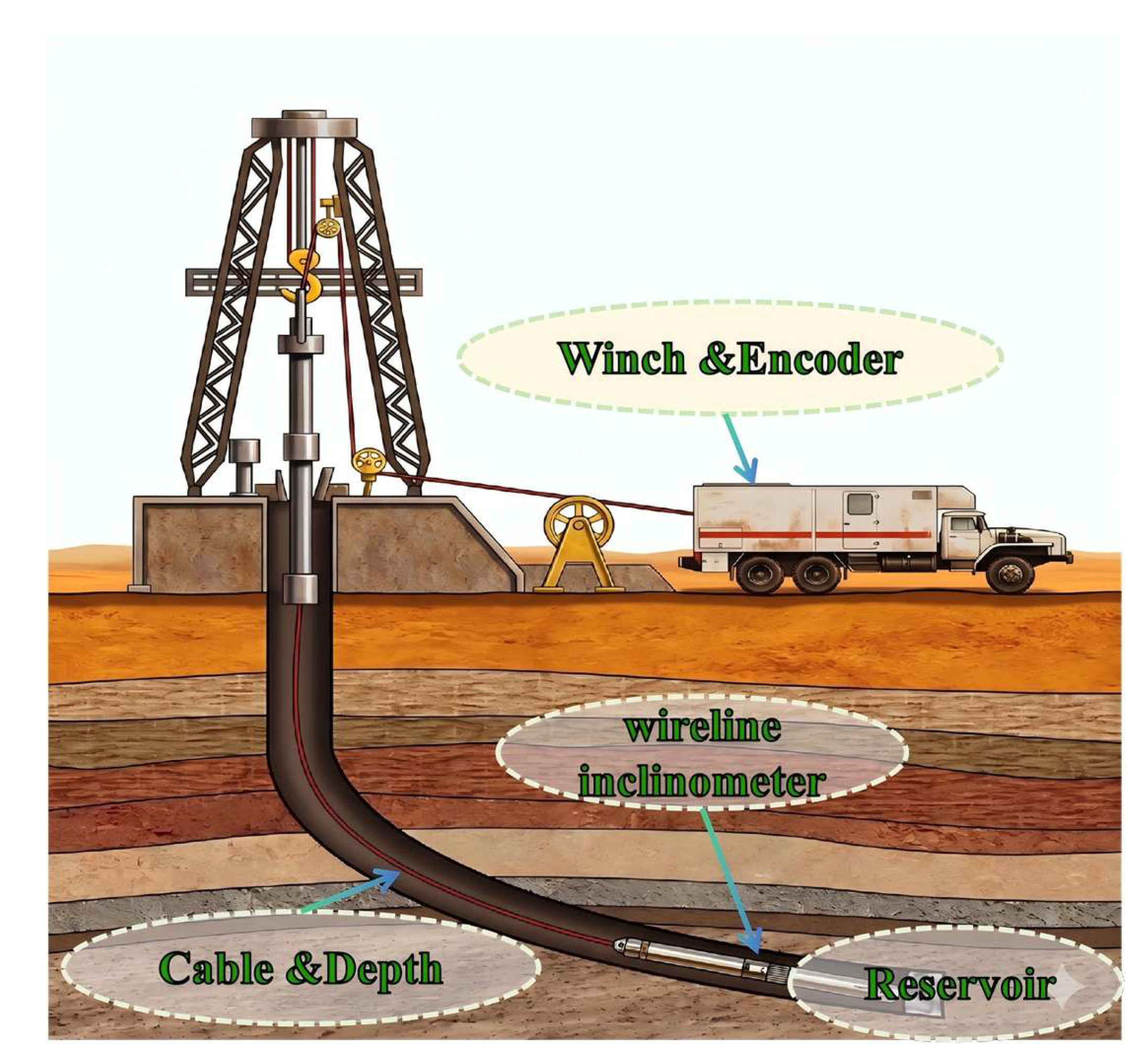
Figure 2.
Operating scenario of the wireless MWD sub.
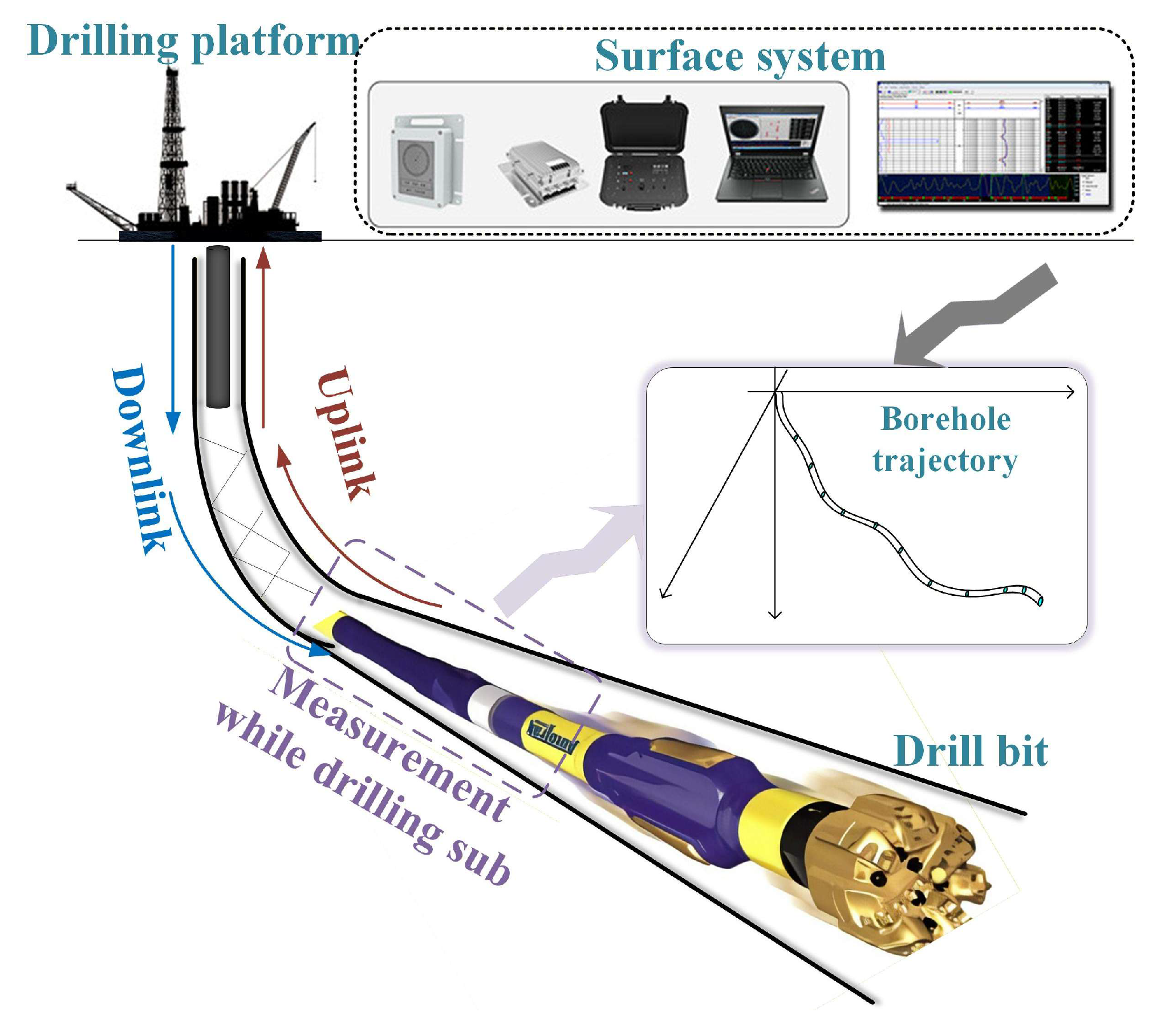
Figure 3.
The definition of wellbore attitude.
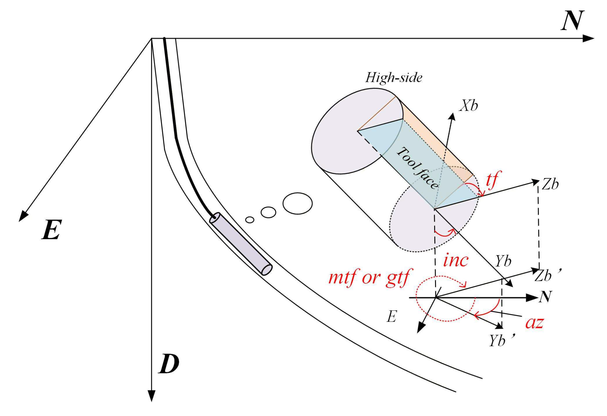
Figure 4.
Comparison of triaxial magnetometer before and after compensation based on EF method. (a) patial distribution of triaxial magnetometer data with errors. (b) Spatial distribution of triaxial magnetometer data calibrated via ellipsoid fitting.
Figure 4.
Comparison of triaxial magnetometer before and after compensation based on EF method. (a) patial distribution of triaxial magnetometer data with errors. (b) Spatial distribution of triaxial magnetometer data calibrated via ellipsoid fitting.
| (a) | (b) |
Figure 5.
Azimuth Measurement Accuracy of a Single-Axis Gyroscope in the 30°~ 0° Inclination Range.
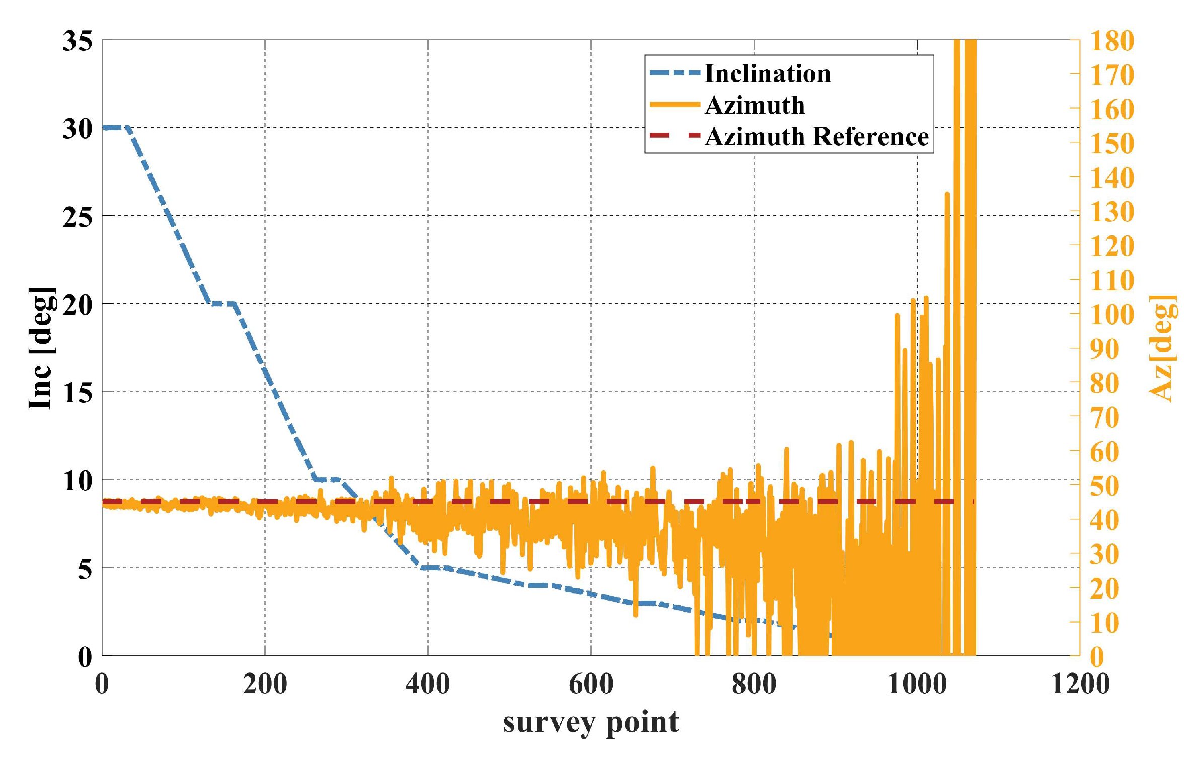
Figure 6.
Azimuth accuracy analysis of a dual-axis gyroscope in the 30°~ 0° inclination range. (a) Azimuth error amplitude characteristics as the inclination angle approaches . (b)Azimuth error amplitude characteristics as the inclination angle approaches .
Figure 6.
Azimuth accuracy analysis of a dual-axis gyroscope in the 30°~ 0° inclination range. (a) Azimuth error amplitude characteristics as the inclination angle approaches . (b)Azimuth error amplitude characteristics as the inclination angle approaches .
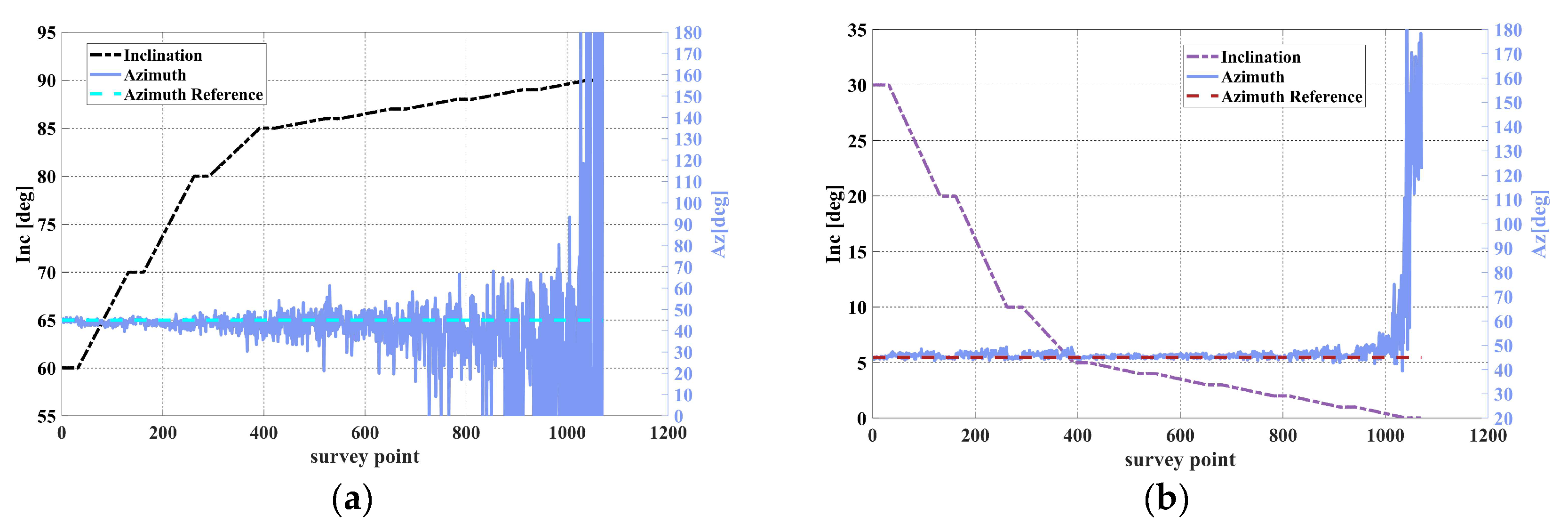
Figure 7.
Impact of accelerometer bias on attitude accuracy in the 30°~0° inclination Range. (a) Error variation curve of gravity toolface angle as inclination approaches 0°.(b) Error variation curve of azimuth angle as inclination approaches 0°.
Figure 7.
Impact of accelerometer bias on attitude accuracy in the 30°~0° inclination Range. (a) Error variation curve of gravity toolface angle as inclination approaches 0°.(b) Error variation curve of azimuth angle as inclination approaches 0°.
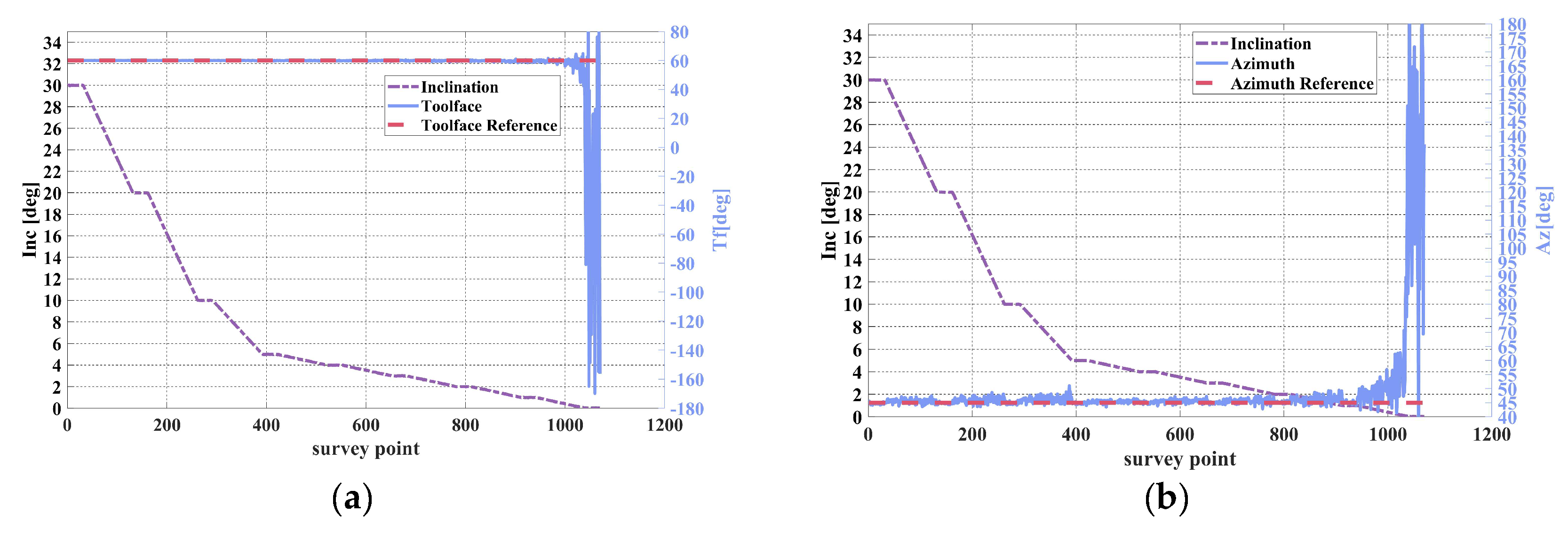
| (a) | (b) |
| (a) | (b) |
Figure 8.
Azimuth Accuracy in the 30°~0° Inclination Range under Low Accelerometer Error Conditions.
Figure 8.
Azimuth Accuracy in the 30°~0° Inclination Range under Low Accelerometer Error Conditions.
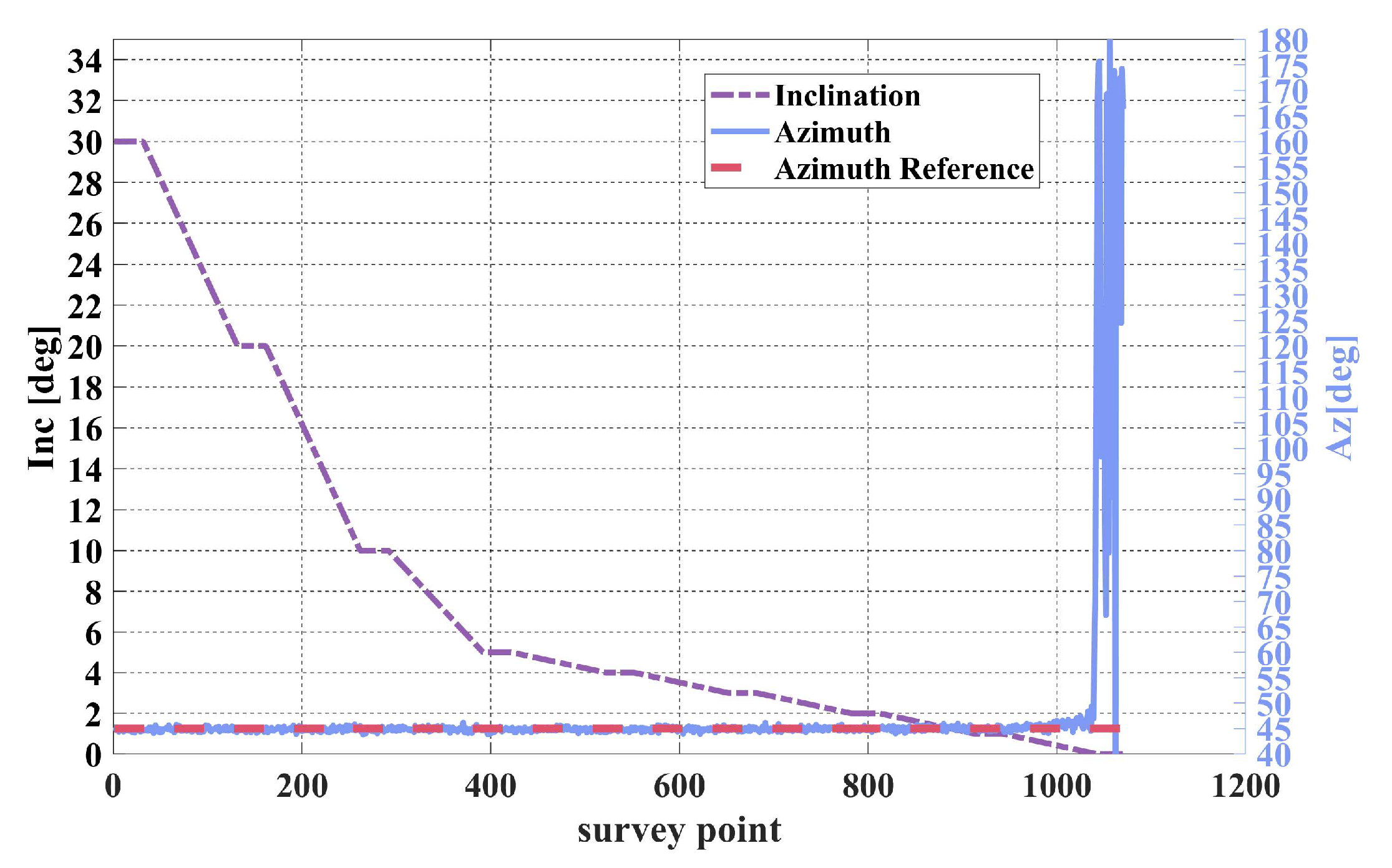
Figure 9.
Schematic diagram of the wellbore trajectory reconstruction method.
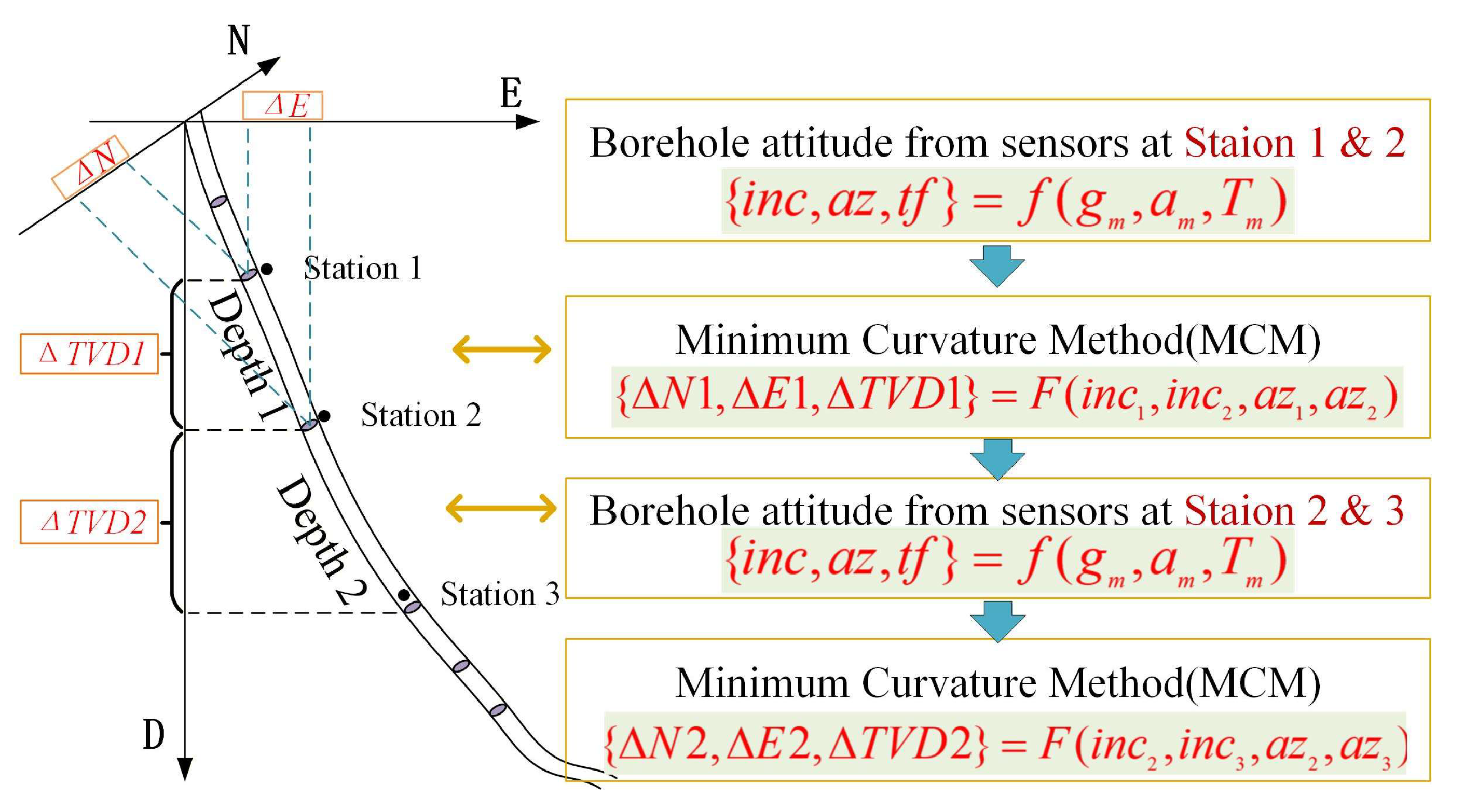
Figure 10.
Schematic Diagram of the Spatial Geometry Assumption of the MCM.
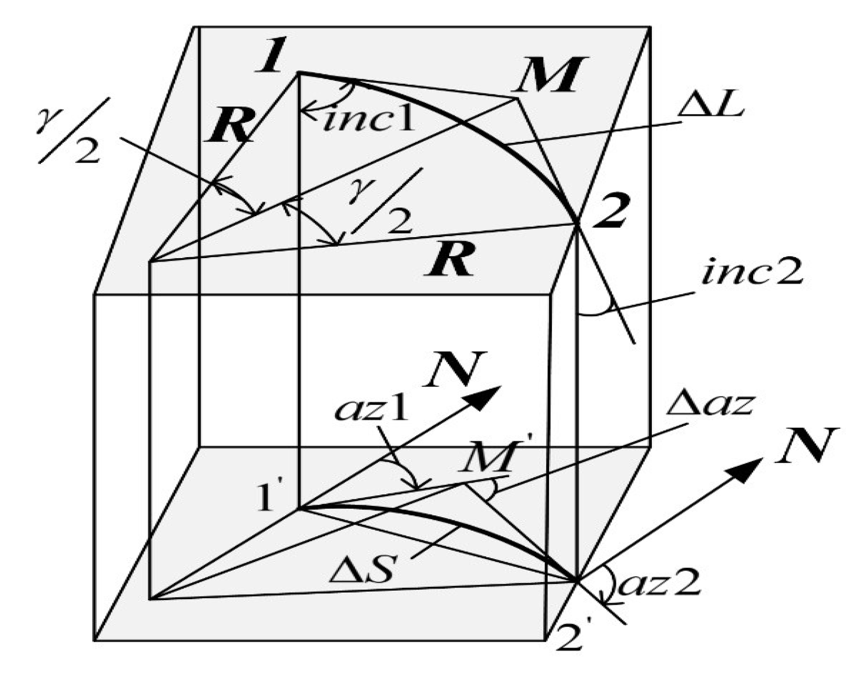
Figure 11.
SINS trajectory component cumulative error over 1 hour. (a) Attitude error curves over 1 hour of static navigation; (b) Eastward and northward displacement error curves over 1 hour of static navigation.
Figure 11.
SINS trajectory component cumulative error over 1 hour. (a) Attitude error curves over 1 hour of static navigation; (b) Eastward and northward displacement error curves over 1 hour of static navigation.
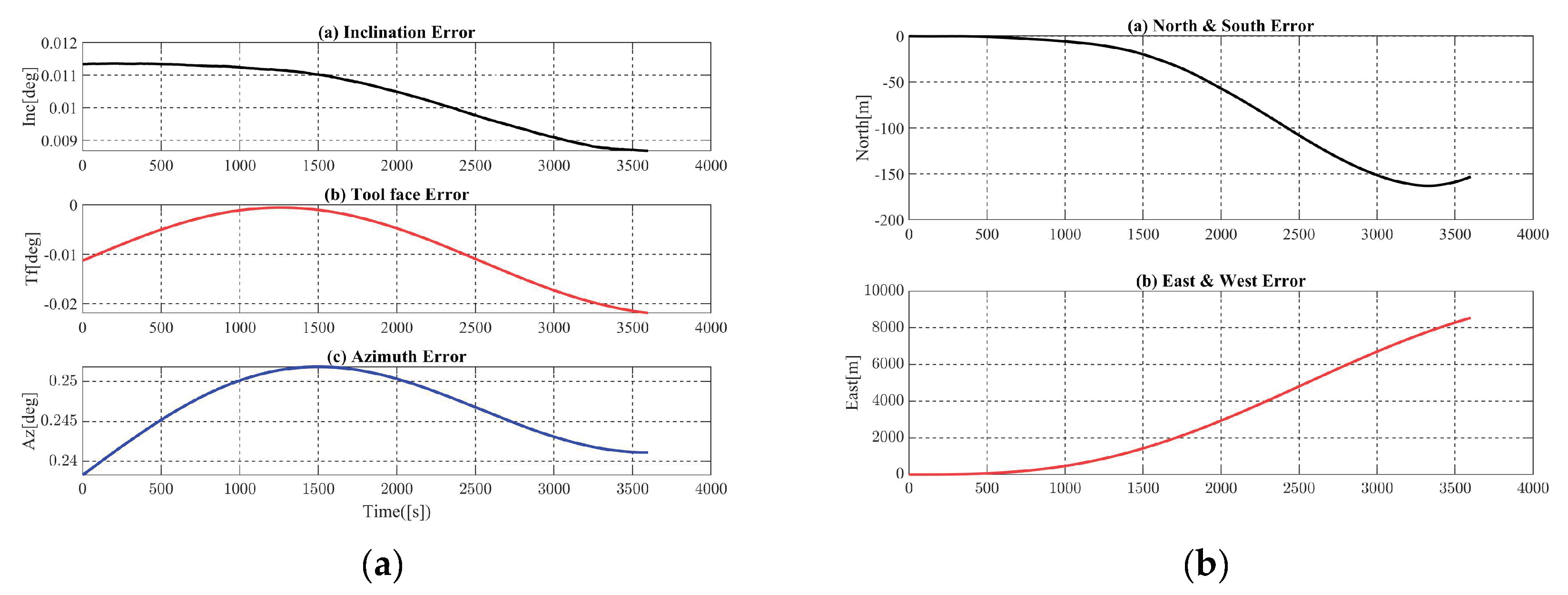
| (a) | (b) |

Table 1.
Typical Sensor Configuration and Attitude Accuracy.
| Company /Institution |
Tool Type | Wellbore attitude accuracy | ||
|---|---|---|---|---|
| Azimuth | Inclination | Tool face | ||
| Schlumberger | Solid-state Gyro(GyroLink) MEMS Gyro (Gyrosphere) |
±0.1° | ±0.05° | ±0.1° |
| Baker Hughes | Magnetometer (MWD) [8] | ±1° | ±0.1° | ±1° |
| Halliburton | BaseStar(MWD) | ±1° | ±0.1° | ±1° |
| GyroStar | / | / | / | |
| Scientific Drilling | Keeper MWD; URSA MWD Solid-state Gyro |
±0.1° | ±0.1° (0°~80°) | ±0.1° |
| Magnetometer (Falcon X) | ±0.25° | ±0.15° | ±0.15° | |
| Weatherford | TrendLine Gyro-while-drilling | ±1° | ±0.1° | ±1° |
| Beihang University | FOG (FMWD,FIW) | ±1° | ±0.1° | ±0.1° |
Table 2.
Applicability of different types of gyroscopes in oil and gas well engineering.
| Parameter | Mechanical Gyro | MEMS Gyro | Ring Laser Gyro | Fiber Optic Gyro |
|---|---|---|---|---|
| Accuracy (°/h) |
Strategic Grade(>0.001) Navigation Grade(0.001~0.05) |
Tactical Grade(0.1~5) Consumer Grade(>5) |
Strategic Grade(>0.001) Navigation Grade(0.001~0.05) |
Strategic Grade(>0.001) Navigation Grade(0.001~0.05) Tactical Grade(0.1~5) |
| Size adaptability | Conventional wellbore. Incapable of near-bit installation. |
Slim hole or conventional wellbore. Capable of near-bit installation. |
Not applicable for wellbore attitude measurement | Slim hole or conventional wellbore; Capable of near-bit installation with flexible design |
| Working temperature | Warm-up required before operation. Typically up to 100 °C. Fluid-floated gyro (e.g., SDI GyroMWD) can reach 150 °C. |
Maximum operating temperature: 150 °C. Significant temperature drift. |
Not capable of downhole operation. Maximum temperature: 70 °C |
Fast start-up. Maximum operating temperature 85 °C. Applicable for vertical build-up section or wells within 2,000m. reach 175 °C with a thermal flask. |
| Vibration shock |
Some mechanical rotor gyros are relatively sensitive to vibration | It has good vibration resistance but a high noise level. | Poor vibration resistance makes it unsuitable for drilling environment. | Fully solid-state packaging. Excellent vibration resistance. |
| power consumption | Precision rotor gyros can reach tens of watts. Certain models can meet downhole operation requirements(e.g., Keeper Gyro) |
As low as mW level, with total system under 2W. | Power consumption is tens of watts or more, which does not meet downhole power requirements. | The total power consumption of the three-axis gyro does not exceed 10W, meeting downhole power requirements. |
Table 3.
Research Framework for Gyro-Based Wellbore Attitude Determination.
| Research Object | Research Aim | Expected Effect |
|---|---|---|
| Inertial sensor | Error characterization; Inertial sensor denoising. |
Reduce the amplitude of gyroscope/accelerometer noise, ensuring stability of attitude angle measurement |
| Working environment | Construct a physical model for error compensation under drilling conditions, enabling highly reliable measurement under dynamic working conditions | High-precision measurement of wellbore attitude angle during continuous drilling or in dynamic environments |
| Measurement scheme | Auxiliary information constraints, compensate for framework errors in the solution | Improve system-level solution performance and wellbore attitude accuracy |
Table 4.
Simulation Settings for Inertial Sensor Error Parameters.
| Sensors | Bias | Random noise |
|---|---|---|
| Gyroscope | 0.05°/h | 0.05°/h(1σ) |
| Accelerometer | 100 μg | 100 μg(1σ) |
Disclaimer/Publisher’s Note: The statements, opinions and data contained in all publications are solely those of the individual author(s) and contributor(s) and not of MDPI and/or the editor(s). MDPI and/or the editor(s) disclaim responsibility for any injury to people or property resulting from any ideas, methods, instructions or products referred to in the content. |
© 2026 by the authors. Licensee MDPI, Basel, Switzerland. This article is an open access article distributed under the terms and conditions of the Creative Commons Attribution (CC BY) license (http://creativecommons.org/licenses/by/4.0/).
Copyright: This open access article is published under a Creative Commons CC BY 4.0 license, which permit the free download, distribution, and reuse, provided that the author and preprint are cited in any reuse.