

Submitted:
06 August 2026
Posted:
07 August 2026
You are already at the latest version
Abstract
This paper presents a Model Predictive Control (MPC)-based energy management strategy for hybrid power systems combining a proton-exchange membrane fuel cell (PEMFC) with a lithium iron phosphate (LFP) battery storage unit for renewable energy applications. The proposed framework optimizes power allocation between the two sources while respecting operational constraints, including current limits, power balance requirements, and state-of-charge (SOC) bounds with soft constraints to prevent overcharging and deep discharging. Unlike conventional rule-based approaches, the MPC formulation employs a quadratic cost function with tunable weighting factors that enable flexible prioritization of either fuel cell conservation or battery lifetime extension. Accurate yet computationally efficient models are developed for both components: an equivalent circuit model for the LFP battery and a theoretical electrochemical model for the PEMFC. The performance of the proposed strategy is validated through comprehensive simulations under realistic renewable generation and load profiles. Five case studies are examined, each representing different operational scenarios characterized by varying initial SOC conditions and component prioritization weights. The results demonstrate that the MPC-based approach effectively manages power distribution, maintains SOC within safe operating ranges, and adapts to changing system conditions. Quantitative analysis shows that the tunable weighting strategy successfully limits high-current events, reducing stress on the battery and extending its operational lifetime. The proposed framework offers a scalable and flexible solution for improving the reliability and economic viability of hybrid energy storage in modern renewable grids.
Keywords:
model predictive control
; energy management system
; hybrid energy storage system
; proton exchange fuel cell
; lithium iron phosphate battery
; hybrid configurations
1. Introduction
The increasing penetration of renewable energy sources (RES) into modern power grids has introduced significant challenges related to intermittency, variability, and grid stability [1]. Solar photovoltaic (PV) and wind power generation are inherently dependent on weather conditions, leading to unpredictable fluctuations that complicate the balance between energy supply and demand. Energy storage systems (ESS) have emerged as a critical enabling technology to address these challenges, providing the necessary flexibility to smooth power fluctuations, shift energy temporally, and enhance overall system reliability [2]. Among the various storage technologies available, fuel cells and battery systems have attracted particular attention due to their complementary characteristics in terms of energy density, power density, and response times [3]. This challenge of integrating variable renewables is not unique to the power sector; other industries, such as water management [4,5,6] and industrial processing [7,8,9], are also exploring hybrid energy solutions to improve operational flexibility and efficiency
Proton-exchange membrane fuel cells (PEMFC) offer high energy density and extended discharge durations, making them suitable for primary power generation in remote or off-grid renewable applications [10]. However, PEMFC systems suffer from relatively slow dynamic response, limited cold-start capabilities, and degradation phenomena associated with load transients and frequent start-stop cycles [11]. Conversely, battery energy storage systems (BESS) provide fast response times, high round-trip efficiency, and excellent power density, effectively compensating for the shortcomings of fuel cells during transient events [12]. Despite these advantages, conventional single-chemistry battery systems exhibit uniform degradation profiles and face limitations in simultaneously satisfying both high-power and high-energy requirements, often leading to accelerated aging and reduced operational lifespan [13].
Recent advances in battery technology have enabled the integration of multiple battery chemistries within a single hybrid storage system, exploiting the distinct characteristics of each chemistry to optimize overall performance [14]. Lithium Iron Phosphate batteries, for instance, offer exceptional thermal stability, long cycle life, and high safety margins, making them particularly attractive for stationary energy storage applications [15]. When combined with other battery chemistries or fuel cell systems, hybrid configurations can effectively partition energy and power demands, thereby mitigating degradation and enhancing system efficiency [16]. Nevertheless, the integration of such hybrid systems introduces substantial complexities in energy management and control, necessitating sophisticated strategies that consider the unique operational constraints, efficiency characteristics, and degradation behaviors of each component [17].
Existing literature has explored various control approaches for hybrid fuel cell/battery systems, ranging from classical rule-based strategies to more advanced optimization techniques [18]. Rule-based controllers, despite their simplicity and ease of implementation, often lack the adaptability required for optimal performance under diverse operating conditions [19]. Model predictive control (MPC) and dynamic programming have demonstrated superior performance in managing energy flows and minimizing operational costs, yet their computational demands and reliance on accurate system models limit their practical applicability [20]. More recently, fuzzy logic controllers and neural network-based approaches have been investigated, offering improved robustness and adaptability. However, the majority of these studies focus primarily on fuel cell degradation mitigation or battery state-of-charge (SOC) regulation in isolation, without comprehensively addressing the synergistic control of battery systems alongside fuel cell units [21].
The primary challenge in hybrid fuel cell/battery systems lies in the coordinated management of distinct storage technologies with disparate dynamic characteristics, degradation mechanisms, and operational constraints [22]. Unlike conventional single-chemistry configurations, battery systems require the simultaneous regulation of multiple SOC levels, power distribution among battery packs, and seamless coordination with the fuel cell's operational schedule [23]. The optimal power split must balance instantaneous power demands, fuel cell efficiency, battery degradation rates, and overall system energy efficiency, while maintaining the SOC of each battery chemistry within safe operational bounds to prevent premature aging [24]. Furthermore, the control strategy must account for the varying response times of each component, ensuring that the fast-acting batteries compensate for the slower dynamics of the fuel cell during transient events [25].
While existing studies have explored MPC for hybrid fuel cell/battery systems, they predominantly rely on simplified component models or single-objective formulations that do not adequately capture the trade-offs between fuel cell efficiency, battery degradation, and system responsiveness. This work advances the state-of-the-art by developing a unified MPC framework that incorporates experimentally validated component models and tunable weighting factors, enabling flexible operational strategies that can be adapted to varying system priorities and operating conditions.
To address these challenges, this paper proposes a Model Predictive Control [26] based energy management framework for hybrid power systems integrating a PEMFC with an LFP battery storage unit. Unlike conventional rule-based strategies that rely on fixed thresholds and heuristic logic, the MPC formulation employs a quadratic cost function that simultaneously minimizes the current drawn from both the LFP battery and the fuel cell, thereby reducing stress on each component and extending their operational lifetimes. By incorporating adjustable weighting factors, the control strategy can dynamically prioritize the use of one system over the other depending on operational requirements and system states. Furthermore, the MPC framework integrates critical operational constraints, including current limits, power balance requirements, and SOC bounds with soft constraints to prevent battery overcharging and deep discharging, ensuring safe and reliable system operation.
The main contributions of this work are threefold. First, we develop accurate yet computationally efficient models for both the LFP battery and the PEMFC, employing an equivalent circuit model (ECM) for the battery and a mathematical/theoretical model based on electrochemical principles for the fuel cell. These models capture the essential nonlinear characteristics of each component while maintaining compatibility with the MPC optimization framework. Second, we formulate a comprehensive MPC-based energy management strategy that optimizes power allocation in a receding horizon fashion, considering future load demands and generation profiles to achieve near-optimal performance. The proposed approach incorporates tunable weights that allow the system operator to prioritize either fuel cell conservation, battery lifetime extension, or a balanced trade-off depending on the specific application and operational context. Third, we validate the proposed control framework through extensive simulations under realistic renewable generation and load profiles obtained from the CREST Demand Model and real wind turbine data. The performance is evaluated across five distinct case studies, each representing different operational scenarios characterized by varying initial SOC conditions and component prioritization weights. The results demonstrate that the proposed MPC-based approach effectively manages power distribution, maintains SOC within safe operating ranges, and adapts to changing system conditions, thereby enhancing overall system reliability and economic viability for remote renewable energy applications.
The paper is organized as follows: Section 2 presents the mathematical models developed for the battery and fuel cell, detailing the ECM approach for the LFP and the theoretical formulation for the PEMFC. Section 3 describes the MPC-based energy management system, including the objective function, constraints, and implementation details. Section 4 presents the case studies, simulation results, and comparative analysis. Section 5 provides a short discussion of the simulation results. Finally, Section 6 concludes the paper with a summary of findings and directions for future research.
2. Mathematical Models
For the best performance of the simulation, the models for the batteries, LFP, and the Fuel Cell need to be accurate and work adequately between them. There are very different types of models for all the batteries and the ones for this system need to fit easily with the energy management system (EMS). Considering the previous characteristics, the models have to not present a high complexity while maintaining precision compared with real-life results.
The type of model chosen for the LFP is an equivalent circuit model while for the Fuel Cell the model chosen is mathematical/theorical model.
3.1. Li-ion Battery Model
The best option for the implementation of this system regarding the Li-ion battery is an equivalent circuit model, also known as EMS. This model represents the functioning of the battery expressed as an electrical circuit model. This circuit, based on the Thevenin ECM, is composed of an ideal voltage source, representing the open circuit voltage (OCV), a resistance, representing the ohmic losses from the battery as seen in Figure 1:
The values regarding the OCV, resistance and RC from the ECM are obtained from real-life characterization experiments, based on discharging and charging the battery with a series of pulses with low current at discrete SOC values, from Basytech, a battery cycler, for the battery that is replicated. The values are directly linked with the value of the SOC, as the OCV and the resistances and capacitances have a significant variance in the low and high values of the SOC.
The Li-ion battery chosen is a Lithium Phosphate Iron characterized by a nominal voltage of 3.2V and a capacity of 280Ah.
The model is created in MATLAB code. The model is represented in the code by a state space, a mathematical model that represents the responses of the physical model. For the battery model there is 1 state variable, which is the SOC and 1 input variable, the current. The values obtained from the experimental data are used to provide polynomial functions using the SOC as a variable.
The state equation is described as:
where
X = A·X + B·U,
- X are the state variables (SOC, V1, V2, V3).
- U is the input variable (current).
- A is the state matrix.
- B is the input matrix.
The state and input matrices are defined as:
The equation for the input matrix is characterized as:
where:
- ε is the value of the slight loss of capacity in each cycle completed. It has different values for charging and discharging.
- ∆t is the time step.
- Qn is the cell capacity.
With the depiction of the battery system, the voltage is calculated as the following equation:
3.2. Fuel Cell Model
For the Fuel Cell model, the more suited model for the system and especially the energy management system is a mathematical/theorical model which calculates the voltage using the basic electrochemical principles and mathematical equations regarding different variables (current and temperature).
There are different types of Fuel Cells but for our system the Proton Exchange Membrane (PEM) has been chosen. PEM fuel cells have been highly known for commercial uses, making them highly reliable and studied.
In this kind of Fuel cells, only hydrogen and oxygen are used as the principal reaction to obtain electricity and water. The reactions happening in the anode and cathode are the following ones:
The ideal voltage is calculated from these reactions, obtaining a value similar to 1.21V. However, there are different types of losses from the functioning of the Fuel Cell that lowers this voltage. These losses are the activation losses, the ohmic losses and the concentration losses which are calculated in the following equation 4, equation 5, equation 6 and equation 7, [27].
3.2.1. Activation Voltage
The slow speed of the electrochemical reactions at the electrode surface is the cause of the activation losses. It is directly proportional to the increase of flow, which makes them higher when a low current is used. One of the ways to calculate this voltage is using the following equation:
where:
- R is the gas constant, J٠mol-1٠K-1
- T is the temperature, K
- F is the Faraday constant, C٠mol-1
- c is the number of cells in the battery
- n is the numbers of electrons involved in the reactions, which in the PEM fuel cells are 2,
- α is the charge transfer coefficient,
- i is the current or the current density, A or A٠m-2
- io is the exchange current or current density, A or A٠m-2
3.2.2. Ohmic Voltage
The resistance to the flow of ions in the electrolyte and the resistance of electrons in the electrodes and the external electrical circuit are the cause of the ohmic losses. In this case, this type of losses increases with a higher current value. The best way to calculate it is using the following equation:
where:
- i is the current, A
- RC is the resistance of the fuel cell, Ω
3.2.3. Concentration Voltage
The drop in the initial concentration of the bulk of the fluid in the surroundings when the reactant gas is consumed in the electrode creating a concentration gradient polarization is the cause of concentration losses. This voltage can be calculated as:
where:
- R is the gas constant, J٠mol-1٠K-1
- T is the temperature, K
- F is the Faraday constant, C٠mol-1
- c is the number of cells in the battery
- n is the numbers of electrons involved in the reactions, which is still the same value as with the activation losses
- i is the current or the current density, A or A٠m-2
- il is the limiting current or current density, A or A٠m-2
Combining the value of the ideal or standard voltage with the different losses gives the real-life voltage of the cell, expressed as:
All these equations for the model have been developed in MATLAB code.
3. Energy Management System: MPC
The energy management system is a requirement for all types of combinations between all the energy storage and generation systems. The use of the different systems comes with a clear understanding of the different characteristics the systems can provide. Searching for the best outcome for different cases and energy demands makes optimization control strategies seem to be the best option and from this type of strategies, Model Predictive Control has been selected for the implementation of this system.
Model Predictive Control, also known as MPC, is a type of optimization control strategy that optimizes the system from the minimization of an objective function. The most remarkable idea for this control strategy is the use of a number of steps in the future, known as control horizon (Nc), where the control trajectory is predicted for each step. This work provides a better-informed result for the objective function in each step as it gives a value calculated with the future outcome in mind. Another attribute this strategy gives is the implementation of different constraints for the different variables considered, expanding the level of control that can be implemented in the system.
3.1. Objective Function
For this system, the objective function is defined as a Quadratic cost function that considers the current for both the LFP and the Fuel Cell variables that need to be minimized. Each variable is accompanied by a weight, which determines the importance of each variable during the optimization as a higher value of this weight forces the control to have a lesser use of that system.
The objective function is defined as:
3.2. Constraints
As said previously, different constraints are considered as a way to provide the best way to emulate the restrictions the real-life system has.
The first one establishes that the power from the LFP and FC have to provide the power demand. It is defined as:
The second one establishes that the current of the LFP and FC have to be between its highest and lowest value from real life. It is defined as:
The last one establishes that the State of Charge of the LFP has to be between its highest and lowest value from real life. In this system, the range of the LFP SOC is between 0.1 and 0.9 to avoid overcharging and overdischarging. For this constraint, as the limits are not the same as the real-life ones, can be not respected with the slack variable. It is defined as:
where
- ε is the slack variable.
This slack variable must be part of the cost function and needs to have its importance detailed with a weight value. It is defined as:
Combining Qsoft with the previously expressed objective function, the Quadratic problem solved for each step k is defined as:
Subjected to the different constraints expressed previously.
4. Cases of Study and Results
This model presents its use with the combination of the LFP and FC with a renewable energy system composed of a photovoltaic plant and a wind turbine in a stationary and isolated use.
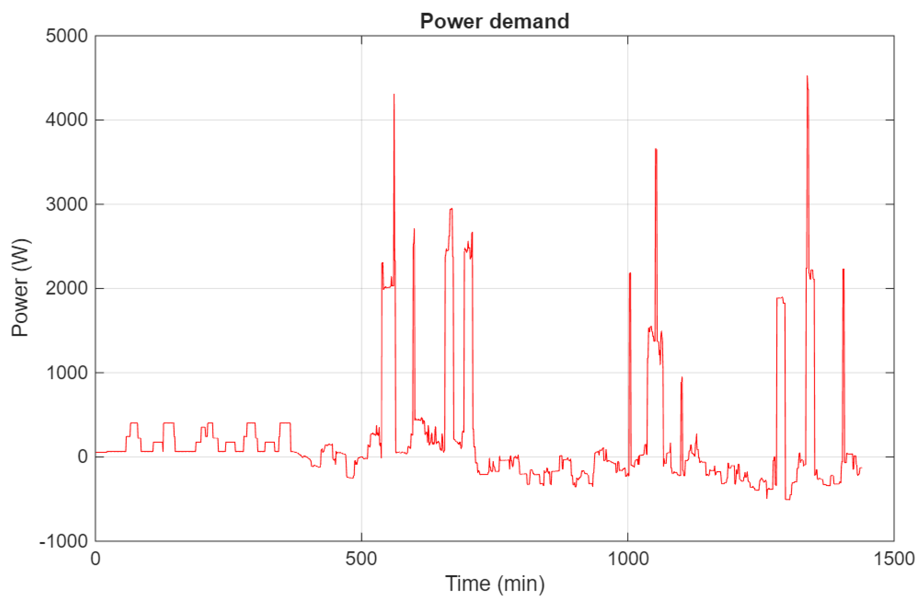
The power demand and PV generation has been obtained from the CREST Demand Model, using one household to represent the demand for the microgrid while the Wind energy generation has been calculated using the theorical power from the datasheet of a real-life wind turbine. The power demand considered for the system is the power demand presented by the CREST Demand Model minus the photovoltaic and wind power. The power demand shown corresponds to the power demand for a day while each step corresponds to 1 min. The power demand ends up being like this:
Figure 2.
Power demand for the system.
Considering the scale of the power needed, the LFP and the FC are used as modules formed from different cells in series, incrementing the total voltage and power. The LFP module is composed of 5 cells, making it a nominal voltage of 16V; and the FC module is composed of 45 cells, making it a nominal voltage of 45 V. The maximum voltage the LFP module can tolerate is 140 A while the maximum voltage for the FC module is 200 A.
To evaluate the MPC and examine its behavior, the model is tested in different cases of study with different weights for the current for the LFP and FC and SOC value for the LFP.
The first case, case A, is considered without any importance for one of the systems while the LFP has a high SOC value. The second one, case B, has the same consideration of not having any importance for one of the systems but the LFP has a low SOC value. The third case, case C, considers the FC to be more restricted on its use while the final case, case D, considers the LFP to be more restricted on its use. In these last two cases, the SOC value for the LFP is medium-high. Finally, the last case, presents the system without control, with still a medium-high SOC value.
In all the cases, it is considered to not have a reason to need a more permissive constraint with the LFP SOC, giving a high value to the weight for the slack variable, with a value of 5·108.
In Table 1, there is the values of the weights for both LFP and FC currents and the initial SOC value for the LFP.
4.1. Case A
This case offers the best scenario for the system, as there is no restriction for the LFP and FC in their use. The idea is to have complete availability of the elements for the MPC to decide the power given by each one. LFP’s SOC initial value is 70% which puts it at a medium-high range of value.
The power delivered by the LFP and FC is shown in Figure 3:
While the SOC value for the LFP is shown in Figure 4:
The results show the LFP and FC being used in a similar fashion with a clear difference as the FC is used for the highest peaks of demand while the LFP is the only one that can get the excess of energy from the PV and wind turbine generation.
4.2. Case B
This case offers a very favorable scenario for the system; there is still no restriction from the control strategy for the LFP and FC but the initial SOC value for the LFP is in a low range, with an initial value of 30%, theoretically limiting the operation of the LFP.
The power delivered by the LFP and FC is shown in Figure 5:
While the SOC value for the LFP is shown in Figure 6:
The results show the FC providing the majority of the power for the power demand and even being used to charge the LFP battery. The LFP only gives power in the highest peaks of the power demand and it is especially used to absorb the excess of power to be charged.
4.3. Case C
This case offers the first direct restriction from the MPC. In this case, the idea is to protect the FC increasing the value of the weight associated with the FC’s current and only be used when it is strictly needed to achieve the power demand. The LFP’s SOC is on the medium-high range, with an initial value of 70%, for the element to have an adequate supply of the power.
The power delivered by the LFP and FC is shown in Figure 7:
While the SOC value for the LFP is shown in Figure 8:
As expected, the LFP provides the majority of the power needed. The FC only appears with the higher peaks and in the last parts of the simulation when the LFP gets near discharge and not only takes advantage from the excess of power but also uses a part of the FC power to get charged.
4.4. Case D
This case is characterized by the restriction of the LFP battery with the MPC. Similar to the previous case but changing the element being restricted with the LFP being protected in its use with a high weight value for its current with the idea of only being used when it is strictly needed. The LFP’s SOC is still in the medium-high value, with an initial value of 70%.
The power delivered by the LFP and FC is shown in Figure 9:
While the SOC value for the LFP is shown in Figure 10:
As expected, the FC provides the majority of the power needed. The LFP only works taking in the excess of energy as the FC cannot do it. The only moment the LFP gives energy is when it is completely charged.
4.5. Case E
This last case is characterized by the not use of the control system, considering the system to provide each element half of the power demand regardless of the characteristics of each element. The SOC initial value for the LFP is the same as the previous case, 70%.
The power delivered by the LFP and FC is shown in Figure 11:
While the SOC value for the LFP is shown in Figure 12:
5. Discussion
The simulation results demonstrate that the proposed hybrid system, combining an LFP battery with a PEMFC, effectively meets the power demand throughout all operational scenarios. In every case examined, the combined power output from the battery and fuel cell, together with the renewable generation from the PV plant and wind turbine, successfully satisfies the required load profile. This confirms that the system architecture is appropriately sized and that the coordination between the two energy sources is functionally adequate for the considered application.
A key finding of this study is that the hybrid configuration successfully avoids the overutilization of a single component, which is a common limitation in systems relying exclusively on battery storage. In scenarios where the LFP battery alone would be insufficient to sustain the load throughout the entire simulation period, the fuel cell effectively supplements the power supply, preventing premature battery depletion. Conversely, during periods of low demand or excess renewable generation, the battery absorbs surplus energy, maintaining system stability and ensuring that the fuel cell operates within its most efficient range. This complementary behavior validates the rationale behind integrating both technologies and highlights the advantage of the hybrid approach over single-source configurations.
The Model Predictive Control strategy demonstrates remarkable flexibility in adapting to varying operating conditions, as evidenced by the distinct system responses observed across the five case studies. Unlike conventional rule-based controllers that rely on fixed decision thresholds, the MPC framework continuously optimizes the power split based on the current system state and predicted future conditions. This predictive capability proves particularly beneficial for long-duration simulations with fluctuating power demands, where the system must continuously adjust to changing generation and load patterns. The ability of the MPC to anticipate future events and preemptively adjust the power allocation contributes to more efficient and stable system operation compared to reactive control approaches. The comparison between the case without control and the other cases reveals more clearly this flexibility, as both have to deliver exactly the same power which is not always a good option and, in some cases, it cannot be able to sustain it as, for example, the LFP with a lower initial SOC would be unable to deliver the needed power without discharging first.
Notably, the MPC formulation employed in this study considers only two primary variables, the LFP battery's state of charge and the currents of both the LFP and the fuel cell. Despite this relatively limited set of optimization variables, the controller exhibits robust performance across all tested scenarios. The comparison between Case A and Case B is particularly illustrative of the controller's sensitivity to system conditions: with identical weighting factors but different initial SOC values (70% versus 30%), the system behavior diverges substantially. In Case B, the low initial SOC forces the fuel cell to assume the majority of the power supply, while the battery is primarily used for absorbing excess energy and providing support during high-demand peaks. This demonstrates that the MPC effectively responds to the battery's state of charge, automatically adjusting its strategy to prevent deep discharge while maintaining the required power balance.
The weighting factors incorporated into the objective function provide an additional degree of control flexibility, enabling the system operator to prioritize specific components according to operational objectives. In Case C, where the fuel cell current weight is set to 5, the controller successfully limits fuel cell utilization, reserving it for high-demand periods and battery charging when the LFP approaches its lower SOC limit. Similarly, in Case D, the high weight assigned to the battery current effectively protects the LFP from frequent high-current demands, extending its lifespan by reducing stress from high discharge rates. The ability to tune these weights offers a practical mechanism for implementing different operational strategies, such as maximizing fuel cell efficiency, extending battery lifetime, or achieving a balanced trade-off between both objectives. This tunability is particularly valuable for real-world applications where operational priorities may change over time or vary across different installations.
The results also underscore the importance of protecting the battery from high-current events, which are known to accelerate degradation and reduce the state of health (SOH) of LFP cells. By assigning higher weights to the battery current, the MPC can effectively limit the battery's contribution during high-power demand periods, shifting the burden to the fuel cell instead. This strategic load distribution not only preserves battery health but also improves overall system reliability, as the fuel cell is inherently better suited for sustained high-power operation. Conversely, when the fuel cell is assigned a higher weight, the battery assumes a more active role, which may be advantageous in scenarios where hydrogen availability is limited or fuel cell efficiency is suboptimal.
Despite the satisfactory performance of the current MPC formulation, several opportunities for enhancement merit consideration in future work. The incorporation of additional variables into the optimization framework could yield further improvements in system performance and component longevity. For instance, including hydrogen consumption as an explicit optimization objective would enable the controller to directly minimize operational costs and improve overall system efficiency. Similarly, integrating the state of health of the LFP battery into the objective function would allow the MPC to account for aging effects and implement proactive strategies for lifetime extension, such as avoiding operating conditions that accelerate capacity fade. The inclusion of temperature dynamics for both the battery and the fuel cell could also enhance the model's accuracy and enable the controller to prevent thermal stress, which is a significant contributor to degradation in both technologies.
In summary, the proposed MPC-based energy management system provides an effective and flexible framework for controlling hybrid PEMFC/LFP systems in renewable energy applications. The results confirm that the controller successfully coordinates the two energy sources, maintains safe operating conditions, and adapts to changing system states. The tunable weighting factors offer system operators the flexibility to prioritize different operational objectives, making the approach suitable for a wide range of applications and operational scenarios. With further refinements incorporating additional state variables and uncertainty handling, the proposed framework has the potential to significantly enhance the efficiency, reliability, and economic viability of hybrid renewable energy systems.
6. Conclusions
This study has presented a Model Predictive Control-based energy management strategy for hybrid power systems combining a PEM fuel cell and an LFP battery in renewable energy applications. The proposed framework addresses the key challenge of coordinating two distinct energy sources with complementary but different dynamic characteristics, degradation mechanisms, and operational constraints. Through the development of accurate yet computationally efficient models for both components, an equivalent circuit model for the LFP battery and a theoretical electrochemical model for the PEMFC, and their integration within an MPC optimization framework, this work has demonstrated a practical and effective solution for hybrid system control.
The simulation results across five distinct case studies confirm the effectiveness and flexibility of the proposed approach. The hybrid configuration successfully meets the power demand in all scenarios, avoiding the overutilization or premature depletion of either component. The MPC controller demonstrates robust performance by adaptively adjusting power allocation based on system states, as evidenced by the markedly different responses observed when only the initial battery state of charge was varied between Case A and Case B. The incorporation of tunable weighting factors enables flexible prioritization of system components, allowing operators to implement diverse operational strategies ranging from fuel cell conservation to battery lifetime extension, as demonstrated in Cases C and D. Case E presents the functioning of the system without the MPC which reveal the problems a lack of flexibility offer. These results highlight the superiority of the MPC approach over the lack of a control strategy and even conventional rule-based strategies, which lack the adaptability and predictive capability necessary for optimal performance under dynamic operating conditions.
While the current implementation has demonstrated satisfactory performance, several avenues for future research and improvement have been identified. The incorporation of additional optimization variables, such as hydrogen consumption, battery state of health, and temperature dynamics, could further enhance system efficiency and component longevity. The integration of forecasting models for renewable generation and load demand would enable the MPC to handle uncertainty more effectively, facilitating real-world deployment. Furthermore, experimental validation on a physical test bench would confirm the practical feasibility of the proposed approach and address implementation challenges such as communication delays and measurement noise.
Author Contributions
Conceptualization, L.T and P.A.; methodology, L.T., L.G. and J.L.D.-G.; investigation, P.A. and A.C.; writing—review and editing, P.A. and L.G. All authors have read and agreed to the published version of the manuscript.
Funding
This research was funded by the European Union, grant number 101216330. Views and opinions expressed are however those of the author(s) only and do not necessarily reflect those of the European Union or the European Research Executive Agency (REA). Neither the European Union nor the granting authority can be held responsible for them.
Data Availability Statement
Research data is unavailable due to privacy policy.
Conflicts of Interest
The authors declare no conflict of interest.
Abbreviations
The following abbreviations are used in this manuscript:
| BESS | Battery Energy Storage Systems |
| CREST | Centre for Renewable Energy Systems Technology |
| ECM | Equivalent Circuit Model |
| EMS | Energy Management System |
| ESS | Energy Storage Systems |
| FC | Fuel Cell |
| LFP | Lithium Iron Phosphate |
| MPC | Model predictive Control |
| OCV | Open Circuit Voltage |
| PEMFC | Proton Exchange Membrane Fuel Cell |
| PV | Photovoltaic |
| RES | Renewable Energy Sources |
| SOC | State of Charge |
| SOH | State of Health |
References
- Liserre, M.; Sauter, T.; Hung, J.Y. Future energy systems: Integrating renewable energy sources into the smart power grid through industrial electronics. IEEE Ind. Electron. Mag. 2010, 4, 18–37. [Google Scholar] [CrossRef]
- Dunn, B.; Kamath, H.; Tarascon, J.-M. Electrical energy storage for the grid: A battery of choices. Science 2011, 334, 928–935. [Google Scholar] [CrossRef] [PubMed]
- Das, V.; Padmanaban, S.; Venkitusamy, K.; Selvamuthukumaran, R.; Blaabjerg, F.; Siano, P. Recent advances and challenges of fuel cell based power systems. Renew. Sustain. Energy Rev. 2017, 80, 23–46. [Google Scholar]
- Gevorkov, L.; Šmídl, V.; Sirový, M. Model of Hybrid Speed and Throttle Control for Centrifugal Pump System Enhancement. In Proceedings of the 2019 IEEE 28th International Symposium on Industrial Electronics (ISIE), Vancouver, BC, Canada, 12–14 June 2019; pp. 563–568. [Google Scholar]
- Bakman, I.; Gevorkov, L. Speed control strategy selection for multi-pump systems. In Proceedings of the 2015 56th International Scientific Conference on Power and Electrical Engineering of Riga Technical University (RTUCON), Riga, Latvia, 14–14 October 2015; pp. 1–4. [Google Scholar]
- Gevorkov, L.; Bakman, I.; Vodovozov, V. Hardware-in-the-loop simulation of motor drives for pumping applications. In Proceedings of the 2014 Electric Power Quality and Supply Reliability Conference (PQ), Rakvere, Estonia, 11–13 June 2014; pp. 203–208. [Google Scholar]
- Auton, J.C.; Deidun, L.; Sturman, D.; Churruca, K.; Morrison, B.W.; Molesworth, B.R.C.; Wiggins, M.W. Adapting to renewable energy: A mixed methods exploration of safety culture and training needs in Australia’s electricity distribution industry. J. Saf. Res. 2026, 97, 197–206. [Google Scholar] [CrossRef] [PubMed]
- Kwakwa, P.A. Carbon dioxide emissions reduction strategies in Kenya: The synergy between renewable energy, technical cooperation grants and the manufacturing industry. Technol. Sustain. 2026, 5, 20–42. [Google Scholar]
- Bellan, S.; Cuzzolin, E.; Tardivo, F.; Meneghetti, A. Matching Industry 5.0 and Renewable Energy Integration: An optimization approach for robotic warehouses. Procedia Comput. Sci. 2026, 277, 81–90. [Google Scholar] [CrossRef]
- Sharaf, O.Z.; Orhan, M.F. An overview of fuel cell technology: Fundamentals and applications. Renew. Sustain. Energy Rev. 2014, 32, 810–853. [Google Scholar] [CrossRef]
- Pei, P.; Chen, H. Main factors affecting the lifetime of proton exchange membrane fuel cells in vehicle applications: A review. Appl. Energy 2014, 125, 60–75. [Google Scholar] [CrossRef]
- Saadaoui, F.; Mammar, K.; Habbab, M. Energy management of a hybrid energy system (PV / PEMFC and lithium-ion battery) based on hydrogen minimization modeled by macroscopic energy representation. Int. J. Hydrogen Energy 2023, 48, 20388–20405. [Google Scholar] [CrossRef]
- Li, J.; Murphy, E.; Winnick, J.; Kohl, P.A. Studies on the cycle life of commercial lithium ion batteries during high rate pulse discharge. J. Power Sources 2001, 102, 302–309. [Google Scholar] [CrossRef]
- Hesse, H.C.; Schimpe, M.; Kucevic, D.; Jossen, A. Lithium-ion battery storage for the grid—A review of stationary battery storage system design tailored for applications in modern power grids. Energies 2017, 10, 2107. [Google Scholar] [CrossRef]
- Padhi, A.K.; Nanjundaswamy, K.S.; Goodenough, J.B. Phospho-olivines as positive-electrode materials for rechargeable lithium batteries. J. Electrochem. Soc. 1997, 144, 1188–1194. [Google Scholar] [CrossRef]
- Xiong, R.; Sun, F.; Chen, Z.; He, H. A data-driven multi-scale extended Kalman filtering based parameter and state estimation approach of lithium-ion polymer battery in electric vehicles. Appl. Energy 2014, 113, 463–476. [Google Scholar] [CrossRef]
- Si, S.; Yang, B.; Gao, B.; Zhang, Z.; Zhao, B.; Zhang, T.; Xu, H. A real-time energy management strategy combining rule and optimization for minimizing energy consumption and emissions of flywheel hybrid electric vehicle (FHEV). Appl. Therm. Eng. 2024, 255, 124013. [Google Scholar] [CrossRef]
- Garcia, P.; Torreglosa, J.P.; Fernandez, L.M.; Jurado, F. Control strategies for high-power electric vehicles powered by hydrogen fuel cell, battery and supercapacitor. Expert Syst. Appl. 2013, 40, 4791–4804. [Google Scholar] [CrossRef]
- Li, C.Y.; Liu, G.P. Optimal fuzzy power control and management of fuel cell/battery hybrid vehicles. J. Power Sources 2009, 192, 525–533. [Google Scholar] [CrossRef]
- Pisu, P.; Rizzoni, G. A comparative study of supervisory control strategies for hybrid electric vehicles. IEEE Trans. Control Syst. Technol. 2007, 15, 506–518. [Google Scholar] [CrossRef]
- Clemente, A.; Arias, P.; Gevorkov, L.; Trilla, L.; Obrador Rey, S.; Roger, X.S.; Domínguez-García, J.L.; Filbà Martínez, À. Optimizing Performance of Hybrid Electrochemical Energy Storage Systems through Effective Control: A Comprehensive Review. Electronics 2024, 13, 1258. [Google Scholar] [CrossRef]
- Zhao, X.; Wang, L.; Zhou, Y.; Pan, B.; Wang, R.; Wang, L.; Yan, X. Energy management strategies for fuel cell hybrid electric vehicles: Classification, comparison, and outlook. Energy Convers. Manag. 2022, 270, 116179. [Google Scholar] [CrossRef]
- Choi, M.E.; Seo, S.W. Energy management optimization in a battery/supercapacitor hybrid energy storage system. IEEE Trans. Smart Grid 2012, 3, 463–472. [Google Scholar] [CrossRef]
- Guo, J.; He, H.; Jia, C.; Guo, S. The Energy Management Strategies for Fuel Cell Electric Vehicles: An Overview and Future Directions. World Electr. Veh. J. 2025, 16, 542. [Google Scholar] [CrossRef]
- Wang, W.; Hao, Z.; Qu, F.; Li, W.; Wu, L.; Li, X.; Wang, P.; Ma, Y. Review of Energy Management Methods for Fuel Cell Vehicles: From the Perspective of Driving Cycle Information. Sensors 2023, 23, 8571. [Google Scholar] [CrossRef] [PubMed]
- Kadir, N.; Brookson, A.; Fung, A.S. Feasibility of Residential Energy Management Systems with Renewable Generation and Battery Storage. Energies 2026, 19, 3055. [Google Scholar] [CrossRef]
- Pilatowsky, I.; Romero, R. J.; Isaza, C. A.; Gamboa, S. A.; Sebastian, P. J.; Rivera, W. Thermodynamics of Fuel Cells. In Cogeneration Fuel Cell-Sorption Air Conditioning Systems; Pilatowsky, I., Romero, R. J., Isaza, C. A., Gamboa, S. A., Sebastian, P. J., Rivera, W., Eds.; Springer, 2011; pp. 25–36. [Google Scholar] [CrossRef]
Figure 1.
Diagram of the equivalent circuit model of the battery based on the Thevenin model.
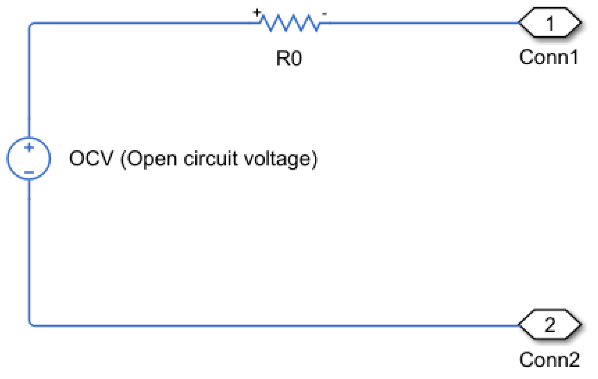
Figure 3.
Power delivered by LFP and FC in case A.
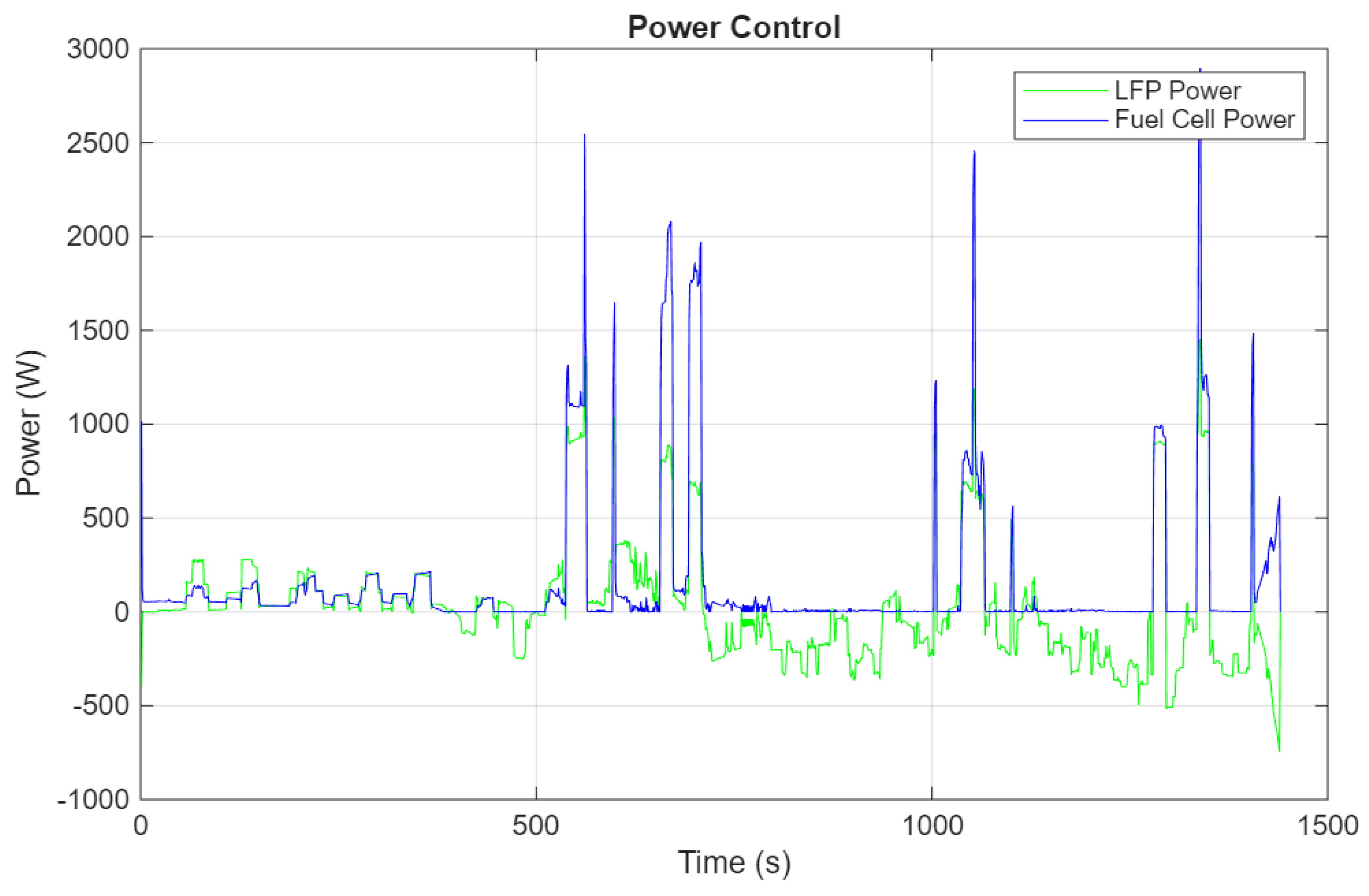
Figure 4.
LFP SOC value in case A.
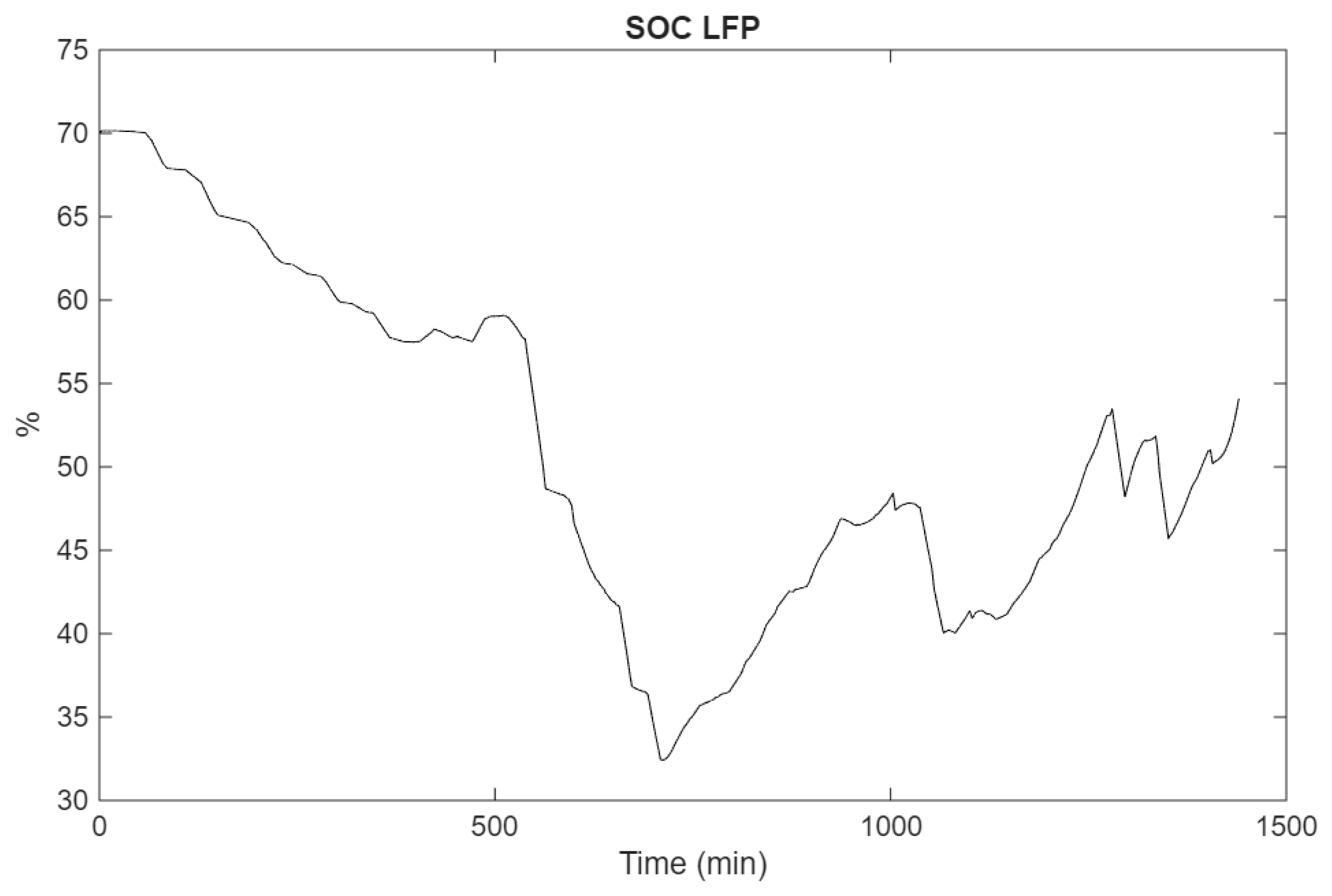
Figure 5.
Power delivered by LFP and FC in case B.
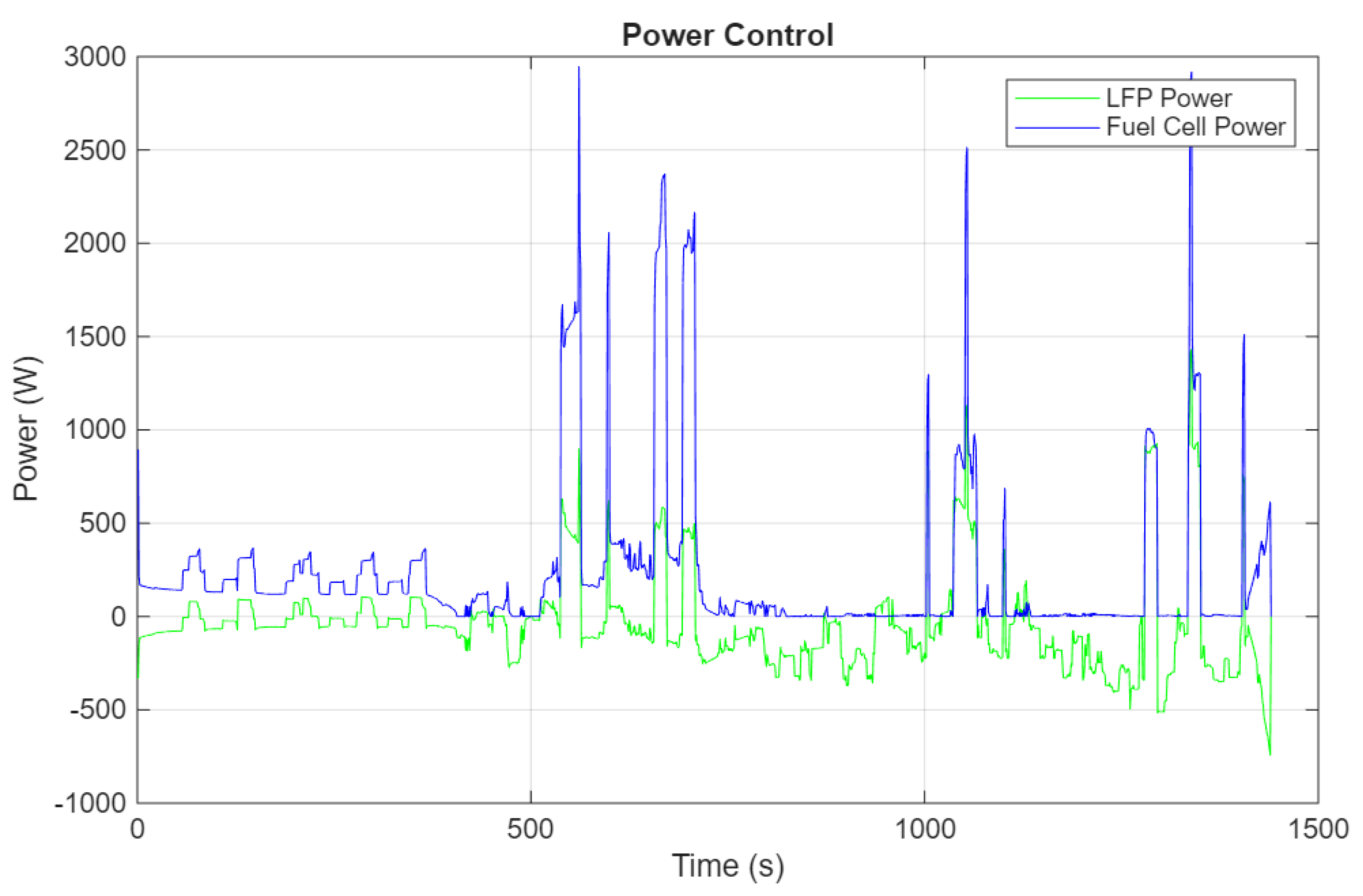
Figure 6.
LFP SOC value in case B.
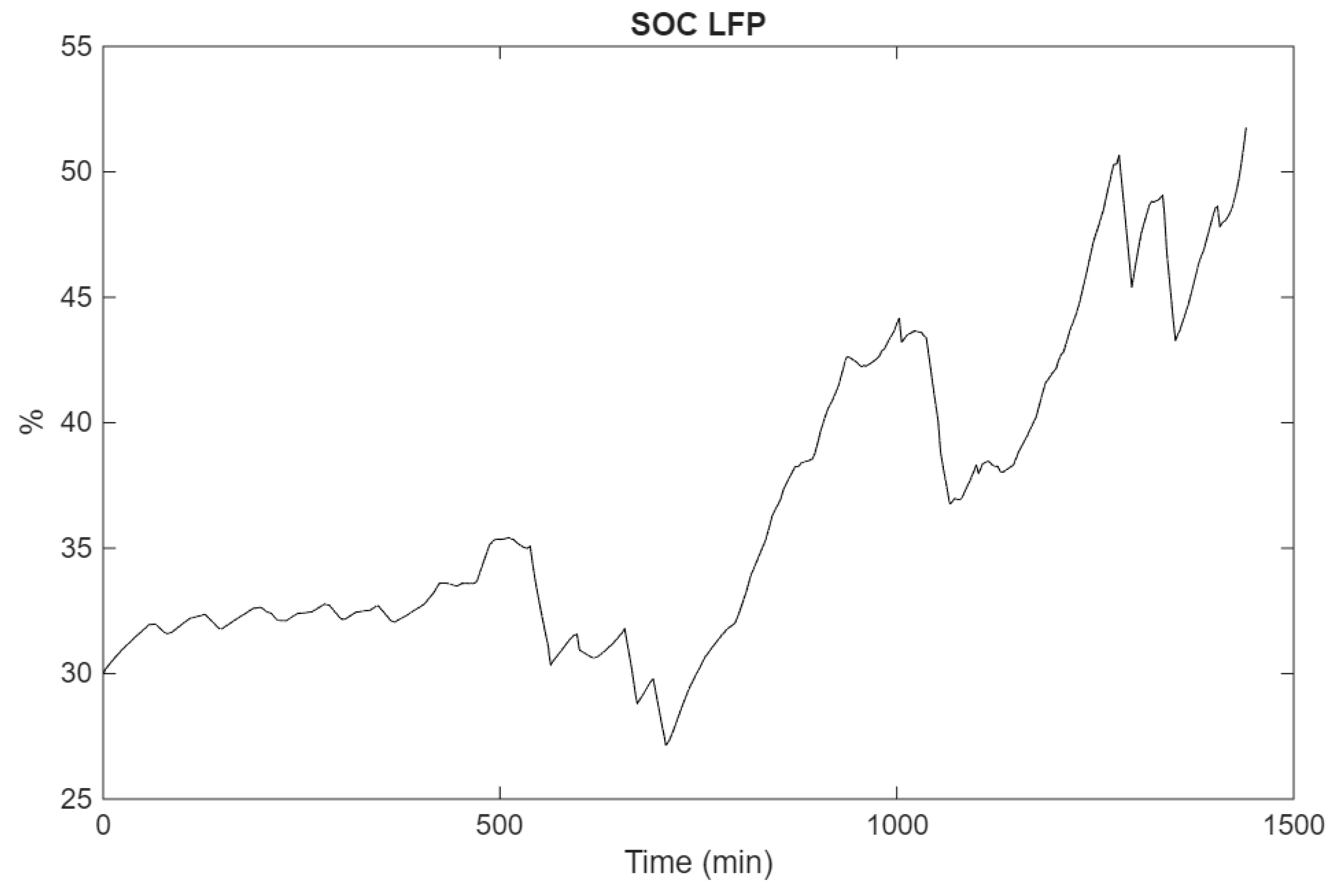
Figure 7.
Power delivered by LFP and FC in case C.
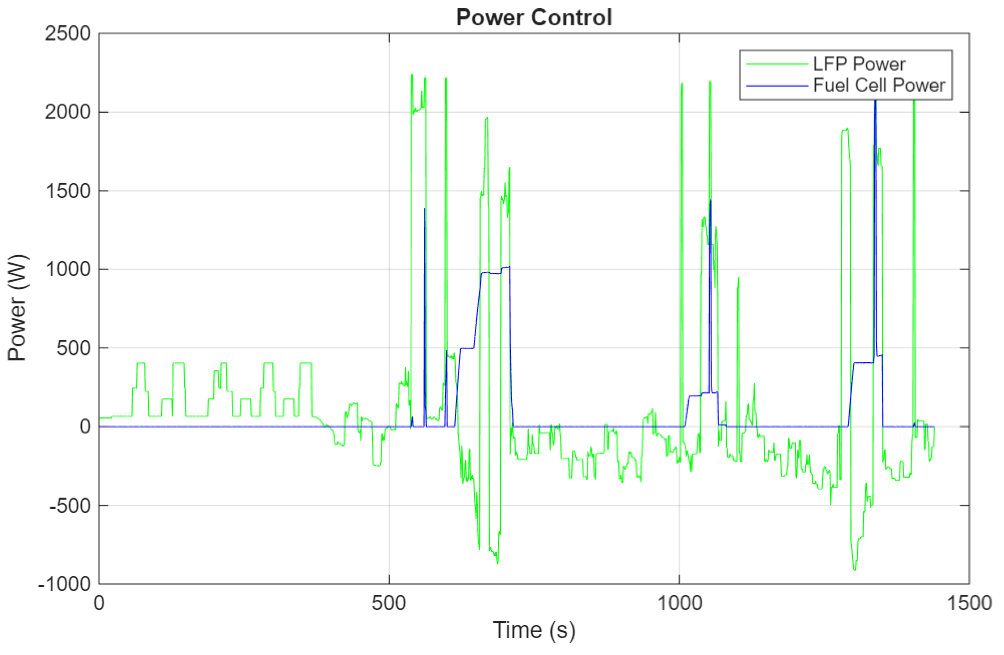
Figure 8.
LFP SOC value in case C.
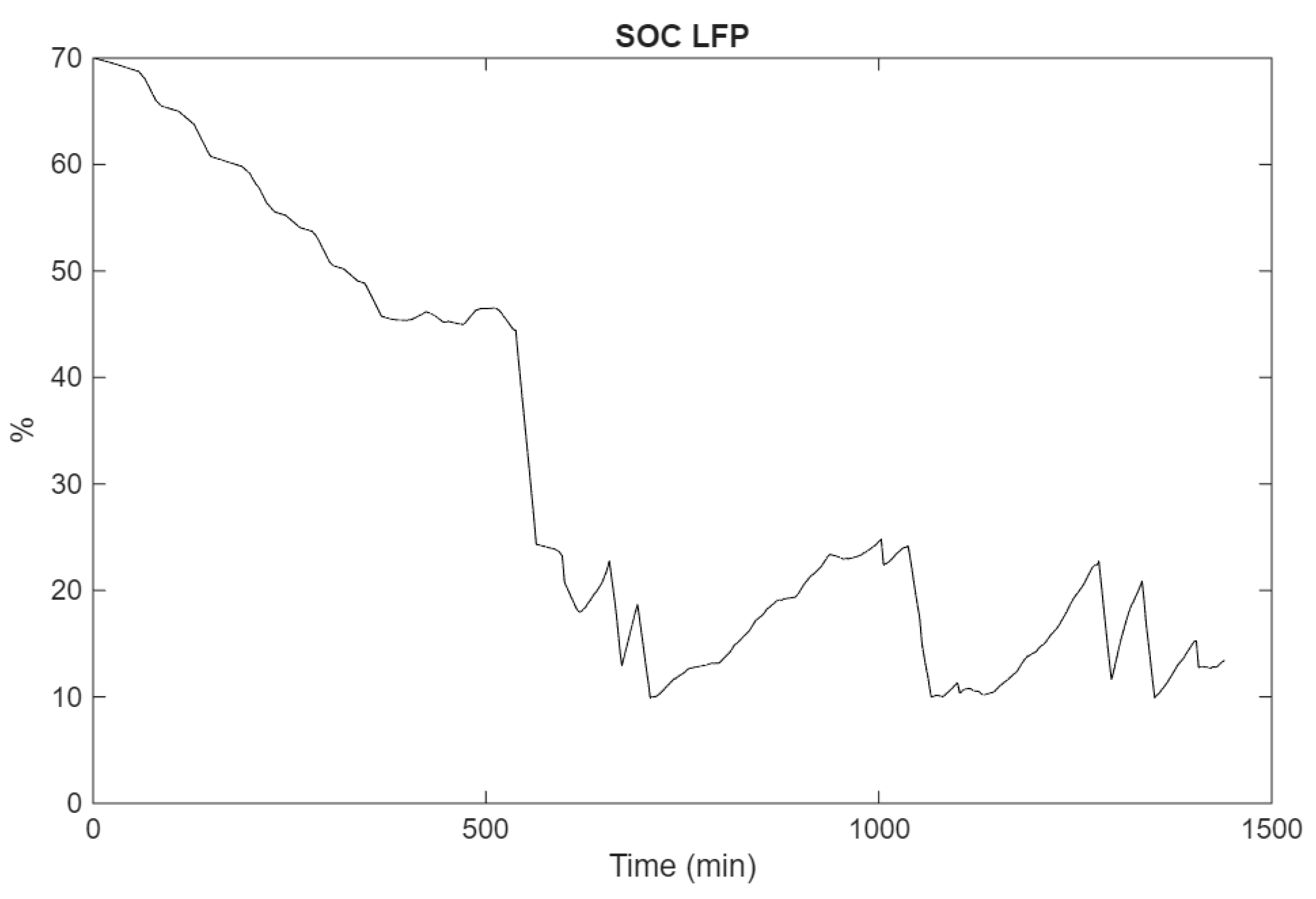
Figure 9.
Power delivered by LFP and FC in case C.
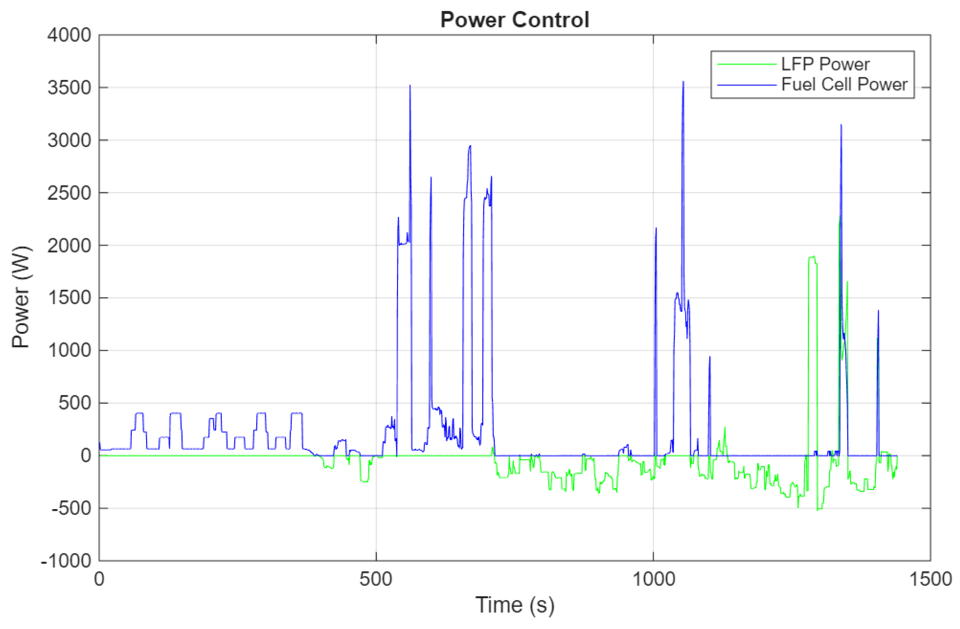
Figure 10.
LFP SOC value in case D.
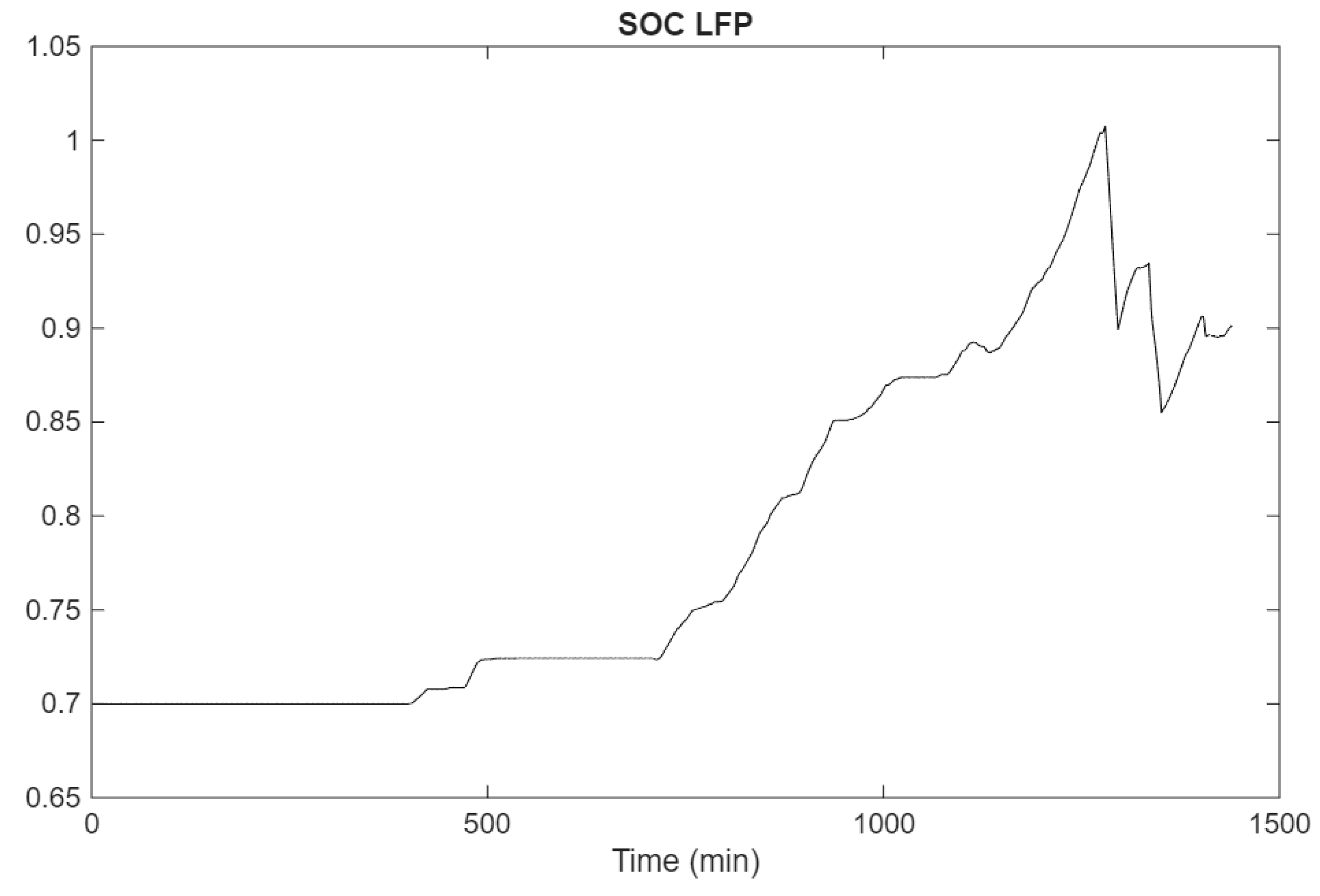
Figure 11.
Power delivered by LFP and FC in case E.
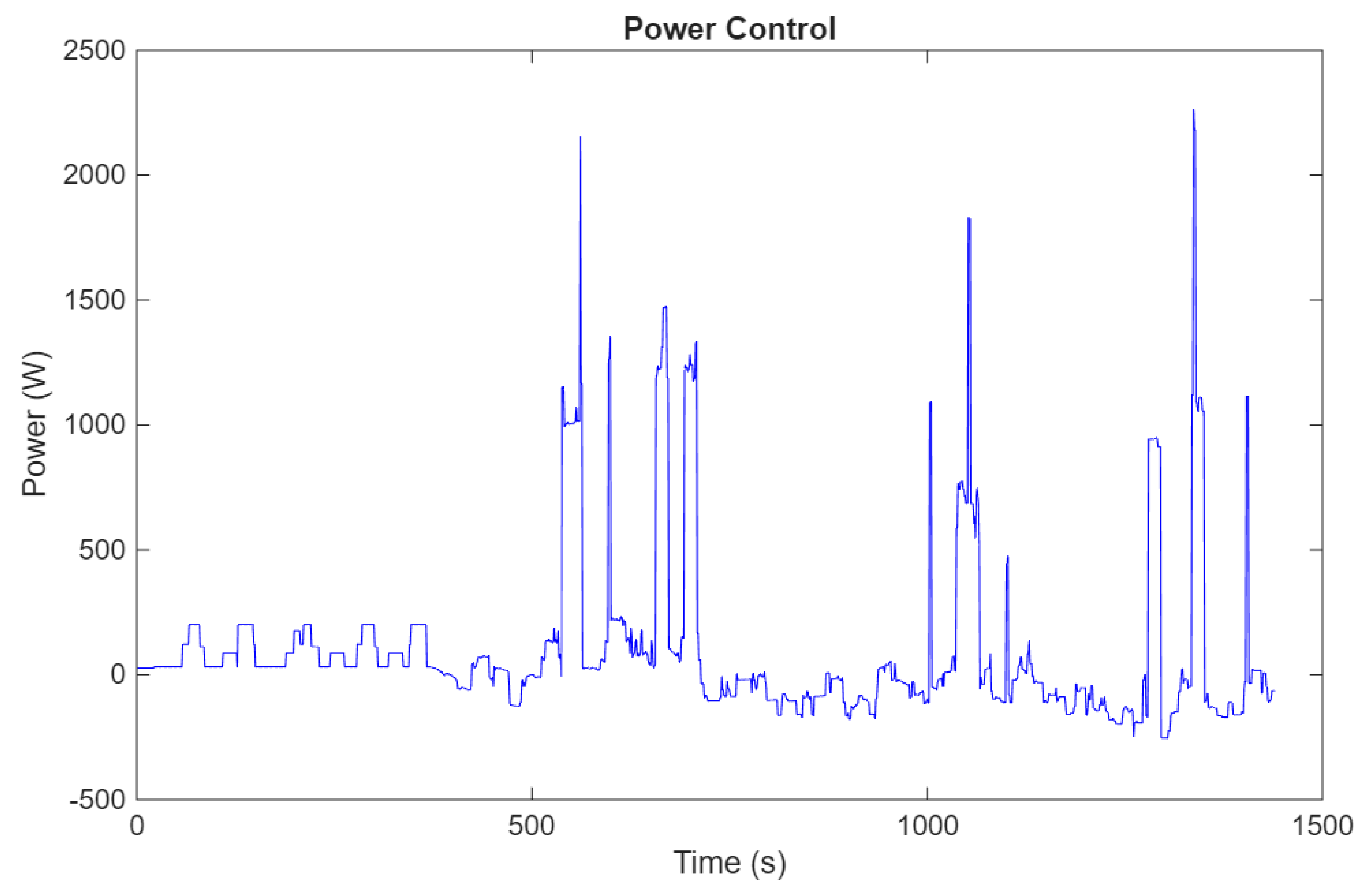
Figure 12.
LFP SOC value in case D.
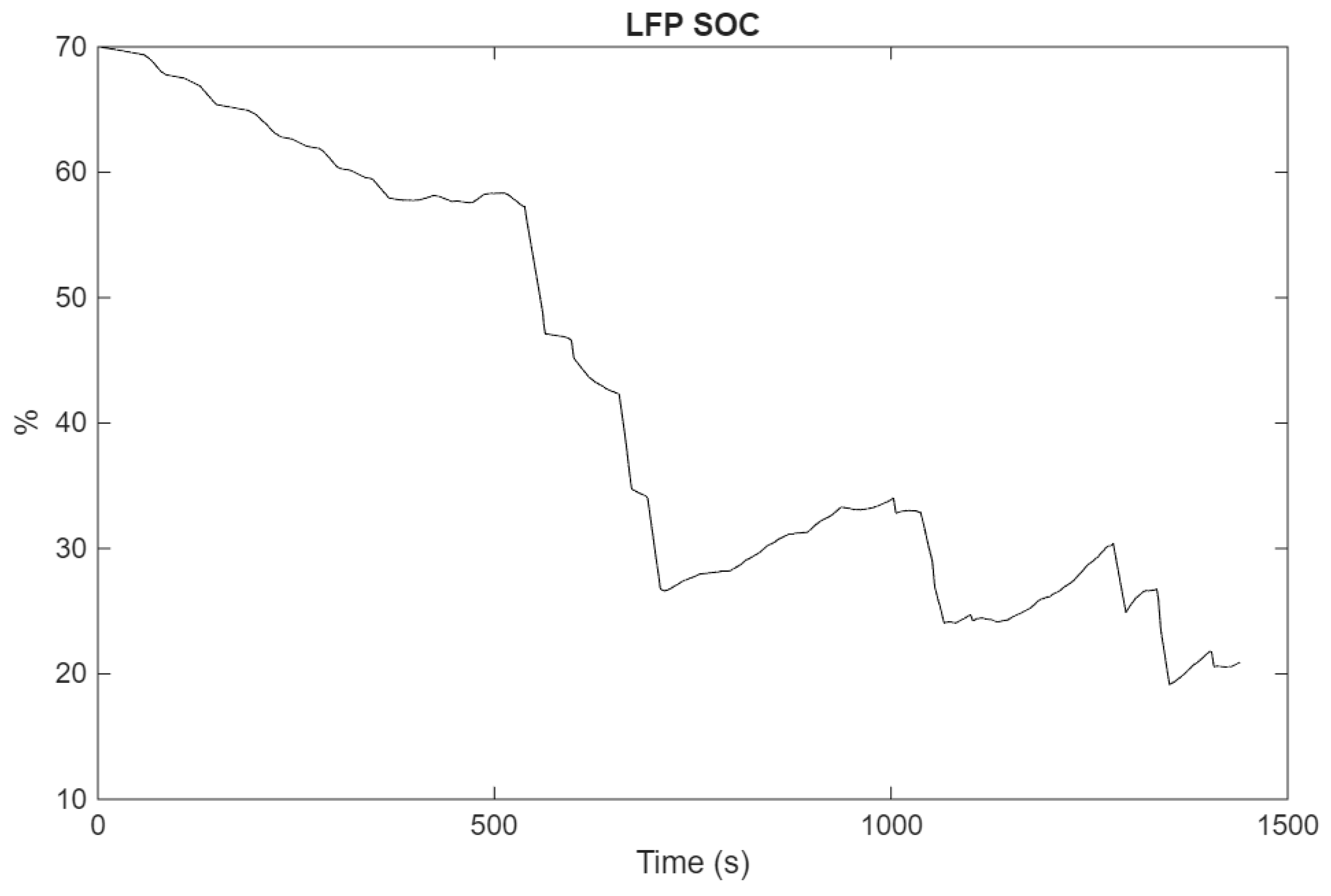

Table 1.
Value of the current weights of the LFP and FC and the LFP SOC value in the different cases.
Table 1.
Value of the current weights of the LFP and FC and the LFP SOC value in the different cases.
| Cases | LFP I weight | FC I weight | LFP SOC |
|---|---|---|---|
| Case A | 0 | 0 | 70% |
| Case B | 0 | 0 | 30% |
| Case C | 0 | 5 | 70% |
| Case D | 5 | 0 | 70% |
| Case E | - | - | 70% |
Disclaimer/Publisher’s Note: The statements, opinions and data contained in all publications are solely those of the individual author(s) and contributor(s) and not of MDPI and/or the editor(s). MDPI and/or the editor(s) disclaim responsibility for any injury to people or property resulting from any ideas, methods, instructions or products referred to in the content. |
© 2026 by the authors. Licensee MDPI, Basel, Switzerland. This article is an open access article distributed under the terms and conditions of the Creative Commons Attribution (CC BY) license (http://creativecommons.org/licenses/by/4.0/).
Copyright: This open access article is published under a Creative Commons CC BY 4.0 license, which permit the free download, distribution, and reuse, provided that the author and preprint are cited in any reuse.