
Submitted:
20 July 2026
Posted:
03 August 2026
You are already at the latest version
Abstract
Sodium-ion batteries (SIBs) are promising due to abundant, low-cost sodium, however, the larger ionic radius of Na+ severely hinders high-capacity, long-life anode materials. Molybdenum disulfide (MoS2) offers a high theoretical capacity but suffers from intrinsically poor electrical conductivity and severe volume fluctuation during cycling, necessitating effective modification strategies. A composite consisting of ZIF-8-derived carbon and MoS2 is successfully synthesized via co-precipitation, in-situ pyrolysis, and subsequent hydrothermal treatment using ZIF-8 as a precursor. The composite exhibits an increased specific surface area of 10.26 m2·g-1 and a reduced particle size compared with pristine MoS2. Electrochemical tests show that ZnS@NC@MoS2 delivers an initial discharge specific capacity of 523.3 mAh·g-1 at 100 mA·g-1 with an initial Coulombic efficiency of 75.3%, outperforming pristine MoS2. In rate capability tests, a specific capacity of 277.8 mAh·g-1 is achieved at a high current density of 5000 mA·g-1. The capacitive contribution increases with scan rate, reaching 87.75% at 8 mV·s-1. The enhanced electrochemical performance is attributed to the porous structure of the ZIF-8-derived carbon, which effectively suppresses MoS2 agglomeration, improves electrical conductivity, and facilitates Na+ diffusion. This work provides a promising strategy for designing high-performance anode materials for sodium-ion batteries.
Keywords:
sodium-ion batteries anode
; ZIF-8
; carbon composite
; molybdenum disulfide
; bimetallic sulfides
1. Introduction
With the intensification of the global energy crisis and climate challenges, the development of sustainable clean energy has become a broad consensus. Although solar and wind energy offer distinct advantages, their intermittency imposes stringent requirements on energy storage systems. Lithium-ion batteries have achieved considerable success in portable electronics and electric vehicles; however, the scarcity of lithium resources (crustal abundance of 0.0017%), their uneven geographical distribution, and escalating costs render them inadequate for large-scale energy storage applications[1,2,3,4]. Consequently, there is an urgent need to develop alternative energy storage technologies based on abundant and low-cost resources[5]. Sodium-ion batteries, benefiting from the rich availability of sodium (crustal abundance of 2.36%), low cost, and operational principles analogous to those of lithium-ion systems, are regarded as the most promising alternative. Moreover, the replacement of copper foil with aluminum foil for current collectors offers additional cost reductions[6,7]. Nevertheless, the ionic radius of sodium (1.02 Å) is substantially larger than that of lithium (0.76 Å), which results in sluggish insertion/extraction kinetics and severe structural stress, while conventional anode materials such as graphite exhibit extremely low sodium storage capacities[8,9]. Therefore, the development of anode materials with high specific capacity, long cycle life, and excellent rate capability remains a core challenge for the practical implementation of sodium-ion batteries[10].
Among the various anode material systems for sodium-ion batteries, transition metal sulfides have attracted considerable interest owing to their high theoretical specific capacity and abundant resource availability[11]. Among them, molybdenum disulfide (MoS2), as a typical two-dimensional layered transition metal sulfide, features a unique “sandwich” layered structure—in which Mo atomic layers are sandwiched between two S atomic layers, with strong intralayer covalent bonding and weak interlayer van der Waals forces[12]. This unique structural characteristic enables the reversible intercalation and deintercalation of sodium ions between the layers with negligible volume variation, thereby contributing to the preservation of structural stability of the material[13]. Furthermore, MoS2 delivers a high theoretical specific capacity of approximately 670 mAh·g-1, substantially exceeding that of conventional carbon-based anode materials, thus demonstrating significant application potential[14]. However, the practical application of MoS2 as an anode material for sodium-ion batteries is confronted with two major bottlenecks. First, the intrinsically low electronic conductivity of MoS2 substantially limits the rate capability and charge-transfer efficiency of the electrode[15]. Second, during repeated sodiation/desodiation cycles, MoS2 undergoes intercalation and conversion reactions, forming metallic Mo and Na2S, which are accompanied by substantial volume expansion and the accumulation of structural stress. This leads to structural degradation of the electrode, detachment of active material, and rapid capacity fading[16]. To address the aforementioned inherent drawbacks, researchers have explored a variety of modification strategies, including nanostructure design, heteroatom doping, phase engineering (e.g., 2H and 1T phases), and compositing with highly conductive materials [17]. Among these, constructing composites with carbon-based materials is considered one of the most effective and practically promising approaches—the carbon matrix not only provides a continuous conductive network but also effectively buffers the volume expansion of MoS2 upon cycling, thereby synergistically enhancing the rate capability and cycling stability of the electrode material[18].
Metal–organic frameworks (MOFs), as a class of crystalline porous materials self-assembled from metal ions/clusters and organic ligands via coordination bonds, have attracted extensive research interest in the field of electrochemical energy storage in recent years. MOFs exhibit notable advantages, including ultrahigh specific surface area, tunable pore structures, abundant active sites, and designable chemical compositions[19]. Upon high-temperature pyrolysis, the metal ions and organic ligands within MOFs are converted into metals/metal compounds and nitrogen-doped porous carbon, respectively, yielding a carbon-based composite that integrates high electrical conductivity, a porous architecture, and in-situ nitrogen doping[20]. This self-templating strategy not only retains the original polyhedral morphology of MOFs but also provides an ideal structural scaffold for the uniform loading of active species[21]. Among the diverse family of MOFs, ZIF-8 (Zeolitic Imidazolate Framework-8), self-assembled from Zn2+ ions and 2-methylimidazole linkers, yields upon pyrolysis a nitrogen-doped porous carbon (NC) that exhibits both high electrical conductivity and the distinctive rhombic dodecahedral morphology of the parent framework. In recent years, considerable progress has been made in the application of ZIF-8-derived carbon materials as anodes for sodium-ion batteries. Specifically, it has been demonstrated that tuning the carbonization temperature enables the optimization of the microstructure of ZIF-8-derived carbon, thereby leading to a marked enhancement in sodium storage performance[22]. Furthermore, ZIF-8-derived carbon has been shown to achieve a reversible capacity of up to 436.9 mAh·g-1[23]. It should be noted that although Yu et al. [17] have conducted preliminary explorations of this material system, their study exhibits notable deficiencies in the following critical aspects: (1) the absence of quantitative characterization of the Na+ diffusion coefficient; (2) the lack of systematic analysis regarding the scan-rate-dependent capacitive contribution behavior; and (3) the failure to elucidate the interfacial electric field between MoS2 and the carbon substrate, as well as its promotional role in charge transfer. These mechanistic gaps, in turn, precisely form the central motivation of the present study. The incorporation of ZIF-8-derived carbon into MoS2 holds promise for concurrently overcoming the two key limitations of MoS2—namely, its inferior electrical conductivity and substantial volume expansion. In this composite, the nitrogen-doped carbon matrix acts as a conductive backbone that accelerates electron transfer, and the porous architecture provides fast channels for Na+ diffusion; additionally, the physical confinement effect of the carbon layer efficiently prevents the aggregation and structural deterioration of MoS2 nanosheets during cycling[24]. Further quantitative evaluation was carried out by GITT. In addition, ZnS, which is generated in situ during the pyrolysis of ZIF-8, can form a bimetallic sulfide heterostructure with MoS2, providing additional synergistic enhancement of the electrochemical performance[23]. Therefore, the compositing strategy of ZIF-8-derived carbon with MoS2 is of substantial scientific significance and holds considerable promise for practical applications.
Against the above background and with the aim of addressing the mechanistic gaps left unresolved in the work of Yu et al. [17], the present study employs ZIF-8 as a precursor. Specifically, ZIF-8 templates were first synthesized via a coprecipitation method, followed by in-situ pyrolysis to obtain a ZIF-8-derived carbon matrix (denoted as ZIF-8@C). Subsequently, MoS2 nanoflowers were uniformly loaded onto the surface of the carbon matrix through a hydrothermal process, successfully yielding the ZnS@NC@MoS2 composite. Unlike previous reports, the emphasis of this work is placed on providing entirely new mechanistic insights, which include: (1) quantitative evaluation of the Na+ diffusion coefficient by means of the galvanostatic intermittent titration technique (GITT), revealing for the first time the ion-transport kinetic characteristics throughout the entire sodiation/desodiation process of this composite; (2) systematic analysis of the evolution of capacitive contribution over a wide scan-rate range from 0.2 to 8.0 mV·s-1, clarifying the origin of its high-rate capability; and (3) identification and confirmation of the interfacial electric field between MoS2 and the carbon substrate, based on binding-energy shifts in XPS, thus providing direct spectroscopic evidence for the charge-transfer enhancement mechanism. In addition, the composite’s structure and morphology were systematically characterized by XRD, SEM, Raman spectroscopy, and XPS, while its sodium-storage performance was comprehensively evaluated through cyclic voltammetry, galvanostatic charge-discharge tests, electrochemical impedance spectroscopy, capacitive-contribution analysis, and GITT. Through this in-depth and systematic investigation for sodium-ion batteries, we aim to establish a more complete mechanistic framework and theoretical basis for the design of high-performance MoS2/carbon composite anode materials.
2. Materials and Methods
First, the ZIF-8 precursor was prepared via a coprecipitation method. Specifically, 4.0 mmol of zinc acetate was dissolved in 100 mL of methanol to form solution A, while 20.0 mmol of 2-methylimidazole was dissolved in another 100 mL of methanol to form solution B. Solution B was then added to solution A under stirring, and the mixture was stirred for 24 h. The resulting ZIF-8 particles were collected by repeated centrifugation and dried under vacuum at 70 °C. Finally, the as-obtained ZIF-8 was annealed at 600 °C for 4 h under an argon atmosphere to yield the ZIF-8@C precursor.
For the subsequent composite synthesis, 1.442 g of (NH4)6Mo7O24·4H2O and 1.8 g of thiourea (CH4N2S) were dissolved together in 75 mL of distilled water. Then, 60 mg of the as-prepared ZIF-8@C was added to the solution, and after thorough stirring to ensure homogeneous dispersion, the mixture was transferred into a 100 mL Teflon-lined autoclave and heated at 200 °C for 24 h. After the autoclave had cooled to room temperature, the precipitate was collected by centrifugation, washed with deionized water and ethanol three to four times, and then dried at 60 °C. The dried product was ground to obtain the final ZnS@NC@MoS2 composite. A schematic illustration of the preparation process is presented in Figure A1.
3. Results
The XRD pattern shown in Figure A2 confirms the successful preparation of the ZIF-8 precursor. Figure 1a presents the XRD pattern of the ZnS@NC@MoS2 nanoflower spheres, characterizing the phase composition of the as-prepared sample. Five typical diffraction peaks are observed at 14.1°, 28.5°, 33.7°, 39.5°, and 58.9°, which correspond to the (002), (004), (101), (103), and (008) crystal planes of MoS2, respectively, in accordance with the PDF standard card No. 97-003-1067, Five typical diffraction peaks are observed at 28.6°, 33.1°, 47.5°, 59.1°, and 69.5°, which can be indexed to the (111), (200), (220), (222), and (400) planes of ZnS, respectively, according to PDF card No. 00-005-0566, indicating the presence of a trace amount of ZnS[25].
Raman spectroscopy was further employed to confirm the phase composition of the ZnS@NC@MoS2 composite. As shown in Figure 1b, the Raman spectrum exhibits characteristic peaks at 282 and 335 cm-1, which are assigned to ZnS, while the peaks at 376 and 403 cm-1 are attributed to MoS2[26]. Apart from the characteristic peaks of ZnS and MoS2, the Raman spectrum of the ZnS@NC@MoS2 composite (Figure 1c) exhibits the D band at 1323 cm-1 and the G band at 1575 cm-1. The intensity ratio (ID/IG) of these two bands is widely adopted to assess the graphitization degree of carbonaceous materials, and the measured value of 0.94 indicates that the contents of defective carbon and graphitic carbon are approximately equal. Unequivocally confirms the successful incorporation of the carbon matrix.
X-ray photoelectron spectroscopy (XPS) was employed to analyze the elemental valence states and chemical composition of the ZnS@NC@MoS2 composite, and the results are presented in Figure 2. In the high-resolution C 1s spectrum of the composite (Figure 2a), the peaks at 284.80, 286.46, and 288.58 eV are assigned to C–C, C–N, and C=O bonds[27], respectively. In the high-resolution N 1s spectrum of the ZnS@NC@MoS2 composite (Figure 2b), the peaks at 397.74, 399.96, and 401.96 eV are assigned to pyridinic N, pyrrolic N, and graphitic N, respectively; additionally, the peak at 395.24 eV corresponds to Mo 3p3/2[28]. In the high-resolution S 2p spectrum (Figure 2c), the peaks at 162.25 eV and 163.50 eV are assigned to the 2p3/2 and 2p1/2 spin–orbit components of S2-, respectively[29]. In the high-resolution Mo 3d spectrum of the ZnS@NC@MoS2 composite (Figure 2d), the peaks at 229.37, 232.49, and 235.36 eV are assigned to Mo4+ 3d3/2, Mo4+ 3d5/2, and Mo6+, respectively, indicating that molybdenum exists in mixed +4 and +6 valence states within the composite. Additionally, the peak at 226.57 eV is attributable to S 2s. Furthermore, compared with those of pristine MoS2, the binding energies of the S2⁻ 2p3/2, S2⁻ 2p1/2, Mo4+ 3d3/2, Mo4+ 3d5/2, and Mo6+ peaks in ZnS@NC@MoS2 are all positively shifted. This shift indicates the presence of an interfacial electric field between the MoS2 and the carbon substrate. Such an interfacial electric field elevates the binding energy of inner-shell electrons, thereby promoting rapid interfacial charge transfer.
The morphology of ZIF-8 is shown in Figure 3a and Figure 3b, which exhibits a rhombic dodecahedral structure with a particle size of approximately 1 μm. Figure 3c and Figure 3e present the carbonized ZIF-8, i.e., ZIF-8@C, revealing that the ZIF-8@C retains the rhombic dodecahedral shape, although a certain degree of distortion and shrinkage occurs after high-temperature carbonization, accompanied by a reduction in particle size. Figure 3f displays the morphology of the ZnS@NC@MoS2 composite, in which MoS2 nanoflowers are uniformly grown and wrapped on the surface of ZIF-8@C, forming homogeneous nanospheres. In comparison with the pure MoS2 shown in Figure 3g, the SEM images of ZnS@NC@MoS2 indicate that its average particle size is around 800 nm, which is substantially smaller than that of pristine MoS2. This observation suggests that the composite modification effectively suppresses the growth of MoS2 and increases the specific surface area of the material[30]. Furthermore, EDS elemental mapping was performed to characterize the elemental distribution within the composite, Figure 3h demonstrates the homogeneous distribution of Mo, S, and Zn elements across the observed region within the material.
To analyze the specific surface area of the samples, nitrogen adsorption–desorption measurements were performed on MoS2 and ZnS@NC@MoS2 under isothermal conditions.
Figure A3 presents the nitrogen adsorption–desorption isotherms of MoS2 and ZnS@NC@MoS2. Both isotherms exhibit pronounced hysteresis loops, characteristic of type IV isotherms. The BET specific surface areas are determined to be 9.17 m2·g-1 and 10.26 m2·g-1 for MoS2 and ZnS@NC@MoS2, respectively. A comparison indicates that the specific surface area of MoS2 is enhanced after compositing with NC. The larger surface area provides more active sites for the battery reactions, which is beneficial for improving the battery capacity[31].
Figure 4a and Figure 4b present the cyclic voltammetry (CV) curves of the MoS2 and ZnS@NC@MoS2 electrodes at a scan rate of 0.2 mV·s-1 within the potential window of 0.01–3.0 V. For both materials, the initial discharge curves exhibit distinct reduction peaks at approximately 0.77 and 0.71 V, along with a smaller reduction peak between 0.0 and 0.25 V. The peak observed at around 0.75 V is ascribed to the intercalation of Na+ into the MoS2 interlayers[32], with the reaction expressed as follows:
The peak at 0.60 V is ascribed to the formation of the solid electrolyte interphase (SEI) film[33]. The peaks below 0.25 V correspond to the conversion into Na2S and metallic Mo upon further Na+ intercalation[34], with the reaction expressed as follows:
During the second discharge process, new reduction peaks appear at around 1.8 V and 0.9 V, which are associated with the formation of Na2S and the combination of Na+ with metallic Mo. In the charging process, two anodic peaks are observed at approximately 0.9 V and 1.80 V, corresponding to the formation of NaxMoS2 and MoS2, respectively. In addition, a relatively distinct oxidation peak is observed at about 2.2 V for ZnS@NC@MoS2 during charging, which may be related to the formation of S.
As can be seen from Figure 4c and Figure 4d, the irreversible peak area of ZnS@NC@MoS2 is larger than that of MoS2, which is attributed to its higher specific surface area, leading to a greater irreversible capacity loss during SEI film formation[35]. In the subsequent cycling process, the CV curves of ZnS@NC@MoS2 at different cycle numbers almost overlap, indicating good stability and reversibility of the material for sodium storage[36].
In this study, the cycling performance of MoS2 and ZnS@NC@MoS2 was evaluated via galvanostatic charge–discharge tests. Figure 5a and Figure 5b present the galvanostatic charge–discharge profiles of the MoS2 and ZnS@NC@MoS2 electrodes, respectively, measured at a current density of 100 mA·g-1 within a potential window of 0.01–3.0 V. These profiles exhibit electrochemical features that are essentially consistent with those observed in the CV curves, with the charge/discharge plateaus corresponding to the voltages of the redox peaks in the CV curves. Specifically, four plateaus are discernible in the charge–discharge profiles: discharge plateaus at approximately 0.15 V, 0.75 V, and 0.90 V, and a pronounced charge plateau at around 1.80 V, which are in good agreement with the cathodic peaks at 0.15 V, 0.75 V, 1.8 V, and 0.9 V observed in the CV curves[37]. During the first three cycles, the ZnS@NC@MoS2 electrode exhibits a higher discharge specific capacity in each cycle compared to MoS2, which is consistent with the larger enclosed area of the CV curves shown in Figure 4a and Figure 4b. Moreover, the second and third charge–discharge curves of ZnS@NC@MoS2 show a relatively high degree of overlap, indicating good reversibility of the material[38].
The cycling performance of the ZnS@NC@MoS2 and MoS2 electrodes was further compared at a current density of 100 mA·g-1 (Figure 5c). The initial discharge specific capacities of the two materials are 619.1 and 497.7 mAh·g-1, respectively. After 50 cycles, the ZnS@NC@MoS2 electrode maintains a capacity of approximately 293.3 mAh·g-1, whereas the MoS2 electrode decays to about 241.7 mAh·g-1. Both the capacity and the retained capacity of ZnS@NC@MoS2 are higher than those of MoS2, indicating that ZnS@NC@MoS2 exhibits superior cycling performance. This improvement may be attributed to the synergistic effect arising from the good electrical conductivity of the carbonized ZIF-8, the special morphology provided by its polyhedral structure[39].
The rate capability of the ZnS@NC@MoS2 and MoS2 electrodes was also evaluated, as shown in Figure 5e. At current densities of 100, 200, 500, 1000, 2000, and 5000 mA·g-1, the reversible specific capacities of ZnS@NC@MoS2 are 396.8, 384.5, 369.0, 351.5, 327.9, and 277.8 mAh·g-1, respectively. At a high current density of 5 A·g-1, the discharge capacity of ZnS@NC@MoS2 is substantially higher than that of MoS2 (213.3 mAh·g-1). When the current density is returned to 0.1 A·g-1, the capacities of ZnS@NC@MoS2 and MoS2 recover to 412.5 and 371.8 mAh·g-1, respectively, demonstrating the superior rate capability of the modified composite material. The rate capability of ZnS@NC@MoS2 is further evidenced by the galvanostatic charge–discharge profiles at various current densities (Figure A4). Compared with pristine MoS2, the ZnS@NC@MoS2 composite derived from the ZIF-8 precursor exhibits markedly smaller variations in specific discharge capacity across different current rates, and its discharge curves are more closely grouped, which collectively confirm its superior rate capability. In recent years, extensive research has been devoted to anode materials for sodium-ion batteries. Accordingly, Figure 5f presents a detailed comparison of the electrochemical performance of metal sulfides as anodes, with a focus on studies that adopt strategies analogous to our work. It is evident that the rate capability of ZnS@NC@MoS2 surpasses that reported in most of the referenced literature; nevertheless, a certain gap still remains relative to the state-of-the-art performance levels[40,41,42,43,44].
Galvanostatic Intermittent Titration Technique (GITT) is a commonly used method for measuring the ionic diffusion coefficient in electrode materials, with its theoretical basis rooted in Fick's second law. During the test, a constant current pulse is applied to the battery, followed by a prolonged relaxation period to allow the electrode to reach a thermodynamic equilibrium state. The potential variation during the pulse and the steady-state potential after relaxation are recorded. By calculating the at different potentials, the bulk ion transport kinetics of the material can be evaluated[45]. The sodium-ion diffusion coefficient () can be calculated using Equation (3).
where τ is the pulse duration, nm is the amount of substance of the active material, Vm is the molar volume of the active material, S is the electrochemically active surface area, ΔEs is the potential change between two successive relaxation steps, and ΔEτ is the potential change during a single pulse step.
GITT was further employed to quantitatively evaluate the Na+ diffusion coefficient. The measurement procedure was as follows: starting from the fully sodiated state (0.01 V), a current pulse of 0.1 A·g-1 was applied for 600 s, followed by a relaxation period of 1800 s. This process was repeated until two complete desodiation/sodiation cycles were completed. The DNa+ values were calculated according to the equation. The GITT profiles of MoS2 and ZnS@NC@MoS2 are shown in Figure 6a and Figure 6c, respectively. Figure 6a displays two typical "pulse–relaxation–pulse–relaxation" segments, and the DNa+ values calculated at each point are presented in Figure 6b and Figure 6d. The average DNa+ values for MoS2 and ZnS@NC@MoS2 are 4.36×10⁻¹¹ cm2·s-1 and 1.40×10⁻¹⁰ cm2·s-1, respectively. After modification with ZIF-8 as the precursor, the sodium-ion diffusion coefficient increased to 3.21 times that of MoS2, indicating that the use of ZIF-8 as the precursor significantly enhances the Na+ transport kinetics of the composite material.
Finally, to further probe the effect of electrochemical impedance on the reaction kinetics of the composite materials during charging and discharging, electrochemical impedance spectroscopy (EIS) was performed on both samples. The EIS spectra for all samples exhibit three characteristic regions: an intercept in the high-frequency domain, a semicircle in the mid-frequency domain, and a straight line in the low-frequency domain. An equivalent circuit model was adopted to fit the EIS data for all samples, as illustrated in Figure A5. In the Nyquist plots, the high-frequency intercept on the real axis corresponds to the internal resistance (Rs) of the battery, the diameter of the mid-frequency semicircle reflects the charge-transfer resistance (Rct), and the low-frequency linear segment enables the determination of the Na+ diffusion coefficient within the battery[46]. The relevant calculation formula is presented as follows:
where DNa+ is the sodium-ion diffusion coefficient (m2·s-1), R is the gas constant (8.314 J/K·mol), T is the absolute temperature (K), N is the number of electrons transferred, F is the Faraday constant (96,500 C·mol-1), CNa+ is the bulk concentration (mol·m-3), σ is the Warburg coefficient, and Z′ is the real part of the impedance.
Figure 6e presents the Nyquist plots of MoS2 and ZnS@NC@MoS2 measured at the open-circuit potential (OCP) and after one cycle. Under both testing conditions, the ZnS@NC@MoS2 electrode exhibits a smaller semicircle radius in the mid-frequency region, indicating a lower charge-transfer resistance (Rct). At OCP, the Rct values for MoS2 and ZnS@NC@MoS2 are 234.8 Ω and 207.0 Ω, respectively; after one cycle, the Rct values of both materials decrease to 36.24 Ω and 19.50 Ω, respectively. These results demonstrate that ZnS@NC@MoS2 possesses a faster interfacial charge-transfer rate under both conditions.
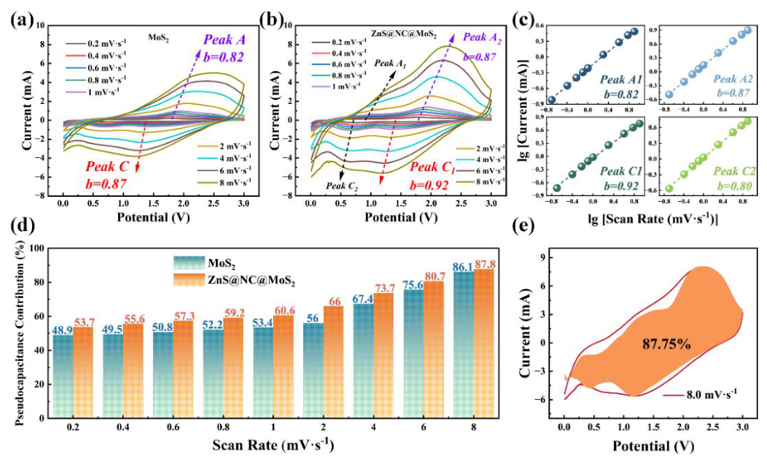
To demonstrate that capacitive charge storage contributes significantly to the overall charge storage in the present system, CV tests were performed on the ZnS@NC@MoS2 electrode at various scan rates ranging from 0.2 to 2.0 mV·s-1, with the results shown in Figure 7b. According to the relationship between the measured current and the scan rate:
The parameters a and b are variable, with b = 0.5 indicating a diffusion-controlled process and b= 1.0 suggesting that the system is predominantly governed by capacitive behavior; the specific value of b is determined from the slope of log(i) versus log(v) [47].
Furthermore, using Equations (8) and (9), the contribution ratio of pseudocapacitive behavior at various scan rates can be quantitatively calculated. [67] Here, k1v represents the pseudocapacitive contribution, k2v1/2 denotes the diffusion-controlled contribution, and the total current i(v) is the sum of these two components. In this work, based on the CV curves recorded at different scan rates, the aforementioned method is employed to analyze the pseudocapacitive contribution of the electrode material.
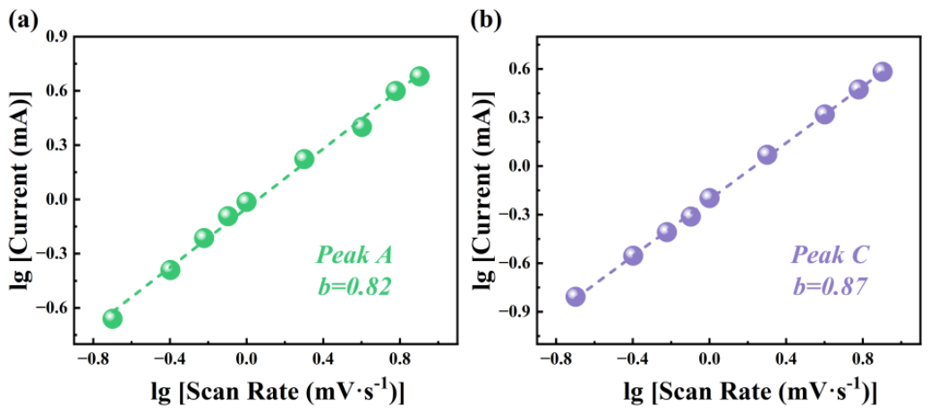
As depicted in Figure 7a and Figure 7b, the Anode 2 peak of ZnS@NC@MoS2 corresponds to the anodic peak of MoS2, with b-values of 0.87 (Figure 7c) and 0.82 (Figure A6), respectively. Similarly, the Cathode 1 peak of ZnS@NC@MoS2 corresponds to the cathodic peak of MoS2, exhibiting b-values of 0.92 and 0.87, respectively. All redox peaks of ZnS@NC@MoS2 possess b-values closer to 1.0, indicating that pseudocapacitive behaviour dominates the charge storage, which facilitates rapid Na+ insertion/extraction and superior rate capability. Moreover, ZnS@NC@MoS2 displays four redox peaks (Cathode 1, Cathode 2, Anode 1, and Anode 2) with b-values of 0.92, 0.80, 0.82, and 0.87, all approaching 1.0, whereas MoS2 exhibits only two. This suggests that the introduction of ZnS not only increases the number of active sites for energy storage, but also that these newly introduced sites are predominantly governed by surface-controlled pseudocapacitive behaviour, thereby enabling the composite to deliver a higher specific capacity than bare MoS2.
To quantitatively separate the capacitive and battery-type contributions to the total capacity, we analyzed the current response using the Equations (8) [48], where k1 and k2 are constants at a given potential, and the terms k1v and k2vl/2 correspond to the capacitive and battery-type (diffusion-controlled) contributions, respectively.
It can be observed from Figure 7d that the capacitive contribution to the specific capacity of the ZnS@NC@MoS2-based sodium-ion battery is remarkably high and increases proportionally with the scan rate. At scan rates of 0.2, 0.4, 0.6, 0.8, 1.0, 2.0, 4.0, 6.0, and 8.0 mV·s-1, the capacitive-dominated capacity percentages are 53.65%, 55.56%, 57.32%, 59.17%, 60.61%, 66.03%, 73.72%, 80.68%, and 87.75% (Figure 7e), respectively. This clearly demonstrates that the capacitive contribution rises progressively with increasing scan rate, indicating a fast Na+ diffusion kinetics within the designed ZnS@NC@MoS2 architecture. Such rapid diffusion is attributed to the large interlayer spacing of MoS2 and the presence of defect-induced pores, both of which facilitate ion transport. Furthermore, the porous MOF-derived matrix, based on bimetallic metal–organic framework carbon, effectively prevents particle aggregation and mitigates structural degradation during cycling, thereby delivering superior electrochemical performance.
4. Discussion
In this study, ZIF-8 was employed as a precursor to prepare templates via coprecipitation, followed by in-situ pyrolysis to yield a ZIF-8@C carbon matrix, onto which MoS2 nanoflowers were uniformly loaded through a hydrothermal process, successfully constructing the ZnS@NC@MoS2 composite. Sodium-ion battery tests reveal that the composite exhibits significantly enhanced cycling and rate performances compared to pristine MoS2: it delivers an initial discharge specific capacity of 523.3 mAh·g-1 at 100 mA·g-1, retains 293.3 mAh·g-1 after 50 cycles, and still achieves 277.8 mAh·g-1 at a high current density of 5 A·g-1. Its Na+ diffusion coefficient (1.40 × 10⁻¹⁰ cm2·s-1) is 3.21 times that of pristine MoS2, and the capacitive contribution reaches 87.75% at 8 mV·s-1, confirming its fast kinetic nature. This performance enhancement is mainly attributed to the synergistic effects of the porous MOF-derived carbon matrix: the N-doped conductive network ensures efficient electron transport, while the micro-mesoporous structure shortens Na+ diffusion pathways and facilitates electrolyte infiltration; meanwhile, the heterojunction interface formed between in-situ generated ZnS and MoS2 effectively lowers the charge-transfer energy barrier, improving both reaction reversibility and structural stability. Importantly, this work systematically discloses, for the first time, new mechanistic insights including the quantified 3.21-fold enhancement of the Na+ diffusion coefficient, the evolution of capacitive contribution over a wide scan-rate range (from 53.65% at 0.2 mV·s-1 to 87.75% at 8.0 mV·s-1), and the XPS-confirmed interfacial electric field that promotes charge transfer. Collectively, this study not only provides a feasible strategy for modifying transition-metal sulfide anodes, but also lays a theoretical and experimental foundation for developing sodium-ion battery anodes with high specific energy, long cycle life, and low cost.
Supplementary Materials
Supporting Information is available from the Wiley Online Library or from the author.
Author Contributions
Conceptualization, Xiaoyu Chen, Zhongke Yang, Haiping Liu and Kaiqi Zhang; methodology, Xiaoyu Chen; validation, Xiaoyu Chen, and Kaiqi Zhang; formal analysis, Xiaoyu Chen, Kaiqi Zhang, Haiping Liu and Zhongke Yang; investigation, Xiaoyu Chen, Kaiqi Zhang and Zhongke Yang; resources, Haiping Liu and Sifu Bi; data curation, Xiaoyu Chen; writing—original draft preparation, Xiaoyu Chen; writing—review and editing, Haiping Liu; visualization, Xiaoyu Chen, Kaiqi Zhang, Haiping Liu and Zhongke Yang; supervision, Haiping Liu and Sifu Bi; project administration, Haiping Liu and Sifu Bi; funding acquisition, Haiping Liu and Sifu Bi. All authors have read and agreed to the published version of the manuscript.
Funding
Please add: “This research received no external funding” or “This research was funded by NAME OF FUNDER, grant number XXX” and “The APC was funded by XXX”. Check carefully that the details given are accurate and use the standard spelling of funding agency names at https://search.crossref.org/funding. Any errors may affect your future funding.
Data Availability Statement
Data will be made available on request.
Conflicts of Interest
The authors declare that they have no known competing financial interests or personal relationships that could have appeared to influence the work reported in this paper.
Acknowledgments
This research is supported by Natural Science Foundation of Shandong Province (ZR2025MS238). The authors also highly appreciate HIT & Yun Shan Group Research and Development on Graphite Area.
Abbreviations
The following abbreviations are used in this manuscript:
| SIBs | Sodium-ion batteries |
| MoS2 | Molybdenum disulfide |
| MOFs | Metal–organic frameworks |
| ZIF-8 | Zeolitic Imidazolate Framework-8 |
| NC | nitrogen-doped porous carbon |
| ZIF-8@C | ZIF-8-derived carbon matrix |
Appendix A
Appendix A.1
Experimental Section
Chemicals: Zinc acetate dihydrate (C4H6O4Zn·2H2O, AR), Thiourea (CH4N2S, AR), and Ammonium molybdate ((NH4)2MoO4, AR), was purchased from Hu Shi Laboratory Equipment Co., Ltd. (Shanghai, China). NMP (C₅H₉NO), were purchased from Dongguan Canrd New Energy Technology Co., Ltd. (Dongguan, China), Methanol (CH4O, AR), was purchased from Tianjin Fuyu Fine Chemical Co., Ltd. (Tianjin, China), 2-methylimidazole (C4H6N2, 98%) were purchased from Shanghai Aladdin Biochemical Technology Co., Ltd. (Shanghai, China), Super P LI Conductive Carbon Black (Super P) was purchased from Hefei Kejing Material Technology Co., Ltd. (Hefei, China).Sodium sheets and electrolyte were purchased from Suzhou Duoduo Chemical Technology Co., Ltd. (Jiangsu, China).
Materials characterization: The phase composition and crystal structure of the prepared materials were analyzed using X-ray powder diffraction (XRD, Cu-Ka radiation, DX2700BH, Dandong Haoyuan, China) and Raman spectroscopy (RL633, Renishaw, UK). The microscopic morphology of the materials was analyzed using Scanning Electron Microscopy (SEM, EVO HD 15, Zeiss, Germany). The surface elements and valence information of the sample were obtained by X-ray photoelectron spectroscopy (XPS, K-Alpha, Thermo Fisher, USA) The specific surface area and pore size distribution were obtained through N2 adsorption-desorption tests (BSD-660S A3S, BEISHIDE Instrument, China).
Electrochemical measurements: The electrochemical performances of the materials were evaluated using CR2032 type coin cells. The active material, acetylene black, and polyvinylidene fluoride (PVDF) were dispersed in N-methylpyrrolidone (NMP) at a ratio of 8:1:1, stirred into a uniform slurry, coated onto a copper foil current collector, and fabricated into working electrodes. Cells were assembled in an Ar-filled glovebox. Sodium sheets were used as counter electrodes, glass fiber membranes as separators, and 1.0 M NaClO4 in (EC/DEC (1:1)+5% FEC) as the electrolyte. Galvanostatic charge-discharge tests were performed on the cells using the Land CT2001A battery testing system. Cyclic voltammetry (CV) and electrochemical impedance spectroscopy (EIS) tests were carried out on a CHI604E electrochemical workstation (Chinstruments, China).
Figure A1.
Schematic illustration of the preparation process of ZnS@NC@MoS2.
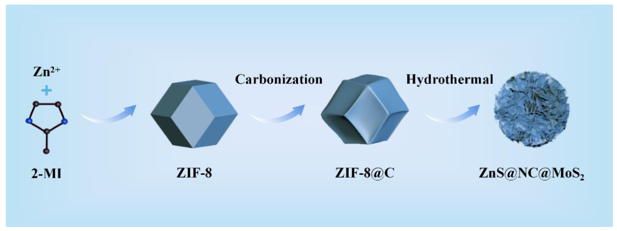
Figure A2.
XRD pattern of ZIF-8.
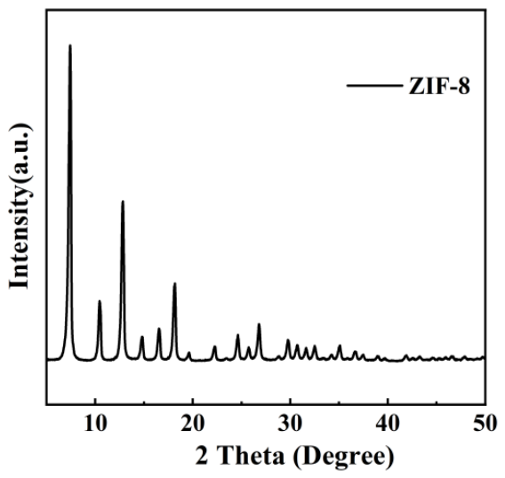
Figure A3.
Nitrogen adsorption–desorption isotherms: (a) MoS2; (b) ZnS@NC@MoS2.
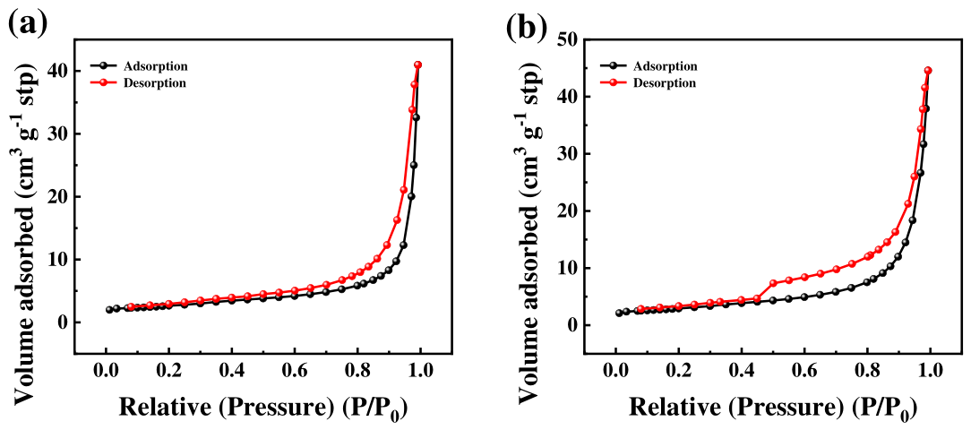
Figure A4.
Charge–discharge curves at various current densities: (a) MoS2; (b) ZnS@NC@MoS2.
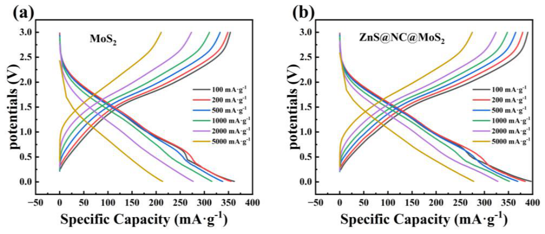
Figure A5.
Equivalent circuit model for EIS fitting.
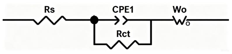
Figure A6.
the corresponding b-values of MoS2 derived from the CV curves at different scan rates: (a) Peak A, (b) Peak C.
Figure A6.
the corresponding b-values of MoS2 derived from the CV curves at different scan rates: (a) Peak A, (b) Peak C.
References
- Zhao, L.; Zhang, T.; Li, W.; Li, T.; Zhang, L.; Zhang, X.; Wang, Z. Engineering of Sodium-Ion Batteries: Opportunities and Challenges. Engineering 2023, 24, 172–183. [Google Scholar] [CrossRef]
- Wanison, R.; Syahputra, W.N.H.; Kammuang-lue, N.; Sakulchangsatjatai, P.; Chaichana, C.; Shankar, V.U.; Suttakul, P.; Mona, Y. Engineering Aspects of Sodium-Ion Battery: An Alternative Energy Device for Lithium-Ion Batteries. J. Energy Storage 2024, 100, 113497. [Google Scholar] [CrossRef]
- Phogat, P.; Dey, S.; Wan, M. Comprehensive Review of Sodium-Ion Batteries: Principles, Materials, Performance, Challenges, and Future Perspectives. Mater. Sci. Eng. B 2025, 312, 117870. [Google Scholar] [CrossRef]
- Singh, A.N.; Islam, M.; Meena, A.; Faizan, M.; Han, D.; Bathula, C.; Hajibabaei, A.; Anand, R.; Nam, K. Unleashing the Potential of Sodium-Ion Batteries: Current State and Future Directions for Sustainable Energy Storage. Adv. Funct. Mater. 2023, 33, 2304617. [Google Scholar] [CrossRef]
- Habib, L.; Suo, G.; Habib, N.; Aqdas, M.; Lin, C.; Li, J.; Javed, S. MoS2-Based Anodes for Sodium-Ion Batteries: Recent Developments and Key Engineering Approaches. J. Energy Storage 2025, 139, 118821. [Google Scholar] [CrossRef]
- Du, F.-X.; Liu, S.-L.; Li, Y.; Wang, J.-K.; Zhang, P. Facile Synthesis of MoS2/N-Doped Carbon as an Anode for Enhanced Sodium-Ion Storage Performance. Ionics 2023, 29, 5183–5193. [Google Scholar] [CrossRef]
- Tao, W.; Chen, J.; Xu, C.; Liu, S.; Fakudze, S.; Wang, J.; Wang, C. Nanostructured MoS2 with Interlayer Controllably Regulated by Ionic Liquids/Cellulose for High-Capacity and Durable Sodium Storage Properties. Small 2023, 19, 2207397. [Google Scholar] [CrossRef] [PubMed]
- Wu, Y.; Xu, Q.; Huang, L.; Huang, B.; Hu, P.; Xiao, F.; Li, N. Encapsulation of Sulfur in MoS2-Modified Metal-Organic Framework-Derived N, O-Codoped Carbon Host for Sodium–Sulfur Batteries. J. Colloid Interface Sci. 2024, 654, 649–659. [Google Scholar] [CrossRef] [PubMed]
- Editorial Board. J. Energy Storage 2023, 69, 108107. [CrossRef]
- Jia, H.; Wang, Y.; Zhao, S.; Wang, H.; Ju, N.; Zhang, X.; Li, H.; Sun, Z.; Sun, H. Fe, Ni-Modified ZIF-8 as a Tensive Precursor to Derive N-Doped Carbon as Na and Li-Ion Batteries Anodes. Nanotechnology 2023, 34, 085401. [Google Scholar] [CrossRef] [PubMed]
- Liao, W.-L.; Abdelaal, M.M.; Amirtha, R.-M.; Fang, C.-C.; Yang, C.-C.; Hung, T.-F. In Situ Construction of Nitrogen-Doped and Zinc-Confined Microporous Carbon Enabling Efficient Na+-Storage Abilities. Int. J. Mol. Sci. 2023, 24, 8777. [Google Scholar] [CrossRef] [PubMed]
- Kim, K.; Jeon, S.; Kim, H.-S.; Seo, H.; Kim, H.; Doeff, M.M.; Woo, S.-G.; Kim, J.-H. Superior Metal Storage Behavior of Zn-Containing Porous Carbon Nanostructures for Na and Li Metal Batteries. J. Mater. Chem. A 2023, 11, 7276–7285. [Google Scholar] [CrossRef]
- Ali, Z.; Shafqat, M.B.; Ahsan, M.T.; Ali, M.; Saeed, A.; Hussain, R.; Noor, T.; Javed, S. A Multichambered Carbon Based Electrode Materials to Realize Efficient Sodium-Ion Batteries. J. Energy Storage 2025, 106, 114804. [Google Scholar] [CrossRef]
- Bai, J.; Zhao, B.; Wang, X.; Ma, H.; Li, K.; Fang, Z.; Li, H.; Dai, J.; Zhu, X.; Sun, Y. Yarn Ball-like MoS2 Nanospheres Coated by Nitrogen-Doped Carbon for Enhanced Lithium and Sodium Storage Performance. J. Power Sources 2020, 465, 228282. [Google Scholar] [CrossRef]
- Cai, J.; Liu, C.; Tao, S.; Cao, Z.; Song, Z.; Xiao, X.; Deng, W.; Hou, H.; Ji, X. MOFs-Derived Advanced Heterostructure Electrodes for Energy Storage. Coord. Chem. Rev. 2023, 479, 214985. [Google Scholar] [CrossRef]
- Huang, J.; Wu, Z.; Zeng, W.; Xu, Z.; Hu, L.; Wu, Y.; Lin, X. Zeolitic Imidazolate Framework Derivatives as Anode Materials for Sodium and Potassium-Ion Batteries: A Mini Review. CrystEngComm 2024, 26, 1049–1066. [Google Scholar] [CrossRef]
- Yu, J.; Fan, J.; Zhang, H.; Yue, J.; Tang, X.; Ma, Z. Partially Carbonized Strategy of ZIF-8 for the Fabrication of ZnS/NC@MoS2 Anode Material : Towards High-Performance Li+/Na+ Storage. J. Power Sources 2026, 672, 239615. [Google Scholar] [CrossRef]
- Xie, X.; Huang, K.; Wu, X.; Wu, N.; Xu, Y.; Zhang, S.; Zhang, C. Binding Hierarchical MoSe2 on MOF-Derived N-Doped Carbon Dodecahedron for Fast and Durable Sodium-Ion Storage. Carbon 2020, 169, 1–8. [Google Scholar] [CrossRef]
- Luo, L.; Qian, X.; Wang, X. Bimetallic Metal-Organic Frameworks and Their Derivatives for Electrochemical Energy Conversion and Storage: Recent Progress, Challenges and Perspective. J. Energy Storage 2024, 98, 113052. [Google Scholar] [CrossRef]
- Yang, C.-Y.; Lang, J.-P. Diverse MOFs-Derived Carbon-Based Materials for Advanced Electrochemical Energy Applications. EnergyChem 2025, 7, 100163. [Google Scholar] [CrossRef]
- Zhao, X.; Liu, N.; Mu, C.; Qin, B.; Wang, L. Pb Nanospheres Encapsulated in Metal–Organic Frameworks-Derived Porous Carbon as Anode for High-Performance Sodium-Ion Batteries. J. Colloid Interface Sci. 2024, 669, 647–656. [Google Scholar] [CrossRef] [PubMed]
- Ma, H.; Yin, B.; Ye, T.; Egun, I.L.; Li, Y.; Zhang, X.; He, H. Regulating Open Pores to Engineer Closed Pores in ZIF-8-Derived Hard Carbon for High-Plateau-Capacity Sodium-Ion Batteries. J. Colloid Interface Sci. 2026, 702, 139042. [Google Scholar] [CrossRef] [PubMed]
- Kim, K.; Choi, J.; Nam, S. Structural Effect of ZIF-8 Derived Carbon on Sodium-Ion Storage Behavior. Carbon Lett. 2025, 35, 3059–3068. [Google Scholar] [CrossRef]
- Sun, J.; Xuan, H.; Zhang, C.; An, H.; Luo, W. Synergistically Controlled Nest-Shaped Microporous Silicon Anode with a Thin-Film Coating and a Hard Carbon Nanotemplate Obtained from ZIF-67 for Highly Stable Lithium-Ion Batteries. Energies 2026, 19, 3039. [Google Scholar] [CrossRef]
- Wang, P.; Gou, W.; Jiang, T.; Zhao, W.; Ding, K.; Sheng, H.; Liu, X.; Xu, Q.; Fan, Q. An Interlayer Spacing Design Approach for Efficient Sodium Ion Storage in N-Doped MoS2. Nanoscale Horiz. 2023, 8, 473–482. [Google Scholar] [CrossRef] [PubMed]
- Gray, E.L.; Lee, J.-I.; Yang, Z.J.; Wang, Y.; Chhowalla, M. In Situ Raman Mapping of Electrochemical Sodium Intercalation and Phase Stability in MoS2 for Sodium-Ion Batteries. ACS Appl. Nano Mater. 2026, 9, 296–304. [Google Scholar] [CrossRef]
- Xu, X.; Robertson, S.J.; Yang, T.; Chen, F.; Geng, X.; Wang, Y.; Ji, F.; Sun, C.; Chen, S.; Shao, M.; et al. Interfacial Space Charge Design with Desired Electron Density to Enhance Sodium Storage of MoS2@Nb2O5 Anode. Nano Energy 2024, 127, 109739. [Google Scholar] [CrossRef]
- Sun, D.; Lin, S.; Kuai, S.; Zhang, T.; Liu, L.; Zhao, J.; Zhou, X.; Liu, W.; Xu, B. Interfacial Mo-N Bonding Enhancement of N-Doped Carbon Nanosheets-Stabilized Ultrafine MoS2 Enable Ultrafast and Durable Sodium Ion Half/Full Batteries. Chem. Eng. J. 2024, 501, 157786. [Google Scholar] [CrossRef]
- Kulka, A.; Hanc, A.; Walczak, K.; Płotek, J.; Sun, J.; Lu, L.; Borca, C.; Huthwelker, T. Direct Evidence of an Unanticipated Crystalline Phase Responsible for the High Performance of Few-Layered-MoS2 Anodes for Na-Ion Batteries. Energy Storage Mater. 2022, 48, 314–324. [Google Scholar] [CrossRef]
- Yu, J.; Fan, J.; Zhang, H.; Yue, J.; Tang, X.; Ma, Z. Partially Carbonized Strategy of ZIF-8 for the Fabrication of ZnS/NC@MoS2 Anode Material : Towards High-Performance Li+/Na+ Storage. J. Power Sources 2026, 672, 239615. [Google Scholar] [CrossRef]
- Ma, X.; Zhao, J.; Jiao, R.; Mudassir, M.A.; Xu, X.; Gao, Y.; Liu, Y.; He, W.; Cui, J.; Zhao, X. Unveiling the Role of MoS2 Hollow Nanospheres on Lignite-based Carbon for Enhanced Sodium-ion Battery Performance. Rare Met. 2025, 44, 4801–4814. [Google Scholar] [CrossRef]
- Wang, D.; Xie, K.; Wang, T.-T.; Zhou, J.; Zhao, F.; Shi, Z. In Situ Growth of Vanadium-Doped Molybdenum Disulfide on Graphene as a Sodium-Ion Battery Anode with Superior Rate Performance. Chem. Eng. J. 2026, 541, 177423. [Google Scholar] [CrossRef]
- Ma, C.; Li, H.; Li, Z.; Han, G.; Tang, X.; Qian, J.; Chen, R. Atomic Co-Driven Catalysis in MoS2 for Accelerated Charge Transfer and Stable Interfacial Chemistry in Sodium-Ion Batteries. Energy Storage Mater. 2025, 82, 104611. [Google Scholar] [CrossRef]
- Fu, Z.; Shao, X.; Chen, B.; Guo, D.; Xia, Y.; Wei, X.; Hou, H.; Sun, J. Bulk-to-Interface Engineering of MoS2 via Iodine Doping: Synchronizing Phase Transition and Interfacial Chemistry for Advanced Sodium Storage. Prog. Nat. Sci. Mater. Int. 2025, 35, 963–970. [Google Scholar] [CrossRef]
- Zhang, Z.; Zhu, J.; Zhang, M.; Xie, G.; Huang, D.; Wang, H.; Liu, K.; Zheng, F.; Li, Q.; Pan, Q. Construction of Sponge-like MoS2/NC Composite as High Rate and Long Cycle Life Anode Materials for Sodium Ion Batteries. J. Energy Storage 2026, 146, 120186. [Google Scholar] [CrossRef]
- Qian, K.; Li, Y.; Zou, Q.; Cao, K.; Li, Z. SOH and RUL Estimation for Lithium-Ion Batteries Based on Partial Charging Curve Features. Energies 2025, 18, 3248. [Google Scholar] [CrossRef]
- Yang, Y.; Zheng, F.; Wang, L.; Liu, Y. 3D MoS2/Graphene Oxide Integrated Composite as Anode for High-Performance Sodium-Ion Batteries. Sci. Rep. 2024, 14, 19231. [Google Scholar] [CrossRef] [PubMed]
- Yang, Y.; Wang, L.; Suo, C.; Liu, Y. Macroporous C@MoS2 Composite as Anodes for High-Performance Sodium-Ion Batteries. RSC Adv. 2025, 15, 21051–21060. [Google Scholar] [CrossRef] [PubMed]
- Zhou, J.; Ji, T.; Xu, S.; Wang, X.; Wang, J.; Tang, Y.; Li, Y.; Yin, W.; Ji, H.; Shi, S.; et al. Synergistically Designed Carbon-Free MoS2 /MoO2 Heterostructure Anodes with Interfacial Covalent Bonds for High-Rate Sodium-Ion Batteries. Chem. – Eur. J. 2025, 31, e202500589. [Google Scholar] [CrossRef] [PubMed]
- Wu, J.; Liu, J.; Cui, J.; Yao, S.; Ihsan-Ul-Haq, M.; Mubarak, N.; Quattrocchi, E.; Ciucci, F.; Kim, J.-K. Dual-Phase MoS2 as a High-Performance Sodium-Ion Battery Anode. J. Mater. Chem. A 2020, 8, 2114–2122. [Google Scholar] [CrossRef]
- He, T.; Kang, X.; Li, G.; Dang, H.; Ran, F. Sodium in Situ Modulated Phase Transition to Construct Iron/Vanadium Bimetallic Sulfide Anodes for “Fast-Charging” Sodium-Ion Batteries. EES Batter. 2025, 1, 1544–1556. [Google Scholar] [CrossRef]
- Zhang, Y.; Chen, J.; Kang, T.; Yang, W.; Zou, H.; Chen, S. MoS2 Spheres Covered with a Few Layers of MXene as a High-Performance Anode for Sodium-Ion Batteries. Dalton Trans. 2024, 53, 16733–16739. [Google Scholar] [CrossRef] [PubMed]
- Wang, T.; Yao, K.; Hua, Y.; Shankar, E.G.; Shanthappa, R.; Yu, J.S. Rational Design of MXene-MoS2 Heterostructure with Rapid Ion Transport Rate as an Advanced Anode for Sodium-Ion Batteries. Chem. Eng. J. 2023, 457, 141363. [Google Scholar] [CrossRef]
- Yang, S.H.; Park, S.-K.; Park, G.D.; Kim, J.H.; Kang, Y.C. Rational Synthesis of Uniform Yolk–Shell Ni–Fe Bimetallic Sulfide Nanoflakes@porous Carbon Nanospheres as Advanced Anodes for High-Performance Potassium-/Sodium-Ion Batteries. Chem. Eng. J. 2021, 417, 127963. [Google Scholar] [CrossRef]
- Nowak, A.P.; Rutecki, P.; Szkoda, M.; Trzciński, K. Determination of Sodium Ion Diffusion Coefficient in Tin Sulfide@Carbon Anode Material Using GITT and EIS Techniques. Energies 2024, 17, 3233. [Google Scholar] [CrossRef]
- Ai, H.; Zhou, W.; Zhou, Q.; Hong, Y.; Li, X.; Xie, J.; Du, K. In Situ Synthesis of Cellulose/Carbon Nanotubes/Molybdenum Disulfide Composite with Ultrahigh Capacity and Enhanced Coulombic Efficiency for Sodium Ion Battery. J. Power Sources 2025, 646, 237262. [Google Scholar] [CrossRef]
- Yao, K.; Xu, Z.; Huang, J.; Ma, M.; Fu, L.; Shen, X.; Li, J.; Fu, M. Bundled Defect-Rich MoS2 for a High-Rate and Long-Life Sodium-Ion Battery: Achieving 3D Diffusion of Sodium Ion by Vacancies to Improve Kinetics. Small 2019, 15, 1805405. [Google Scholar] [CrossRef] [PubMed]
- Khanam, Z.; Luo, L.; Mushtaq, M.; Li, J.; Yang, H.; Ouyang, T.; Balogun, M.-S.; Pan, A. Robust Pseudocapacitive Na+ Intercalation Induced by MoS2 on Active Mo2C Current Collector Interface for High Areal Capacity Sodium-Ion Batteries. Nano Energy 2024, 125, 109590. [Google Scholar] [CrossRef]
Figure 1.
(a) XRD pattern of the ZnS@NC@MoS2 composite; (b) Raman spectrum of the ZnS@NC@MoS2 composite in the range of 200–500 cm-1; (c) Raman spectrum of the ZnS@NC@MoS2 composite in the range of 1100–2000 cm-1.
Figure 1.
(a) XRD pattern of the ZnS@NC@MoS2 composite; (b) Raman spectrum of the ZnS@NC@MoS2 composite in the range of 200–500 cm-1; (c) Raman spectrum of the ZnS@NC@MoS2 composite in the range of 1100–2000 cm-1.
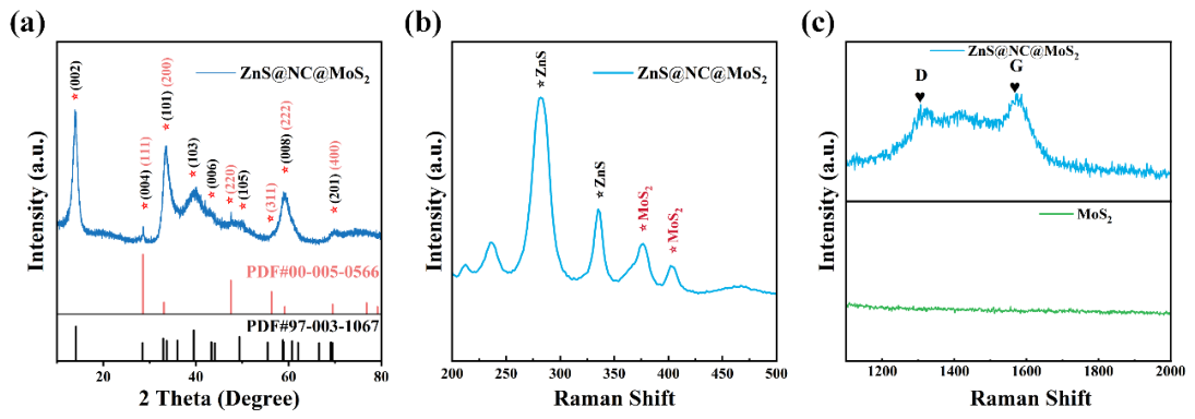
Figure 2.
XPS spectra of the ZnS@NC@MoS2 composite: (a) C 1s, (b) N 1s; Comparative XPS spectra of ZnS@NC@MoS2 and MoS2: (c) S 2p, and (d) Mo 3d.
Figure 2.
XPS spectra of the ZnS@NC@MoS2 composite: (a) C 1s, (b) N 1s; Comparative XPS spectra of ZnS@NC@MoS2 and MoS2: (c) S 2p, and (d) Mo 3d.
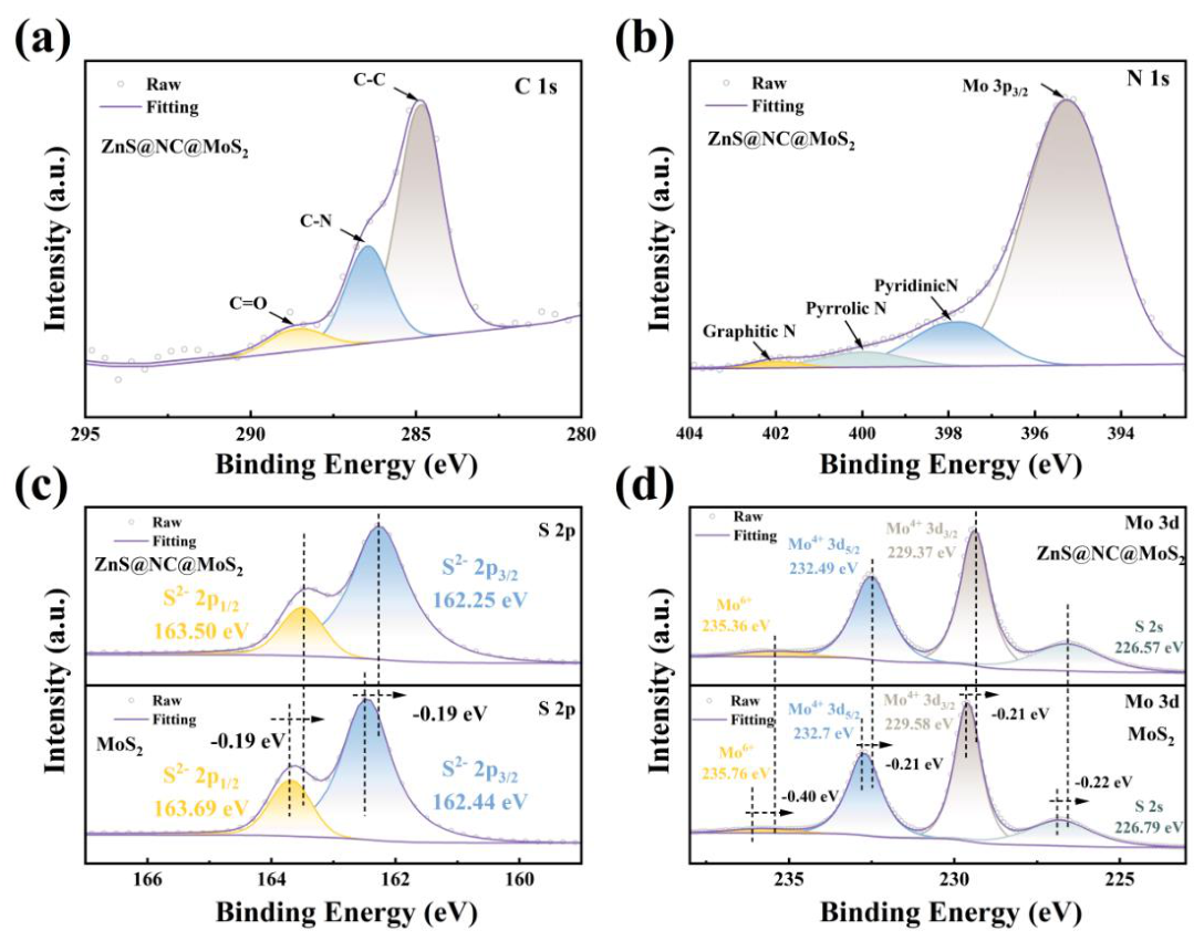
Figure 3.
SEM images of (a) ZIF-8, (b) a single ZIF-8 particle, (c) ZIF-8@C, (d, e) individual ZIF-8@C particles, (f) ZnS@NC@MoS2, (h) EDS elemental mappings of ZnS@NC@MoS2.
Figure 3.
SEM images of (a) ZIF-8, (b) a single ZIF-8 particle, (c) ZIF-8@C, (d, e) individual ZIF-8@C particles, (f) ZnS@NC@MoS2, (h) EDS elemental mappings of ZnS@NC@MoS2.
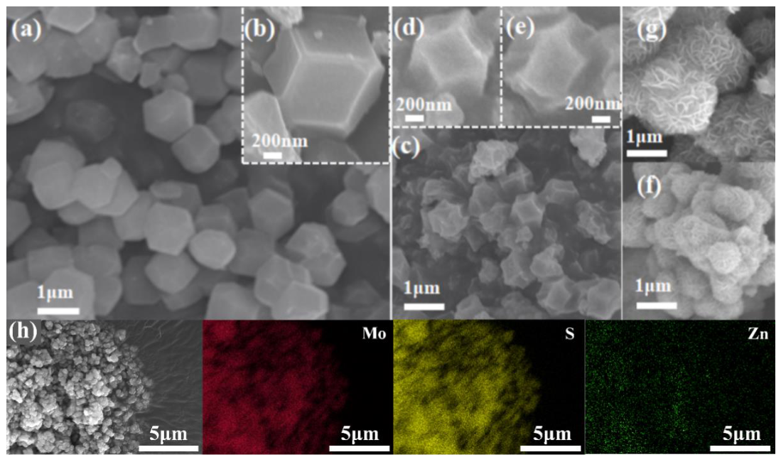
Figure 4.
Cyclic voltammetry (CV) curves of the first three cycles: (a) MoS2, (b) ZnS@NC@MoS2; and the CV curves at different cycle numbers for both materials: (c) the first cycle, (d) the third cycle.
Figure 4.
Cyclic voltammetry (CV) curves of the first three cycles: (a) MoS2, (b) ZnS@NC@MoS2; and the CV curves at different cycle numbers for both materials: (c) the first cycle, (d) the third cycle.
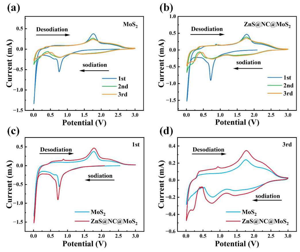
Figure 5.
Galvanostatic charge–discharge curves of the first three cycles at a current density of 100 mA·g-1for (a) MoS2 and (b) ZnS@NC@MoS2; (c) cycling performance at 100 mA·g-1for both electrodes; (d) comparison of actual discharge specific capacities during cycling at 100 mA·g-1; (e) rate capability at various current densities; (f) comparison of rate capability.
Figure 5.
Galvanostatic charge–discharge curves of the first three cycles at a current density of 100 mA·g-1for (a) MoS2 and (b) ZnS@NC@MoS2; (c) cycling performance at 100 mA·g-1for both electrodes; (d) comparison of actual discharge specific capacities during cycling at 100 mA·g-1; (e) rate capability at various current densities; (f) comparison of rate capability.
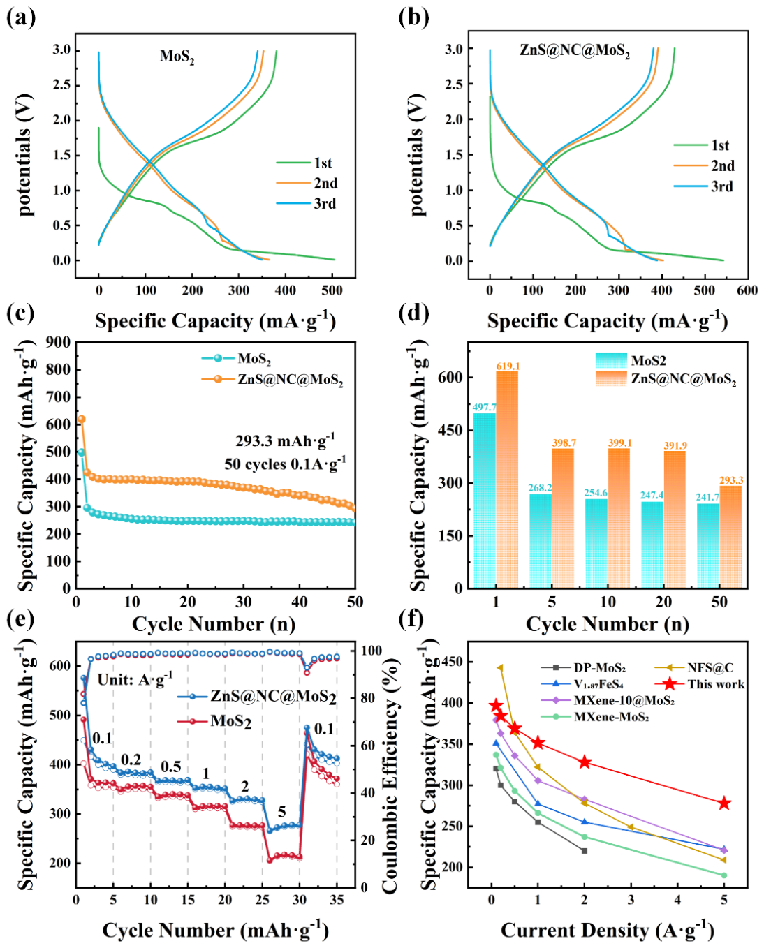
Figure 6.
GITT measurements of ZnS@NC@MoS2: (a) GITT curves, (b) DNa+; GITT measurements of MoS2: (c) GITT curves, (d) DNa+; EIS measurements of MoS2 and ZnS@NC@MoS2 at OCP and after one cycle: (e) Nyquist plots, (f) fitted Rct values.
Figure 6.
GITT measurements of ZnS@NC@MoS2: (a) GITT curves, (b) DNa+; GITT measurements of MoS2: (c) GITT curves, (d) DNa+; EIS measurements of MoS2 and ZnS@NC@MoS2 at OCP and after one cycle: (e) Nyquist plots, (f) fitted Rct values.
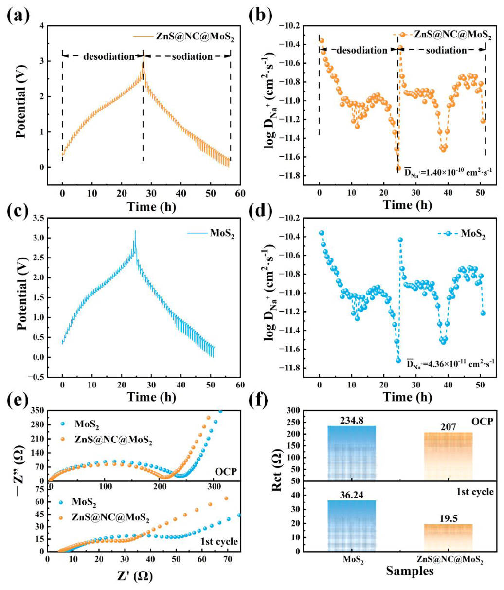
Figure 7.
Presents the CV curves recorded at various scan rates ranging from 0.2 to 8.0 mV·s-1: (a) MoS2, (b) ZnS@NC@MoS2; (c) the corresponding b-values of ZnS@NC@MoS2 derived from the CV curves at different scan rates; (d) comparison of the pseudocapacitive contribution ratios between MoS2 and ZnS@NC@MoS2 at scan rates from 0.2 to 8.0 mV·s-1; and (e) the pseudocapacitive contribution ratios of ZnS@NC@MoS2 at 8.0 mV·s-1 scan rates.
Figure 7.
Presents the CV curves recorded at various scan rates ranging from 0.2 to 8.0 mV·s-1: (a) MoS2, (b) ZnS@NC@MoS2; (c) the corresponding b-values of ZnS@NC@MoS2 derived from the CV curves at different scan rates; (d) comparison of the pseudocapacitive contribution ratios between MoS2 and ZnS@NC@MoS2 at scan rates from 0.2 to 8.0 mV·s-1; and (e) the pseudocapacitive contribution ratios of ZnS@NC@MoS2 at 8.0 mV·s-1 scan rates.
Disclaimer/Publisher’s Note: The statements, opinions and data contained in all publications are solely those of the individual author(s) and contributor(s) and not of MDPI and/or the editor(s). MDPI and/or the editor(s) disclaim responsibility for any injury to people or property resulting from any ideas, methods, instructions or products referred to in the content. |
© 2026 by the authors. Licensee MDPI, Basel, Switzerland. This article is an open access article distributed under the terms and conditions of the Creative Commons Attribution (CC BY) license (http://creativecommons.org/licenses/by/4.0/).
Copyright: This open access article is published under a Creative Commons CC BY 4.0 license, which permit the free download, distribution, and reuse, provided that the author and preprint are cited in any reuse.


